22


ON LOAD TAP CHANGERSRS 6.3 / RS 6
TECHNICAL DATA
Hyundai Heavy IndustriesCo. Bulgaria
2017-2

EA 710.2/17 EN
2
Contents 1. Basic characteristics .......................................................................................................................... 3
1.1. Basic technical data .............................................................................................................. 3 1.2. Rated through current (Iu), rated step voltages (Ui), rated switching capacity (PstN) ......... 4 1.3. Electrical and mechanical endurance ................................................................................... 5 1.4. Insulation level ..................................................................................................................... 5
2. Review of the different RS 6.3 / RS 6 types ........................................................................................7
2.1. Main dimensions ................................................................................................................... 7 2.2. Basic connection diagrams .................................................................................................... 8 2.2.1. Designation and range of regulation ...................................................................... 8 2.2.2. Examples of basic connection diagrams .............................................................. 10
3. Appendix ........................................................................................................................................... 12
3.1. Overall dimension drawings of OLTCs ............................................................................. 12 3.2. Additional drawings of OLTCs .......................................................................................... 12 3.3. RS 6.3 and RS 6 – driving shafts arrangement ...................................................................12
Notes:
1) This technical data catalog is intended to be used by transformer designers as well as oth-er technical personnel responsible for maintenance, diagnostics and operation of OLTCs.
2) HHI-Bulgaria reserves the right to make changes in the overall dimension drawings and connection diagrams without prior notice. Updated drawings are provided as part of the technical documentation received by the customer at the time of the product delivery; updated drawings can be provided also to potential customers on request.
3) TheOLTCismanufacturedaccordingtothespecificdataintheorderspecificationsheetfilledinbytheclient.
4) HHI-Bulgaria is not responsible for the client’s improper selection of an OLTC.

3
1. Basic characteristicsThe OLTCs of Hyundai Heavy Industries Co. Bulgaria (HHIB) meet the requirements of the IEC 60214-1 standard.1.1. Basic technical data
Table 1OLTC type RS6.3 – III – 1250 A
Number of phases and application 3 – in the neutralMaximum rated through current (A) 1250Short circuit withstand current (kA):
R.m.s. value (3 s duration) 15
Peak value 37,5Maximum rated step voltage per phase (V) 2500Rated step capacity (kVA) 3125Rated frequency (Hz) 50...60
Insulation to earth:
Highest voltage for equipment Um (kV, r.m.s.)1) 41,5 72,5 123 170 245(300)Rated separate source AC withstand voltage, 1 min duration (kV, r.m.s.) 95 140 230 325 460
Rated switching impulse withstand voltage (kV,250/2500μs) - - 460 620 850
Rated lightning impulse withstand voltage (kV,1,2/50μs) 250 350 550 750 1050
Number of operating positions Without change-over selector – max of 14With change-over selector – max of 27
Tap selector
Threedifferent tapselectorsizes(K,L,M,)areavailablecorresponding to therequirements of the voltage stress across the regulating winding. The tap selector insulation level can be chosen independently from the maximum operating voltage to earth.For the test voltages, see Section 1.4.
Oil pressure in the diverter switch oil compartment Operating oil pressure up to 0,3x10⁵ Pa (testing pressure – 0,6x10⁵ Pa). Vacuum-proof for drying.
Siphon for oil draining from the diverter switch oil compartment Basic design – left or right
Drying In vacuum furnace – up to 110oCIn kerosene vapour – up to 125oC
Tap selector size
Weight in kg (approx.)
without change-over selector
with change-over selector
Displaced by the OLTC volume in dm3 (approx.)
41,5 kV72,5 kV123 kV170 kV245 kV
Oilfillingquantityof the diverter switch oil compartment – Vs (dm3)
41,5 kV 21572,5 kV 240123 kV 274170 kV 324245 kV 350
Oil temperature range for OLTC operationunder rated load conditions From -25oC to +115oC
1)InaccordancewithIEC60214-1,chapter3.60highesteffectivevalueforphase-to-phasevoltageinathree-phase system for which an on-load tap-changer is designed with respect to its insulation.
Notes:1.RS6OLTCsarewithellipticalupperflange.RS6.3OLTCsarewithroundupperflange.Allthe rest technical data are the same.
2. Minimum conservator volume due to the temperature expanse of the oil at temperature chang-esfrom-30°Cupto+100°Cis:∆V=0,1.Vs+5(dm3).
3. RS 6.3 OLTCs can operate with a rated load temperature from -25°C to +100°C.
K L M
460 470 492480 490 512255 260 265280 285 290314 320 325364 370 375390 395 400

EA 710.2/17 EN
4
1.2. Rated through current (Iu), rated step voltages (Ui), rated switching capacity (PstN)
Table 2 shows the maximum values of Iu, the corresponding step voltage Ui and the rated step capacity PstN.
Table 2: Maximum rated through current (Ium), rated step voltages (Ui), rated step capacity (PstN)OLTC RS 6.3
Ium (A) 1250Ui (V) 2500
PstN (kVA) 3125 The rated through current Iu and its corresponding rated step voltage Ui are determined by the curve of the rated step capacity (Fig. 1).
Fig. 1: Step capacities (rated through current Iu [A]; rated step voltage Ui [V])
In the case of overexcitation of the transformer, the maximum step voltage can be increased with 10 % under the condition that the step capacity is limited to its rated value.
ThespecificcommutationregimesareclarifiedinthetechnicaldatacatalogforallHHIBOLTCs.

5
1.3. Electrical and mechanical enduranceTable 3 gives the average values for the number of switching operations till inspection of the diverter switch and replacement of the contacts. These values have been obtained as a result of experimenting withrealloadsundermaximumratedthroughcurrentIum(A),ratedstepvoltageUi(V),andcosφ=1.
Table 3: Electrical and mechanical enduranceOLTC RS 6.3
Number of switching operations till inspection (oil replacement) 1) 50 000Number of switching operations till contact replacement 150 000Mechanical endurance – number of switching operations 500 000
1) or in operation for maximum 2 years
Detailedinformationaboutthenumberofswitchingoperationstillinspectionforthedifferenttapchangersisgiven in the RS 6.3 / RS 6 Installation and Operation Manual. At currents that are lower than the rated value, the number of switching operations n till replacement of the contacts is determined from the curve in Fig. 2.
Fig. 2: Switching operations till replacement of contacts
1.4. Insulation levelThe insulation level of the OLTC is determined by a number of withstand voltage values.The rated withstand voltage values to earth are given in Table 1. These voltages are determined by national and international standards.Theinternalinsulationisdimensioneddependingonthevoltagesdefinedbythetransformerwindingtapstothedifferentpartsoftheselector,change-overselectorandthediverterswitch.Fig. 3 shows the main connection diagrams and the typical insulation distances to them. ThewithstandvoltagevaluesfromthedifferentinsulationdistancesaregiveninTable4.ForacorrectOLTC selection, these voltage values should correspond to the voltage values that occur during the lightning impulse test, the induced voltage test and the power frequency voltage test of the transformer. The least favorable position of the OLTC should be taken into account. The insulation to earth and the tap selector insulation size are not mutually connected and can be selectedinaccordancewiththespecificrequirements.

EA 710.2/17 EN
6
ON LOAD TAP CHANGERS RS 6.3 – III – 1250A
Fig. 3: Specificinsulationdistancesofthetransformerwindings
Table 4: Withstand voltages
Insulation distances
Rated withstand voltage (kV)SelectorsizeK Selector size L Selector size M
1.2/50 µs
50Hz 1min
1.2/50 µs
50Hz 1min
1.2/50 µs
50Hz 1min 25a0 100 25 100 25 100
b1 200 55 275 80 330 100b2 200 55 280 80 320 100c1 290 65 390 120 450 130c2 290 65 390 120 450 130d 300 80 300 80 320 120
WITHOUT CHANGE-OVER SELECTOR
WITH REVERSE CHANGE-OVER SELECTOR
WITH COARSE CHANGE-OVER SELECTOR

7
2. Review of the RS 6.3 / RS 6 types2.1. Main dimensions 1)
Fig. 4: Main dimensions of RS 6.3 / RS 6
Table 5: RS 6.3 / RS 6
Um(kV)
SELECTOR SIZEK L M
h d h d h d41.5 1832 481 2012 481 2162 48172.5 1933 481 2113 481 2263 481123 - 481 2248 481 2938 481170 - - - - 2541 481245 - - - - 2680 481
1) For the rest of the dimensions, see appendices.
WITHOUT CHANGE-OVER SELECTOR
WITH REVERSE CHANGE-OVER SELECTOR
WITH COARSE CHANGE-OVER SELECTOR

EA 710.2/17 EN
8
2.2. Basic connection diagrams
Fig. 5 and 5a show the basic connection diagrams where the selector contacts are designated according to the overall dimension drawings.
Fig. 5: Basic connection diagrams

9
Fig. 5a: Basic connection diagrams

EA 710.2/17 EN
10
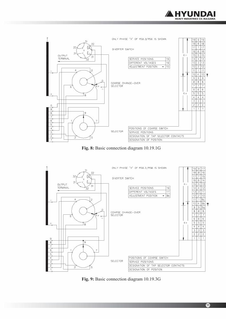
Figures 6, 7, 8 and 9 show the basic connection diagrams; the designation of the operating positions and the respective positions of the selector and change-over selector contacts.
Fig. 6: Basic connection diagram 10.19.1W
Fig. 7: Basic connection diagram 10.19.3W
11
Fig. 8: Basic connection diagram 10.19.1G
Fig. 9: Basic connection diagram 10.19.3G

EA 710.1e/15 ENG
12
3. Appendices
3.1. Overall dimension drawings of OLTCs
RS 6 – III – 1250 №273e
RS 6.3 – III – 1250 №273.3e
OLTCs with pressure relief device and tie-in resistors №485Q
3.2. Additional drawings of OLTCs
RS 6.3/RS 6 – standard OLTC set №555.1
RS 5/RS 5.3 – 630A & 1250 A, RSV 5.3, RS 6/RS 6.3/RSV 6.3 – arrangement of tap selector terminals
№1160
3.3. OLTCs type RS 6.3 and RS 6 – driving shafts arrangement
RS 5/RS 6 – driving shafts arrangement №M6.3.100.001.00e
RS 5.3/RS 6.3 – driving shafts arrangement №M6.3.100.002.01e
Please note: The overall dimension drawings and the basic connection diagrams can be changed without prior notice.

ON LOAD TAP CHANGERSTYPE RS 6 – III – 1250 A
№273e
2017

ON LOAD TAP CHANGERSTYPE RS 6.3 – III – 1250 A
№273.3е
2017

ON LOAD TAP CHANGER WITH A PRESSURE RELIEF DEVICE
AND TIE-IN RESISTORS
№485Q
2017

ON LOAD TAP CHANGERSTANDART SET
№555.1
2017

OLTCs RS 5/RS 5.3 – 630A & 1250 A, RSV 5, RS 6/RS 6.3/RSV 6.3 – ARRANGEMENT OF
TAP SELECTOR TERMINALS
№1160
2017 Sheet 1/2

OLTCs RS 5/RS 5.3 – 630A & 1250 A, RSV 5, RS 6/RS 6.3/RSV 6.3 – ARRANGEMENT OF
TAP SELECTOR TERMINALS
№1160
2017 Sheet 2/2

ON LOAD TAP CHANGER RS 5/RS 6DRIVING SHAFTS ARRANGEMENT
№M 6.3.100.001.00e
2017

ON LOAD TAP CHANGER RS 5.3/RS 6.3/RSV 5.3/RSV 6.3
DRIVING SHAFTS ARRANGEMENT
№M 6.3.100.002.01e
2017


