Z. angew. Math. Phys. DOI 10.1007/s00033-006-5058-y c 2006 Birkh¨auser Verlag, Basel Zeitschrift f¨ ur angewandte Mathematik und Physik ZAMP On the bidirectional vortex and other similarity solutions in spherical coordinates Joseph Majdalani * and Sjoerd W. Rienstra Abstract. The bidirectional vortex refers to the bipolar, coaxial swirling motion that can be triggered, for example, in cyclone separators and some liquid rocket engines with tangential aft-end injectors. In this study, we present an exact solution to describe the corresponding bulk motion in spherical coordinates. To do so, we examine both linear and nonlinear solutions of the momentum and vorticity transport equations in spherical coordinates. The assumption will be that of steady, incompressible, inviscid, rotational, and axisymmetric flow. We further relate the vorticity to some power of the stream function. At the outset, three possible types of similarity solutions are shown to fulfill the momentum equation. While the first type is incapable of satisfying the conditions for the bidirectional vortex, it can be used to accommodate other physical settings such as Hill’s vortex. This case is illustrated in the context of inviscid flow over a sphere. The second leads to a closed-form analytical expression that satisfies the boundary conditions for the bidirectional vortex in a straight cylinder. The third type is more general and provides multiple solutions. The spherical bidirectional vortex is derived using separation of variables and the method of variation of parameters. The three-pronged analysis presented here increases our repertoire of general mean flow solutions that rarely appear in spherical geometry. It is hoped that these special forms will permit extending the current approach to other complex fluid motions that are easier to capture using spherical coordinates. Mathematics Subject Classification (2000). 35D05, 35J05, 35J60, 76B47, 76M23. Keywords. Vortex flow, cyclone, nonlinear PDE, multiple solutions. 1. Introduction In the last five decades, considerable attention has been given to naturally occur- ring swirl patterns in thermal and physical transport applications [1–25]. In that vein, different methods have been employed to simulate and trigger swirl in cylin- drical or conical chambers using, for example, tangential fluid injection, inlet swirl vanes, aerodynamically-shaped swirl blades, propellers, vortex trippers, twisted tape inserts, coiled wires, vortex generators, and other swirl-prop devices. Recently, an efficient cooling method has been proposed by Chiaverini and co- * Corresponding author: Joseph Majdalani, e-mail: [email protected]
Zeitschrift fur angewandteMathematik und Physik ZAMP
On the bidirectional vortex and other similarity solutions inspherical coordinates
Joseph Majdalani∗ and Sjoerd W. Rienstra
Abstract. The bidirectional vortex refers to the bipolar, coaxial swirling motion that canbe triggered, for example, in cyclone separators and some liquid rocket engines with tangentialaft-end injectors. In this study, we present an exact solution to describe the correspondingbulk motion in spherical coordinates. To do so, we examine both linear and nonlinear solutionsof the momentum and vorticity transport equations in spherical coordinates. The assumptionwill be that of steady, incompressible, inviscid, rotational, and axisymmetric flow. We furtherrelate the vorticity to some power of the stream function. At the outset, three possible types ofsimilarity solutions are shown to fulfill the momentum equation. While the first type is incapableof satisfying the conditions for the bidirectional vortex, it can be used to accommodate otherphysical settings such as Hill’s vortex. This case is illustrated in the context of inviscid flow overa sphere. The second leads to a closed-form analytical expression that satisfies the boundaryconditions for the bidirectional vortex in a straight cylinder. The third type is more generaland provides multiple solutions. The spherical bidirectional vortex is derived using separation ofvariables and the method of variation of parameters. The three-pronged analysis presented hereincreases our repertoire of general mean flow solutions that rarely appear in spherical geometry.It is hoped that these special forms will permit extending the current approach to other complexfluid motions that are easier to capture using spherical coordinates.
In the last five decades, considerable attention has been given to naturally occur-ring swirl patterns in thermal and physical transport applications [1–25]. In thatvein, different methods have been employed to simulate and trigger swirl in cylin-drical or conical chambers using, for example, tangential fluid injection, inlet swirlvanes, aerodynamically-shaped swirl blades, propellers, vortex trippers, twistedtape inserts, coiled wires, vortex generators, and other swirl-prop devices.
Recently, an efficient cooling method has been proposed by Chiaverini and co-
Figure 1. Schematic of the Cool Wall Bidirectional Vortex Combustion Chamber (CWBVCC).
workers [26–28] who have managed to reproduce cyclonic motion inside a liquidrocket engine (see Fig. 1). Their technique is based on inducing a coaxial, co-spinning, bidirectional flow comprising two distinct concentric fields: an outer an-nular vortex and an inner, tubular vortex. The flow configuration in this chamberis unique in that the oxidizer is injected tangentially into the combustion chamberand just upstream of the nozzle; the process results in a swirling combustion fieldthat exhibits an outer, virtually nonreactive, flow region. This so-called outervortex fills the annular region separating the combustion core from the chamber’scircumferential wall. The combustion core is formed from the oxidizer mixing andreacting with the fuel. The latter is injected radially or axially at the chamberhead end. Before reaching the fuel injector’s faceplate, the outer vortex (composedof cool oxidizer) coils around and up the chamber wall. The engendered thermalblanket protects the chamber wall from fluctuating heating loads. The attendantlowering of wall temperatures is sufficiently efficient to the extent that a laboratorytest using a fuel-rich Hydrogen-Oxygen combustion could be safely sustained in aPlexiglas model of this engine [26–28]. The thermal protection feature not onlyreduces cooling requirements but leads to appreciable cost reduction, prolongedlife, more flexibility in material selection, and reduced weight. The inner vortex,on the other hand, plays an important role in improving combustion efficiency.The inherent swirl increases fuel residence time, mixing, and turbulence, thus im-proving overall efficiency and ballistic performance. The spinning vortices providean extended flow path that exceeds the geometric length of the chamber, thustaking full advantage of the chamber’s volumetric capacity.
The utilization of bidirectional vortex motion is, in fact, a well established tech-nology that dates back to the 1950s. The earliest investigations may be credited
On the bidirectional vortex 3
Figure 2. Schematic of a conical separator depicting its key components.
to the experimental work of ter Linden [1] on dust separators and the treatmentof hydraulic and gas cyclones by Kelsall [2] and Smith [3, 4]. Theoretical analyseshave also been carried out by Fontein and Dijksman [5], Smith [3, 4], and Bloorand Ingham [6–8]. Semi-empirical models are, in turn, available from Reydon andGauvin [9], Vatistas, Lin and Kwok [10, 11], Vatistas [12], and others. In view ofcontinual progress in computational mechanics, numerical simulations have beenrecently undertaken by Hsieh and Rajamani [13], Hoekstra, Derksen and Van denAkker [14], Derksen and Van den Akker [15], and Fang, Majdalani and Chiaverini[16].
Generally, cyclone technology is implemented in coal gas purificators, spraydryers, oil-water separators, gas scrubbers, gas dedustors, hydrocyclones, andmagneto-hydrodynamic gas core nuclear rockets. Some are widely used in thepetrochemical and powder processing industries where they are employed in cata-lyst or product recovery, scrubbing, and dedusting. The typical cyclone separatorconsists of an upper cylindrical can with a central outlet tube and a lower conicalsection with bottom opening (see Fig. 2). An involute inlet section permits thetangential injection of liquid or gaseous mixtures. The spinning centrifugal motioncauses denser and coarser particles to gather along the conical walls. Heavier par-ticles precipitate toward the base of the cyclone (the spigot) where the underflowis withdrawn.
The main difference between a purely cyclonic flow and that reproduced insidethe NASA sponsored Cool Wall Bidirectional Vortex Combustion Chamber (CW-BVCC) is that the latter exhibits only one outlet section (Fig. 1 versus 2). This
4 J. Majdalani and S. W. Rienstra ZAMP
difference is minor because the presence of a secondary outlet does not alter thebulk flow motion. The spigot serves as a collection cavity through which heavyparticles may be trickled and filtered out of the mixture. The spigot does notaffect the main characteristics of the swirling stream inside the cyclone, especiallyunder high speed conditions for which friction may be discounted.
The purpose of this study is twofold. First, it is to explore both linear andnonlinear solutions of the vorticity transport equation in spherical coordinates un-der steady, inviscid, incompressible, rotational, and axisymmetric flow conditions.Second, it is to explore possible forms of the solution for the bidirectional vortexthat can be used to describe cyclonic motion. In the process, the inviscid vortic-ity transport equation will be shown to exhibit multiple solutions of which threetypes will be singled out. These will be considered one-by-one and solved wheneverpossible.
2. Mathematical model
In seeking an incompressible solution for steady, inviscid, rotational flowfields, itis customary to use the vorticity-stream function approach [29]. Accordingly, onesolves ∇× (u×ω) = 0 and ω = ∇×u. While solutions in Cartesian or cylindricalcoordinates are quite common, those in spherical geometry remain a rarity [29, 30].In the present work, the bidirectional vortex will be formulated using the spatialcoordinates (R,φ, θ) shown in Fig. 3. Note that in relation to a Cartesian referenceframe, ours are defined by x = R sinφ cos θ, y = R sinφ sin θ and z = R cos φ.
2.1. Governing equations
In an axisymmetric field in which changes in the θ-directions are null, the equationfor continuity reduces to
∂
∂R(uRR2 sinφ) +
∂
∂φ(uφR sin φ) = 0 (2.1)
where uR and uφ are the two components of the velocity vector u. A Stokes streamfunction ψ(R,φ) that satisfies Eq. (2.1) can be defined as
∂ψ
∂φ= uRR2 sinφ,
∂ψ
∂R= −uφR sin φ (2.2)
Next, Euler’s momentum equation can be reduced to the vorticity transport equa-tion following the usual steps. One gets
∇× (u× ω) = 0 (2.3)
Equation (2.3) is the steady vorticity transport equation that fulfills the con-servation of momentum principle.
On the bidirectional vortex 5
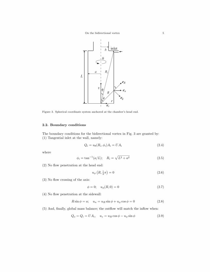
Figure 3. Spherical coordinate system anchored at the chamber’s head end.
2.2. Boundary conditions
The boundary conditions for the bidirectional vortex in Fig. 3 are granted by:(1) Tangential inlet at the wall, namely:
Qi = uθ(Ri, φi)Ai = UAi (2.4)
where
φi = tan−1(a/L); Ri =√
L2 + a2 (2.5)
(2) No flow penetration at the head end:
uφ
(R, 1
2π)
= 0 (2.6)
(3) No flow crossing of the axis:
φ = 0; uφ(R, 0) = 0 (2.7)
(4) No flow penetration at the sidewall:
R sinφ = a; un = uR sin φ + uφ cos φ = 0 (2.8)
(5) And, finally, global mass balance; the outflow will match the inflow when:
Qo = Qi = UAi, uz = uR cos φ− uφ sinφ (2.9)
6 J. Majdalani and S. W. Rienstra ZAMP
2.3. Swirl component
In order to capture the behavior of the spin velocity uθ, it is useful to consider theθ-momentum equation. By virtue of the attendant assumptions, one is left with(
uR∂
∂R+
uφ
R
∂
∂φ
)(uθR sin φ) = 0 (2.10)
Since (u ·∇)(uθR sin φ) = 0, uθR sinφ = h(ψ) must be constant along any stream-line. In order to further satisfy Eq (2.4), a free vortex form must be exhibited bythe swirling velocity. By restricting our solutions to a constant h, we arrive at
uθ = URi sin φi/(R sin φ) (2.11)
The singularity on R sin φ = 0 is a characteristic of inviscid swirling flows [8]. Thephysics of the problem suggest a boundary layer structure near the chamber axisin the form of a forced core vortex; the latter is known to form due to viscousstresses along the axis of rotation.
2.4 Vorticity-stream function approach
Because uθ does not appear in the continuity equation, one may invoke the vorticity-stream function approach and replace the remaining components of velocity using
uR =1
R2 sin φ
∂ψ
∂φ, uφ = − 1
R sin φ
∂ψ
∂R(2.12)
The corresponding vorticity becomes
ωθ =1R
[∂
∂R(Ruφ)− ∂uR
∂φ
]; ωR = ωφ = 0 (2.13)
Having realized that the inviscid vorticity gives a single component in the swirldirection, ω = ωθ, one may drop the subscript θ and write
ω =1R
∂
∂R(Ruφ)− 1
R
∂uR
∂φ(2.14)
Substitution into the vorticty transport equation requires evaluating
∂
∂R
(ω
R sin φ
∂ψ
∂φ
)− ∂
∂φ
(ω
R sinφ
∂ψ
∂R
)= 0 (2.15)
This will be true whenω
R sin φ= f(ψ) (2.16)
A solution of the form f(ψ) = Cψλ will be sought here although other solutionsmay exist for which f is not a power of ψ. Three cases can be singled out depending
On the bidirectional vortex 7
Figure 4. The case of uniform flow past a sphere leading to an inviscid, irrotational solution.
on the exponent λ. Specifically, three types of solutions may be defined viz.
λ =
0; type I1; type IIother; type III
(2.17)
3. Possible solutions
The suitability of Eq. (2.17) to describe the bidirectional vortex motion must betested. We begin by considering the simplest form, namely, the λ = 0 case.
3.1 Type I solution: potential flow past a sphere
For λ = 0, one obtains f(ψ) = C; the vorticity becomes proportional to R sinφ.Equation (2.16) yields ω = CR sin φ, which can be readily substituted into Eq. (2.14).The result can be simplified using Eq. (2.2) and put in the form
∂2ψ
∂R2+
sinφ
R2
∂
∂φ
(1
sin φ
∂ψ
∂φ
)+ CR2 sin2 φ = 0 (3.1)
Assuming a separable solution of the form ψ = F (R) sin2 φ, it can be shown that
R2F ′′(R)− 2F (R) = −CR4 or F (R) = C1R2 +
C2
R− C
10R4 (3.2)
A type I stream function corresponding to this case is hence unraveled, specifically,
ψ =(
C1R2 +
C2
R− C
10R4
)sin2 φ (3.3)
Unfortunately, this form cannot accommodate the boundary conditions attributedto the bidirectional vortex, given by Eqs. (2.6)–(2.9). Instead, Eq. (3.3) can be
8 J. Majdalani and S. W. Rienstra ZAMP
readily adapted to describe the flow conditions associated with a uniform flowpast a sphere (c.f. the outer part of Hill’s spherical vortex [31]). As illustrated inFig. 4, this problem exhibits rather simple boundary conditions. In the far field,one has R → ∞, ψ → 1
2UR2 sin2 φ + const., so that C = 0 and C1 = 12U . The
immediate implication is that of an irrotational flow since ω = CR sinφ = 0. Thecorresponding stream function reduces to
ψ =(
12UR2 +
C2
R
)sin2 φ (3.4)
The remaining constant can be obtained from the hard wall boundary conditionalong the sphere’s radius. Given that ψ(a, φ) = 0, one must have C2 = − 1
2Ua3.This leaves us with the familiar solution
ψ =12UR2 sin2 φ
(1− a3
R3
)with
{uR = 2U cos φ(1− a3R−3)uφ = − 1
2U sinφ(2 + a3R−3)(3.5)
This particular result replicates the outer potential flow profile past a sphere;despite being unsuitable for the bidirectional vortex, it is reproduced here in theinterest of clarity.
3.2 Type II solution: bidirectional vortex
For λ = 1, one recovers the classic linear form, f(ψ) = C2ψ. The correspondingvorticity-stream function relation becomes ω = C2ψR sin φ. Rearward substitu-tion into Eq. (2.14) gives
∂2ψ
∂R2+
1R2
∂2ψ
∂φ2− 1
R2
cos φ
sin φ
∂ψ
∂φ+ C2ψR2 sin2 φ = 0. (3.6)
This is the key equation that needs to be solved for type II behavior.
3.2.1 Separating the vorticity equation
To make progress, we look for similarity solutions of the form ψ(R,φ) = ψ(ζ) withthe similarity variable ζ = 1
2C(x2 + y2) = 12CR2 sin2 φ; this requires evaluating
∂ζ
∂R= CR sin2 φ;
∂ζ
∂φ= CR2 sin φ cos φ (3.7)
Inserting into Eq. (3.6) yields
C sin2 φψ′ + 2Cζ sin2 φψ′′ − C sin2 φψ′ + 2Cζ cos2 φψ′′ + 2Cζψ = 0 (3.8)
and so2Cζ(sin2 φ + cos2 φ)ψ′′ + 2ζCψ = 0 (3.9)
leading to ψ′′ + ψ = 0. The standard solution is, of course,
ψ = C1 sin(
12CR2 sin2 φ
)+ C2 cos
(12CR2 sin2 φ
)(3.10)
On the bidirectional vortex 9
Equation (3.10) is deceptively simple and can be shown to be unsuitable for thebidirectional vortex. The constants of integration must be permitted to vary inorder to capture more complex features of the flow. This will be carried out next.
3.2.2 A more general type II solution
A more general solution for Eq. (3.6) can be pursued in the spirit of Eq. (3.10);for this purpose, one can let
ψ = C1(R,φ) sin(
12R2 sin2 φ
)+ C2(R,φ) cos
(12CR2 sin2 φ
)(3.11)
This Ansatz may be substituted back into Eq. (3.6); after some algebra, one de-duces{
C cos ζ
[sin(2φ)
∂
∂φ+ 2R sin2 φ
∂
∂R
]+ sin ζ
(∂2
∂R2+
1R2
∂2
∂φ2− cot φ
R2
∂
∂φ
)}C1
−{
C sin ζ
[sin(2φ)
∂
∂φ+ 2R sin2 φ
∂
∂R
]− cos ζ
(∂2
∂R2+
1R2
∂2
∂φ2− cot φ
R2
∂
∂φ
)}C2
= 0 (3.12)
In the interest of clarity, Eq. (3.12) can be written as
The complicating dependence of (3.13) on ζ = 12CR2 sin2 φ can be averted by
restricting our attention to solutions that satisfy
cos(ζ)(CL1C1 + L2C2)− sin(ζ)(L2C1 − CL1C2) = 0 or
{CL1C1 + L2C2 = 0L2C1 − CL1C2 = 0
(3.15)This coupled set has solutions when
(C2L1L1 + L2L2)C1 = (C2L1L1 + L2L2)C2 = 0 (3.16)
Equation (3.16) would, in general, yield interesting solutions of the type assumedin (3.11). However, the resulting fourth-order partial differential equation is ratherinvolved. To make headway, we look for the simpler forms that may be obtainedby setting L1C1 = L2C1 = 0 and L1C2 = L2C2 = 0. These translate into
cos φ sinφ∂C1
∂φ+ R sin2 φ
∂2C1
∂R= 0;
∂2C1
∂R2+
1R2
∂2C1
∂φ2− cot φ
R2
∂C1
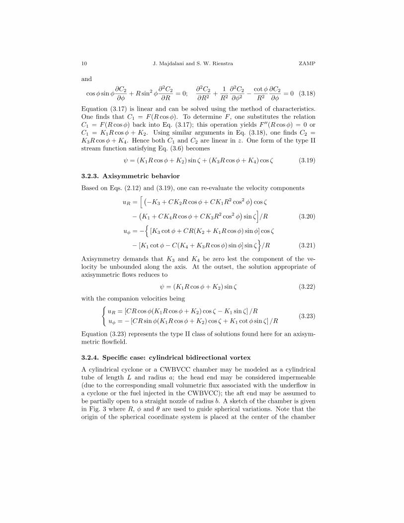
∂φ= 0 (3.17)
10 J. Majdalani and S. W. Rienstra ZAMP
and
cos φ sinφ∂C2
∂φ+ R sin2 φ
∂2C2
∂R= 0;
∂2C2
∂R2+
1R2
∂2C2
∂φ2− cot φ
R2
∂C2
∂φ= 0 (3.18)
Equation (3.17) is linear and can be solved using the method of characteristics.One finds that C1 = F (R cos φ). To determine F , one substitutes the relationC1 = F (R cos φ) back into Eq. (3.17); this operation yields F ′′(R cos φ) = 0 orC1 = K1R cos φ + K2. Using similar arguments in Eq. (3.18), one finds C2 =K3R cos φ + K4. Hence both C1 and C2 are linear in z. One form of the type IIstream function satisfying Eq. (3.6) becomes
ψ = (K1R cos φ + K2) sin ζ + (K3R cos φ + K4) cos ζ (3.19)
3.2.3. Axisymmetric behavior
Based on Eqs. (2.12) and (3.19), one can re-evaluate the velocity components
uR =[ (−K3 + CK2R cos φ + CK1R
2 cos2 φ)cos ζ
− (K1 + CK4R cos φ + CK3R
2 cos2 φ)sin ζ
]/R (3.20)
uφ = −{
[K3 cot φ + CR(K2 + K1R cos φ) sin φ] cos ζ
− [K1 cot φ− C(K4 + K3R cos φ) sin φ] sin ζ}
/R (3.21)
Axisymmetry demands that K3 and K4 be zero lest the component of the ve-locity be unbounded along the axis. At the outset, the solution appropriate ofaxisymmetric flows reduces to
ψ = (K1R cos φ + K2) sin ζ (3.22)
with the companion velocities being{uR = [CR cos φ(K1R cos φ + K2) cos ζ −K1 sin ζ] /R
uφ = − [CR sinφ(K1R cos φ + K2) cos ζ + K1 cot φ sin ζ] /R(3.23)
Equation (3.23) represents the type II class of solutions found here for an axisym-metric flowfield.
3.2.4. Specific case: cylindrical bidirectional vortex
A cylindrical cyclone or a CWBVCC chamber may be modeled as a cylindricaltube of length L and radius a; the head end may be considered impermeable(due to the corresponding small volumetric flux associated with the underflow ina cyclone or the fuel injected in the CWBVCC); the aft end may be assumed tobe partially open to a straight nozzle of radius b. A sketch of the chamber is givenin Fig. 3 where R, φ and θ are used to guide spherical variations. Note that theorigin of the spherical coordinate system is placed at the center of the chamber
On the bidirectional vortex 11
head end; alternatively, r and z are used to represent the cylindrical radial andaxial coordinates in a coincident reference frame. The fraction of the radius thatis open to flow may be defined by β = b/a and the chamber’s aspect ratio byl = L/a.
Excluding axisymmetry (which is already satisfied) the remaining physical con-ditions described in Eqs. (2.6)–(2.9) may now be applied to Eq. (3.23). Firstly,the state of no flow across the head end requires that uφ
(R, 1
2π)
= 0; hence
uφ = −CC1K2 cos(
12CR2
)= 0 (3.24)
This is true when K2 = 0 or ψ = K1R cos φ sin ζ. One is left with{uR = K1(CR2 cos2 φ cos ζ − sin ζ)/R
uφ = −K1(CR2 cos φ sin φ cos ζ + cot φ sin ζ)/R(3.25)
Secondly, one can enforce the no flow across the sidewall where the radiusa remains invariant. Accordingly, the component of the velocity normal to thesurface must vanish along R sin φ = a. Based on geometric considerations, thecomponent of velocity un normal to the sidewall may be evaluated from
un = uR sin φ + uφ cos φ, R = a csc φ (3.26)
whereuR = K1 sin φ
[Ca cot2 φ cos
(12Ca2
)− sin(
12Ca2
)/a
](3.27)
anduφ = −K1 sin φ
[Ca cot φ cos
(12Ca2
)+ cot φ sin
(12Ca2
)/a
](3.28)
Equation (3.26) becomes
un = −(K1/a) sin(
12Ca2
)(3.29)
The no flow across the sidewall requires that un = 0 or sin(
· [2πa−2R2 cos φ sin φ cos(πa−2R2 sin2 φ) + cotφ sin(πa−2R2 sin2 φ)]
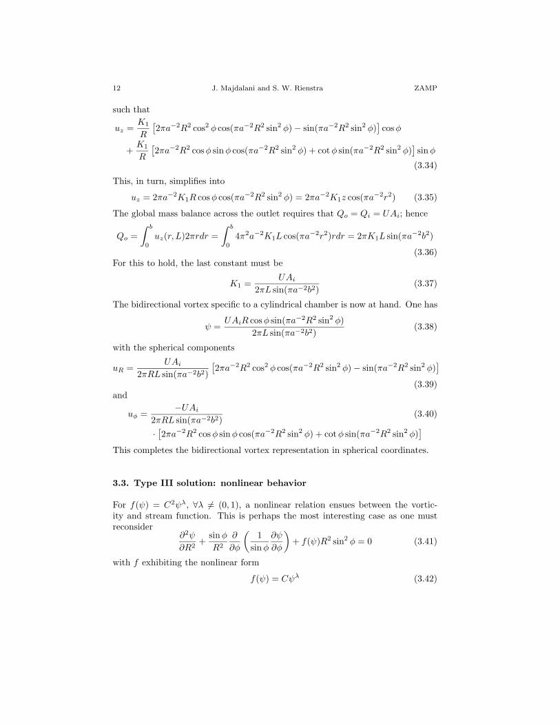
This completes the bidirectional vortex representation in spherical coordinates.
3.3. Type III solution: nonlinear behavior
For f(ψ) = C2ψλ, ∀λ 6= (0, 1), a nonlinear relation ensues between the vortic-ity and stream function. This is perhaps the most interesting case as one mustreconsider
∂2ψ
∂R2+
sin φ
R2
∂
∂φ
(1
sin φ
∂ψ
∂φ
)+ f(ψ)R2 sin2 φ = 0 (3.41)
with f exhibiting the nonlinear form
f(ψ) = Cψλ (3.42)
On the bidirectional vortex 13
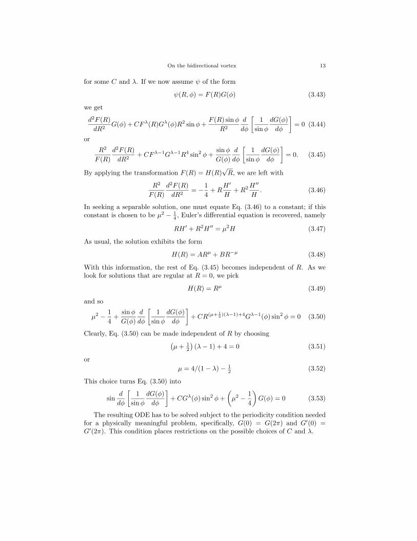
for some C and λ. If we now assume ψ of the form
ψ(R,φ) = F (R)G(φ) (3.43)
we get
d2F (R)dR2
G(φ) + CFλ(R)Gλ(φ)R2 sinφ +F (R) sinφ
R2
d
dφ
[1
sinφ
dG(φ)dφ
]= 0 (3.44)
or
R2
F (R)d2F (R)
dR2+ CFλ−1Gλ−1R4 sin2 φ +
sin φ
G(φ)d
dφ
[1
sinφ
dG(φ)dφ
]= 0. (3.45)
By applying the transformation F (R) = H(R)√
R, we are left with
R2
F (R)d2F (R)
dR2= −1
4+ R
H ′
H+ R2 H ′′
H. (3.46)
In seeking a separable solution, one must equate Eq. (3.46) to a constant; if thisconstant is chosen to be µ2 − 1
4 , Euler’s differential equation is recovered, namely
RH ′ + R2H ′′ = µ2H (3.47)
As usual, the solution exhibits the form
H(R) = ARµ + BR−µ (3.48)
With this information, the rest of Eq. (3.45) becomes independent of R. As welook for solutions that are regular at R = 0, we pick
H(R) = Rµ (3.49)
and so
µ2 − 14
+sin φ
G(φ)d
dφ
[1
sin φ
dG(φ)dφ
]+ CR(µ+ 1
2 )(λ−1)+4Gλ−1(φ) sin2 φ = 0 (3.50)
Clearly, Eq. (3.50) can be made independent of R by choosing(µ + 1
2
)(λ− 1) + 4 = 0 (3.51)
orµ = 4/(1− λ)− 1
2 (3.52)
This choice turns Eq. (3.50) into
sind
dφ
[1
sinφ
dG(φ)dφ
]+ CGλ(φ) sin2 φ +
(µ2 − 1
4
)G(φ) = 0 (3.53)
The resulting ODE has to be solved subject to the periodicity condition neededfor a physically meaningful problem, specifically, G(0) = G(2π) and G′(0) =G′(2π). This condition places restrictions on the possible choices of C and λ.
14 J. Majdalani and S. W. Rienstra ZAMP
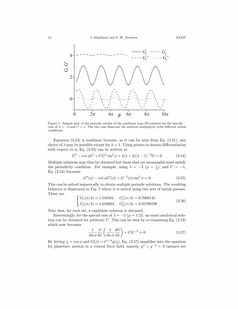
Figure 5. Sample plot of the periodic results of the nonlinear type III solution for the specificcase of λ = −3 and C = 1. The two case illustrate the solution multiplicity with different initialconditions.
Equation (3.53) is nonlinear because, as it can be seen from Eq. (3.51), anychoice of λ may be possible except for λ = 1. Using primes to denote differentiationwith respect to φ, Eq. (3.53) can be written as
Multiple solutions may thus be obtained but those that are meaningful must satisfythe periodicity condition. For example, using λ = −3 (µ = 1
2 ), and C = −1,Eq. (3.54) becomes
G′′(φ)− cot φG′(φ) + G−3(φ) sin2 φ = 0 (3.55)
This can be solved numerically to obtain multiple periodic solutions. The resultingbehavior is illustrated in Fig. 5 where it is solved using two sets of initial guesses.These are {
G1(π/4) = 1.558501, G′1(π/4) = 0.7000145
G2(π/4) = 4.016863, G′2(π/4) = 0.05790198
(3.56)
Note that, for each set, a candidate solution is obtained.Interestingly, for the special case of λ = −3 (µ = 1/2), an exact analytical solu-
tion can be obtained for arbitrary C. This can be seen by re-examining Eq. (3.53)which now becomes
1sinφ
d
dφ
(1
sin φ
dG
dφ
)+ CG−3 = 0 (3.57)
By letting χ = cos φ and G(φ) = C1/4g(χ), Eq. (3.57) simplifies into the equationfor planetary motion in a central force field, namely, g′′ + g−3 = 0 (primes are
On the bidirectional vortex 15
associated with χ). This simple result can be multiplied by g′ and integrated toproduce
12 (g′)2 − 1
2g−2 = constant = 12K1 (3.58)
or g′ = ±√
K1 + g−2. A second integration attempt furnishes
±∫ g K1ξ√
1 + K1ξ2dξ = ±
√1 + K1g2 = K1χ + K2. (3.59)
Hence, 1 + K1g2 = (K1χ + K2)2, or g(χ) = ±√
[(K1χ + K2)2 − 1]/K1. Finally, atype III solution emerges from
G(φ) = ±C1/4
[(K1 cos φ + K2)2 − 1
K1
]1/2
(3.60)
and so, in combination with Eqs. (3.49) and (3.43), one collects
ψ(R,φ) = ±C1/4R
[(K1 cos φ + K2)2 − 1
K1
]1/2
(3.61)
with
uR = ∓ C14 K
1/21 (K1 cos φ + K2)
R [(K1 cos φ + K2)2 − 1]12
uφ = ∓C14
[(K1 cos φ + K2)2 − 1
] 12
K1/21 R sin φ
(3.62)
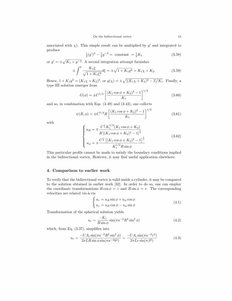
This particular profile cannot be made to satisfy the boundary conditions impliedin the bidirectional vortex. However, it may find useful application elsewhere.
4. Comparison to earlier work
To verify that the bidirectional vortex is valid inside a cylinder, it may be comparedto the solution obtained in earlier work [32]. In order to do so, one can employthe coordinate transformations R cos φ = z and R sin φ = r. The correspondingvelocities are related vis-a-vis{
ur = uR sin φ + uφ cos φ
uz = uR cos φ− uφ sinφ(4.1)
Transformation of the spherical solution yields
ur =−K1
R sin φsin(πa−2R2 sin2 φ) (4.2)
which, from Eq. (3.37), simplifies into
ur =−UAi sin(πa−2R2 sin2 φ)2πLR sin φ sin(πa−2b2)
=−UAi sin(πa−2r2)
2πLr sin(πβ2)(4.3)
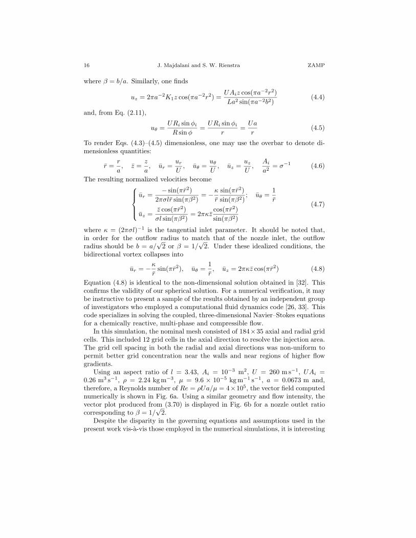
16 J. Majdalani and S. W. Rienstra ZAMP
where β = b/a. Similarly, one finds
uz = 2πa−2K1z cos(πa−2r2) =UAiz cos(πa−2r2)La2 sin(πa−2b2)
(4.4)
and, from Eq. (2.11),
uθ =URi sin φi
R sin φ=
URi sinφi
r=
Ua
r(4.5)
To render Eqs. (4.3)–(4.5) dimensionless, one may use the overbar to denote di-mensionless quantities:
r =r
a, z =
z
a, ur =
ur
U, uθ =
uθ
U, uz =
uz
U,
Ai
a2= σ−1 (4.6)
The resulting normalized velocities become
ur =− sin(πr2)
2πσlr sin(πβ2)= −κ
r
sin(πr2)sin(πβ2)
; uθ =1r
uz =z cos(πr2)σl sin(πβ2)
= 2πκzcos(πr2)sin(πβ2)
(4.7)
where κ = (2πσl)−1 is the tangential inlet parameter. It should be noted that,in order for the outflow radius to match that of the nozzle inlet, the outflowradius should be b = a/
√2 or β = 1/
√2. Under these idealized conditions, the
bidirectional vortex collapses into
ur = −κ
rsin(πr2), uθ =
1r, uz = 2πκz cos(πr2) (4.8)
Equation (4.8) is identical to the non-dimensional solution obtained in [32]. Thisconfirms the validity of our spherical solution. For a numerical verification, it maybe instructive to present a sample of the results obtained by an independent groupof investigators who employed a computational fluid dynamics code [26, 33]. Thiscode specializes in solving the coupled, three-dimensional Navier–Stokes equationsfor a chemically reactive, multi-phase and compressible flow.
In this simulation, the nominal mesh consisted of 184×35 axial and radial gridcells. This included 12 grid cells in the axial direction to resolve the injection area.The grid cell spacing in both the radial and axial directions was non-uniform topermit better grid concentration near the walls and near regions of higher flowgradients.
Using an aspect ratio of l = 3.43, Ai = 10−3 m2, U = 260 m s−1, UAi =0.26 m3 s−1, ρ = 2.24 kg m−3, µ = 9.6 × 10⁻⁵ kg m−1 s−1, a = 0.0673 m and,therefore, a Reynolds number of Re = ρUa/µ = 4×10⁵, the vector field computednumerically is shown in Fig. 6a. Using a similar geometry and flow intensity, thevector plot produced from (3.70) is displayed in Fig. 6b for a nozzle outlet ratiocorresponding to β = 1/
√2.
Despite the disparity in the governing equations and assumptions used in thepresent work vis-a-vis those employed in the numerical simulations, it is interesting
On the bidirectional vortex 17
Figure 6. Vector plots comparing some numerical simulations of the bidirectional vortex withthose obtained analytically.
to note the favorable agreement between theory and computation. In both cases,the flow enters at the base, travels upwardly, and then turns sharply near the headend; after reversing direction at the chamber head end, the flow returns to thebase area where it exits through the open nozzle section. Based on the numericalsolution, the thin boundary layer near the chamber wall appears too small to bediscerned graphically. The small size of this layer supports the idea of an inviscidfluid; this idealization seems to hold well near the wall.
Along the corners of the head end and base sections, the gradual flow curvaturethat is captured by the Navier–Stokes solver is due to viscous effects that eludethe present analytical model. Nonetheless, both analytical and numerical solutionsconfirm the existence of cross flow between the outer and inner vortex regions alongthe length of the chamber. They also confirm the presence of the so-called mantleseparating the outer and inner vortex tubes.
In addition to this independent investigation, it may be worth mentioningthat three-dimensional numerical simulations were carried out by Fang, Majdalaniand Chiaverini under both cold [16] and reactive flow conditions [34]. Therein,favorable comparisons with (4.8) were made, with better agreement being reportedin the cold flow investigation.
5. Concluding remarks
In this paper we have examined several solutions in the context of steady, ax-isymmetric, incompressible, and inviscid vortex motion in spherical coordinates.In addition to the quest for generalizations of the nonlinear vorticity transport
18 J. Majdalani and S. W. Rienstra ZAMP
equation, particular attention has been given to the specific solution that will sat-isfy the physical conditions associated with a single pass, bidirectional vortex. Byidentifying different classes of solutions, the work furnishes procedural steps thatmay be applied to other geometric shapes, with the conical cyclone being one suchexample.
To verify the analysis, the type I solution is shown to reproduce the outerpotential flow past a sphere, one of the few spherical solutions available in theliterature. However, it is the type II solution that is able to accommodate thebidirectional vortex in a straight cylinder. As the latter is obtained in inviscidform, it unravels the free vortex motion that is known to affect the bulk flow awayfrom the core [8]. Near the chamber axis, viscous stresses appreciate as transitionto a forced vortex progresses [35]. The treatment of attendant structures is hopedto be accomplished in later work. So will be the discussion of other solutions withsingle or multiple flow passes. In the interim, incorporation of viscous terms willbe needed in the forced vortex analysis to capture the core motion and to resolvethe boundary layers adjacent to the endwall and sidewall. Finally, the new typeIII class of solutions, engendered from the nonlinear vorticity transport equation,is found to exhibit both numerical and exact outcomes. It is hoped that theiranalysis will promote additional research in those physical settings that are moremanageable in spherical geometry.
Acknowledgments
This project was sponsored by Grant No. CMS-0353518 of the National ScienceFoundation. The first author acknowledges valuable discussions with Dr. Mar-tin J. Chiaverini, Lead Propulsion Engineer of Orbital Technologies Corporation(ORBITEC), Madison, Wisconsin. His support for this project is most gratefullyappreciated.
References
[1] A. J. ter Linden, Investigations into cyclone dust collectors, Proc. Inst. Mech. Engrs 160(1949), 233–251.
[2] D. F. Kelsall, A study of motion of solid particles in a hydraulic cyclone, Trans. Inst. Chem.Engrs 30 (1952), 87–103.
[3] J. L. Smith, An experimental study of the vortex in the cyclone separator, ASME J. BasicEngng -Trans. ASME (1962), 602–608.
[4] J. L. Smith, An analysis of the vortex flow in the cyclone separator, ASME J. Basic Engng-Trans. ASME (1962), 609–618.
[5] F. J. Fontein and C. Dijksman, Recent Developments in Mineral Dressing, Institution ofMining and Metallurgy, London 1953.
[6] M. I. G. Bloor and D. B. Ingham, Theoretical investigation of the flow in a conical hydro-cyclone, Trans. Inst. Chem. Engrs 51 (1973), 36–41.
On the bidirectional vortex 19
[7] M. I. G. Bloor and D. B. Ingham, On the use of Pohlhausen method in three dimensionalboundary layers, J. Appl. Math. Phys. (ZAMP) 28 (1977), 289–299.
[8] M. I. G. Bloor and D. B. Ingham, The flow in industrial cyclones, J. Fluid Mech. 178 (1987),507–519.
[9] R. F. Reydon and W. H. Gauvin, Theoretical and experimental studies of confined vortexflow, Canad. J. Chem. Engng 59 (1981), 14–23.
[10] G. H. Vatistas, S. Lin and C. K. Kwok, Theoretical and experimental studies on vortexchamber flows, AIAA J. 24 (4) (1986), 635–642.
[11] G. H. Vatistas, S. Lin and C. K. Kwok, Reverse flow radius in vortex chambers, AIAA J.24 (11) (1986), 1872–1873.
[12] G. H. Vatistas, Tangential velocity and static pressure distributions in vortex chambers,AIAA J. 25 (8) (1987), 1139–1140.
[13] K. T. Hsieh and R. K. Rajamani, Mathematical model of the hydrocyclone based on physicsof fluid flow, AICHE J. 37 (5) (1991), 735–746.
[14] A. J. Hoekstra, J. J. Derksen and H. E. A. Van den Akker, An experimental and numericalstudy of turbulent swirling flow in gas cyclones, Chem. Engng Sci. 54 (1999), 2055–2065.
[15] J. J. Derksen and H. E. A. Van den Akker, Simulation of vortex core precession in a reverse-flow cyclone, AICHE J. 46 (7) (2000), 1317–1331.
[16] D. Fang, J. Majdalani and M. J. Chiaverini, Simulation of the cold-wall swirl driven com-bustion chamber, AIAA Paper 2003–5055, 2003.
[17] J. Smagorinsky, General circulation experiments with the primitive equations: 1. The basicexperiment, Monthly Weather Review 91 (1963), 99.
[18] D. G. Lilley, Swirl flows in combustion: A review, AIAA J. 15 (8) (1977), 1063–1078.[19] F. Boysan, W. H. Ayers and J. Swithenbank, A fundamental mathematical modelling ap-
proach to cyclone design, Institute of Chemical Engineers 60 (1982), 222.[20] A. K. Gupta, D. G. Lilley and N. Syred, Swirl Flows, Abacus, London, UK 1984.[21] L. X. Zhou and S. L. Soo, Gas-solids flow and collection of solids in a cyclone separator,
Power Technology 63 (1990), 45.[22] T. Dyakowski and R. A. Williams, Modelling turbulent flow within a small-Diameter hydro-
cyclone, Chem. Engng Sci. 48 (1993), 1143.[23] P. A. Yazdabadi, A. J. Griffiths and N. Syred, Characterization of the PVC phenomena in
the exhaust of a cyclone dust seperator, Exper. Fluids 17 (1994), 84–95.[24] S. Elgobashi, On predicting particle-laden turbulent flows, Appl. Sci. Res. 52 (1994), 309.[25] A. J. Griffiths, P. A. Yazdabadi and N. Sred, Alternative eddy shedding set up by the
nonaxisymmetric recirculation zone at the exhaust of a cyclone dust separator, Journal ofFluids Engineering 120 (1998), 193.
[26] M. J. Chiaverini, M. J. Malecki, J. A. Sauer and W. H. Knuth, Vortex combustion chamberdevelopment for future liquid rocket engine applications, AIAA Paper 2002–2149, 2002.
[27] M. J. Chiaverini, M. J. Malecki, J. A. Sauer, W. H. Knuth and C. D. Hall, Final reporton cold-wall vortex combustion chamber-a phase I SBIR project, report OTC-GS0107-01-1,Orbital Technological Corporation, 2001. NASA Contact No. NAS8-01073 Report.
[28] M. J. Chiaverini, M. M. Malecki, J. A. Sauer, W. H. Knuth and C. D. Hall, Testing andevaluation of vortex combustion chamber for liquid rocket engines, JANNAF Paper, 2002.
[29] F. M. White, Viscous Fluid Flow, McGraw-Hill, New York 1991.[30] H. Schlichting, Boundary-Layer Theory, 7th ed., McGraw-Hill, New York 1979.[31] M. J. M. Hill, On a spherical vortex, Phil. Trans. R. Soc. Lond. A 185 (1894), 213–245.[32] A. B. Vyas, J. Majdalani and M. J. Chiaverini, The bidirectional vortex. Part 1: an exact
inviscid solution, AIAA Paper 2003–5052, 2003.[33] M. J. Chiaverini, M. J. Malecki, J. A. Sauer, W. H. Knuth and J. Majdalani, Vortex thrust
chamber testing and analysis for O2-H2 propulsion applications, AIAA Paper 2003–4473,2003.
[34] D. Fang, J. Majdalani and M. J. Chiaverini, Hot flow model of the vortex cold wall liquidrocket, AIAA Paper 2004–3676, 2004.
20 J. Majdalani and S. W. Rienstra ZAMP
[35] A. B. Vyas, J. Majdalani and M. J. Chiaverini, The bidirectional vortex. Part 2: viscouscore corrections, AIAA Paper 2003–5053, 2003.
Joseph MajdalaniJack D. Whitfield Professor of High Speed FlowsDepartment of Mechanical, Aerospace and Biomedical EngineeringUniversity of Tennessee Space InstituteTullahoma, TN 37388USA
Sjoerd W. RienstraDepartment of Mathematics and Computing ScienceEindhoven University of TechnologyNL-5600 MB EindhovenNetherlands