arXiv:1105.1013v1 [cond-mat.soft] 5 May 2011 On the capillary stress tensor in wet granular materials. L. Scholt` es a , P.-Y. Hicher b , F. Nicot c , B. Chareyre a,1 , F. Darve a . a Laboratoire 3S-R (Sols, Solides, Structures - Risques), Grenoble Universit´ es, Do- maine Universitaire BP 53, 38041 Grenoble cedex 9, France. b Institut de Recherche en G´ enie Civil et M´ ecanique GeM CNRS, Ecole Centrale de Nantes, BP 92101, 44321 Nantes Cedex 3, France. c Cemagref - Unit´ e de recherche Erosion Torrentielle Neige et Avalanches, Domaine Universitaire BP 76, 38402 Saint-Martin d’H` eres cedex, France. Abstract This paper presents a micromechanical study of unsaturated granular media in the pendular regime, based upon numerical experiments using the discrete element method, compared to a microstructural elastoplastic model. Water effects are taken into account by adding capillary menisci at contacts and their consequences in terms of force and water volume are studied. Simulations of triaxial compression tests are used to investigate both macro and micro-effects of a partial saturation. The results provided by the two methods appear to be in good agreement, reproducing the major trends of a partially saturated granular assembly, such as the increase in the shear strength and the hardening with suction. Moreover, a capillary stress tensor is exhibited from capillary forces by using homogenisation techniques. Both macroscopic and microscopic considerations emphasize an induced anisotropy of the capillary stress tensor in relation with the pore fluid distribution inside the material. In so far as the tensorial nature of this fluid fabric implies shear effects on the solid phase associated with suction, a comparison has been made with the standard equivalent pore pressure assumption. It is shown that water effects induce microstrural phenomena that cannot be considered at the macro level, particularly when dealing with material history. Thus, the study points out that unsaturated soil stress definitions should include, besides the macroscopic stresses such as the total stress, the microscopic interparticle stresses such as the ones resulting from capillary forces, in order to interpret more precisely the implications of the pore fluid on the mechanical behaviour of granular materials. [published, DOI: 10.1002/nag.767] Key words: micromechanics; granular materials; unsaturated; DEM; capillary forces; microstructure Preprint submitted to Int. J. for Numerical and Analytical Methods in Geomechanics01/30/2009
Transcript
arX
iv:1
105.
1013
v1 [
cond
-mat
.sof
t] 5
May
201
1
On the capillary stress tensor in wet granular
materials.
L. Scholtes a, P.-Y. Hicher b, F. Nicot c, B. Chareyre a,1, F. Darve a.
aLaboratoire 3S-R (Sols, Solides, Structures - Risques), Grenoble Universites, Do-maine Universitaire BP 53, 38041 Grenoble cedex 9, France.
bInstitut de Recherche en Genie Civil et Mecanique GeM CNRS, Ecole Centrale deNantes, BP 92101, 44321 Nantes Cedex 3, France.
cCemagref - Unite de recherche Erosion Torrentielle Neige et Avalanches, DomaineUniversitaire BP 76, 38402 Saint-Martin d’Heres cedex, France.
Abstract
This paper presents a micromechanical study of unsaturated granular media inthe pendular regime, based upon numerical experiments using the discrete elementmethod, compared to a microstructural elastoplastic model. Water effects are takeninto account by adding capillary menisci at contacts and their consequences in termsof force and water volume are studied. Simulations of triaxial compression tests areused to investigate both macro and micro-effects of a partial saturation. The resultsprovided by the two methods appear to be in good agreement, reproducing themajor trends of a partially saturated granular assembly, such as the increase inthe shear strength and the hardening with suction. Moreover, a capillary stresstensor is exhibited from capillary forces by using homogenisation techniques. Bothmacroscopic and microscopic considerations emphasize an induced anisotropy ofthe capillary stress tensor in relation with the pore fluid distribution inside thematerial. In so far as the tensorial nature of this fluid fabric implies shear effectson the solid phase associated with suction, a comparison has been made with thestandard equivalent pore pressure assumption. It is shown that water effects inducemicrostrural phenomena that cannot be considered at the macro level, particularlywhen dealing with material history. Thus, the study points out that unsaturated soilstress definitions should include, besides the macroscopic stresses such as the totalstress, the microscopic interparticle stresses such as the ones resulting from capillaryforces, in order to interpret more precisely the implications of the pore fluid on themechanical behaviour of granular materials. [published, DOI: 10.1002/nag.767]
Macroscopic properties of granular materials such as soils depend
on particle interactions. In dry granular materials, interparticleforces are related to the applied external loads as different stud-
ies have shown [1,2]. In unsaturated soils subjected to capillaryeffects, new features must be accounted for in order to under-stand properly their behaviour. The presence of water leads to
the formation of water menisci between neighboring grains, intro-ducing new interparticle forces. The effects of these forces depend
on the degree of saturation of the medium. For low water con-tent level corresponding to disconnected liquid bridges between
grains, capillary theory allows the force induced by those bridgesto be linked to the local geometry of the grains and to the matric
suction or capillary pressure inside the medium [3]. Since the dis-connected menisci assumption is not valid for high water contentlevels due to water percolation, we consider here only the unsat-
urated state where the discontinuity of the water phase can beassumed, the so-called pendular regime.
There has been a wide debate on the various interpretations forthe mechanical behaviour of unsaturated soils. At early stages of
soil mechanics, Terzaghi [4] first introduced the concept of effec-tive stress for the particular case of saturated soils enabling theconversion of a multiphase porous medium into a mechanically
equivalent single-phase continuum. In unsaturated soils, water in-duced stresses are still debated. The common practice [5,6] is to
use the suction or a modified version as a second stress variablewithin a complete hydro-mechanical framework. An alternative
method is introduced to develop homogenisation techniques in or-der to derive stress-strain relationships from forces and displace-
ments at the particle level as proposed in [1] for dry granularmaterials. The basic idea is to consider the material as repre-sented by a set of micro-systems, postulating that the behaviour
of a material volume element depends on the intergranular inter-
2
actions belonging to this volume. We propose here to extend thismicro-mechanical approach to unsaturated granular materials as
proposed by Li [7], Jiang et al. [8] or Lu and Likos [9].
Along these lines we present two micromechanical models which
take into account capillary forces. The first one is a three dimen-sional numerical model based on the Discrete Element Method
(hereafter designed as the DEM model) pioneered by Cundalland Strack [2], and the second one is an analytical model (here-
after designed as the microstructural model) recently proposedby Hicher and Chang [10].
The microstructural model is a stress-strain relation which con-
siders interparticle forces and displacements. Thanks to analyt-ical homogenisation/localisation techniques, the macroscopic re-lation between stress and strain can be derived.
In the DEM model, a granular medium is modelled by a set of
grains interacting according to elementary laws. Direct simula-tions are carried out on grain assemblies, computing the response
of the material along a given loading path.
By studying their effects under triaxial loading, we investigatecapillary forces implications at the macroscopic level, and offer an
insight into the unsaturated soil stress framework by introducinga capillary stress tensor as a result of homogenization techniques.
2 UNSATURATED SOIL STRESSES
2.1 Macroscopic views
Macroscopic interpretations of the mechanical behaviour of un-saturated soils have been mainly developed in the framework of
elastoplasticity [11]. Most of these models consider that the straintensor is governed by the net stress tensor σij − uaδij (ua being
3
the pore air pressure) and the matric suction or capillary pressureua − uw (uw being the pore water pressure) inside the medium
[12,13]. In particular, they consider a new yield surface, calledLoading Collapse (LC) surface in the plane ((σij−uaδij),(ua−uw))which controls the volume changes due to the evolution of the de-
gree of saturation for a given loading path. As a matter of fact, allthese formulations can be considered as extensions of the relation-
ship initially proposed by Bishop and Blight [14] for unsaturatedsoils:
σ′ij = (σij − uaδij) + χ(Sr)(ua − uw)δij (1)
where χ(Sr) is called the effective stress parameter or Bishop’s
parameter, and is a function of the degree of saturation Sr of themedium (χ = 0 for a dry material, χ = 1 for a fully saturatedmaterial).
Obviously, since the effective stress principle is by definition amacroscopic concept, several authors (Lu and Likos [9] or Li [7])
have proposed to use a micromechanical approach for the effec-tive stress principle. In order to further study this micromechan-
ical approach to study unsaturated soil stresses, we propose herea micromechanical analysis of the problem, examining the local
water induced effects through a set of simulated laboratory ex-periments.
2.2 Micromechanical interpretation
Let us consider a Representative Volume Element (RVE) of a
wet granular material, subjected to an assigned external loading.When the water content decreases inside a saturated granular
sample, the air breaks through at a given state. The capillarypressure (ua − uw) corresponding to that point is called the air-entry pressure, and strongly depends on the pore sizes. There-
after, the sample becomes unsaturated and capillary forces start
4
to grow due to interface actions between air and water. Sincethe the gaseous phase is discontinue, this is the capillary regime.
From this state, a constant decrease in the degree of saturationcorresponds to a gentle increase in pore water pressure. The pen-
dular regime starts when the water phase is no longer continuous.In this state, fluids equilibrium is obtained by the vapor pressure.
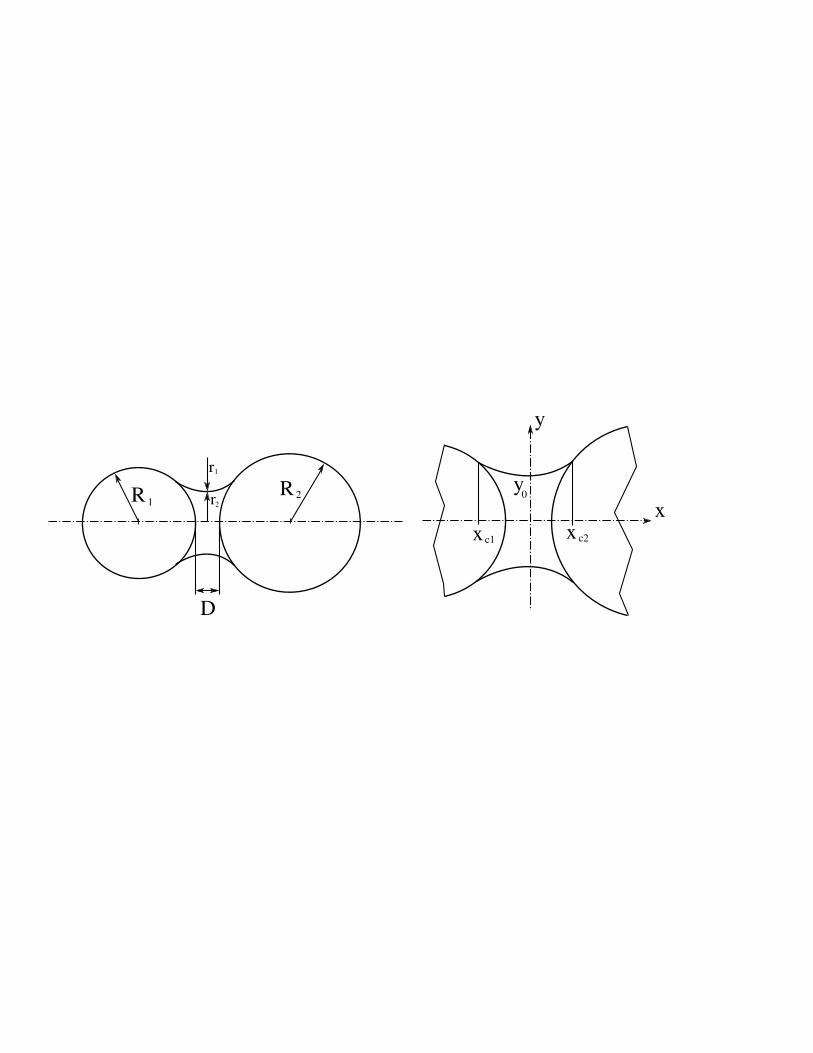
Analytical and experimental results [15,3] demonstrate that cap-illary effects at particle contacts produces a kind of bond between
particles as a result of menisci (Fig.1). Liquid bridges may formbetween some pairs of adjoining particles not necessarily in con-tact, generating an attractive capillary force between the bonded
particles. If the drying process continues, these water bridges be-gin to fail, starting from the non-contacting grains, until the com-
plete disappearance of capillary forces inside the assembly.
As the pendular regime is considered throughout this paper, wa-ter is considered to be solely composed of capillary menisci: eachliquid bridge is assumed to connect only two particles. There-
fore, two types of forces coexist within the granular medium.For dry contacts, a contact force develops between contacting
granules. This repulsive force, that is a function of the relativemotion between the contacting grains, is usually well described
by an elastoplastic contact model. For water bonded particles, aspecific attractive force exists. This water-induced attractive in-
teraction can be described by a resulting capillary force, ratherthan by a stress distribution as mentionned by Haines [15] orFisher [3]. This capillary force is a function of the bridge volume,
of the size of particles, and of the fluid nature (see section 3.1.1for the details). The objective of this section is to derive, in a
simple manner, an expression relating the overall stress tensorwithin the RVE to this internal force distribution.
For this purpose, the Love [16] static homogenisation relationis used. This relation expresses the mean stress tensor σ within
a granular volume V as a function of the external forces ~F ext,p
5
applied to the particles p belonging to the boundary ∂V of thevolume:
σij =1
V
∑
pǫ∂V
F ext,pi xp
j (2)
where xpj are the coordinates of the particle p with respect to a
suitable frame. It is worth noting that this relation is valid what-
ever the nature of the interactions between grains.
Taking into account the mechanical balance of each particle of thevolume V (including the boundary ∂V ), Eq.(2) can be writtenas:
σij =1
V
N∑
p=1
N∑
q=1
F q,pi lq,pj (3)
where N is the number of particles within the volume, ~F q,p isthe interaction force exerted by the particle q onto the particle p,
and ~lq,p is the branch vector pointing from particle q to particlep (~lq,p = ~xp − ~xq).
As we consider partially saturated granular media, two indepen-
dent kinds of interparticle forces can be distinguished:
(i) if particles p and q are in contact, a contact force ~F q,pcont exists.
(ii) if particles p and q are bonded by a liquid bridge, a capillaryforce ~F q,p
cap exists.
Actually, depending on the local geometry, a liquid bond can ex-ist between two grains in contact. In that case, solid contacts
are surrounded by the continuous liquid phase providing the si-multaneity of contact and capillary forces. The two contributionshave therefore to be accounted for by summation.
6
Finally, in all cases and for any couple (p, q)ǫ[1, N ]2, it can bewritten that:
~F q,p = ~F q,pcont + ~F q,p
cap (4)
Thus, by combining Eqs.(2) and (4), it follows that:
σij =1
V
N∑
p=1
N∑
q=1
F q,pcont,il
q,pj +
1
V
N∑
p=1
N∑
q=1
F q,pcap,il
q,pj (5)
As a consequence, Eq.(5) indicates that the stress tensor is splitinto two components:
σij = σcontij + σcap
ij (6)
- A first component σcontij = 1
V
∑Np=1
∑Nq=1 F
q,pcont,il
q,pj accounting
for the contact forces transmitted along the contact network.
- A second component σcapij = 1
V
∑Np=1
∑Nq=1 F
q,pcap,il
q,pj represent-
ing the capillary forces existing within the assembly.
It is to be noted that σcontij is a stress quantity standing for in-
tergranular contact forces in the same way as in saturated ordry conditions. Considering the concept as initially introducedby Terzaghi, σcont
ij plays the role of the so-called effective stress
by governing soil deformation and failure. Besides, σcapij is the ten-
sorial attribute to capillary water effects or suction, by extension.
By analogy with Eq.(1), we can therefore define a microstructuraleffective stress
σcontij = σij − σcap
ij (7)
where σij could be affiliated to net stress, representing the ap-parent stress state in the material. Compared with Eq.(1), wherethe effect of water is intrinsically isotropic, σcap
ij implies a tenso-
rial attribute to the water effects.
In fact, in both terms σcontij and σcap
ij , a fabric tensor can emerge
7
from the summation [16,17,18]. The fabric tensor is useful to char-acterize the contact anisotropy of the assembly, which is known
as a basic feature of granular assemblies. In dry granular materi-als, an induced anisotropy can develop when a deviatoric stressloading is applied. In partially saturated assembly, due to the pos-
sibility of interactions without contact, the conclusion is not sotrivial. As an illustration, if we restrict our analysis to spherical
particles [1], it can be inferred that:
σcapij =
1
V
N∑
p=1
N∑
q=1
F q,pcapl
q,pnp,qi np,q
j (8)
This relation points out that, contrary to the contact term wherethe fabric tensor 1
N
∑Nq=1 n
p,qi np,q
j is directly linked to the induced
anisotropy (a contact is associated with a force), two causes canbe invoked for the capillary term. First, the distribution of the
liquid bonds can be anisotropic. Secondly, the geometry of thebonds being obviously dependent on the local geometry, it is
possible that the distribution of both terms F q,pcap and lq,p is also
anisotropic. This is significant because the anisotropic attributeyields shear effects associated with pore fluid, which could mostly
influence material behaviour.
In order to enrich our discussion, we present numerical investiga-
tions of these features in the following sections using both DEMand micromechanical simulations.
3 MICROSTRUCTURAL INVESTIGATION ON THE CAPIL-
LARY STRESS TENSOR USING DEM
We present here a numerical analysis of the stress variables us-
ing a micromechanical model based upon the Discrete ElementMethod initially introduced by Cundall and Strack [2]. This tech-nique starts with basic constitutive laws between interacting par-
ticles and can provide a macroscopic response of a particle assem-
8
bly due to loading changes at the boundaries. Each particle of thematerial is a rigid sphere identified by its own mass, m, radius,
R and moment of inertia, I0. For every time step of the com-putation, interaction forces between particles, and consequently
resulting forces acting on each of them, are deduced from spherepositions through the interaction law. Newton’s second law is
then integrated through an explicit second order finite differencescheme to compute the new sphere positions.
3.1 The discrete element model
A 3D software called YADE (Yet Another Dynamic Engine), Koz-
icki and Donze [19], has been enhanced in order to properly sim-ulate partially saturated granular material features.
3.1.1 Inter-particle behaviour
The contact interaction is described by an elastic-plastic relationbetween the force F and the relative displacement U of two in-teracting particles. A normal stiffness Kn is therefore defined to
relate the normal force Fn to the intergranular normal relativedisplacement Un :
Fn =
KnUn if Un ≤ 0
0 if Un > 0(9)
and a tangential stiffness Kt allows us to deduce the shear force
Ft induced by the incremental tangential relative displacementdUt; this tangential behaviour obeying the Coulomb friction law:
dFt = −KtdUt
Fmaxt = −µFn
(10)
9
Fig. 1. Illustration of a liquid bridge between two particles of unequal sizes: (a)global geometry, (b) details of the bridge.
where µ is the Coulomb friction coefficient defined as µ = tan(φ),with φ the intergranular friction angle.
In the work presented here, Kn and Kt are dependent functionsof the interacting particle sizes and of a characteristic modulusof the material denoted as E:
Kn = 2E R1R2(R1+R2)
Kt = αKn
(11)
This definition results in a constant ratio between E and the
effective bulk modulus of the packing, whatever the size of theparticles.
For simplicity, we assume that the water inside the sample issolely composed of capillary water as defined in the pendular
state, with a discontinuous liquid phase.
Much attention has been given to these pendular liquid bridges,[20,21,22]. Their exact shape between spherical bodies is defined
by the Laplace equation, relating the pressure difference ∆u =ua − uw across the liquid-gas interface to the mean curvature ofthe bridge and the surface tension of the liquid phase γ:
∆u = γ
(
1
r1+
1
r2
)
(12)
10
In the Cartesian coordinates of Fig.1(b) the two curvature radiir1 and r2 (Fig.1(a)), are given by:
1
r1=
1
y(x)√
1 + y′2(x)(13)
and
1
r2=
y′′(x)
(1 + y′2(x))3/2(14)
where y(x) defines the profile of the liquid-gas interface curve.
The x axis coincides with the axis of symmetry of the bridge,passing through the centers of the connected spheres (Fig.1(b)).According to the Laplace equation, the profile of the liquid bridge
is thus related to the capillary pressure ∆u through the followingdifferential equation:
∆u
γ(1 + y′2(x))3/2 +
1 + y′2(x)
y(x)− y′′(x) = 0 (15)
The corresponding liquid bridge volume V and intergranular dis-tanceD can be obtained by considering the x-coordinates (x1 and
x2) of the three-phases contact lines defining the solid-liquid-gasinterface, as defined by Soulie et al.,[23] :
The capillary force due to the liquid bridge can be calculated
at the profile apex y0 according to the ‘gorge method’ [20] and
11
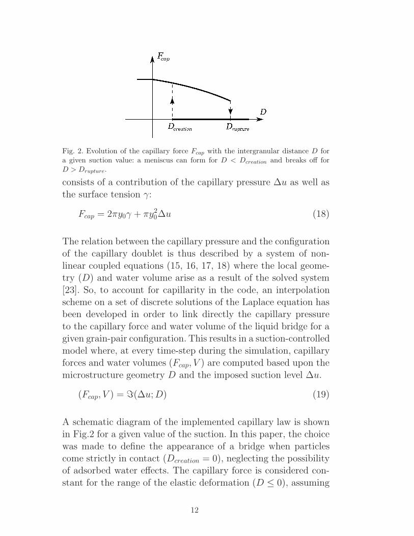
Fig. 2. Evolution of the capillary force Fcap with the intergranular distance D fora given suction value: a meniscus can form for D < Dcreation and breaks off forD > Drupture.
consists of a contribution of the capillary pressure ∆u as well as
the surface tension γ:
Fcap = 2πy0γ + πy20∆u (18)
The relation between the capillary pressure and the configurationof the capillary doublet is thus described by a system of non-
linear coupled equations (15, 16, 17, 18) where the local geome-try (D) and water volume arise as a result of the solved system
[23]. So, to account for capillarity in the code, an interpolationscheme on a set of discrete solutions of the Laplace equation hasbeen developed in order to link directly the capillary pressure
to the capillary force and water volume of the liquid bridge for agiven grain-pair configuration. This results in a suction-controlled
model where, at every time-step during the simulation, capillaryforces and water volumes (Fcap, V ) are computed based upon the
microstructure geometry D and the imposed suction level ∆u.
(Fcap, V ) = ℑ(∆u;D) (19)
A schematic diagram of the implemented capillary law is shownin Fig.2 for a given value of the suction. In this paper, the choice
was made to define the appearance of a bridge when particlescome strictly in contact (Dcreation = 0), neglecting the possibilityof adsorbed water effects. The capillary force is considered con-
stant for the range of the elastic deformation (D ≤ 0), assuming
12
local displacements to be very small compared to particle radii.Let us note that the formulation intrinsically defines the distance
from which the meniscus breaks off as depending on the givencapillary pressure and on the local geometry. This maximum dis-
tance Drupture corresponds to the minimum D value from whichthe Laplace equation has no solution.
3.1.2 Stress tensors
Since this study covers the macroscopic and microscopic aspectsof unsaturated granular media, stress tensors are calculated by
both macro and micro-methods. The macro-method is the con-ventional way used in laboratory to measure stresses in experi-ments, that is to say:
σij = (∑
Fi)/Sj (20)
where Fi is the normal force acting on the boundary, and Sj thesurface of the boundary oriented by the normal direction j. Thisstress is equivalent to net stress (σij − uaδij) used in unsaturated
soils mechanics, with ua used as the reference pressure becausethe pore air pressure is effectively zero in many practical prob-
lems (as well as in this study).
As seen in section 2.2, two other stress tensors can be considered
through homogenization techniques: the intergranular stress ten-sor σcont computed from intergranular forces, and the capillary
stress tensor σcapij computed from capillary forces.
3.1.3 Sample description and testing programme
The studied particle assembly is a 1 mm length cubic sample
composed of 10000 spheres, with a grain size distribution rangingfrom 0.025 mm to 0.08 mm, as shown in Fig.3, and a porosityof 0.385. The input parameters are listed in table 1, referring to
equation (10).
13
Global Modulus Kt
KnFriction angle
E (MPa) α φ (deg.)
150 0.5 30
Table 1DEM model parameters
Fig. 3. Sample description.
The sample was prepared by an isotropic-compaction technique,
which can be described in two stages.
(a) All particles are randomly positioned inside a cube made upof 6 rigid walls in such a manner that no overlap/contact force
develops between any pair of particles. The interparticle fric-tion angle is set to a small value (the smaller the friction angle,
the denser the assembly. A value of 0.2 degree has been cho-sen here) and particle radii are then homogeneously increased,
whereas boundary walls stay fixed. The process is run until theconfining pressure (15 kPa) is reached and equilibrium between
the internal stress state and the external load is satisfied [24].(b) The interparticle friction coefficient is then changed to a value
classically used in DEM simulation to reproduce an accept-
able shear strength (30 degree) and boundary walls are servo-
14
controlled in displacement to keep the equilibrium state.
Starting from the initially stable configuration, a given suction is
then applied. In this case, capillary forces (Eq.(18)) are added toall existing contact forces (Dcreation = 0, see figure 2). This pro-
cess simulates the appearance of liquid bridges at body contactsas it would take place during a capillary condensation when the
relative humidity of the surrounding air is increased, and coin-cides with a wetting of the material. The sample then reaches a
new equilibium state from which different stress paths can be im-posed. Note that capillary forces are assumed to be zero betweena sphere and a wall.
Suction-controlled triaxial compression tests have been carried
out on the generated specimen which was taken up from the ini-tial state of 15 kPa to upper confining pressures by isotropic com-
paction through wall displacements. The capillary pressure value(10 kPa) has been chosen so as liquid bridge volumes are smallenough to avoid the possibility of interconnected liquid bridges,
and hence to ensure the pendular regime in the medium. Thewater content can be simply computed as the sum of all the liq-
uid bridge volumes. In this case, the associated initial degree ofsaturation of the sample is about 20%. A constant compression
rate is then applied in the axial direction, controlling the lateralwalls in displacement to keep the confining pressure constant.
To keep the quasi-static assumption, the loading rate was fixedsufficiently small so as the normalized mean resultant force onparticles (which is 0 at static equilibrium) does not exceed 1%
at each loading step.
15
Fig. 4. Axial stresses resulting from elastic forces (σcont) and capillary forces (σcap),as well as the external load on the wall (σwall) under a suction-controlled triaxialcompression.
3.2 Stress tensor analysis
3.2.1 Macroscopic evidence for the capillary stress tensor
The quasi-static assumption ensures the equilibrium of the in-
ternal stress state and external load to be satisfied over everyloading path. The internal stress has therefore to be the sum of
the repulsive stress due to the elastic forces Fn and the tensileone due to the capillary forces Fcap, as presented by Eq.(6) in
subsection 2.2.
σij = σcontij + σcap
ij (21)
As shown in figure 4 for a triaxial loading path under a given
confining pressure of 15kPa, this additivity is perfectly verified.The quasi-static assumption is numerically confirmed and theexistence of a capillary stress tensor is therefore proved for the
case of wet granular materials.
16
Fig. 5. Evolution of the principal capillary stress tensor components during a suc-tion-controlled triaxial compression test (P0 = 15kPa, u = 10kPa).
3.2.2 Capillary stress tensor analysis
This suction induced stress leads to some questions about its
structure and more generally on water distribution inside thematerial. In fact, classical considerations of unsaturated mate-
rials often assimilate suction effects to an equivalent pressurewhich consequently acts in the medium independently from itsanisotropy (the ”hydraulic” component of the effective stress is
generally considered as an isotropic tensor).
Computing the principal components of this capillary stress ten-sor along the deviatoric loading path of a triaxial test compro-
mises this assumption as shown in Fig.5. This is all the moreremarkable in that the model ensures a uniform distribution of
the capillary pressure inside the medium. It is clear that for theinitial state corresponding to an isotropic configuration of the
assembly, the capillary stress tensor is almost spherical with aninitial mean value of about 3.6 kPa for both axial and lateral
components. Nevertheless, the anisotropy rapidly evolves withthe one induced by loading, providing a difference between theprincipal components. If we define α = 2 σcap
1−σcap
2
(σcap1
+σcap2
)as a represen-
tative index of the tensor sphericity: α = 0 for the initial isotropic
17
Fig. 6. Evolutions of the porosity and average number of contacts by particles Kunder a suction-controlled triaxial compression (P0 = 15 kPa, u = 10 kPa).
state, and then slightly evolves to a quasi-constant value of 0.12from the 7% deformation level until the final 15% computedstate.
The causes of this evolution can be analysed by examining the
volumetric deformation of the sample (Fig.6(a)) and the associ-ated packing rearrangement through the average number of con-
tacts by particle, K, (Fig.6(b)). As these global considerationshave to be completed by a micromechanical analysis in order to
gain a clear insight into the microstructural origins of the phe-nomenon, Fig.6 will be commented in the following section.
3.2.3 Micromechanical investigation
Here we develop a micromechanical analysis of the stress vari-ables by considering both contact and liquid bridge distributions
through the whole assembly. As the local interactions (dry con-tacts or menisci interactions) involve normal directions, a database
can be defined in terms of orientations for all the grains of thesample. It is proposed to examine this normal direction network.
The search has been done considering the given direction angleθ as presented in Fig.7, with θ corresponding to the angle of
the unit normal vector (~n) from the axis of axisymmetry of the
18
Fig. 7. Description of the method used for interaction orientation distribution.
sample (Y ). As seen in section 2.2, σcapij can be written as:
σcapij =
1
V
N∑
p=1
N∑
q=1
F q,pcapl
q,pnp,qi np,q
j (22)
which points out the possible induced anisotropy of the capil-lary tensor by means of both liquid bridge and force intensity
distributions. If we now introduce Pmeniscus(~n) as the menisci ori-entation distribution inside the sample (in fact, the number of
menisci along the direction ~n) defined by∫
V Pmeniscus(~n)dV = 1,Eq.(22) becomes:
σcapij =
1
V
∫
V
< Fcap.l >~n Pmeniscus(~n)~n⊗ ~ndV (23)
where < Fcap.l >~n is the mean value of ~Fcap.~l along the direc-tion ~n. It is therefore possible to compute separately the geomet-
ric distribution (Pmeniscus(~n)) and the static distribution of the(< Fcap.l >~n) quantity which involves the mean force intensity,
for every direction characterized by ~n.
P (~n) (Fig.8) and < F.l >~n (fig.9) distributions with θ are plotted
for several deformation levels for both contacts and menisci con-
19
Fig. 8. Contacts and menisci orientation distribution P (~n) for different deformationlevels
tributions. < Fcont.l >~n and < Fcap.l >~n are simply normalizedby their mean value to be qualitatively compared. The searchhas been done for different deformation levels on the sample con-
fined under 15 kPa and subjected to a constant capillary pressureof 10 kPa. Different snapshots have been taken, starting from
the assumed isotropic initial state, until a 15% axial strain levelwhere the deformation regime appears almost permanent. First,
as menisci are added at contacts to simulate capillary condensa-tion, distributions of both contact and capillary terms are iden-
tical in the initial state. The structural isotropy of the sampleclearly appears with a uniform distribution of P (~n) and < f.l >~n
for contacts and menisci along all the directions (Figs.8(a) and
9(a)), confirming here the accuracy of the generation process.
20
The evolutions of both contact and liquid bridge distributions
during the loading directly results from the deformations of theassembly. As the sample reacts just like a dense granular material
(Fig.6(a)), the initial contractancy gives rise to a brief increase inthe coordination number (Fig.6(b)), leading to the developmentof new liquid bridges. The corresponding growth of both axial
and lateral capillary stress components can be viewed on Fig.5.As a consequence of the persistance of menisci for low interparti-
cle distances, this combined augmentation persists until ǫ1 = 3%even if K strongly drops before rising up again. The small dif-
ference between the axial and the lateral components is simplydue to the deviatoric loading which produces more contacts, and
consequently more menisci, in the active loading direction (Y )than in the passive stress-controlled one.
After ǫ1 = 3%, the lateral capillary tensor component clearlystarts to reduce. As pointed out in Fig.8(b), this results fromthe lateral spreading of the particles produced by the dilatancy
of the assembly. Even though menisci distribution Pmeniscus(~n)seems not to follow the induced fabric anisotropy because of the
remaining of the liquid bridges, lateral capillary forces tend todiminish due to increasing interparticular distances (Fig.2). On
the other hand, the axial component of the capillary stress ten-sor regularly rises until the initiation of a permanent regime in
the deformation process (near ǫ1 = 7%) where K continues ongoing quasi-constant. From this state, as the number of contactsstabilizes while dilatancy persists, < Fcap.l >~n cannot endure any
further increase and the axial component of the capillary tensorstarts to diminish because of a higher spreading of the grains.
Describing the fabric induced anisotropy, Pcont(~n) distributionfrom 3 to 15%, seems to be quite constant. However, it can be
noted that < Fcont.l >~n contribution appears to reach rapidly a
21
Fig. 9. Contacts and capillary forces distribution orientations (< F.l >~n) for differ-ent deformation levels
maximum anisotropic state before slightly reducing to the finalone. This maximum anisotropic strength state fairly corresponds
to the peak shear strength of the sample (ǫ1 = 3%) where verti-cal contact force chains are subjected to maximum loading before
breaking off. Concerning the final distributions, they are well rep-resentative of the so-called critical state, where a stabilization of
the stresses occurs with no new significative change in the evolu-tion of the anisotropy. In a noteworthy way, menisci seem not to
follow the same evolution. Effectively, as liquid bridges can ex-ist in a certain range of increasing intergranular distances, theirdistribution in the media is not driven in the same way by the fab-
ric induced anisotropy and tends to stay close to the initial state,
22
particularly for the range of small deformations. Nevertheless, forlarge deformations,due to the sample dilatancy, a small induced
anisotropy arises from the disappearance of liquid bridges in thelateral directions. It is evident that the history of the material is
fundamentally essential when dealing with water distribution.
To sum up, the analysis reveals a slight induced anisotropy of
the capillary stress tensor as a function of the medium fabric.The pore fluid in unsaturated soil has its own fabric that may
be readily altered with changes in the granular fabric and is alsostrongly dependent on the water distribution inside the media.The global approximation which characterizes water effects in
unsaturated materials by an equivalent pore pressure is, there-fore, unable in essence to point out this intrinsically anisotropic
microstructural force contribution. However, depending on thehydric history, the evolving anisotropy of the pore water distri-
bution can validate the assumption by counterbalancing the in-duced fabric anisotropy in the material.
Since DEM analyses result from direct simulations of a granularassembly, the purpose of the next section is to compare the re-
sults with those of a microstructural model where the behaviourof the material is obtained through a micromechanically basedconstitutive relation.
4 COMPARISON WITH A MICRO-MECHANICAL MODEL
In this section, we first present the microstructural model used
to compare with DEM simulations. This is a stress-strain model([25,26,1]) proposed by Chang and Hicher [27] which considers
inter-particle forces and displacements. Its capability has beenrecently extended to unsaturated states by incorporating the in-fluence of capillary forces at the micro level [10]. By comparing
the predicted triaxial loading results obtained by the two ap-
23
proaches for the granular assembly of section 3, we confirm thestress conceptions introduced previously, focusing on the capil-
lary stress tensor as defined in section 2.2.
4.1 Stress-Strain Model
In this model, we envision a granular material as a collection
of particles. The deformation of a representative volume of thismaterial is generated by the mobilisation of contact particles in
all orientations. Thus, the stress-strain relationship can be de-rived as an average of the mobilisation behaviour of local contact
planes in all orientations. The forces and movements at the con-tact planes of all orientations are suitably superimposed to obtainthe macroscopic stress strain tensors using the static homogeniza-
tion presented in Section 2.2.
4.1.1 Inter-particle behaviour
- Contact forces and capillary forces
For dry samples, contact forces are directly determined from theexternal stresses σ applied on the granular assembly (Eq.(2)). In
the case of wetted samples, different stages of saturation can beidentified. The fully saturated regime corresponds to a two-phasematerial with water filling completely the voids between grains.
The water pressure uw can either be positive or negative (suction)but in both cases the effective stress concept [4] can be applied
and the contact forces determined by considering the effectivestresses σ′ as the external stresses ([28,29]):
σ′ = σ − uwI (24)
As seen previously, in the case of partially saturated samples inthe pendular regime, the liquid phase is distributed in menisci lo-cated between close grains. As a consequence, capillary forces are
applied on the grains and are added to the contact forces defined
24
above. The attractive capillary force between two grains con-nected by a water bridge is a decreasing function of the distance
between the grains until the bridge fails (Fig.2). This function de-pends on the volume of liquid found between the grains. Different
mathematical expressions have been proposed for these capillaryforces, Fcap. Eq.(18) presents the expression used in DEM. Fcap
depends on the capillary pressure defined as the pressure jumpacross the liquid-air interface, on the liquid-air interface surface
tension, as well as on the geometry of the menisci governed by thesolid-liquid contact angle and the filling angle. One can see thatFcap depends on the geometry of the liquid bridge which is func-
tion of the amount of the pore water and of the distance betweentwo neighboring grains. The use of Eq.(18) for determining the
amplitude of the capillary forces is not a straightforward one andtherefore, in the micro-mechanical model, a simplified approach
is to consider an empirical relation between Fmax and the degreeof saturation Sr:
F ncap = Fmaxe
−c(DR) (25)
where F ncap is the capillary force between two neighbouring grains,
not necessarily in contact, Fmax the value of Fncap for two grains in
contact and R the mean grain radius. D represents the distance
between two grains and is equal to l − 2R, l being the branchlength given as a distribution function of the grain size and the
void ratio and c is a material parameter, dependent on the grainmorphology and on the water content:
Fmax = F0Sr
S0
for 0 < Sr < S0
Fmax = F0S0(1−Sr)Sr(1−S0)
for S0 < Sr < 0(26)
where F0 and S0 are material parameters. F0 depends on thegrain size distribution, S0 represents the degree of saturation atwhich any further drying of the specimen will cause substantial
breaking of the menisci in the pendular domain. S0 depends on
25
the nature of the granular material.
Since the menisci are not necessarily all formed in the funicular
regime, Eq.(25) may not be applicable for high degrees of satura-tion. However, in this first approach, we decided to extend it to
the whole range of saturation, considering that the amplitudes ofcapillary forces were small for degrees of saturation higher that
80% and could thus be approached with sufficient accuracy byusing the same equation.
- Elastic relationship
The contact stiffness of a contact plane includes normal stiffness,kαn , and shear stiffness, kαt . The elastic stiffness tensor is defined
by
F αi = kαeij δ
αej (27)
which can be related to the contact normal and shear stiffness by
kαeij = kαnnαi n
αj + kαt (s
αi s
αj + tαi t
αj ) (28)
The value of the stiffness for two elastic spheres can be estimatedfrom Hertz-Mindlin’s fomulation. For sand grains, a revised formwas adopted [30], given by
kn = kn0(Fn
Ggl2)n kt = kt0(
Fn
Ggl2)n (29)
where Gg is the elastic modulus for the grains, Fn is the contactforce in normal direction, l is the branch length between the two
particles, kn0, kt0 and n are material constants.
- Plastic relationship
Plastic sliding often occurs along the tangential direction of the
contact plane with an upward or downward movement, thus shear
26
dilation/contraction takes place. The dilatancy effect can be de-scribed by
dδpnd∆p
=T
Fn− tanφ0 (30)
where φ0 is a material constant which, in most cases, can be con-
sidered equal to the internal friction angle φµ. This equation canbe derived by equating the dissipation work due to plastic move-
ments and friction in the same orientation. Note that the shearforce T and the rate of plastic sliding d∆p can be defined as
T =√
F 2s + F 2
t and d∆p =√
(dδps)2 + (dδpt )2. The yield func-tion is assumed to be of the Mohr-Coulomb type,
F (Fi, κ) = T − Fnκ(∆p) = 0 (31)
where κ(∆p) is an isotropic hardening/softening parameter de-
fined as:
κ =kp0tan(φp)∆
p
|Fn|tan(φp) + kp0∆p(32)
The hardening function is defined by a hyperbolic curve in κ−∆p
plane, which involves two material constants: φp and κp0. On theyield surface, under a loading condition, the shear plastic flow
is determined by a normality rule applied to the yield function.However, the plastic flow in the direction normal to the contact
plane is governed by the stress-dilatancy equation in Eq.(32).Thus, the flow rule is non-associated.
- Interlocking influence
The internal friction angle φµ is a constant for the material. How-
ever, the peak friction angle, φp, on a contact plane is dependenton the degree of interlocking by neighboring particles, which can
be related to the state of the packing void ratio e by:
tan(φp) = (ece)mtan(φµ) (33)
27
where m is a material constant [31]. The state of packing is itselfrelated to the void ratio at critical state ec. The critical void
ratio ec is a function of the mean stress. The relationship hastraditionally been written as:
ec = Γ− λlog(p′) or ec = eref − λlog(p′
pref) (34)
where Γ and λ are two material constants and p′ is the mean
stress of the packing, and (eref , pref) is a reference point on thecritical state line.
For dense packing, the peak frictional angle φp is greater than φµ.When the packing structure dilates, the degree of interlocking and
the peak frictional angle are reduced, which results in a strain-softening phenomenon.
- Elasto-plastic relationship
With the elements discussed above, the final incremental stress-strain relations of the material can be derived that includes both
elastic and plastic behaviour, given by F αi = kαpij δ
αj . Detailed
expression of the elasto-plastic stiffness tensor is given in [27].
4.1.2 Stress-strain relationship
- Macro micro relationship
The stress-strain relationship for an assembly can be determinedfrom integrating the behaviour of inter-particle contacts in all
orientations. During the integration process, a relationship is re-quired to link the macro and micro variables. Using the static
hypotheses proposed by Liao et. al [32], we obtain the relationbetween the macro strain and inter-particle displacement (finitestrain condition not being considered here):
ui,j = A−1ik
N∑
α=1
δαj lαk (35)
28
where δαj is the relative displacement between two contact parti-cles and the branch vector lk is the vector joining the centers of
two contacting particles.
Using both the principle of energy balance and Eq.(36), the meanforce on the contact plane of each orientation is
F αi = σijA
−1jk l
αkV (36)
The stress increment σij induced by the loading can then be ob-tained through the contact forces and branch vectors for contacts
in all orientations [17,18]. Since lαk represents the mean branchvector for the αth orientation including both contact and non-
contact particles, the value of F αi in Eq.(37) represents the mean
of contact forces in the αth orientation.
σij =1
V
N∑
α=1
F αi l
αj (37)
When the defined contact force is applied in Eq.(37), Eq.(38) is
unconditionally satisfied.
Using the definition of Eq.(38), the stress induced by capillary
forces can be computed and is termed as capillary stress, givenby
σcapij =
1
V
N∑
α=1F αcap,il
αj (38)
As mentionned in section 2.2, it is noted that this term is not anal-ogous to the usual concept of capillary pressure or suction which
represents the negative pore water pressure inside the unsatu-rated material. In agreement with the results obtained through
DEM simulations, the capillary stress depends on the geometryof the pores and is a tensor rather than a scalar. Only for anisotropic distribution of the branch lengths lα, this water associ-
ated stress can be reduced to an isotropic tensor. This is the case
29
for an initially isotropic structure during isotropic loading, butduring deviatoric loading, an induced anisotropy is created and
the capillary tensor is no longer isotropic.
At the equilibrium state, the effective intergranular forces willtherefore be the difference between the repulsive forces due to
the external stresses (Eq.(38)) and the attractive capillary forces(Eq.(39)). In a similar way to Eq.(7), we can thus define a gen-
eralized intergranular stress tensor σ∗, defined by:
σ∗ = σ − σcap (39)
Assuming that σ∗ can stand as an appropriate definition of the
effective stress, this equation could represent a generalisation ofEq.(1) proposed by Bishop, in which the capillary stress is re-
duced to an isotropic tensor. Dangla et al. [33] demonstrated thevalidity of the effective stress approach in elasticity by means
of an energy approach. They obtained an expression similar toEq.(40) but with an additional term corresponding to the work
of the interfaces. As pointed out before, capillary forces in ourmodels, and consequently the capillary stresses, depend on thenegative pore water pressure, or suction, and on the water-air
interface surface tension. A similar approach can be found in thework of Fleureau and al. [34] who obtained an explicit expres-
sion of the capillary stress as a function of the suction for regulararrangements of spherical grains by neglecting the surface ten-
sion. The definition of the capillary stress tensor in Eq.(39) cantherefore be considered as an extension of the results obtainedfrom these previous studies to cases of non isotropic granular
assemblies.
4.1.3 Summary of parameters
One can summarize the material parameters as:
- Normalized contact number per unit volume: Nl3
V .
30
- mean particle size, 2R.- Inter-particle elastic constants: kn0, kt0 and n.
- Inter-particle friction angle: φµ and m.- Inter-particle hardening rule: kp0 and φ0.
- Critical state for packing: λ and Γ or eref and pref .- Capillary force equation: f0, S0 and c.
Other than critical state parameters, all parameters are inter-
particles. Standard values for kp0 and φ0 are the following: kp0 =kn0 and φ0 = φµ and a typical ratio kt0
kn0= 0.4 can generally
be assumed [10]. Therefore, for dry or saturated samples, onlysix parameters have to come from experimental results and these
can all be determined from the stress-strain curves obtained fromdrained or undrained compression triaxial tests. For unsaturatedstates, three more parameters need to be determined, using spe-
cific triaxial tests on partially saturated samples.
4.2 Numerical simulations
Several simulations of triaxial loading have been performed in or-
der to compare DEM and Micromechanical Model results. Theseare based on computations on a Representative Volume Elementof about 10 000 spherical elements.
4.2.1 Dry samples
The model parameters were determined from the following pro-cedure. The granular assembly defined in the discrete element
model is made of spherical particles with the grain size distribu-tion presented in Fig.3. The particle size 2R was selected equal
to d50 = 0.045mm. The elastic parameters could not be directlyderived from the inter-particle behaviour used in the DEM sim-
ulations, which consider a linear contact stiffness. From previ-ous studies on glass beads assemblies [35,10], typical values wereadopted in this study. The plastic parameters were determined
from the numerical results obtained by DEM. Table II summa-
31
rizes the set of parameters used for modelling the dry samplebehaviour.
kn0 (N/m) kt0kn0
n φµ (deg.) λ m
300 0.5 30 20 0.05 0.5
Table 2Microstructural Model parameters for the glass beads assembly
Fig.10 presents the numerical simulations of three triaxial tests
performed at three different confining pressures of 15, 30 and60 kPa for the simulated dry assembly having an initial void ra-
tio equal to 0.38. One can see that the results obtained with theMicrostructural Model compared well to DEM ones.
4.2.2 Wet samples
DEM simulations were performed on unsaturated assemblies withan initial saturation degree of about 20%, corresponding to a suc-tion value equal to 10 kPa. In order to determine the correspond-
ing capillary forces, Eq.(25) includes two material parameters cand d which control the evolution of the water induced forces with
the distance between two particles. According to experimental re-sults presented in different studies [21,23], we decided to take a
value of c = 4 and of d = 0.05mm. These values give a standardevolution for the capillary forces, function of the distance between
particles, as well as an initial isotropic distribution of these forcesif the material structure is isotropic. The evolution of the capil-lary forces with the degree of saturation requires two more param-
eters: S0 and f0. According to previous studies [10], we selecteda value of S0 = 1% and determined the value of f0 = 0.045N .
In order to obtain an initial value of the capillary stress in ac-cordance with the one computed by DEM. We then performed
numerical simulations of triaxial tests on wet samples for dif-ferent confining pressures. Contrary to DEM suction-controlled
simulations, the Microstructural Model tests are water contentcontrolled. In order to compare those two approaches, sampleswere initially wetted at a common degree of saturation of about
20%. One should notice that, even if the test conditions are not
32
Fig. 10. DEM and MicroMechanical simulations of triaxial compression tests on asimilar dry granular assembly.
strictly identical, the changes in the degree of saturation dur-ing loading obtained for both tests are sufficiently similar for us
(Fig.11) to compare the results obtained by the two approaches.
As presented in Fig.12, the two models give quite similar results.One can see that a material strength increase is obtained for un-
saturated samples compared to dry ones at the same confiningpressure. The volume changes during triaxial loading create asmall change in the degree of saturation (Fig.11). As a conse-
quence, the capillary forces evolve, according to Eq.(5). Fig.13
33
Fig. 11. Evolution of the saturation degree during DEM and Micromechanical sim-ulated triaxial tests.
shows the evolution of the principal components of the capillarystress tensor during constant water content triaxial tests. The
initial state corresponds to an isotropic capillary stress tensorwith a mean stress equal to 3.6 kPa as obtained in DEM. Duringloading, a structural anisotropy is created due to the evolution
of the fabric tensor defined in Eq.(38). Therefore, the principalcomponents of the capillary stress tensor evolve differently. In
the studied cases, this difference remains small and correspondsat the end of the test to a relative difference less than 10%. This
small difference can be explained by two causes. The first one isthe small amount of induced anisotropy obtained by the evolution
of the fabric tensor. This evolution is due to the change in thebranch length lαi for each α direction which, in this version of themodel, is only due to elastic deformations of the grains in contact.
Since all our numerical testing were performed at small confin-ing stresses, the amount of elastic deformation remained quite
small. The second reason is linked to the fact that the capillarybridges can exist for non-touching neighboring grains. This has
been taken into account in calculating the mean capillary forceand also in determining the capillary stress tensor (Eqs.(27) and
(41)). This result is in agreement with the distribution of thecontacts and menisci distribution computed by DEM (Figs.8 and9).
34
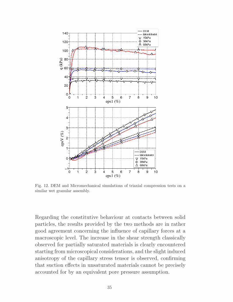
Fig. 12. DEM and Micromechanical simulations of triaxial compression tests on asimilar wet granular assembly.
Regarding the constitutive behaviour at contacts between solid
particles, the results provided by the two methods are in rathergood agreement concerning the influence of capillary forces at a
macroscopic level. The increase in the shear strength classicallyobserved for partially saturated materials is clearly encountered
starting from microscopical considerations, and the slight inducedanisotropy of the capillary stress tensor is observed, confirmingthat suction effects in unsaturated materials cannot be precisely
accounted for by an equivalent pore pressure assumption.
35
Fig. 13. Evolution of the principal capillary stress tensor components during a tri-axial compression test on a wet granular assembly.
5 CONCLUSION
Starting from local capillary forces, a stress variable, denoted
as the capillary stress tensor and intrinsically associated to wa-ter effects, has been defined through homogenisation techniques.
Triaxial compression test simulations from two fundamentallydifferent micromechanical models were performed on a granu-
lar assembly under several confining pressures for dry and par-tially saturated conditions. Both models reproduce in quite good
agreement the main features of unsaturated granular materials,in particular the increase of the shear strength due to capillaryeffects.
The results also suggest that, in partially saturated materialswithin the pendular regime, the effects of pore fluid are ade-
quately represented by a discrete distribution of forces ratherthan by an averaged pressure in the fluid phase. Effectively, as a
representative quantity of the pore fluid distribution inside unsat-urated materials, this suction associated stress tensor reveals that
pore fluid has its own fabric which is inherently anisotropic andstrongly dependent on the combined loading and hydric historyof the material. Even if the induced anisotropy of the capillary
stress tensor appears slight in this study, it is obvious that this
36
tensorial nature of water in unsaturated material implies suc-tion to produce shear effects on the solid phase. This suction in-
duced shear effect consequently makes it difficult to associate anisotropic quantity to water as expressed in the Bishop’s effective
stress. Pore pressure is no longer an isotropic stress in unsatu-rated soil, and therefore, cannot be considered as an equivalent
continuum medium. The analysis finally confirms that suction isa pore-scale concept, and that stress definitions for unsaturated
soils should also include microscopic interparticle stresses as theones resulting from capillary forces.The multi-scale approach presented here appears to be a perti-
nent complementary tool for the study of unsaturated soil me-chanics. More precisely, discrete methods should convey new in-
sights into the discussion about the controversial concept of gen-eralized effective stress by relating basic physical aspects to clas-
sical phenomenological views.
References
[1] Nicot F, Darve F. A multiscale approach to granular materials. Mechanics ofmaterials 2005; 37(9):980-1006.
[2] Cundall PA, Strack ODL. A discrete numerical model for granular assemblies.Geotechnique 1979; 29(1):47-65.
[3] Fisher RA. On the capillarity forces in an ideal soil; correction of formulae givenby W.B. Haines. Journal of Agricultural Science 1926; 16:492-505.
[4] Terzaghi K. Principles of soil mechanics, a summary of experimental results ofclay and sand. Engineering New Record, 1925; 3-98.
[5] Bishop AW. The principle of effective stress. Tecnisk Ukelab 1959; 39:859-863.
[6] Fredlund DG, Morgenstern RR, Widger RA. The shear strength of unsaturatedsoils. Canadian Geotechnical Journal 1978; 15(3):313-321.
[7] Li XS. Effective stress in unsaturated soil: A microstructural analysis.Geotechnique 2003; 53:273-277.
[8] Jiang MJ, Leroueil S, Konrad JM. Insight into shear strength functions ofunsaturated granulates by DEM analyses. Computers and Geotechnics 2004;31:473-489.
37
[9] Lu N, Likos WJ. Suction stress characteristic curve for unsaturated soil. J. ofGeotechnical and Geoenvironmental Engineering 2006; 132(2):1090-0241.
[10] Hicher P-Y, Chang CS. A microstructural elastoplastic model for unsaturatedgranular materials. Int. Journal of Solids and Structures 2007; 44:2304-2323.
[11] Nuth M, Laloui L. Effective stress concept in unsaturated soils: clarificationand validation of a unified framework. Int. Journal for Numerical and AnalyticalMethods in Geomechanics 2008; 32:771-801.
[12] Alonso EE, Gens A, Hight DW. A constitutive model for partially saturatedsoils. Geotechnique 1990; 40(3):405-430.
[13] Wheeler SJ, Sivakumar V. An elasto-plastic critical state framework forunsaturated soils. Geotechnique 1945; 45(1):35-53.
[14] Bishop AW, Blight GE. Somme aspects of effective stress in saturated andpartly saturated soils. Geotechnique 1963; 13(3):177-197.
[15] Haines WB. Studies of the physical properties of soils. II A note on the cohesiondeveloped by capillarity forces in an ideal soil. Journal of Agricultural Science1925; 15:529-535.
[16] Love AEH. A treatise on the mathematical theory of elasticity. CambridgeUniversity Press, Cambridge, 1927.
[17] Christofferson J, Mehrabadi MM, Nemat-Nassar S. A micromechanicaldescription on granular material behaviour. ASME Journal of Applied Mechanics1981; 48:339-344.
[18] Rothenburg L, Selvadurai APS. Micromechanical definition of the Cauchy stresstensor for particulate media. Mechanics of structured media 1981; SelvaduraiA.P.S. editor. Amsterdam, The Netherlands: Elsevier. 469-486
[19] Kozicki J, Donze FV. A new open-source software using a discrete elementmethod to simulate granular material. Computer Methods in Applied Mechanicsand Engineering 2008; 197:4429-4443.
[20] Hotta K, Takeda K, Ionya K. The capillary binding force of a liquid bridge.Powder Technology 1974; 10:231-242.
[21] Lian G, Thornton C, Adams MJ. A theoritical study of the liquid bridge forcebetween rigid spherical bodies. Journal of Colloid an Interface Science 1993;161:138-147.
[22] Willet CD, Adams MJ, Simon AJ, Seville JPK. Capillary bridges between twospherical bodies. Langmuir 2000; 16:9396-9405.
[23] Soulie F, Cherblanc F, El Youssoufi MS, Saix C. Influence of liquid bridges onthe mechanical behaviour of polydisperse granular materials. Int. Journal forNumerical and Analytical Methods in Geomechanics 2006; 30:213-228.
38
[24] Mahboubi A, Ghaouti A, Cambou B. La simulation numrique discrete ducomportement des materiaux granulaires. Revue Francaise de Geotechnique1996; 76:45-61.
[25] Cambou B, Jafari K. A constitutive model for non-cohesive soils. Computer andGeotechnics 1989; 7(4):341-359.
[26] Sia Nemat-Nasser. A micro-mechanically based constitutive model for frictionaldeformation of granular materials. Journal of the Mechanics and Physics ofSolids 2000; 48:1541-1563.
[27] Chang CS, Hicher P-Y. An elastoplastic model for granular materials withmicrostructural consideration. Int. Journal of Solids and Structures 2005;42(12):4258-4277.
[28] De Buhan P and Dormieux L. On the validity of the effective stress concept forassessing the strength of saturated porous materials: a homogenization approach.Journal of the Mech. and Phys. of Solids 1996; 44(10):1649-1667.
[29] Hicher P-Y. Experimental behaviour of granular materials. In Cambou, B. (Ed.)Behavior of granular materials 1998; Springer, Wien New York; 1-97.
[30] Chang CS, Sundaram SS, Misra A. Initial moduli of particulate mass withfrictional contacts. Int. Journal for Numerical and Analytical Methods inGeomechanics 1989; 13(6):626-641.
[31] Biarez J, Hicher P-Y. Elementary Mechanics of Soil Behaviour. Balkema,Rotterdam; 1994, p. 208.
[32] Liao CL, Chang TP, Young D, Chang CS. Stress-strain relationship for granularmaterials bases on hypothesis of best fit. Int. Journal of Solids and Structures1997; 34:4087-4100.
[33] Dangla P, Coussy O, Eymard R. Non-linear poroelasticity for unsaturatedporous materials: an energy approach. Poromechanics, a tribute to M.A. Biot.Proceedings of the Biot Conference on Poromechanics, Balkema, 1998; 59-64.
[34] Fleureau J-M, Hadiwardoyo S, Gomes Correia A. Generalised efective stressanalysis of strength and small strains behaviour of a silty sand, from dry tosaturated state. Soils and Foundations 2003; 43(4):21-33.
[35] Hicher P-Y. Elastic properties of soils. Journal of Geotechnical EngineeringASCE, 1996; 122(8): 641-648.


![Index [researchonline.jcu.edu.au]...Cantilever sheet piles, 385-395 in cohesive :3-oiis, 393-395 in granular s.oils, 386-393 hortzontal bading, 225. 226 Capillary effects, 68-69. 70](https://static.documents.pub/doc/80x56/5e83cbc841712f77af2c376b/index-cantilever-sheet-piles-385-395-in-cohesive-3-oiis-393-395-in-granular.jpg)


![Capillary thermostatting in capillary electrophoresis · Capillary thermostatting in capillary electrophoresis ... 75 µm BF 3 Injection: ... 25-µm id BF 5 capillary. Voltage [kV]](https://static.documents.pub/doc/80x56/5c176ff509d3f27a578bf33a/capillary-thermostatting-in-capillary-electrophoresis-capillary-thermostatting.jpg)


![Capillary interaction in wet granular assemblies: Part 2 · terized by increasing saturation: pendular, funicular, capillary and slurry [26, 45]. The pendular state is characterized](https://static.documents.pub/doc/80x56/5f706940207dc95a941b8cb6/capillary-interaction-in-wet-granular-assemblies-part-2-terized-by-increasing-saturation.jpg)


