qb J R. & M° No. 3731 ,~, ~ i,.., E l ., !i, ,~ i~ : I ' ,,,i I' ,l~,i ¸'¸ ,, ~4 ~ ~ MINISTRY OF DEFENCE (PROCUREMENT EXECUTIVE) AERONAUTICAL RESEARCH COUNCIL REPORTS AND MEMORANDA On the Flow in an Isentropic Light Piston Tunnel BY T. V. JONES, D. L. SC~IULa'z and A. D. HENDLE'~ Dept. Engineering Science, University of Oxford LONDON: HER MAJESTY'S STATIONERY OFFICE 1973 PRICE £1.55 NET
Transcript
qb J
R. & M° No. 3731
,~ , ~ i,.., E l .,
!i, ,~ i~ : I ' ,,,i
I' , l ~ , i ¸ ' ¸ ,,
~ 4 ~ ~
M I N I S T R Y OF D E F E N C E ( P R O C U R E M E N T E X E C U T I V E )
AERONAUTICAL RESEARCH COUNCIL
REPORTS AND MEMORANDA
On the Flow in an Isentropic Light Piston Tunnel
BY T. V. JONES, D. L. SC~IULa'z and A. D. HENDLE'~ Dept. Engineering Science, University of Oxford
LONDON: HER MAJESTY'S STATIONERY OFFICE 1973
PRICE £1.55 NET
On the Flow in an Isentropic Light Piston Tunnel BY T. V. JONES, D. L. SCHULTZ a n d A. D. HENDLEY
Dept. Engineering Science, University of Oxford
Reports and Memoranda No. 3731 * January, 1973
Summary
A new form of short duration wind tunnel is described in which the test gas is heated employing isentropic compression by a free piston moving in a tube. The piston is propelled by gas from a high pressure reservoir and steady conditions are maintained during the running time by 'matching' the volumetric flow rate into the tube from the reservoir with that of the test gas issuing through the working section. The equations governing the compression and the steady running time are given. The effect of a finite piston mass producing pressure oscillations is considered and the equations for operation away from the 'matched' conditions are developed. Heat losses due to the vortex in front of the piston and the effect of the finite transit time of sound waves along the tube are discussed. Design charts and equations are given and experimental results from two such wind tunnels are presented which confirm the theoretical predictions.
* Replaces A.R.C. 34 217
LIST OF CONTENTS
1. Introduction
2. Theory of Operation
2.1. Principle
2.2. Matching Conditions
2.3. Piston Oscillations
2.4. Departures from ideal performance under 'off matching' conditions
2.5. Transit Time Effects
3. Design Equations and Charts
4. Experimental Results
5. Conclusions
Symbols
References
Table 1
Illustrations Figs. 1 to 23
Detachable Abstract Cards
1. Introduction
The light piston tunnel was originally conceived I in order to fulfill the need for a short duration wind tunnel which could produce flow Mach numbers, Reynolds numbers and gas to wall temperature-ratios typical of those in gas turbine blading. As this Mach number may be close to unity, the working section cross-sectional area and the nozzle throat-area are approximately the same and thus the nozzle volumetric flow rate is large in comparison with that for higher Mach numbers for a given size of working section. The temperature ratio requirement is modest, for although the gas temperature in a turbine may be 1600 degrees K, the blade is at a temperature of approximately 1000 degrees K and hence gas to wall temperature ratios of less than two are adequate. Thus when a wall at room temperature is used the gas temperature needed is less than 600 degrees K. The requirements for such a wind tunnel were therefore that a large volumetric flow of gas heated to a modest temperature should be maintained for times of order ~ second so that meaningful measurements of pressure and heat transfer rate could be made in the running time. The above criteria are similar to those for a hypersonic tunnel with a large working section and hence a large throat where the high stagnation temperature is necessary in order to prevent condensation of the gas in the expansion.
The principle of the device may be outlined as follows with reference to Fig. 1. The test gas is contained in a tube and is compressed isentropically by a piston which is propelled by gas entering the tube from a high pressure reservoir. When the test gas has been compressed, and hence heated to the required temperature, it is allowed to flow through the working section and the pressure within the tube may be maintained constant if the volumetric flow rate of gas into the tube from the high pressure reservoir is the same as that leaving through the working section. At all stages the gas is considered to be in equilibrium, times being large compared to the transit time of sound waves along the tube. This last condition emphasises the difference between this device and such wind tunnels as shock tunnels, gun tunnels and Ludwieg tubes. It should be noted that the piston is merely considered as a divider between the test gas and that coming from the high pressure reservoir, the inertia of the piston being negligible and there is no conversion of the piston kinetic energy into test gas en- thalpy as in other piston devices such as the Longshot. 2 A similar form of compression heating is used in the O.N.E.R.A. piston compression wind tunnels 3 where the operation is entirely analogous to a blow down tunnel, whereas in the device described here, the reservoir merely acts to drive the piston and to provide constant plenum conditions using the 'matching' process.
In the following sections a description of the device and the equations governing its operation are given. These are essentially the same in Ref. 1 and have been expanded here to include the effect of a high pressure reservoir of finite size. The factors limiting the use of the light piston tube are considered and the loss of 'hot' running time is also discussed. Design charts are given for estimating the dimensions of the tunnel required for given test conditions and the experimental results from two such tunnels are compared with theoretical pre- dictions. A pilot device operating on these principles was first used in August 1970 and subsequently two larger facilities operating over the Mach number range 0.2 to 1.8 have been constructed. A cascade tunnel with an inlet area of 23 cm x 7.6 cm and throat area 90 cm 2 is now under construction for commissioning in late 1973. The tube size is 5.5 m x 0.6 m diameter and maximum operating conditions will be 35 Atm. and 600 K with a flow duration between 0-1 and 0.3 seconds.
2. Theory 2.1 Principle of Operation
The principle of operation may be explained with reference to Fig. l(a). The system seen here consists of a high pressure reservoir connected via a throat and a valve to the pump tube which vents through the working section nozzle into a dump tank. A smooth piston runs in the tube, starting its travel at the H.P. reservoir end, and is driven down the tube by the gas entering from the reservoir, thereby compressing the gas initially within the tube. A bursting diaphragm or fast acting valve isolates the pump tube from the nozzle and this is arranged to open when the test gas has been compressed to a specified pressure. When this occurs the test gas flows out through the nozzle and if the volumetric flow rate out of the tube equals that flowing into the tube from the reservoir, the test gas conditions will remain constant until the piston reaches the nozzle entrance. In this mode the tube is said to be operating under 'matched' conditions.
In the following theory the gas on either side of the piston is assumed to be in equilibrium (i.e. at constant pressure) and hence it is required that the time scales considered are large compared with the transit time of a sound wave down the tube. It is assumed that the process is adiabatic and that piston friction may be neglected. Ideally the piston mass is assumed to be negligible, the kinetic energy of the piston is thus zero and there is no pressure differential across it. Further, as the velocities involved are small compared with that of sound,
the kinetic energy of the gas within the tube may also be neglected. In Section 2.3 the effect of a finite piston mass is considered. The volume of the high pressure reservoir is assumed to be infinitely large although in a later Section, 2.4, the effect of a finite reservoir is considered.
With the above assumptions the conditions within the tube may be found from energy considerations. The work done by the reservoir on the rest of the system when gas initially contained in a volume, AV,, ex- pands into the tube is given by PrA V~. From the ideal gas relationship therefore,
the work done by the reservoir = mrRT~ (1)
where mr is the mass of gas leaving the reservoir. The total energy of the gas within the tube during the com- pression is given by:
f C v T d m = f R T dm d ? - 1 "
As the pressure is uniform within the tube this may be written as
f - dm -- - - d V = (2)
Also the energy that the gas now within the tube had prior to compression is given by,
Po W mrR T~ 1 + - - " (3) - y - 1
As the gain in energy of the gas now within the tube is equal to the work done on this gas by the high pres- sure reservoir, from equations (1), (2) and (3),
m,R T~ = - - P W P o W mrRT,
V - 1 ? - 1 ~ - 1 "
P = Po + ymrRT~ w (4)
If the throat between the reservoir and the tube is choked, the mass flow rate between reservoir and tube is constant and mr = Jhrt, giving a linear rise in tube pressure.
When the gas flows through the working section under 'matched' conditions, the work done by the gas within the tube on the gas leaving through the nozzle equals the work done by the reservoir and conditions within the test gas remain constant. The ideal form of the pressure history in the tube and the working section is sketched in Fig. l(b), where the form of these pressures are also indicated for conditions below 'matching'. In the following analysis it is assumed for simplicity that both reservoir and test gas have the same ratio of specific heats.
2.2. M a t c h i n g C o n d i t i o n s
The relationship between the necessary reservoir mass flow and the required nozzle stagnation conditions may be found from the condition that the volumetric flow rate into the tube from the reservoir must equal that flowing out through the nozzle. It is assumed in the following that the working section nozzle is supersonic with a sonic throat area Aa*, although the equations will hold for subsonic working sections if A* is then chosen to give the correct nozzle mass flow rate.
The volumetric flow rate entering the tube from the reservoir is given by
= rhrR r,/P~. (5)
It is assumed here that the reservoir gas is brought to rest on entering the tube and hence recovers the reservoir temperature. The volumetric flow rate leaving through the working section nozzle is
fx -_ tiarA*. (6)
The matching condition is 17~ = ~ and this occurs at a tube pressure P = P, = Pb such that
rh~RT~ = fla.A*P,
where a~ is given by the isentropic relationship
(7)
(~) (?- 1)]2y a, = a0 (8)
The reservoir mass flow rate needed to produce 'matching' conditions is then given by equation (7). The rate of rise of tube pressure during compression is given by equation (4) as
and hence from equation (7)
~-} = ?~rRTJW
-d-P) = ?[3A*a~P/W. -go (9)
~tp = fl?t~A*/A.
Substituting equation (11) into equation (10) gives
zru n = xo~A/(fl?taA* )
where ~d and ~ may be found from the isentropic relationships for the gas in region (a), i.e.
(11)
(12)
Po) / Pl " - x ' a = x ° ° r and ?t o=ao[~o ]
2.3. Piston Oscillations
The previous analysis was based on the assumption of zero piston mass but departures from this ideal situa- tion must be taken into account. The main effect of a finite piston mass is that the piston velocity does not respond instantaneously to any velocity changes determined by the gas velocities at either end of the tube. The variation of velocity of a mass-less piston with time may be seen as the solid line in Fig. 2 where the piston instantaneously assumes a velocity determined by the inflow of reservoir gas. In this case, as the piston approaches the nozzle end of the tube, its velocity decreases since the end is still closed, but immediately assumes the matching velocity when the nozzle opens. During this process the pressure within the tube follows the solid curve shown in Fig. 2. If, however, the piston had a finite mass, its velocity history would be of the form shown by the dotted line in Fig. 2, performing oscillations around the previous curve. The oscillations during the start of compression may be eliminated by suitable slow opening of the reservoir valve but those occurring when the nozzle is opened may disturb steady conditions during the running time. The pressure fluctuations caused by the velocity oscillations are also shown as a dotted line in Fig. 2. These last oscillations will be ex- amined in an approximate analysis shown below.
Let the gas at the ends of the tube have a velocity determined by the inflow from the reservoir and outflow through the nozzle and given by u b and u a respectively. If the gas between the piston and either end is in
where ~p may be found from equation (6) giving
This equation relates the rate of rise of tube pressure during compression to the stagnation conditions for the 'matched' case.
The flow duration of the device may be found from the piston velocity and its distance from the nozzle at the instant when the nozzle valve opens or the diaphram bursts. Thus
Xad Zru° - (10) Up
equilibrium, the effective rate of decrease of the volume ahead of and behind the piston is given by A(up - u,,) and A(ub -- up) respectively, where up is the piston velocity. As conditions in both regions are isentropic the corresponding rates of change of pressure are
dPa _ 7P~A t ,It V. ,u , - uo)
and (13)
dPb 7PbA . ~ i - V~ (u~ - u~).
Now u. is related to conditions ahead of the piston by equation (6) and hence
ua = fla.A*/A, (14)
whereas Ub may be found from equation (5) as,
u b = rh, RTJP b.
If only small pressure differences, AP, from the matching pressure, P, are considered, then equations (14) and (15) may be written as,
flaaA*a ( l + 7 - 1 APa ) u . - ~ 2~- P "'"
and
U b - - p . . . .
As the matching velocity fi is given by the condition u a = ub = fi;
flgt:A* ~,R T~ .4 P
Substituting equation (18) into equations (16) and (17) the gas velocities may be written as
Ua = ft ( l + 7 - 1 APa ) 27 p ' ' "
and
u b = ~ 1 - - - i f - . . . .
Substituting equations (19) and (20) into equation (13) we obtain
- - Va ~ + up - f~ 1+ 7-1~-.
and
As the difference up - ~ is usually of order up then the terms in A P / P may be neglected and equations (21) and (22) become, to a first approximation
dP~ yPA¢ ~) (23) dt - V~ , u p -
dPb 7PA, _ = ~ tu - up). (24)
The equation of motion of the piston is
du_ M ' u = A(Pb - P~). (25)
dt
On differentiating equations (23) and (24) and substituting these into equation (25) the following differential equation results
Thus for constant V~ and lib the period of oscillation of the piston is given by
= 2 [ V~Vb~ } (27)
noting that V~ + Vb = W. The period of oscillation therefore decreases as the piston approaches the end of the tube, i.e. as V~ tends to zero.
The initial amplitude of the pressure oscillation, AP,, when the nozzle opens, may be found from the amplitude of the velocity difference, u~ at that time, as shown in Fig. 2. From equation (23)
dP yPA - - - u ' , ( 2 8 )
dt V.
hence
A p a = yPA t'l TM u' dt. V. Jo
As u' is simple harmonic in form
7 PTu'dA APa= 2re V~--------~ (29)
In order to determine AP a in terms of the 'matching' conditions, Van is found from the isentropic relationship
Ud~Upd--U,
where upd is given by
= g a d l ' f f I uPe TAP 1 dt ] c
(dP/dt)c being given in equation (9) and ~ in equation (18).
2.4. Departures from Ideal Performance under 'Off Matching' Conditions
In previous sections it has been considered that the tube is operated under 'matching' conditions so that there is no rise or fall in the tube pressure during the running time. In this section formulae are derived for such a change in pressure within the running time which arises because the reservoir mass flow rate may not be exactly that required for 'matching'. This effect may be due to the fact that the reservoir is set at the incorrect pressure or that the reservoir volume is finite, resulting in a loss of reservoir pressure during the run.
Considering the control volume shown as the shaded region in Fig. 3 it can be seen that the net work done on the control volume when a mass Amr leaves the reservoir, and enters the tube and a mass Area leaves the tube through the nozzle is given from equation (1) as:
Net work done = Am,.RT, - Am,,RT~
This work must equal the energy gain of the control volume, given by
Energy gain = (P + A P ) W P W AmaR T ~ Am~R T~
- - "31- - - 7 - 1 7 - 1 y - 1 7 - 1
Equating the work done to the energy gain gives
which may be written in rate form as
W A P = 7Am~RT, - ?Am.RT~,
W dP ~ - = 7thrRT~ - yth~RT~. (30)
If both the reservoir throat and the nozzle throat are choked, the mass flow rates may be written as
rh~ = fla~A*p~ = flTA*P~/ar (31)
and
rh a = flaaA*p~ = flTA*P~a.. (32)
If equations (31) and (32) are substituted into equation (30) the following is obtained,
W dP = fly(a*Prar -- A*Paa), (33)
where the piston is assumed to be weightless such that P, = Pb = P. If it is assumed that there are only small changes in the pressures Pr and P from their values when the working section nozzle opens, given by Pra and Pa respectively, then approximately :
arP" = a"nP"d( l + v p" " ") (34)
and
(35)
where
(33' - 1) 27
P, = P~ - P~a and p = P - Pa
are the small changes in reservoir and tube pressure respectively. The isentropic relationship, equation (8), has been used to relate sound velocity and pressure. Substitution of equations (34) and (35) into equation (33) results in the following equation,
dp ([A*a,d-] _ p) [FA*a,a]p + (36)
dt (W/flTvA*a.a) (W/flTA*a.a)
Under 'matching' conditions the relationship
A*arPr = A * ~ . P (37)
holds, and this may be used to define P such that a change in P~, already defined as p., may be written in terms of fi which is the corresponding change in the 'matching' pressure from that when the nozzle opened. Equation (37) follows from equation (33) and also corresponds to equation (7). Therefore from equation (37), using the approximations of equations (34) and (35)
A*a~apr = A*5,,aP. (38)
Substituting equations (37) and (38) into equation (36) the following expression is obtained,
dp = [(a.a/a.a)P - p] E(a.d/aad)Pd -- Pal + (39)
dt ~ 17
where
= W/flTvA*aaad and r /= v~.
Equation (39) is a 'relaxation' equation where p follows (fiad/a.a)P with a characteristic relaxation time given by ~. Two cases will be considered, the first corresponding to a finite reservoir driving a tube which is 'matched' at the instant the nozzle opens but which subsequently falls below 'matching', the second being the case when an infinite reservoir is used but conditions are not 'matched' at the instant of nozzle opening.
Case 1- - f in i te reservoir, initially 'matched' If the mass flow rate from the reservoir is ~hr it may be considered as equivalent to an increase in reservoir
volume of AV~ = (rh./p~)At, in the small time At. As isentropic conditions prevail the corresponding drop in reservoir pressure is given by
AP, = ~ AV~ = V~ " p~
which, using the gas law gives
AP, = 7RT~rh. At. v~
For small t the reservoir pressure could be represented approximately by setting APt = Pr and At = t giving
p, = (40) v,
9
From equations (40) and (38) p is obtained as
A*ara 7RT~rhr t. (41) P = A*a.a" V~
However, as the tube is initially matched, ~tacl/aad = 1 and rhrRT ~ may be substituted from equation (7) into equation (41) to give
where
7flA*araPt = = K t (42)
V~
K = yflA*araP V~
Equation (42) may now be substituted into equation (39) in order to obtain the desired differential equation
dp ( - K t - p) - - = ( 4 3 ) dt
The second term in equation (39) being zero as the tube is 'matched' when the nozzle opens. The solution to this equation is :
p = - K( t - ~) - K ¢ e -tIe , (44)
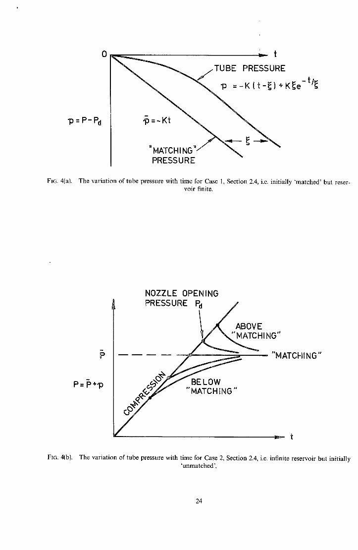
and it can be seen that the tube pressure follows the change in 'matching' pressure/3 (equation (42)) with a delay ¢, as sketched in Fig. 4(a).
Case 2-- inf ini te reservoir, initially 'unmatched' In this case p = O, i.e. P = Pa is constant and written as P. Under these conditions equation (39) reduces to:
whose solution is
dp - p { a~a g ) / ~+ -P~ ,.
aaa
) P = v~a,a - Pa (1 - e-'/¢). (45)
The approximation in equations (34) and (35) demand that p / P << 1 and p / P << 1 and hence from equation (45) that P ----- Pa. The following approximation may therefore be made
ao, p _ p _._ p _ p ~
~-- v(P - 5 ) . (46)
Substituting equation (46) in equation (45) gives,
P = P - Pa = (P - Pa)( 1 - e-t/e) • (47)
The variation of pressure, p, with time given in equation (47) is plotted in Fig. 4(b) for various nozzle opening pressures, Pa, where the pressure during compression is also shown.
10
2.5. Transit T ime Effects
Up to this point the compression process has been considered as taking place instantaneously, the uniform pressure being related to the volume by the adiabatic equation at all times. In practice, however, any change in pressure within the gas comes about due to pressure or rarefaction waves which travel through the gas trans- mitting the information about varying conditions at the ends of the tube. The compression process, for instance, is obtained by a compression wave, generated when the piston initially accelerates, reflecting repeatedly from both ends of the tube causing the pressure within the tube to rise as a 'staircase' in pressure which corresponds to the ramp function in pressure given in Figs. l(b), 2 and 4(b) and equation (9).
A simplified wave diagram demonstrating this process drawn in the x - t plane is shown in Fig. 5. The paths of the waves are given and the pressure resulting from these sketched. The gas velocity at the end of the tube is given by equation (5) and this determines the form of the pressure wave. The piston is first considered to be mass-less. When the nozzle opens, a rarefaction wave is generated which proceeds in a manner similar to the compression previously described. Thus if the tube is 'matched', this rarefaction exactly cancels out the effect of the compression wave such that the net change in pressure from then on is zero. This is not to say that the pressure is constant, but that it rises as much as it falls and it is the object of the following analysis to estimate the magnitude of this disturbance. The 'matching' process as described above is also shown in Fig. 5(a).
The problem as stated is multi-isentropic since the region behind the piston will not be at a constant entropy, the reservoir gas having suffered various entropy increases during its passage into the tube. Thus a solution of such a problem is somewhat complex and an easier case, which probably is also applicable to the physical problem, is solved. If the piston has a finite mass, then it would not follow the instantaneous velocity changes shown in Fig. 5(a) and would be more likely to follow the 'smoothed' velocity shown in Fig. 5(b), i.e. it would not transmit but would reflect the pressure wave. Thus the problem of the smooth piston history as shown in Fig. 5(b) is solved in the region ahead of the piston.
As the problem is now isentropic the velocity change across a 'sharp' pressure wave in Fig. 5(b) is constant thoughout its history, if the possibility of shock formation is ignored. Hence determining the piston velocity enables the gas velocity in the final wave to be found and the pressure amplitude, AP, follows from the acoustic approximation as
AP = ?u__yp (48) P 2,
From the isentropic relationship the piston velocity is given by,
up Y PA 1 dt ] c" (49)
If the reservoir is opened instantaneously to the tube this velocity is a maximum and given by,
_ w_ laPI (50) up r PoA ~ dt ] c
and substituting equation (9) into equation (50) gives,
up _ _I A*~ P - '~ - f l l -~- - ]~- ° . (51)
The resulting amplitude of the pressure wave found by substituting equation (51) into equation (48) would be
_ = [ A * ~ P
The magnitude given by equation (52) overestimates the amplitude of the wave for it assumes that the reservoir valve opens instantaneously and in practice this could be opened slowly in order to eliminate this effect. For example, if the reservoir valve was partially opened such that compression occurred without any appreciable increase in piston velocity and only just prior to the 'matching' pressure being reached was the reservoir valve suddenly opened to give the 'matching' mass flow rate then the piston velocity would be given from equation (49)
11
as,
u , = ~ - ~ ~ - f I ~-d-; i c
which using equation (9) gives,
IA*o~ IPoX 1/~
Substituting equation (53) into equation (48) gives a pressure wave amplitude of
= ~,1~ l p I , (54)
much smaller than that given by equation (52). In practice therefore, by suitable opening of the reservoir valve the compression disturbance may be, to all intents and purposes, eliminated.
The working section nozzle, on the other hand, must be opened instantaneously and using the acoustic approximation the amplitude of the rarefaction wave produced is given by,
AP - ~'a. (55) P
is given by equation (18) and hence,
W = /~y " (56)
Equation (56) predicts therefore a pressure wave amplitude greater than equation (54). An estimate of the amplitude of disturbance due to transit time effects may therefore be found from equation (56). As these waves are reflected from the end wall of the tube there is pressure doubling and hence the resulting disturbance in nozzle stagnation pressure may be estimated as
(A,) AP 2/~y (57) P - -A-
Equation (57) restricts the length of the tube, for if a given volume is required the area of the tube must be such as to keep the pressure disturbance to within permissible limits.
3. Design Equations and Charts
In this section the previous equations are collected in a more convenient form in order to aid in the design of light-piston wind-tunnels.
The design problem may be stated as follows: 'Given a working-section cross-sectional area and a desired working-section Mach number, find the volume of the piston tube required to provide a specified running time'. Having ascertained this dimension the pressure fluctuations resulting from piston oscillations then determine the maximum piston mass allowable and the necessary reservoir requirements are set by the per- missible drop in nozzle plenum pressure during the run.
The sequence of steps necessary are shown in the block diagram in Fig. (6). A characteristic tube time Ztube is used in order to simplify the equations. This time is defined as
W Z~be ~aoA*' (58)
and is recognisable as the time taken to expel the test gas through the nozzle without any compression heating
12
being performed. The actual running time %~, is less than this because of the compression required to heat the gas and from equation (12) is given by
(59)
The 'matching' temperature is obtained from the isentropic relationship,
= ~Po] (60)
and substitution of equation (60) into equation (59) for P/Po gives
[ To/(7+ 1)/2(~- 1~ ~'run = "Etube[-~a ] (61)
The tube volume may be obtained from equation (58) as
W = flA*aort~be. (62)
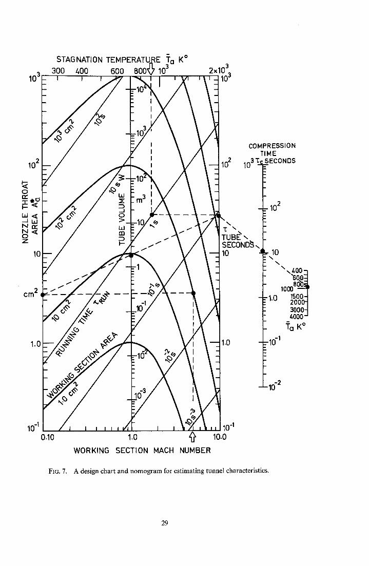
Equations (61) and (62) show how the temperature required and the running time determine the tube volume for a given initial temperature, T 0, which determines a0. These equations are presented in the chart in Fig. (7) for the starting temperature To = 300 degrees K. Also given in this chart is the standard relationship between working section area, Mach number and the throat area such that from the former the throat area may be found and together with the necessary tube time, etuDe, the required tube volume, IV,, may be read from the nomogram. If the starting temperature is not equal to 300 degrees K and is increased to T~, the tube time, equation (61), will decrease as (To/T'o) ~+ 1)/2(-e- 1) and it will be seen from equation (62) that the required volume will decrease by (To/T'o) 1/~-1). A substantial advantage will be obtained if the initial temperature is as high as possible. The ratio of running time to tube time is plotted as a function of the initial temperature in Fig. 8.
The compression time may be derived from equation (9) which may be rewritten in the form
,.ftube ~ Po I (63)
The compression time may then be approximated by
~c ~ P/(dP/dt)c,
i.e.
..ftub¢/po / (?-1)/2~ T T/
Alternatively in terms of the temperature ratio (To~To),
~---"ftube [ To / ~ Zc ? ~Ta] (64)
as plotted in Fig. 7. With the volume of the tube determined from equation (62) the necessary tube cross-sectional area may be
derived from equation (57) which gives an estimate of the pressure disturbances due to wave motion. For 7 = 1.4, equation (57) may be expressed approximately as
--=- -"- 1.6 P
13
and hence for a 5 per cent pressure disturbance, the tube area has to be at least 32 times the nozzle throat area. The length of the tube is therefore determined as the volume is known.
The pressure oscillations due to piston oscillation may now be determined. 'Firstly the period of these may be found from equation (27) which, in conjunction with the isentropic relationship in region (a), may be ex- pressed as
The value of T(~LM/AP) ~ from equation (65) is plotted in Fig. 9. The corresponding pressure oscillation follows from equation (29) and this may be simplified so as to express the results in terms of quantities previously evaluated. In equation (29) u'pd may be expressed, using equation (49), as
which in conjunction with equations (63) and (59) gives
Substitution of equation (66) into equation (29) gives an expression for the pressure fluctuations.
P - 2~Z~b---~LZ~-_j z~-." (67)
The amplitude of the pressure oscillation may thus be found from the values of ~,~n, T and Zt, be. The allowable piston mass may be determined from equations (65) and (67) such that AP is kept within the required limits.
The necessary reservoir size may be found from the analysis already performed in case 1 of Section 2.4, where the change in pressure from 'matching' conditions due to a finite reservoir volume was given by equa- tion (44). As the change in p must be small, equation (44) may be approximated as
Kt 2 P= 23"
Within the running time the pressure drop then becomes
Kz~. P - 23 " (68)
Hence using equations (37), (39), (42), (58) and (59) with equation (68) the following expression is obtained,
P - 4 " " (69)
Equation (69) enables the required reservoir capacity, V,P r, to be determined for a certain tube pressure drop, p, within the running time.
The size of the reservoir throat may be found from equation (37) which gives the ratio * * Ar / Aa as,
A* aa P
This may be written as
AT = 1T~] . ~ . (70)
14
4. Experimental Results
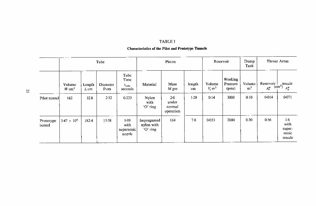
Experiments were conducted in order to test the accuracy of the analysis presented in previous sections. Two light piston wind tunnels have been constructed for this purpose, the first being a small scale pilot model with a tube diameter of 2.52 cm and length 32.8 cm, the second, a prototype version, having a tube diameter of 15.58 cm and length 1.82 m. Photographs and diagrams showing both of these tunnels are shown in Figs. 10 and 11 and they are described below. The dimensions of the tunnels are given in Table 1.
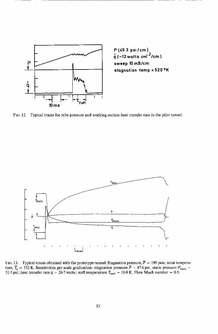
The pilot tunnel was driven from a reservoir consisting of one standard high-pressure gas-cylinder through a hand-operated ball-valve and a throat of diameter 0.12 cm. The nozzle throat was of 0-32 cm diameter and was sealed initially by 'Melinex' diaphragms, the bursting pressures of these diaphragms determining the 'matching' pressures. Pressure transducers were installed so as to read the tube and nozzle pressure and a stagnation point thin-film heat-transfer gauge was placed in the conical supersonic-nozzle. In the experiments the initial tube pressure was always atmospheric and the dump tanks evacuated. The reservoir pressure was adjusted in order to obtain 'matching' conditions and the ball-valve, when operated quickly by hand, was suffi- ciently fast for the purposes of the experiment. A typical result from the pilot tunnel may be seen in Fig. 12 where the tube pressure may be seen rising linearly during compression and remaining constant during the running time. Oscillations in pressure due to piston mass effects may be clearly seen in this figure and it may also be seen that the oscillation frequency increases as the piston nears the end of the tube. This last effect would be predicted by equation (27). The stagnation point heat transfer rate in Fig. 12 rises and remains sensibly constant during the run but falls just prior to the end of the running time.
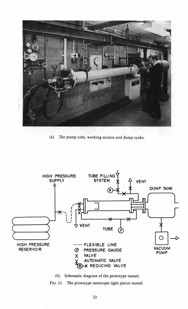
The prototype tunnel was driven from a reservoir comprising five high pressure storage cylinders. The reservoir throat was of diameter 0.85 cm and the nozzle throat area varied from 1.61 to 7.74 cm 2. Melinex diaphragms were again used for opening the nozzle and electro-pneumatic ball-valves with suitable sequencing were used to open the reservoir to the tube and vent the tube after the run. Subsonic and supersonic working- section nozzles were used in this tunnel and pressure transducers were installed in both the pump tube and the working section. Wall heat transfer measurements were made along these nozzles and a stagnation-temperature probe was used in the supersonic nozzle. 'Matching' conditions were obtained by adjusting the reservoir pressure as before; the initial tube pressure could be varied and hence a wide range of nozzle plenum pressures and temperatures were obtainable. A set of typical results from this tunnel may be seen in Fig. 13, and the steady conditions during the run are reflected in the constant static pressure. Nozzle wall surface temperature and inferred heat-transfer rate may be seen in this figure where the decreasing heat-transfer rate is due to the ap- preciable rise in wall temperature. In a similar manner to that observed in the pilot tunnel, the heat-transfer rate falls suddenly, prior to the end of the pressure running time.
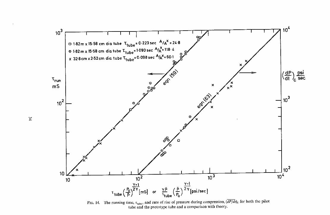
The basic 'matching' equations were tested by comparing the experimental running time with the theoretical value from equation (59) and also by comparing the required rate of rise of tube pressure during compression with that given by equation (63). The results are shown in Fig. 14 where it can be seen that the results for both tunnels compare favourably with the theory. Th e rate of rise of tube pressure during compression has been used for the purpose of comparison rather than any theoretical reservoir mass-flow rate since this quantity is unaf- fected'by losses in the pipe connecting reservoir and tube. From Fig. 14 it may be seen that the theoretical expressions hold true for both tunnels over a range of running times between 10 mS and 1 second.
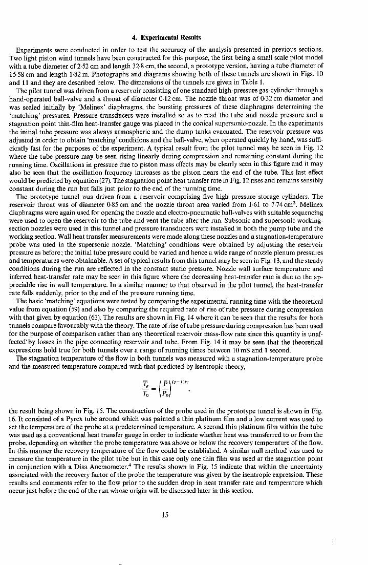
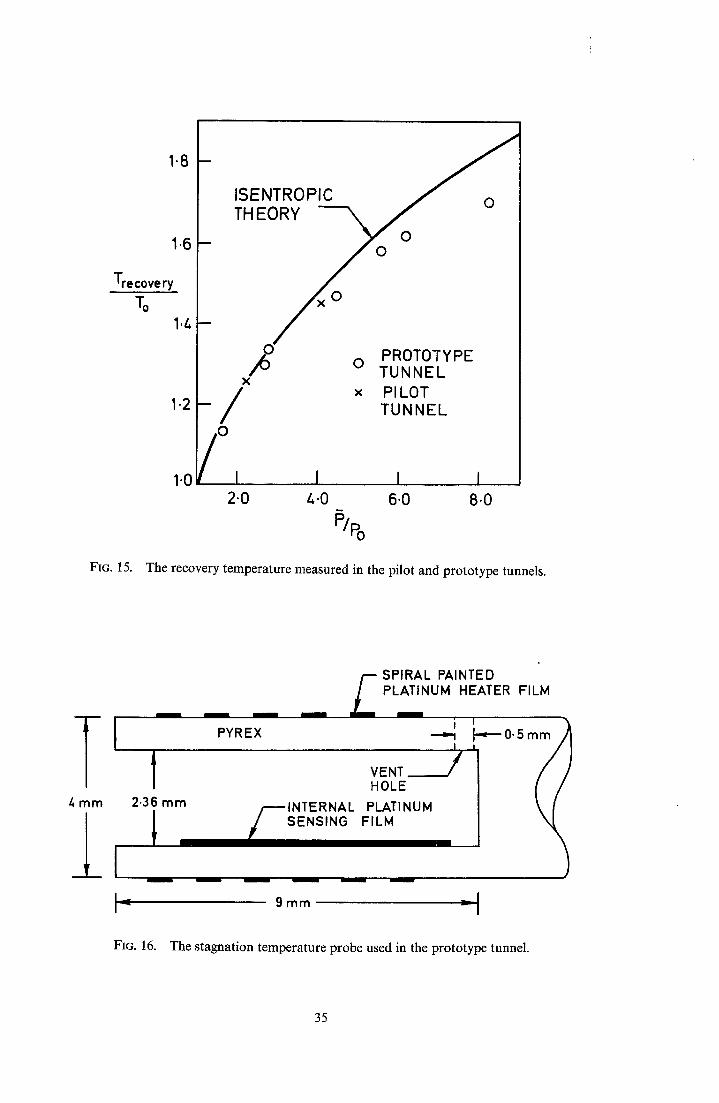
The stagnation temperature of the flow in both tunnels was measured with a stagnation-temperature probe and the measured temperature compared with that predicted by isentropic theory,
Ta [ P__I (~-1)/~ -~oo=IPo] ,
the result being shown in Fig. 15. The construction of the probe used in the prototype tunnel is shown in Fig. 16. It consisted of a Pyrex tube around which was painted a thin platinum film and a low current was used to set the temperature of the probe at a predetermined temperature. A second thin platinum film within the tube was used as a conventional heat transfer gauge in order to indicate whether heat was transferred to or from the probe, depending on whether the probe temperature was above or below the recovery temperature of the flow. In this manner the recovery temperature of the flow could be established. A similar null method was used to measure the temperature in the pilot tube but in this case only one thin film was used at the stagnation point in conjunction with a Disa Anemometer. 4 The results shown in Fig. 15 indicate that within the uncertainty associated with the recovery factor of the probe the temperature was given by the isentropic expression. These results and comments refer to the flow prior to the sudden drop in heat transfer rate and temperature which occur just before the end of the run whose origin will be discussed later in this section.
15
The theory deduced for piston oscillations, Section 2.3, was tested in the pilot tunnel, since the prototype was designed to minimise effects arising from this phenomenon. The period and amplitude of the oscillation for a given compression ratio as a function of the piston mass is plotted in Fig. 17. The experimental results for ~ compare well with equation (65) but those for AP are above that predicted by equation (67) for high piston masses. The explanation for this discrepancy is that at the high piston-masses the piston was still oscillat- ing from the opening of the reservoir ball-valve when the nozzle opened and pressure fluctuations larger than predicted by equation (67) resulted. For a small piston-mass the variation of z and AP with compression ratio is given in Fig. 18, where good agreement with equations (65) and (67) is shown.
The equations derived for the off-design performance of the tunnel in Section 2.4 were verified using the large piston tunnel by deliberately using nozzle diaphragms which burst at pressures above and below the 'matching' condition. Typical results showing the tube pressure as a function of time are given in Fig. 19(a) where it can be seen that the relaxation to the 'matching' pressure is not accomplished within the running time. The initial slope of the pressure trace was compared with that predicted by the special case in Section 2.4 which applies to this situation. Equation (47) gives the initial slope as,
dP P - P , t P - P a
dt -- ~ -- W/(flyVA,aaaa ) (71)
and this expression is plotted in Fig. 19(b) where good agreement with the experiment is again found. The premature termination of the running time in the light piston tunnel posed an interesting problem.
It was recognised at an early stage from the results in the pilot tunnel that a vortex within the tube was being expelled from the tube at the end of the running time. 1 It was uncertain however whether this vortex was situa- ted at the entrance to the nozzle (vortex A in Fig. 20) or whether it was associated with the piston which was sweeping up the tube boundary layer ahead of it (vortex B in Fig. 20). An experiment was therefore conducted to determine which vortex was responsible for this effect. The prototype piston tunnel was run under identical conditions for several runs, the piston being initially at different positions down the tube, hence giving dif- ferent running times. If the vortex A was responsible for the effect, it would be expected that the running time would be curtailed by a constant amount, whereas if vortex B was responsible, the loss of running time should increase with the initial length of tube ahead of the piston. The result of the experiment shown in Fig. 21 shows clearly that the vortex B due to rolled-up boundary layer is responsible for the loss in running time. The cold gas in this vortex is detrimental to the operation of the tunnel ; whereas any boundary layer gas originating at the start of the compression which forms a vortex will not be cold for it will have undergone compression heating. In order to estimate the effect of the 'cold' vortex, it was assumed that it starts its formation at the beginning of the running time when the nozzle diaphragm opens and the piston which has been reduced to a low velocity suddenly accelerates to its 'matching' velocity. Such a situation has been examined by Tabaczynski, Hoult and Keck s who measured the size of the piston vortex for a step function in piston velocity. For stroke Reynolds number greater than 2 x 10⁴ the vortex was turbulent and the cross-sectional area of the vortex, A v, was related to the stroke, X, by the expression,
At~ X z - 0.008
which, in terms of the diameter of the vortex, is
Dv ~ - = 0.10. (72)
In the experimehts conducted in the two tunnels the stroke Reynolds number, Re~, was in most cases greater than 2 x 10⁴ based on the compressed length and the 'matching' velocity where
Rex = p a b l p X a d / f f t a .
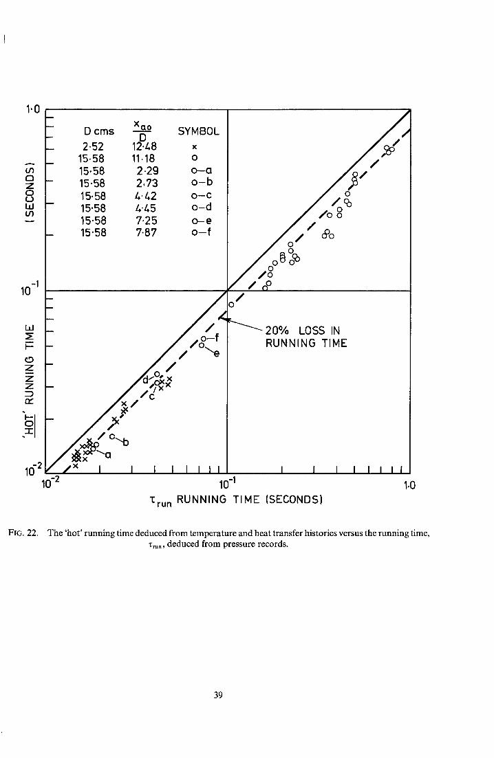
If it is assumed that cold gas enters the nozzle when the vortex first reaches the nozzle (i.e. when the piston is a distance D v from the nozzle) it follows from equation (72) that the running time should be curtailed by a constant fraction of the running time. The results for 'hot' running time were therefore plotted versus the 'pres- sure' running time in Fig. 22 and for all the conditions used in both tunnels it does indeed appear that there is approximately a constant fractional loss in running time. The observed loss is approximately 20 per cent compared with I0 per cent predicted by equation (72). It would appear fortunate that this loss occurs at the end of the running time and does not affect the extremely constant conditions in the majority of the run.
16
5. Conclusion
An important advantage of the intermittent wind-tunnel is that transient techniques may be used for mea- suring heat transfer and the prototype Isentropic Light Piston Tunnel has for some time been used routinely for this purpose. An example of this measurement is shown in Fig. 23 where the heat transfer rate along the wall of the supersonic nozzle is shown in its usual non-dimensional form and also compared with theoretical predictions. Another tunnel, slightly longer than the prototype, has been operated with a subsonic working section where the Mach number was determined by the back pressure within the dump tank. The nozzle was opened with an explosive driven shutter when the required ratio of tube to dump tank pressure had been reached during compression. The "matching" criterion, as defined by equation (7), worked well under these conditions where A* is the effective throat area. It is also possible that the reservoir throat could be subsonic and this situation is also covered by equation (7), the mass flow rate rhr corresponding to these subsonic conditions being taken in order to establish "matching". In this case, however, the reservoir requirements would be severe and if an analysis similar to that in Section 2.4 is carried out for the subsonic case the reservoir requirement equation (69) becomes, in the incompressible limit,
P = 7 ~ ( 2 7 - l P - - + - P - - - - ) = "
Thus it would be preferable to have a sonic reservoir throat. Reservoir requirements would be completely relaxed however if the reservoir throat could be automatically controlled so as to maintain the "matching" mass flow rate.
The Isentropic Light Piston Tunnel provides a good source for gas at modest temperature for running times of the order ~ of seconds. Its theory of operation is dependent on the gas within it being in equilibrium, i.e. the sound transit time is small compared to the running time. The main innovation is the use of the 'matching' process to ensure steady conditions during the running time and this principle has been verified by the experi- ments described in this report.
17
a
A
A*
A*
A*
Av
Cv
D
Dv
K
L
m
rh
M
P
P,
P
AP
0 R
t
T
U
V
Ag
W
X
X
tl
LIST O F SYMBOLS velocity of sound
tube cross-sectional area
throat area
nozzle throat area
reservoir throat area
vortex cross-sectional area
specific heat at constant volume
tube diameter
vortex diameter
yflA*ardP/V r constant in equation (42)
tube length
mass of gas
mass flow rate
piston mass
P - Pn in equation (35)
Pr - Prn in equation (34)
P - Pa in equation (38)
pressure
pressure difference or change, amplitude of pressure oscillation
rate of rise of pressure during compression
heat transfer rate per unit area
Gas Constant per unit mass
time
temperature
velocity
b/p - -
volume
volume leaving reservoir
volumetric flow rate
tube volume
distance along tube from nozzle
piston stroke
2 / O , + 1,/[2(~,- 1,] y + 1] = 0.578 for 7 = 1.4
ratio of specific heats
W/(BTvA*aa,O in equation (39)
v~
18
P
"~'rurt
~tube
~C
T
#
Suffices
0
a
b
d
r
P
B
3y - 1 . . . . . . m equation (34) 2r
density
running time
tube time = W/~aoA* equation (58)
compression time
period of piston oscillation
viscosity
initial conditions
value in region ahead of the piston (Fig. l(a))
value in region behind the piston (Fig. l(a))
value at the time the nozzle diaphragm bursts or valve opens
value in the reservoir
piston
'matching' value of B
19
No. Author(s)
1 T.V. Jones and D. L. Schultz
2 B, E. Richards and K. R. Enkenhus
3 O. Leuchter . . . . . . . .
4 J. E. La Graaff, J. P. Batham F, K, Owen
5 R.J. Tabaczynski, D. P. Hoult and J. C. Keck
6 W.M. Kays . . . . . . . .
7 L.F. Crabtree, R, L. Dommett and J. G. Woodley
REFERENCES
Title, etc.
A study of film cooling related to gas turbines using transient techniques.
A.R.C, 32 420 (1970).
Hypersonic testing in the VKI Longshot free-piston tunnel. A.I.A.A.J,, 8, 6, pp. 1020-1025,
Soufflerie Pilote Hypersonique R ~. O.N,E.R.A, T.P. No. 296 (1965).
An interim report on a new method for the determination of total temperature in Gun Tunnels,
A,R.C. 31 246 (1969).
High Reynolds number flow in a moving corner. J. Fluid Mech., vol. 42, pt. 2, p. 249. (1970).
Convective Heat and Mass Transfer, McGraw-Hill (1966).
Estimation of heat transfer to flat plates, cones and blunt bodies. A.R,C. R. & M. 3637 (1965),
20
- !
TABLE 1
Characteristics of the Pilot and Prototype Tunnels
tO
Pilot tunnel
Prototype tunnel
Volume Wcm 3
162
3.47 x 10⁴
Length L cm
32.8
182.4
Tube
Diameter D cm
2.52
15.58
Tube Time
~'tube seconds
0.223
1.09 with
supersonic nozzle
Material
Nylon with
'O' ring
Impregnated nylon with
"O" ring
Piston
Mass M gm
2.0 under
normal operation
164
length cm
1-29
7.8
Reservoir
Working Volume Pressure
V~ m 3 (psia)
0.14 3000
0.033 2000
Dump Tank
Volume m 3
0.10
0-30
Throat Areas
Reservoir 2 nozzle A~* ( cm) A*
0.014 0-071
0.56 1-6 with
super- sonic nozzle
RESERVOIR NOZZLE THROAT \ DIAPHRAGMoR VALVE
RESERVOIR \ PISTON~ ~ WORKING II~I~~~ VALVE ~..~ ~ SECTION
MOTION
HIGH PRESSURE PUMP TUBE DUMP RESERVOIR NOZZLE TAN K
FIG. l(a). Schematic diagram of the isentropic light piston tunnel.
PRESSURE
RUNNING TIME
, MATCHED TUBE / - ~ PRESS~.E / "~ BELOW
MATCHI NG
.~'COMPRESSION WORKING SECTION STATIC PRESSURE
FIG. l(b). Ideal form of the tube and working section pressure histories.
22
~...., / %.,,. j / MATCHING
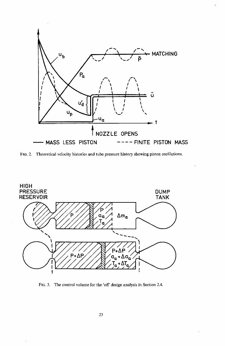
FIG. 2.
Up
/ t " \ f "
I l t l
! I I l I l I l
~ t
I NOZZLE OPENS MASS LESS PISTON FINITE PISTON MASS
Theoretical velocity histories and tube pressure history showing piston oscillations.
HIGH PRESSURE RESERVOIR
\
Z~ma
JU//7 *. ~ V / / ~ o o • A oo, T.,AT
DUMP TANK
FIG. 3. The control volume for the 'off' design analysis in Section 2.4.
23
0
I =P-Pd
~ ~ ~ " ~ ~ / , . TU B E P RES---S UtRE
PRESSURE FIG. 4(a). The variation of tube pressure with time for Case 1, Section 2.4, i.e. initially 'matched' but reser-
voir finite.
NOZZLE OPENING PRESSURE Pd
I /.ABOVE
~- - - t
FIG. 4(b). The variation of tube pressure with time for Case 2, Section 2.4, i.e. infinite reservoir but initially 'unmatched'.
24
I X
RESERVOIR C~ -I
PISTON MOTION I AVERAGE ,,/.PRESSURE
I
-.---NOZZLE OPE
~ NOZZLE
FIG. 5(a). x -- t diagram of the wave motion associated with the compression and 'matching' condition for a piston with negligible mass.
FIo. 5(b).
X
AVERAGE
OPENS/
/ , /
x - t diagram for a smooth piston history where the waves are completely reflected by the piston.
25
TUBE
WORKING SECTION
AREA ~
MACH V ' N U M B E F ~
WAV E F LUCTUATIO NS
PISTO N MASS
STAGNATION CONDITION
%
AQ "I;TUBE
\s2 62 { " ~ "(;RUN
\
L \ \ \ \
~Y L U °'MENs'°"s \J P /
OSCILLATION i Ap PRESSURE I FLUCTUATION t
't I I I I I L !
RESERVOIR
ALLOWED PRESSURE DROP
,p
P RESERVOIR CAPACITY
FIGURES REFER TO EQUATION NUMBERS.
FIG. 6. A block diagram showing a convenient method of determining the tunnel characteristics.
26
FIG. 7.
A Design Chart and Nomogram
Entering the chart with the desired working section Mach number the nozzle throat area, A*, may be found for a given working section area. Entering with the desired stagnation temperature, Ta, the tube time, Ztube, necessary for a given running time, Zrun, may be read. A line joining the values of A* and Zt~be enables the tube volume, W~ to be found from the intercept of this line with the central scale. The compression time, Zc, may be estimated from the nomogram on the right hand side where a line joining Ztube and T, gives the compression time as the intercept on the Zc scale.
28
10 3
STAG NATI O N 300 400
TEMPERATU..LRE ~a 600 800J~ 103
K ° 2x10 3_ T---110 :~
10 2
o
i_ . ;< lad
N
o z
10
cm 2
1.Oh--
f
f I
~E D
o > J,i m D
f
f I
__11o
T " TUBI~" \ SECOND~ x
10 a
- - t l . 0 -
COMPRESSION TIME
10 3 "~ SECONDS
10 2 _
, lO \
---1.0
_10 -I
_10 .2
\,,,~00 Z] "6o.od
1 0 0 0 8 ~
3ooo-I 4000 -~
?a. K °
10 -1
0.10 1.o
WORKING SECTION MACH NUMBER
j..J 10 "1 10.0
FIG. 7. A design chart and nomogram for estimating tunnel characteristics.
29
FIG. 8.
1.0
Xru. 10 -1 Ttube
-2 10
300 t.00 600 800 1000 1500 2000 T. (OK)
The effect of the initial temperature, T o, on the running time zmn from equation (61).
FIG. 9.
T
27)
2.0
1.0
0 0
D I t I
I I I I 10 20
(P/Po)
The variation of period of piston oscillation, T, with compression ratio, P/Po, from equation (65).
30
t
(a). Isentropic light piston pilot tunnel test rig.
HEAT
i FDIAPHRAGMj /-TUBE / .
I jq~"' -~ E/1FT /.'2 o /
I. .%~ HIGH PRESSURE . ~ / SUPPLY BOTTLE
(b). Schematic diagram of the pilot tunnel.
FIG. 10. The pilot iscntropic light piston tunnel.
TOP-UP SUPPLY
31
(a). The pump tube, working section and dump tanks.
I
,.L. HIGH PRESSURE TUBE FILLINGS'
t ..N(
HIGH PRESSURE . . . . FLEXIBLE LINE RESERVOIR (Z) PRESSURE GAUGE
X VALVE UTO MAT IC VALVE
REDUCING VALVE
VENT
DUMP TANK
l_ f
VACUUM PUMP
(b). Schematic diagram of the prototype tunnel.
FIG. 11. The prototype isentropic light piston tunnel.
Typical traces for tube pressure and working section heat transfer rate in the pilot tunnel.
PSTATIC
WALL
4
J
~,~.. PSTATIC
I I I I I I t I I I I I I I I I
FIG. 13. Typical traces obtained with the prototype tunnel. Stagnation pressure, P = 190 psia; total tempera- ture, Ta = 552 K. Sensitivities per scale graduation : stagnation pressure P - 47.6 psi; static pressure P s t a t i e - -
51.3 psi; heat transfer rate t~ - 26.7 watts; wall temperature Twall -- 16.9 K. Flow Mach number = 0-5.
33
10 3
~run mS
10 2
10
m
- /
- / x x
,/x
_/, S . x I I I I I 10 10 2
Y÷I
O 1.82m x 15.58 cm dia tube "Ctube = 0.223 sec A/AX : 2/,.8 / o
O 1.82mx15"58cm diatube'Ctu h :l.090sec A/~ :118"4 J ___e x ® O
x 32-8cm x2.52cm dia tube 1:tube =0"098sec A//~ = 6 0 . ~ '
®
2I
FIG. 14.
X
X
X yx ®
X
X X
I I I I I I i 10 3
C Po~2Y [mS] or Y-~ (~00) 2Y [psi/sec] 1: tube \--p'/ "{tube
The running time, Zt~be, and rate of rise of pressure during compression, (dP/dt)c for both the pilot tube and the prototype tube and a comparison with theory.
10 ~
sec
103
10 2
10 ~
1.8
1"6
Trecovery
To I.~--
1 . 2 -
x
/ 0
1.0/ I 2"0
ISENTROPIC ~ ~ o THEORY ~
~ O/xO c~ PROTOTYPE
/v v TUNNEL x PI LOT
TUNNEL
I I I 4-0 6.0 8-0 m
P/Po FIG. 15. The recovery temperature measured in the pilot and prototype tunnels.
T I /, mm 2"36 rnm
It I FIG. 16.
-SPIRAL PAINTED PLATINUM HEATER FILM
PYREX i
I
INTERNAL SENSING
VENT / HOLE PLATINUM
FILM
L"'-0"5mm 1
( 9ram ~---I
The stagnation temperature probe used in the prototype tunnel.
35
FIG. 17.
10
,I. mS
5
J 0 = 61.5 psia ~ /
_ ~ = 1 aim eo,~i, /x_ o / /
V , / / , / -
/ .
~~ - I I -0 0 1 2 3 /~ gms 1/2
8
6
psta
The period T, and amplitude, AP, of the pressure fluctuations due to piston oscillations as a functiol of piston mass and a comparison with theory.
FIG. 18.
8
6 ?
mS
8
AP ps,a
\ ® M = 2.0 gins .~N
0 0 50 100 150 200
psia
The period, T, and amplitude, AP, of the pressure fluctuations due to piston oscillations as a function of the matching pressure for-a fixed piston mass and a comparison with theory.
36
BELOW MATCHING MATCHING
F /dP ~
;/lo, j I ° ,
ABOVE MATCHING
dP dt
FIG. 19(a). Typical records of tube pressure for 'off matching' conditions.
100
50
dP d'T" 0
psi sec -50
-100
-150
~~Qo Pd psia I I i i
o 150 50 100 ~1 ° 200
eqn (71)
psi Po =34.7 o
FIG. 19(b). A comparison of the experimental and theoretical slope of tube pressure, dP/dt, for 'off matching' conditions.
37
FiG. 20.
f •
j
P I S T O N / ' , -, f J f j
/ j
NOZZLE
Possible vortex formations within the tube. Vortex A will be constant whereas vortex B will grow with piston movement.
20
~loss mS
10
0
0
-- 0 0
I 0 1.0 2.0
xQo METRES
FiG. 21. Loss in 'hot ' running time, z~ .... as a function of initial position of the piston, xa0. This demonstrates that vortex B is responsible for this loss and not vortex A in Fig. 20.
38
1.0
O3 r-~ Z O ¢.1 LIJ O3
-1 10
m
m
m
m
m
m
Ld _>: I--
0 z Z Z 23 re"
_s I 10 .2
10 -2
D cms xa° SYMBOL D
2.52 12.z,8 x 15.58 11.18 o 15.58 2.29 o - a 15.58 2,73 o - b 15.58 /~.42 o-c
15.58 /-,-45 o -d 15.58 7.25 o - e 15.58 7-87 o - f
- / z
! i / ' / / - \ e - I . , ' r×^ _ ~ f ' C
/x~ / °'~b / ~O..o / / x I I I I I i ~i
10 -!
S,' o //o °
f / n o /
o
20% LOSS IN RUNNING TIME
I I I I I I I I
1.0 1:ru n RUNNING TIME (SECONDS)
FIG. 22. The 'hot' running time deduced from temperature and heat transfer histories versus the running time, x~,, deduced from pressure records.
FIG. 23. Stanton number versus Reynolds number for the supersonic nozzle from wall heat transfer mea- surements and a comparison with fiat plate theory from Ref. (6) Kays and Ref. (7) Crabtree et al.
Printed in England for Her Majesty's Stationery Office by J. W. Arrowsmith Ltd., Bristol BS3 2NT Dd. 505715 K5 10/73