3 66 On the Flow of Waterthrough Pipes and Passages havi Converging or Diverging Boundaries. By Prof. A. H. G ibson, D.Sc ., University College, Dundee. (Communicated by Prof. J. E. Petavel, F.R.S. Received December 10, 1909, _ Read February 10, 1910.) CONTENTS. PAGE 1. Introduction ................. 366 2. Description of Apparatus—Method of correcting Results for Friction... 368 3. Loss of Head in a Circular Pipe with Diverging Boundaries.................. 370 4. Loss of Head in Pipes of Square Section with Diverging Boundaries ... 374 5. Loss of Head in a Pipe of Rectangular Section with Diverging Boundaries................................................................................................. 375 6. Loss of Head in a Circular Tube with Converging Boundaries : Critical Velocity ..................................................................................................... 376 7. Summary and Conclusions.............................................................................. 377 1. Introduction.—As is well known, diverging boundaries in a passage conveying a fluid tend to unsteadiness of flow with consequent loss of head in eddy formation, the energy loss in such a pipe being greater than in a parallel pipe with the same mean velocity of flow. Converging boundaries, on the other hand, have an opposite tendency, and the present investigation, which was commenced in the engineering laboratories of the Manchester University, and has been completed in the engineering department of University College, Dundee, was undertaken with a view of determining: (1) how this loss depends upon the angle of divergence of opposite sides of a circular pipe with uniformly diverging boundaries; (2) the relative values of the losses in a circular and a square pipe having the same angle of divergence, or increasing in area between the same initial and final limits, in the same length; (3) the effect of a divergence in the one pair of sides of a rectangular pipe, the second pair being parallel; (4) the effect of a variable, as opposed to a regular, rate of divergence of the sides; (5) the loss of head and, if possible, the critical velocity in a circular pipe with uniformly converging boundaries. Twenty-five pipes in all were constructed for use in the experiments. These were very carefully made of wood, finished off with a coating of shellac varnish. They may be divided into three sets. A. Circular Pipes having a Straight Taper.—These had a uniform smaller diameter of 1*5 inches and a larger diameter of 3 inches. Calling 6 the angle included by opposite generating lines of the cone of which the pipe forms a on May 14, 2018 http://rspa.royalsocietypublishing.org/ Downloaded from
Transcript
3 66
On the Flow o f Water through Pipes and Passages having Converging or Diverging Boundaries.
By Prof. A. H. G ibson , D.Sc., University College, Dundee.
(Communicated by Prof. J. E. Petavel, F.R.S. Received December 10, 1909,_Read February 10, 1910.)
CONTENTS.PAGE
1. Introduction................. 3662. Description of Apparatus—Method of correcting Results for Friction... 3683. Loss of Head in a Circular Pipe with Diverging Boundaries.................. 3704. Loss of Head in Pipes of Square Section with Diverging Boundaries ... 3745. Loss of Head in a Pipe of Rectangular Section with Diverging
Boundaries................................................................................................. 3756. Loss of Head in a Circular Tube with Converging Boundaries : Critical
Velocity..................................................................................................... 3767. Summary and Conclusions.............................................................................. 377
1. Introduction.—As is well known, diverging boundaries in a passage conveying a fluid tend to unsteadiness of flow with consequent loss of head in eddy formation, the energy loss in such a pipe being greater than in a parallel pipe with the same mean velocity of flow. Converging boundaries, on the other hand, have an opposite tendency, and the present investigation, which was commenced in the engineering laboratories of the Manchester University, and has been completed in the engineering department of University College, Dundee, was undertaken with a view of determining: (1) how this loss depends upon the angle of divergence of opposite sides of a circular pipe with uniformly diverging boundaries; (2) the relative values of the losses in a circular and a square pipe having the same angle of divergence, or increasing in area between the same initial and final limits, in the same length; (3) the effect of a divergence in the one pair of sides of a rectangular pipe, the second pair being parallel; (4) the effect of a variable, as opposed to a regular, rate of divergence of the sides; (5) the loss of head and, if possible, the critical velocity in a circular pipe with uniformly converging boundaries.
Twenty-five pipes in all were constructed for use in the experiments. These were very carefully made of wood, finished off with a coating of shellac varnish. They may be divided into three sets.
A. Circular Pipes having a Straight Taper.—These had a uniform smaller diameter of 1*5 inches and a larger diameter of 3 inches. Calling 6 the angle included by opposite generating lines of the cone of which the pipe forms a
on May 14, 2018http://rspa.royalsocietypublishing.org/Downloaded from
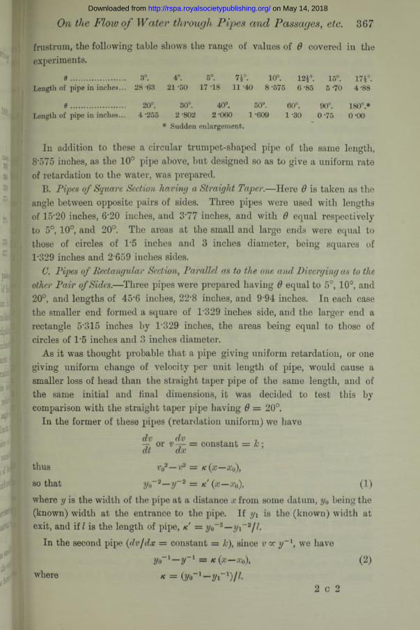
9 ............................. 20°. 30°. 40°. 50°. 60°. 90°. 180°.*Length of pipe in inches... 4*255 2*802 2*060 1*609 1*30 0*75 0*00
* Sudden enlargement.
:® HIsji i |
b I
P 13
of i fIffi. :
.1 \
niii-J.1i t e
In addition to these a circular trumpet-shaped pipe of the same length, 8‘575 inches, as the 10° pipe above, but designed so as to give a uniform rate of retardation to the water, was prepared.
B. Pipes of Square Section having a Straight Taper.—Here 6 is taken as the angle between opposite pairs of sides. Three pipes were used with lengths of 15'20 inches, 6*20 inches, and 3*77 inches, and with 6 equal respectively to 5°, 10°, and 20°. The areas at the small and large ends were equal to those of circles of 1*5 inches and 3 inches diameter, being squares of T329 inches and 2*659 inches sides.
G. Pipes of Rectangular Section, Parallel as to the one and Diverging as to the other Pair of Sides.—Three pipes were prepared having 6 equal to 5°, 10°, and 20°, and lengths of 45’6 inches, 22*8 inches, and 9*94 inches. In each case the smaller end formed a square of 1*329 inches side, and the larger end a rectangle 5*315 inches by 1*329 inches, the areas being equal to those of circles of 1*5 inches and 3 inches diameter.
As it was thought probable that a pipe giving uniform retardation, or one giving uniform change of velocity per unit length of pipe, would cause a smaller loss of head than the straight taper pipe of the same length, and of the same initial and final dimensions, it was decided to test this by comparison with the straight taper pipe having 6 = 20°.
In the former of these pipes (retardation uniform) we haveddvnr* 01—— UI V —
dt dxthus v f —v2so that 11(M1&
i
Jc;
K ( X—
k! (x— Xq), (1)vYiicic y ib uue wiu.i/11 u i une p ip e au & uibuctnue t4/ i i u i i i b u m e uciuuiii, y o u e m y i/iie
(known) width at the entrance to the pipe. If yi is the (known) width at.. .
2/o 3 - 2 / iexit, and if l is the length of pipe, k In the second pipe (dv/dx = constant = k), since cc we have
2/o_ 1 — 2/_1 = k (x —
K — (2/o-1—2/i-1)/7
(2)where
2 c 2
on May 14, 2018http://rspa.royalsocietypublishing.org/Downloaded from
These two pipes were then constructed with boundary curves calculated from equations (1) and (2), one pair of sides being parallel and distant 1-329 inches apart.
In addition to these, one pipe was constructed of rectangular section, converging uniformly as to one pair of sides and diverging uniformly as to the other pair, the initial section being a square of 2-659-inches side, and the final section a rectangle having sides 1-329 inches by 5-315 inches. The sectional area was approximately constant throughout, the object being to determine to what extent such a change in the form, as opposed to the area of the section, affects the loss of head. The length of this pipe was9'94 inches, 6 for the diverging sides being 7° 37' and for the convergingsides 3° 50'.
2. Description of Apparatus.—The apparatus made for the experiments is shown in fig. 1. Here a is the experimental pipe, fitted into brassbushes b and c.These bushes are of the exact shape (circular, square,or rectangular) ofj the pipes, and were finished very carefully to the required dimensions. They are fitted into bored holes in the castings eld, which are machined to fit guides on the cast-iron bed plate The castings are provided with side lugs f f and adjusting screws g, so that the distance between the bushes may be adjusted to suit a pipe of any required length.
I f
F ig. 1.
Each end of the apparatus is fitted with a 2-inch pipe and valve, and either end can be coupled to the supply main, or may be arranged to discharge into the calibrated measuring tank in which all measurements of the discharge were made. Pressure differences were measured at low velocities by means of a differential water-gauge capable of being read to 0-0010 of a foot, and at high velocities by means of a differential mercury gauge. The gauges were coupled to h2 and hA with flow from b to c, and to
on May 14, 2018http://rspa.royalsocietypublishing.org/Downloaded from
and h3 with flow taking place from c to b. The orifices actually piercing the walls of the bushes were not more than 0-025 inch in diameter, and great care was taken that no burr should be left on the interior surface of the bush after drilling these holes.
In the square pipes the pressures were measured at two points in a cross- section ; in one corner, and in the middle of one face. The pressures at the two points were sensibly the same throughout. Where any slight difference was noticed, as was the case in the pipe having the largest angle of divergence, the pressure was rather greater in the corner, and the true pressure has been taken as the arithmetic mean of the two.
In the rectangular pipe the pressure was measured at three points in a cross-section, viz., at the centre of each face and in one corner. Generally speaking, whenever any difference between these pressures was noticed, that in the centre of the shorter face was highest, and that in the centre of the longer face, i.e. of the parallel sides, was lowest. This difference was small, however, in every case (generally less than 0'02 feet), and where it did exist the true pressure has been taken as the arithmetic mean of the greatest and least of these.
After the first few experiments with diverging flow it was found that, owing to the equalising of velocities in a cross-section, there was a gradual rise in the boundary pressure in the larger bush in the direction of flow, further experiments showing that this rise in pressure extended over a distance of as much as 12 inches in the case of the circular pipe having a sudden enlargement of section. For this reason a much longer bush was prepared for the discharge end of the pipe and a series of pressure openings were made, the pressure being taken at a sufficient distance from the end of the conical pipe to ensure of this action being completed. This distance varied from 7 to 13 inches, being greater with the greater angles of divergence. The frictional loss per unit length of each bush was measured for a series of velocities of flow covering the whole range, and from curves plotted from these results the friction losses due to those portions of the bush between the ends of the experimental pipe and the pressure openings have been determined for each experiment, and have been taken into account in determining the effective difference of pressure at the two ends of the pipe. In some cases the pressure was also measured at a point hc, midway along the pipe.
Friction Loss in Conical Pipes.—The friction loss in the conical pipe, as distinct from the loss essentially due to the divergence of its boundaries, may be determined on the assumption that it varies, as the same (wth) power of the velocity as in a parallel pipe having a physically similar inner surface,-
on May 14, 2018http://rspa.royalsocietypublishing.org/Downloaded from
370 Prof. A. H . Gibson. On the FIovj oj [Dec. 10,
Thus, taking the loss of head in a parallel pipe of length “ l ” and diameter “ <1, ” to he given by f lv njdx feet of water, and assuming that the friction loss in a small length hi of a similar, but taper pipe, is given by fv Hhl/dx, we get, for the same friction loss in a parallel pipe as in the taper pipe,
Y*D
where D is the diameter of the equivalent parallel pipe, and where Y is the velocity of flow when passing the same quantity of water as the taper pipe.
In the pipes under consideration, preliminary experiment showed n — 1*78; x = 1*20 ; so that for equal frictional losses, writing v oc d~z, we have
/v 2'38 = |V 38sz.
On plotting (velocities) 2‘38 corresponding to a given flow in the taper pipe, on a base of pipe lengths, the mean height of the diagram gives V2‘38, from which Y and so the diameter of the equivalent parallel pipe, giving the same friction loss as a taper pipe of the same length, can be determined. In this case the pipe equivalent to the circular conical pipes is 2-00 inches diameter, and such a pipe, 26 inches long, was prepared. A series of experiments was carried out to determine the friction loss in this pipe for different flows, and from the curve showing these results the friction losses in the various taper pipes have been determined.
3. Loss of Head■ in Circular Pipes with uniformly Diverging Boundaries.— Calling V\ the mean velocity and the mean pressure in the smaller, and and p2 those in the larger pipe, it may be readily shown that, neglecting the effect of the differences of velocity at different points in the cross-section of the stream, in the case of a sudden enlargement of section if the pressure over the plane surface forming the junction of the pipes is the same as that in the smaller pipe (an assumption which appears to be fairly well justified by
experiment), the loss of head,” + ^ - — ^ is theoretically equal to ^
As this expression depends only on the initial and final areas of the pipes, it has been thought advisable to express the loss of head in the taper pipes in each case as a percentage of this quantity.
On plotting the results of the whole series of experiments on circular pipes, it appears that for values of v, greater than about 5 feet per second and up to about 23 feet per second (the highest velocity attained in the experiments), the percentage loss of head does not vary in any regular manner with the velocity, and appears to be sensibly constant. Below about 5 feet per second the percentage loss falls off somewhat rapidly with decreasing
on May 14, 2018http://rspa.royalsocietypublishing.org/Downloaded from
velocities, though the results show very great irregularities.^The means of all observations above 5 feet per second have been plotted in|fig. 2 on a base
2om
Jo*
on May 14, 2018http://rspa.royalsocietypublishing.org/Downloaded from
of values of 6. From the curve it appears that in these pipes the total loss including friction, attains a minimum value of 13’5 per cent, with a value of 6 about 5° 30'; increases very rapidly with to a maximum of 121 per cent, with an angle of about 63°, afterwards diminishing to 101*7 per cent, with an angle of 180°, i.e. with a sudden change of section.
The mean results obtained on deducting the friction loss in the pipe are plotted and are shown by the dotted curve in fig. 2, and indicate that the loss essentially due to the change of section gradually increases from zero in a parallel pipe; as before, attains a maximum of about 120 per cent, with an angle of 63°; and afterwards diminishes to 101*7 per cent, as 0 is increased up to 180°.
The following is suggested as a possible explanation of this phenomenon. In the case of a sudden enlargement of section, the high-velocity water at “ a,” fig. 3, impinging on the surrounding annulus of dead water, carries
a certain proportion forward
F ig. 3.
in virtue of its viscosity, this water being replaced by a backward eddy flow from regions of higher pressure further along the pipe. The more readily this backward flow can take place and the less the resistance to the removal of the annulus, the less
the difference in the velocities of adjacent layers of the fluid, and, in consequence, the less the loss of energy in impact. Where, owing to the cutting off of the corner at “ b,” the free backward eddy formation is restricted, this will have the effect of increasing the resistance to the removal of the annulus immediately surrounding the entering stream, and consequently of increasing the impact loss. The critical value of 6, at which this increased loss becomes exactly balanced by the reduced loss due to the more gradual divergence of the stream in succeeding portions of the tube, is apparently about 63°. The restriction of the backward flow to the face at “ b will be accompanied by a reduction of pressure over this face, and this effect is well marked in the experiments. Calling pc the pressure at the centre of the length of the diverging portion of the tube, p\ and p 2 the pressures at entrance and exit, the following table indicates how p c varies with the angle of divergence :—
e ....Pc-Pi;P’3—Pi
15°.
o-n30°.
0*38
40°.
0-0060°.
-0 * 6 2
90°.
- 0-22
180°.
- 0*11
on May 14, 2018http://rspa.royalsocietypublishing.org/Downloaded from
From 40° to 180° the pressure over the diverging faces is less than that in either the small or large parallel pipes, while this pressure has its least value for a given velocity and a given pressure in the small pipe when is about 63°. Values of 0 equal to 41° and 180° have approximately the same value for^>c, so that theoretically the losses in such tubes should be equal. From the curves of fig. 2 it appears that this is the case, the losses being respectively 103 per cent, when 0 = 41° and 1017 per cent, when 6 = 180°.
I t is a suggestive fact that the semi-angle of divergence (31° 30') of the tube giving the maximum loss is, practically, identical with that angle of obliquity of a square inclined plane (from 30° to 34°),* which is accompanied by the maximum resultant pressure on the plane when exposed to the impact of a stream of water, or of air. The only point remaining to be considered in this connection is as to whether the loss in a circular pipe with uniformly diverging boundaries, expressed as a percentage of the difference of kinetic energies per pound at the two ends of the pipe, is the same for a given angle 0, for all ratios of initial and final areas, and for all values of these areas.
While the present series of experiments is incomplete in that it does not, in itself, settle this point, considerations of similarity of flow would appear to point to its being the case except for the proportionately greater effect of friction in smaller and rougher pipes. In any case, however, this will not sensibly affect the result when 0 is greater than about 8°, owing to the comparatively small proportional effect of friction for greater values, even in the case of a pipe with a throat diameter as small as 14 inches. Furthermore, comparison with the results of such few isolated experiments as are available! shows that this appears to be sensibly the case with ratios of initial to final area ranging between 1 to 3 and 1 to 9 and with a smaller diameter ranging from ^ inch to 22 inches.
The mean of the results obtained from the trumpet-shaped circular pipe are plotted at A (fig. 4), and show the loss of head to have a mean value of 23*5 per cent, as against 17'3 per cent, in the case of the straight taper pipe of the same length. The reason for this somewhat unexpected result is probably to be found partly in the fact that the mean (velocity)” is greater in the former pipe, thus giving a greater friction loss, but mainly in the fact tha t towards the outlet of this pipe the angle of divergence of the sides ranged up to about 90°, so that the loss per unit length of this latter portion of the pipe, expressed as a percentage of the kinetic energy of flow, would be large.
* Dines, ‘Roy. Soc. Proc.,’ vol. 48 ; Stanton, ‘Inst. N. A. Trans.,’ 1909.+ ‘Inst. C. E. Proc.,’ vol. 159, p. 222; vol. 169, p. 323; ‘Engineering,’ vol. 74, 1902,
p. 664; ‘ Arner. Soc. O. E. Proc.,’ May, 1898.
on May 14, 2018http://rspa.royalsocietypublishing.org/Downloaded from
Unfortunately it has been found impossible, with the time and funds available, to extend the investigation as to the form of curve giving the minimum loss of head. I t is, however, hoped that it may be possible to do this in the near future.
4. Loss of Head in Pipes of Square Section with uniformly Diverging Boundaries.—The mean results of all experiments on square pipes are shown graphically in figs. 4 and 5. As in the case of a circular pipe it appears that the percentage loss does not vary in any definite manner with the velocity, and for values of v\greater than 6 feet per second is sensibly constant. From fig. 4, in
F ig. 4.— Loss of Head in Pipes of same Value of 6 and of same Initial and Final Areas.
which the results are compared with those from a circular pipe wfith the same value of 0, and with the same initial and final areas, it appears that the loss is greater with the square pipe. Since, however, the mean value of 0 for a square pipe is greater than the angle between the centre lines of opposite faces, a fairer comparison is obtained between pipes of the same initial and final area and of the same length. Such pipes may be compared by means of the curves of fig. 5, and from these it appears that loss in the square pipe is from 20 to 33 per cent, greater than in one of circular section, the relative difference being greater as the length is reduced. From the form of the curve in fig. 4 it would also appear that the minimum loss in a square pipe is obtained when 9 is approximately 4°.
To test the effect of a change in the shape, as opposed to the area, of a
on May 14, 2018http://rspa.royalsocietypublishing.org/Downloaded from
cross-section, a pipe 9*94 inches long, having a uniform sectional area, and changing gradually in shape from a square of 2’659 inches side to a rectangle of T329 inches x 5’315 inches, was fitted to the outlet of the 20° square pipe and the pressure difference at its two ends was measured. Under these conditions it was found that the loss in this pipe, due to its change of shape, was 0*484 V22l%g, or 48*4 per cent, of the kinetic energy per pound in the pipe.
1909.] Water through Pipes and , etc.
/ * n o t / t t f f . z / j e / , m r / t A ? / r /? s m c / r r s .
F ig. 5.—Loss in Pipes of same Length and of same Initial and Final Areas.
5. Tubes of Rectangular Section with Diverging .—The results ofthe experiments on pipes of rectangular section having one pair of sides parallel are shown in figs. 4 and 5. As before, it appears that the percentage loss of head is sensibly independent of the velocity, for velocities greater than 4 feet per second in the smaller pipe, while from fig. 4 the minimum loss is obtained when 9 is about 11°. From this curve it also appears that while for values of 9 between 10° and 14° the loss is practically the same as in a circular pipe with the same 9, with either larger or smaller values of 9 the loss is much greater in the rectangular pipe. Comparing, as in fig. 5, pipes of the same initial and final areas, and of the same length, it is seen that for all moderate lengths the loss is much greater with a rectangular than with either a square or circular section, the additional eddy loss due to the greater divergence of the one pair of sides not being compensated by the reduced loss due to the parallelism of the
on May 14, 2018http://rspa.royalsocietypublishing.org/Downloaded from
second pair. Two additional rectangular pipes, having the same length and initial and final areas as the 20° straight taper pipe, but having the diverging sides curved so as to give respectively in B, uniform retardation (dv/dt = Const.), and in C uniform change of velocity per unit length of pipe {dvjdx = Const.), were also experimented upon. From the mean results, plotted at B and C in fig. 4, it appears that the loss as compared with that in the corresponding straight taper pipe was reduced by 5‘3 per cent, in B and by 12T per cent, in C.
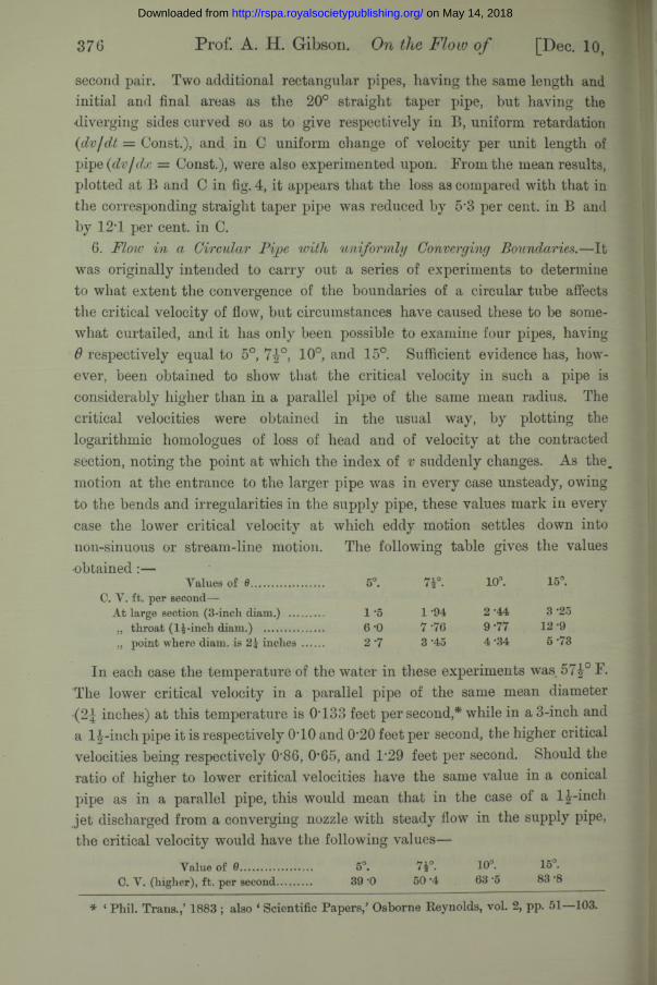
6. Flow in a Circular Pipe with uniformly Converging Boundaries.—It was originally intended to carry out a series of experiments to determine to what extent the convergence of the boundaries of a circular tube affects the critical velocity of flow, but circumstances have caused these to be somewhat curtailed, and it has only been possible to examine four pipes, having 6 respectively equal to 5°, 7|-°, 10°, and 15°. Sufficient evidence has, however, been obtained to show that the critical velocity in such a pipe is considerably higher than in a parallel pipe of the same mean radius. The critical velocities were obtained in the usual way, by plotting the logarithmic homologues of loss of head and of velocity at the contracted section, noting the point at which the index of v suddenly changes. As the_ motion at the entrance to the larger pipe was in every case unsteady, owing to the bends and irregularities in the supply pipe, these values mark in every case the lower critical velocity at which eddy motion settles down into non-sinuous or stream-line motion. The following table gives the values •obtained :—
Prof. A. H . Gibson. On Flow o f [Dec. 10,
Yalues of 6 ..................... 5°. 7 r . 10°. 15°.C. Y. ft. per second—
At large section (3-incli diam.) .......... 1 5 1 -94 2 -44 3-25„ throat (lj-inch diam.) ................. 6-0 7 -76 9-77 12 -9„ point where diam. is 2J inches ...... 2-7 3-45 4-34 5-73
In each case the temperature of the water in these experiments was 57|° F. The lower critical velocity in a parallel pipe of the same mean diameter
inches) at this temperature is 0T33 feet per second,* while in a 3-inch and a l|-inch pipe it is respectively 040 and 0*20 feet per second, the higher critical velocities being respectively 0'86, 0'65, and 1’29 feet per second. Should the ratio of higher to lower critical velocities have the same value in a conical pipe as in a parallel pipe, this would mean that in the case of a lj-inch jet discharged from a converging nozzle with steady flow in the supply pipe, the critical velocity would have the following values—
Value of 0.. 5°. 7a°- lO3- •C. V. (higher), ft. per second.......... 39 ’O 50 '4 63 •5 83 -8
* ‘ Phil. Trans.,’ 1883 ; also ‘ Scientific Papers,’ Osborne Reynolds, vol. 2, pp. 51—103.
on May 14, 2018http://rspa.royalsocietypublishing.org/Downloaded from
and would explain the glassy appearance of the high velocity jet leaving the nozzle of a Pelton wheel. Further experiments are, however, needed to settle this point and also to determine how, with the same values of but with different inlet and outlet diameters, the critical velocity depends on the latter factor.
7. Summary and Conclusions.—The following are the conclusions to be drawn from the experiments:—
(a) In a circular pipe with uniformly diverging boundaries, the total loss of head attains its minimum value with a value of 0 equal to about 5° 30'. Owing to the comparatively large effect of friction in a pipe having a small value of 0, the value giving the minimum loss of head will be somewhat less in larger pipes. (In large pipes of the type used in Venturi meters, experiment shows that this value is about 5° 6'.) As 0 is increased the loss of head, expressed as a percentage of (?q—v2)2/2# increases very rapidly from its minimum value of about 13*5 per cent, to a maximum of about 121 per cent, when 0 — 63°, afterwards diminishing to about 102 per cent, as 0 is increased up to 180°. Owing to the comparatively small value of the friction loss, as opposed to impact loss with values of 0 greater than about 8°, the latter values will presumably be the same for pipes of diameters varying largely from those used in the experiments.
(b) By making the pipe trumpet shaped so as to make uniformthroughout the pipe, the loss is in some cases increased, in others diminished. Only one such circular pipe was used, and here the loss was 23*5 per cent., as against 17'3 per cent, in a straight taper pipe of the same length and having 0 = 10°. In the case of a rectangular pipe, however, pipes having boundaries curved so as to make respectively = Const.) and(dv/dx = Const.) showed that the loss as compared with that in the corresponding straight taper pipe (0 = 20°) was reduced respectively by 5-3 and 12T per cent. Further experiments are desirable to determine the precise form of curve giving least loss of head in each case.
(c) The loss of head in a pipe of square section is greater—at the least 20 per cent, greater—than in a circular diverging pipe of the same length and same initial and final areas, while the minimum loss is apparently obtained when the angle between opposite faces of the pipe is approximately 4°.
(d) A change in the shape, as opposed to the area, of the cross-section of a pipe, leads to considerable loss of head. Thus by changing the section of a pipe from that of a square of 2*66 inches side to a rectangle 1*33 inches by 5*32 inches in a length of 9*94 inches, a loss of head equal to 0*484 v2/ 2g was experienced.
Water through Pipes , etc. on May 14, 2018http://rspa.royalsocietypublishing.org/Downloaded from
(e) "Where a rectangular pipe has one pair of sides parallel and the second pair uniformly diverging, the loss of head is much greater than in a circular pipe having the same length, and the same initial and final areas. The minimum loss is obtained with a value of d in the neighbourhood of 11°.
( / ) The critical velocity of flow in a circular pipe with uniformly converging boundaries is much greater than in a parallel pipe of the same mean diameter. The critical velocity increases rapidly with the angle of convergence, its lower value in the pipes considered (from 3 inches to 1^ inches diameter) at 57|° F., being as follows, at the point where the diameter is 2 \ inches:—
378 On the Flow of Water through Pipes and , etc.
e......................... 5°. 7t°. 10°. 15°.C. Y., ft. per second................. 2 *7 3 *4 4 *3 5 *7
The lower critical velocity in a parallel pipe of the same mean diameter at this temperature is 0T33 foot per second.
In conclusion, the author would acknowledge his indebtedness to the Government Grant Committee of the Eoyal Society, by whose grant in aid the provision of the apparatus used in these experiments was made possible.
on May 14, 2018http://rspa.royalsocietypublishing.org/Downloaded from