On the hydraulic efficiency of distributed detention basins: a case of study PIERFRANCESCO RUFOLO, GIACOMO VICCIONE, PAOLO VILLANI Dipartimento di Ingegneria Civile (DICIV) Università di Salerno via Giovanni Paolo II, 132, 84084 Fisciano (SA) ITALY [email protected]http://www.unisa.it/docenti/giacomoviccione/en/index Abstract: - This work presents a computer assisted methodology for designing a distributed system of rainstorm detention basins. The procedure is based on the condition that water discharge must be lower than a fixed threshold limit at the downstream end of the system, for a given input hydrograph flowing over it. Results were obtained for a portion of the Solofrana brook between Solofra and Pandola municipalities, Campania Region, Southern Italy. Flow rates were first determined for a return period of 100 years by applying the VAPI geomorphoclimatic model. Then, basin volumes were determined on the condition that the maximum discharge had not exceeding the limit of 60m 3 /s, as imposed by the Hydrogeological Structure Plan (PSAI) of the Central Campania Basin Authority. Key-Words: - detention basins, retarding basins, flooding, flood lamination, flood risk 1 Introduction Periods of intense rainfall can sometimes overload the river network causing water flooding. Related events pose not only potential hazards for human beings, livestock farming and infrastructures. They are dangerous as well when flowing water is polluted. After severe rainstorms, on September 1 st , 2014, the Solofrana river (Campania Region, Italy) flooded, causing land overflowing nearby the municipality of Montoro and the closure of the local highway for the next two days, due to the large amount of debris released on the roadway. Detected concentrations of beryllium, tin and other heavy metals and hydrocarbons, in some cases much higher than limits provided by the Italian legislation, the Mayor of Montoro ordered not to consume food or drink that came in contact with floodwaters as well as the stopping of any cultivation for farms especially struck by the event. Storage areas, known as detention or retarding basins consist of an effective method for storing such overflows. They are basically dry ponds during dry periods, surrounded by embankments with one or more flow weirs. They are designed to reduce extreme flood peaks corresponding a to return period ranging from 100 to 500 years. During dry periods, they can be used as recreation areas or parks. Conversely, during extreme rainfall events they behave as water storing, hence reducing the extend and magnitude of floods events. In this work we analyze the effect of a distributed system of on-line detention basins in term of peak reduction. Such a solution is adopted sometimes in Fluvial Eco-Hydraulics, as it features on one hand a lower impact on the ecosystem than the off-line ones. On the other hand, they form wetlands over the river, favoring the growing of aquatic plants, biodiversity and animal colonization. Examples worth to be mentioned of systems of flood retarding basins are those managed by the Melbourne water (200 interconnected holding ponds within the local drainage system), by the Miami Conservancy District (MCD, five storage areas on a 141.6km 2 water network). A local example is represented by the flood reduction system realized on the Lura brook, between Bregnano and Lomazzo municipalities, Northern Italy. It is about three detention basins that globally form a fluvial park. The methodology proposed cionsists of a distributed hydrological model for flood inundation, coupled with a geographical information system (GIS)-based raster model [1-2]. 2 Materials 2.1 The Solofrana drainage basin The area object of the present study is inside the 190 km 2 drainage basin of the Solofrana creek at Pandola (Figure 1, coloured area). Starting from the Campania Regional Technical Map to scale 1:5000 (CTR5000), level curves were interpolated in the Advances in Environmental and Geological Science and Engineering ISBN: 978-1-61804-314-6 348
Transcript
On the hydraulic efficiency of distributed detention basins: a case of study
PIERFRANCESCO RUFOLO, GIACOMO VICCIONE, PAOLO VILLANI
Dipartimento di Ingegneria Civile (DICIV) Università di Salerno
via Giovanni Paolo II, 132, 84084 Fisciano (SA) ITALY
[email protected] http://www.unisa.it/docenti/giacomoviccione/en/index Abstract: - This work presents a computer assisted methodology for designing a distributed system of rainstorm detention basins. The procedure is based on the condition that water discharge must be lower than a fixed threshold limit at the downstream end of the system, for a given input hydrograph flowing over it. Results were obtained for a portion of the Solofrana brook between Solofra and Pandola municipalities, Campania Region, Southern Italy. Flow rates were first determined for a return period of 100 years by applying the VAPI geomorphoclimatic model. Then, basin volumes were determined on the condition that the maximum discharge had not exceeding the limit of 60m3/s, as imposed by the Hydrogeological Structure Plan (PSAI) of the Central Campania Basin Authority. Key-Words: - detention basins, retarding basins, flooding, flood lamination, flood risk
1 Introduction Periods of intense rainfall can sometimes overload the river network causing water flooding. Related events pose not only potential hazards for human beings, livestock farming and infrastructures. They are dangerous as well when flowing water is polluted. After severe rainstorms, on September 1st, 2014, the Solofrana river (Campania Region, Italy) flooded, causing land overflowing nearby the municipality of Montoro and the closure of the local highway for the next two days, due to the large amount of debris released on the roadway. Detected concentrations of beryllium, tin and other heavy metals and hydrocarbons, in some cases much higher than limits provided by the Italian legislation, the Mayor of Montoro ordered not to consume food or drink that came in contact with floodwaters as well as the stopping of any cultivation for farms especially struck by the event.
Storage areas, known as detention or retarding basins consist of an effective method for storing such overflows. They are basically dry ponds during dry periods, surrounded by embankments with one or more flow weirs. They are designed to reduce extreme flood peaks corresponding a to return period ranging from 100 to 500 years.
During dry periods, they can be used as recreation areas or parks. Conversely, during extreme rainfall events they behave as water storing, hence reducing the extend and magnitude of floods events.
In this work we analyze the effect of a distributed system of on-line detention basins in term of peak reduction. Such a solution is adopted sometimes in Fluvial Eco-Hydraulics, as it features on one hand a lower impact on the ecosystem than the off-line ones. On the other hand, they form wetlands over the river, favoring the growing of aquatic plants, biodiversity and animal colonization.
Examples worth to be mentioned of systems of flood retarding basins are those managed by the Melbourne water (200 interconnected holding ponds within the local drainage system), by the Miami Conservancy District (MCD, five storage areas on a 141.6km2 water network). A local example is represented by the flood reduction system realized on the Lura brook, between Bregnano and Lomazzo municipalities, Northern Italy. It is about three detention basins that globally form a fluvial park.
The methodology proposed cionsists of a distributed hydrological model for flood inundation, coupled with a geographical information system (GIS)-based raster model [1-2]. 2 Materials 2.1 The Solofrana drainage basin The area object of the present study is inside the 190 km2 drainage basin of the Solofrana creek at Pandola (Figure 1, coloured area). Starting from the Campania Regional Technical Map to scale 1:5000 (CTR5000), level curves were interpolated in the
Advances in Environmental and Geological Science and Engineering
ISBN: 978-1-61804-314-6 348
ArcGIS ® environment [3], obtaining a digitalized model consisting of irregular triangular grid elements (TIN). TIN was then converted into a regular mesh grid (GRID), formed by quadratic elements 5m wide, a size which correspond to the maximum level of detail compatibly with a CTR5000 map. Such an intermediate model then needed to be processed to eliminate non physical hollows - known as pits - with the fill function, under ArcGIS®. The obtained model is defined as depressionless Digital Terrain Model (DTM), shown in Figure 2.
At this stage, the drainage network and the drainage divide were defined through the Spatial analyst tools under the Hydrology section of the software. More in detail, we used the single flow direction algorithm and the flow accumulation tool for the former and the watershed tool for the latter. The final obtained result is shown in Fig. 2. 2.2 The current situation According to the Regional Department of Soil Defense, next indicated ad R.D.S.D. [4], the maximum allowed discharge at Pandola is fixed as Qlim=60m3/s, but the flowing 100-years discharge, evaluated by means of the VAPI model [5], is Q100=300m3/s. At the moment, a detention basin exists at Pandola, of 320000m3, and two other catch basins (Pozzello, 168000m3 and San Bartolomeo, 480000m3) are planned [4] (see Fig. 3). We propose an alternative solution, based on the following observation: under steady flow conditions if no storing areas are considered, the simulation of the Solofrana creek hydraulic profile (obtained with the software HEC RAS ® [6]) shows that it is mostly interested by overflowing (Fig. 4.a). It suggests the spatial deployment of a greater number of less massive catch basins than those expected in the regional plan. We then considered in our study a total number of six storing areas. Subsequent implications are next discussed. 3 The proposed system of catch basins 3.1 Volume definition of the catch basins Once the spatial distribution of suitable storing areas was spatially allocated as function of topography and urbanization, see Fig. 4.b, the next step was then to define the storing volumes involved. This was done by simulating them as off-line drainage basins with the software HEC RAS®, under non steady conditions. The system was then judged to be
hydraulically efficient when the flow discharge at the downstream end of it was under Qlim.
The connection to the Solofrana brook was realized by linking them with rectangular weirs, whose length was assumed equal to the longitudinal extension of each basin. The relationships between storing volumes and water levels V(h), i.e. the basin laws, were defined by means of the software ArcGIS®. As an example, in Fig. 5 is shown the basin law for the San Bartolomeo catch basin.
We gave at upstream end of the system an input hydrograph of triangular shape, the peak discharge being Q100 and a base flow of 0.10·Q100. Maximum water stages are shown in Fig. 4.b. As can be observed, the presence of a distributed system of catch basins allows the water profile to be under the river banks.
Fig. 1. Digital Terrain Model (DTM) of the Solofrana drainage basin. The area covered by this investigation is coloured with topographic height.
Fig. 2. Digital Terrain Model (DTM) of the Solofrana drainage basin above the Pandola river section. Definition of the watershed and the drainage network (thin black lines) in ArcGIS.
2 6 km41
Advances in Environmental and Geological Science and Engineering
ISBN: 978-1-61804-314-6 349
Fig. 6 shows the corresponding output hydrograph and water levels at the downstream end of the system.
The limit Qlim is guaranteed. The procedure let the definition of basin volumes given in Table 1.
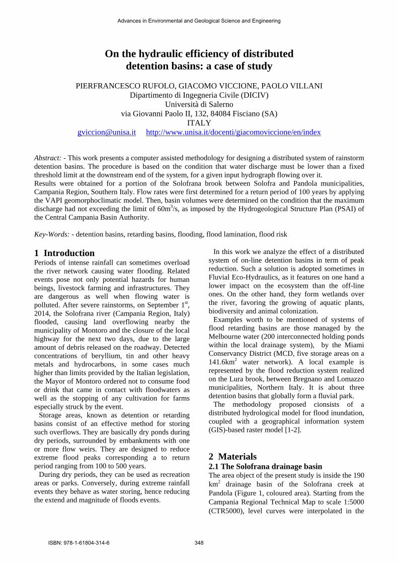
Fig. 3. The proposed spatially distributed lamination system: 1. Pozzello catch basin (already considered in R.D.S.D.). 2. Torchiati catch basin (not included in R.D.S.D.). 3. San Pietro monte catch basin (not included in R.D.S.D.). 4. San Pietro valle catch basin (not included in R.D.S.D.). 5. San Bartolomeo catch basin (already considered in G.P.F.S). 6. Pandola catch basin (already considered in R.D.S.D.).
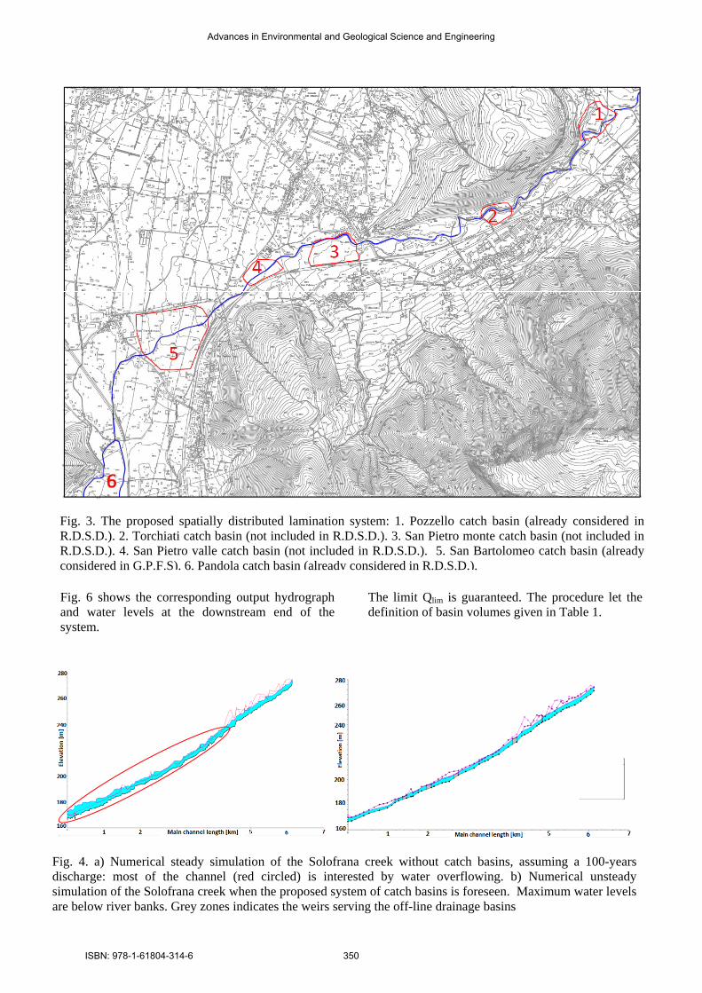
Fig. 4. a) Numerical steady simulation of the Solofrana creek without catch basins, assuming a 100-years discharge: most of the channel (red circled) is interested by water overflowing. b) Numerical unsteady simulation of the Solofrana creek when the proposed system of catch basins is foreseen. Maximum water levels are below river banks. Grey zones indicates the weirs serving the off-line drainage basins
Advances in Environmental and Geological Science and Engineering
ISBN: 978-1-61804-314-6 350
Table 1. Main characteristics of the designed system of detention basins
Basin name Storing volume
[m3]
Maximum water surface
[m2] Pozzello 168000 54000 Torchiati 60000 28000
S. Pietro monte 80000 70000 S. Pietro valle 106000 37000 S. Bartolomeo 560000 211000
Fig. 5. The basin law of the San Bartolomeo catch basin.
Fig. 6. Output flow hydrograph and water levels at the Pandola river station. 4 Conclusions In this work a computer assisted methodology for the design of a distributed system of catch basins was presented and discussed for a case study. The procedure is based on the preliminary definition of the Digital Terrain Model (DTM), water network and basin laws by means of the ArcGIS software. Hydraulic performance was then derived by implementing system geometry in the HEC RAS software, giving the detention basins as off-line storing volumes. The procedure is proved to be reliable yet simple to apply. It allowed to obtain a solution not only hydraulically effective, but also with reduced environmental impact by creating a network of small temporary wetlands.
References: [1] Dutta D., Herath S. and Musiake K., An
application of a flood risk analysis system for impact analysis of a flood control plan in a river basin. Hydrol. Process., Vol. 20, 2006, pp. 1365–1384, doi: 10.1002/hyp.6092
[2] Takasao T., Shiiba M. and Tachikawa Y., Real-time integrated operating system of retarding basin sluice ways. IAHS Proceedings and Reports, Vol. 213, 1993, pp. 403-410.
[3] ESRI 2011. ArcGIS Desktop: Release 10. Redlands, CA: Environmental Systems Research Institute.
[4] Agenzia Regionale Campana Difesa Suolo 2012, Grande progetto completamento della riqualificazione e recupero del fiume Sarno.
[5] Rossi F. and Villani P., Regional flood estimation methods, in Coping with Flood, G. Rossi, N. Harmancioglu e V. Yevjevich, 135-170, Kluwer Academic, Dordrecht, (NE), 1994.
[6] U.S. Army Corps of Engineers, Hydrologic Engineering Center, River Analysis System – Hydraulic Reference Manual 4.1, 2010
Advances in Environmental and Geological Science and Engineering