“ On the integration of terrestrial and satellite systems in future 5G networks: a waveform perspective " A. Guidotti (Univ. of Bologna), G. Colavolpe (Univ. of Parma), A. Vanelli-Coralli (Univ. of Bologna), and G. E. Corazza (Univ. of Bologna) Joint Expert Group and Vision Group Workshop 2016 Bologna, March 16, 2016
Transcript
“On the integration of terrestrial and satellite systems in future 5G networks: a waveform perspective"
March 16,2016 Ontheintegrationof terrestrialandsatellitesystemsinfuture5Gnetworks:awaveformperspective 6
24
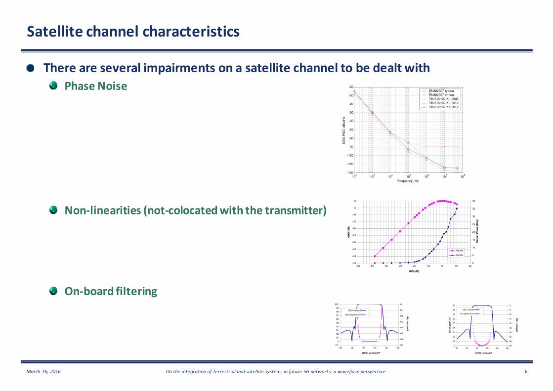
Figure 2-14: Phase noise power spectral density masks for the DTH service
In order to limit the number of phase noise masks to be used, a proposal is to mandate the “TM-S20102 Ka 2012” mask as first priority and the “TM-S20102 Ku 2000” as second priority but only for symbol rates lower than 36Mbaud (which is most likely the highest conceivable symbol rate through a 36 MHz transponder – 40 MHz spacing) . In summary, the two phase noise masks to be used are:
Table 2-5: Phase noise masks to be used for the DTH broadcasting services
The introduction of the phase noise in the channel mask requires defining an absolute value of transponder frequency spacing for assessing the impact of phase noise to the
102 103 104 105 106 107 108-120
-110
-100
-90
-80
-70
-60
-50
-40
-30
-20
Frequency, Hz
SS
B P
SD
, dB
c/H
z
EN302307 typicalEN302307 criticalTM-S20102 Ku 2000TM-S20102 Ku 2012TM-S20102 Ka 2012
11
Figure 2-2: Typical TWTA Ground Station AM/AM and AM/PM characteristics
The operational point of the HPA (IBO/OBO) has to be selected in order to comply with typical out-of-band emissions recommended by the satellite operator. A conservative working assumption is to limit the spectrum regrowth spill-over power at -30 dB. However, to be noted that in certain cases the satellite operators are prepared to relax their requirements on a case-by-case basis, so higher out-of-band power levels might be acceptable.
IMUX and OMUX 2.2
The IMUX and OMUX filters specified in [1] and reported here for convenience are identified for the channel model.
0
5
10
15
20
25
30
35
40
-45
-40
-35
-30
-25
-20
-15
-10
-5
0
-60 -50 -40 -30 -20 -10 0 10 20
Out
put P
hase
[Deg
]
OB
O [d
B]
IBO [dB]
AM/AM and AM/PM TWTA Characteristics
AM/AM
AM/PM
12
Figure 2-3: IMUX Amplitude and Group Delay response model as in [1]
Figure 2-4: OMUX Amplitude and Group Delay response model as in [1]
-10
0
10
20
30
40
50
60
70
80
90
100
-70
-60
-50
-40
-30
-20
-10
0
-50-30-10103050
Rejection (dB)
Frequency (MHz)
IMUX Ku-band (36 MHz)
Rejection (dB)
Group Delay (ns)
00
10
20
30
40
50
60
70
80
90
-45
-40
-35
-30
-25
-20
-15
-10
-5
0
-50-30-10103050
Group Delay (ns)
Rejection (dB)
Frequency (MHz)
OMUX Ku-band (36 MHz)
Rejection (dB)
Group Delay (ns)
12
Figure 2-3: IMUX Amplitude and Group Delay response model as in [1]
Figure 2-4: OMUX Amplitude and Group Delay response model as in [1]
March 16,2016 Ontheintegrationof terrestrialandsatellitesystemsinfuture5Gnetworks:awaveformperspective 7
Optimal Carrier Spacing
Filtering away side lobes
Standard DVB-S2 carrier spacing Carrier spacing with Filtering Technology
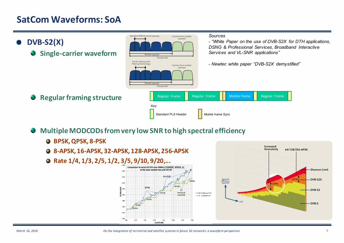
Improvement 2: Advanced Filtering Technologies for Improved Carrier Spacing
The second innovation deals with noise levels (side lobes) on both sides of the carrier. These side lobes prevent putting satellite carriers close to each other.Applying advanced filter solutions has an immediate effect on bandwidth savings as the spacing between carriers can be put as close as 1.05 times their symbol rates (or even closer in some specific use cases).
It is important to note that even with 35%, 25% and 20% Roll-offs better filtering results are obtained. The improvement has the best effect when the ground station High Power Amplifier (HPA) is driven close to saturation. The spectral regrowth at a frequency offset (= symbol rate) will be lower with the better filtering. Meaning, at saturation the result will have a much cleaner signal spectrum.
Improvement 3: Supporting Different Network Configurations
The Roll-Off and filtering innovations within the new standard can be applied in satellite links with single carriers (mainly Roll-Off effect), multiple carriers (Filtering and Roll-Off effects) or carriers sharing the same transponder with other providers. In the latter case DVB-S2X carriers
can easily co-exist with adjacent carriers from other operators within the same transponder. The improved roll-offs and filtering technologies are only applied on the allocated carriers. Neighboring carriers will not be affected and do not notice any form of interference.
Shared Transponder Support
Standard DVB-S2 carrier spacing
Rented capacity
Rented capacity
Transponder
Transponder
Carrier spacing with Filtering Technology
Carriers from anotheroperator
Carriers from anotheroperator
White Paper DVB-S2X Demystified
5
S2 Extensions MODCOD and FEC Upgrades
Improvement 4: Increased Granularity in MODCODs
As a next step the DVB-S2X standard increase the modulation and coding (MODCOD) schemes and Forward Error Correction (FEC) choices compared to DVB-S2.By introducing an increased granularity the highest resolution for optimal modulation in all circumstances can be provided. The current DVB-S2 quantization steps are quite far apart. By adding granularity in the upcoming standard the service provider can further optimize the satellite link depending on the application. In combination with Adaptive Coding and Modulation (ACM), where the highest MODCOD is selected automatically, full efficiency can be gained. The amount of MODCODs has grown from 28 in DVB-S2 up to 112 in DVB-S2X bringing efficiency as close to the theoretical Shannon limit as possible.
Improvement 5: Higher Modulation Schemes up to 256APSK
Adding higher modulation schemes such as 256APSK proves to be useful considering the professional applications that work with improved link budgets provided by, for example, bigger antennas (more powerful satellites that become available). Newtec sees the 32APSK boundary being reached frequently with its auto-adaptive FlexACM® technology during clear weather conditions. In these situations having higher modulation schemes as 64, 128 and 256APSK is highly beneficial. When combining the increased granularity (MODCODs and FECs) and higher order modulation immediate efficiency gains up to 51% can be achieved compared to DVB-S2 (see figure below).
White Paper DVB-S2X Demystified
DVB-S2X compared to DVB-S2 (64/128/256APSK & increased granularity)
Increased Granularity
Spectral Efficiency(bps/Hz)
C/N
64/128/256 APSK
+27%
+51%
Shannon Limit
DVB-S2X
DVB-S2
DVB-S
6
Figure 1: DVB-S2 and DVB-S2X spectral
Figure 1 illustrates the simulated performanceDVB-S2 is indicated by the green plot and the granularity effect. Figure 1 shows that points fall on the same ideal dotted lines. DVB-S2X adds new 8PSK MODCODs in the SNR range In addition, whilst 16APSK is optional in S2X mandates the use of 16APSK implementation of 16APSK in DVB-S2X represents a mandatory DVB-S2 specification in the SNR region around 10satellite platforms, typically characterised by a C/I available when operating in channels withIn the range of SNR appropriate for broadcast applications, the DVBShannon capacity curve within a dB or soThe performance of a satellite broadcast service is characterised by a link analysis calculation (the link budget). This predicts the performance of the serviceperformance is often described in terms of adetermined by the SNR characteristics of theThe available SNR is not a constant over acontour maps and the characteristics of the transmit and receive earth stations. In addition there is a temporal variation caused by the prevailing weather conditions in the uplink and downlink regions at thA broadcaster computes the minimum available SNR in the year) using appropriate statistical modelling techniques to P.841 as a guide, although other modelling techniques also existDue to its increased MODCOD granularity, DVBoptimising system performance for specific SNR levels.As shown in Figure 1, any SNR can be matched by continuous lines with the stair-case shape connecting the simrate. The figure shows that DVB-S2X, with its finer MODCOD granularity, while DVB-S2 with its coarser granularity suffers from
3 Simulated Roll-off 5%, even though this is not available in DVB4 It should be noted that in the SNR range of interest for broadcasting, each tenth of dB corresponds approximately to 1% of sp5 The continuous lines are constructed as follows: starting from a simulated point at the maximum allowed symbol
efficiency are progressively lowered, and the required SNR reduces by 10Log[Rs/Rs(max)]; when the lower effpreferable in terms of spectral efficiency and SNR, it is selected (the flat part of the staircase). When the symbol rate cansteps become vertical and the maximum granularity gain approaches 14%.
pectral efficiency, at the same roll-off and symbol-rate (channel model A)SNR range typical for broadcasting.
he simulated performance of channel model A in the SNR range of interest for broadcast services.lot and DVB-S2X by the blue plot. The same roll-off is assumed
shows that DVB-S2X and DVB-S2 share a large number of MODCODs, therefore points fall on the same ideal dotted lines.
S2X adds new 8PSK MODCODs in the SNR range from 6 to 8.5 dB covered in DVB-is optional in DVB-S2 for DTH legacy receivers (see violet triangles in
(adding new MODCODs) in the SNR region 9 to S2X represents a significant capacity increase of around 5%
S2 specification in the SNR region around 10 dB (which is a challenging satellite platforms, typically characterised by a C/I of about 13 dB from adjacent satellites).
with SNR levels better than 10 dB. In the range of SNR appropriate for broadcast applications, the DVB-S2X curve faithfully follows the slope of ideal
within a dB or so (4). satellite broadcast service is characterised by a link analysis calculation (the link budget). This
service in terms of receive margin (in dB) above the required thresholdperformance is often described in terms of an availability figure (% availability per annum).determined by the SNR characteristics of the transmission channel to the specific downlink installation and location.The available SNR is not a constant over any given region and is dependent upon the satellite
the characteristics of the transmit and receive earth stations. In addition there is a temporal variation caused by the prevailing weather conditions in the uplink and downlink regions at the time of the transmission.A broadcaster computes the minimum available SNR in the service area for a target service availability (e.g. 99
appropriate statistical modelling techniques (for example, see ITU-R Recommendations P.618, although other modelling techniques also exist).
Due to its increased MODCOD granularity, DVB-S2X offers greater flexibility to the broadcaster with regard to optimising system performance for specific SNR levels.
any SNR can be matched by DVB-S2 and DVB-S2X (as indicated by thecase shape connecting the simulated points (5)), by fine-tuning the transmitted symbol
S2X, with its finer MODCOD granularity, closely matches the ideal blue dotted line, er granularity suffers from a larger “ripple” compared to the ideal dotted green line.
off 5%, even though this is not available in DVB-S2
It should be noted that in the SNR range of interest for broadcasting, each tenth of dB corresponds approximately to 1% of sp
The continuous lines are constructed as follows: starting from a simulated point at the maximum allowed symbol-rate, the symbolefficiency are progressively lowered, and the required SNR reduces by 10Log[Rs/Rs(max)]; when the lower effpreferable in terms of spectral efficiency and SNR, it is selected (the flat part of the staircase). When the symbol rate can
and the maximum granularity gain approaches 14%.
Page 4 of 14
rate (channel model A), in the
of channel model A in the SNR range of interest for broadcast services. off is assumed (3), to better clarify
S2 share a large number of MODCODs, therefore their
-S2 with lower granularity. (see violet triangles in Figure 1), DVB-
to 12 dB. The mandatory significant capacity increase of around 5% over the original
dB (which is a challenging operating area for current Even further increases are
faithfully follows the slope of ideal
satellite broadcast service is characterised by a link analysis calculation (the link budget). This in terms of receive margin (in dB) above the required threshold and the
n availability figure (% availability per annum). The performance is channel to the specific downlink installation and location.
satellite uplink and downlink the characteristics of the transmit and receive earth stations. In addition there is a temporal variation
e time of the transmission. service area for a target service availability (e.g. 99.9% of
R Recommendations P.618 and P.837
S2X offers greater flexibility to the broadcaster with regard to
as indicated by the blue and green tuning the transmitted symbol-
matches the ideal blue dotted line, larger “ripple” compared to the ideal dotted green line.
It should be noted that in the SNR range of interest for broadcasting, each tenth of dB corresponds approximately to 1% of spectral efficiency
rate, the symbol-rate and spectral efficiency are progressively lowered, and the required SNR reduces by 10Log[Rs/Rs(max)]; when the lower efficient MODCOD becomes preferable in terms of spectral efficiency and SNR, it is selected (the flat part of the staircase). When the symbol rate cannot be finely tuned, the
Page 7 of 14
transmission overhead to all receive terminals. Considering the fact that mobile and VL-SNR terminals are likely to be only a small minority of the population in any given network, another less onerous solution was deemed to be required in the implementation of the DVB-S2X header architecture in order to economically support the additional modes. An alternative approach which allows regular terminals to use the original DVB-S2 90-symbol PLS Header with only minimal modification to support the larger number of DVB-S2X MODCODs has therefore been adopted. As shown in Figure 4, terminals with higher Es/No thresholds will continue to use the 90-symbol PLS header (i.e. the regular frame sync), and are therefore not penalised by accepting mobile or VL-SNR terminals into the network. Each code frame intended for a mobile or VL-SNR terminal also contains the original 90-symbol PLS header which, in this case, is used to signal to the normal terminals that the following is a frame for a VL-SNR terminal, and specifies the length of the code frame (only two lengths are allowed even though nine VL-SNR MODCODs are defined). A regular terminal can then skip this code frame and look for the next PLS header at the corresponding time with no disruption of frame synchronisation.
Figure 4: Time-multiplex format of a DVB-S2 extension carrier consisting of both regular code frames and code frames for VL-SNR terminals
In Figure 4, the additional VL-SNR frame synchronisation serves two purposes: • to provide burst mode synchronisation of the VL-SNR frames, and • to identify the specific VL-SNR MODCOD for the mobile terminals.
This is accomplished by a set of specifically designed unique words (UW), each identifying one of the nine MODCODs, plus a dummy frame. These unique words are generated from a single mother sequence of 900 symbols, such that an efficient correlation algorithm can be used to detect both the presence the signal and, at the same time, identify the MODCOD. The length of the UW is selected to provide more than adequate margin to achieve synchronisation at the lowest operating SNR range without introducing excessive overhead. For most of the VL-SNR range, π/2-BPSK modulation is used. The two lowest MODCODs are further spread by a factor of 2. To interoperate with legacy DVB-S2 receivers in VCM modes, the length of LDPC codes are modified so that the frame size of the VL-SNR MODCODs, including the 900-symbol frame sync and pilots, is the same as either a QPSK or 16APSK modulated DVB-S2 MODCOD with pilots.
Sharper roll-off The gains achieved from sharper roll-off depend upon the flexibility the operator has to set the optimum symbol rate and the constraints imposed by the satellite operator in terms of uplink spectral mask. Assuming that the operator is totally free to optimise the symbol-rate to increase the spectral efficiency (as illustrated in Figure 7), and using the DTH satellite channel model B and an enhanced receiver, the TM-S2 has calculated that there is no clear benefit to use sharper roll-offs (see Figure 5). Although sharper roll-offs allow higher symbol rates (37 Mbaud) the additional capacity gain is below 2% compared with a 20% roll-off and symbol-rate of 34 Mbaud. Nevertheless, increasing symbol rate may generate interference in adjacent channels, which can be better controlled by sharp roll-offs. New simulation results based on the satellite channel model described in the User Guidelines document TR 102376-2 which includes an additional increase of +8 dB in the uplink ACI and with a symbol rate of 34 Mbaud, have shown that a roll-off of 20% can provide 0.1 - 0.2 dB better performance when compares with 5% roll-off using a fractionally spaced equaliser in the receiver. Note that these results did not cover higher symbol rates. In cases where the satellite operators limit the usable bandwidth (Bu) by invoking the (1+roll-off) (8) rule, then maximum transmittable symbol-rate becomes Bu/(1+roll-off). In this scenario, assuming that within the usable bandwidth, transponder bandwidth limitations are not generating significant distortions (i.e. we are operating as channel model A), then the sharper roll-offs will allow for a proportional increase of the transmitted symbol rate. In this case the spectral efficiency gains roughly account for half of the roll-off difference. This is because the other half of the gain is
8 The transmitted symbol rate Rs must be lower to BW/(1+roll-off) , where BW is the usable bandwidth.
Regular Frame Regular Frame
Standard PLS Header
Key:
Mobile frame Sync
Mobile Frame
Regular Frame
Sources- “White Paper on the use of DVB-S2X for DTH applications,DSNG & Professional Services, Broadband InteractiveServices and VL-SNR applications”