1 On the Optimization of Survivable Mesh Long-Reach Hybrid WDM-TDM PONs Dieu Linh Truong, Phan Thuan Do, and Anh T. Pham, Senior Member, IEEE Abstract—Long-reach hybrid wavelength-division multi- plexing (WDM) and time-division multiplexing (TDM) passive optical networks (PONs) allow deploying access networks for remote service areas with thousands of customers. Typically, several long fiber cables are run between the central office of the service provider and each service area in order to feed the service area with data flows. In the service area, array waveguide gratings (AWGs) multiplex and demultiplex wavelengths; then splitters split wavelengths in order to serve multiple optical network units. This paper proposes to use a mesh topology in service areas, i.e. AWGs can feed each other. This architecture has two main advantages. First, mesh linkages between AWGs make the network structure more robust with a high possibility to integrate survivable schemes. Second, fewer fibers are required between the central office (CO) and service areas leading to a reduction of total length of fiber deployment; and consequently a reduction of fiber installation and maintenance costs. We support this proposal by showing that i) the proposed archi- tecture is feasible provided some modification/combination of conventional PON devices; and ii) while using our optimal and heuristic algorithms for designing survivable long-reach hybrid WDM-TDM PONs, most of these PONs should use the mesh topology in order to minimize the total length of fiber deployment. Index Terms—Long-reach Passive optical network (PON); Wavelength-division multiplexing (WDM); Time-division mul- tiplexing (TDM); Survivability; Mesh networks; Heuristic algorithms. I. I NTRODUCTION Passive optical network (PON) technology is widely ac- cepted as the solution for deploying access networks since it allows sharing single optical fiber among multiple cus- tomers at low cost. More recently, the integration of both wavelength-division multiplexing (WDM) and time-division multiplexing (TDM) to PON has been introduced under the name hybrid WDM-TDM PON [1]. In such PON, multiple wavelengths over the same fiber are exploited to carry traffic from an optical line terminal (OLT) in a central office (CO) to a point close to the customers area. Then, an arrayed waveguide grating (AWG) [2] demultiplexes the signal into different wavelengths, each of which goes to a different direction. Finally, each wavelength is split again by a passive splitter before ending at optical network units (ONU) in customer premises. It is shown in [3] that more than 4,000 customers can be served by a branch of a hybrid WDM-TDM PON. The term long-reach PON [4] refers to the PON that covers a long distance. Customers are regrouped in service areas that are 20 to 100 km away from the CO. They share Dieu Linh Truong is with School of Information and Commu- nication Technology, Hanoi University of Science and Technology, Vietnam. Email: [email protected] (corresponding author) Phan Thuan Do is with School of Information and Communication Technology, Hanoi University of Science and Technology, Vietnam. Email: [email protected]Anh T. Pham is with the Computer Communications Lab., Uni- versity of Aizu, Japan. Email: [email protected]extended fibers to connect to CO. Long-reach hybrid WDM- TDM PON [3] at the same time covers a long distance and serves numerous customers thanks to multiple wavelengths. OLTs remain in CO on the service provider side while AWGs, splitters and ONUs reside in service areas. The diameter of a service area could be a few kilometers. OLT node at central office AWG-1 SP-1 AWG-2 SP-2 SP-3 SP-4 SP-5 AWG-3 SP-7 SP-6 AWG-4 service area ONU-9 ONU-1 ONU-2 ONU-3 ONU-4 ONU-5 ONU-6 ONU-7 ONU-8 ONU-10 ONU-11 ONU-12 ONU-13 ONU-14 Fig. 1. Mesh hybrid WDM-TDM PON model. PON splitters are usually arranged in star/tree; however, splitters and/or AWGs may be connected in a ring for pro- viding better reliability [5]. ONUs and splitters can also be organized in a mesh topology as in the light-mesh model proposed in [6]. However, in this paper, we consider another mesh topology for deploying long-reach hybrid WDM-TDM PON, where AWG nodes can be connected to each other (see Fig.1). This mesh topology has been initially proposed in [7]. In this topology, each AWG node has N × N ports (i.e., N in- ports and N out-ports). Each port can receive and transmit a waveband instead of a single wavelength. In addition, each AWG node must be capable to forward wavelengths in a relatively arbitrary way between in-ports and out-ports. Although conventional N ×N AWG proposed by Dragon in [8] (see Fig. 2(b) for an example) can demultiplex wavelengths from an input waveband to different out-ports, it does not allow arbitrary wavelength commutation. We will show in Section II that by combining several conventional 1 × N AWGs (see Fig. 2(a)) and N × N AWGs together in cascade, we can produce a totally passive waveband MUX/DEMUX that performs an expected wavelength commutation. Such waveband MUX/DEMUX should be used instead of AWG in the mesh WDM-TDM PONs. Readers are referred to references [2], [9], and [10] for waveband MUX/DEMUXs
Transcript
1
On the Optimization of Survivable Mesh Long-ReachHybrid WDM-TDM PONs
Dieu Linh Truong, Phan Thuan Do, and Anh T. Pham, Senior Member, IEEE
Abstract—Long-reach hybrid wavelength-division multi-plexing (WDM) and time-division multiplexing (TDM) passiveoptical networks (PONs) allow deploying access networks forremote service areas with thousands of customers. Typically,several long fiber cables are run between the central officeof the service provider and each service area in order tofeed the service area with data flows. In the service area,array waveguide gratings (AWGs) multiplex and demultiplexwavelengths; then splitters split wavelengths in order toserve multiple optical network units. This paper proposesto use a mesh topology in service areas, i.e. AWGs can feedeach other. This architecture has two main advantages. First,mesh linkages between AWGs make the network structuremore robust with a high possibility to integrate survivableschemes. Second, fewer fibers are required between thecentral office (CO) and service areas leading to a reductionof total length of fiber deployment; and consequently areduction of fiber installation and maintenance costs. Wesupport this proposal by showing that i) the proposed archi-tecture is feasible provided some modification/combinationof conventional PON devices; and ii) while using our optimaland heuristic algorithms for designing survivable long-reachhybrid WDM-TDM PONs, most of these PONs should use themesh topology in order to minimize the total length of fiberdeployment.
Passive optical network (PON) technology is widely ac-cepted as the solution for deploying access networks sinceit allows sharing single optical fiber among multiple cus-tomers at low cost. More recently, the integration of bothwavelength-division multiplexing (WDM) and time-divisionmultiplexing (TDM) to PON has been introduced under thename hybrid WDM-TDM PON [1]. In such PON, multiplewavelengths over the same fiber are exploited to carry trafficfrom an optical line terminal (OLT) in a central office (CO)to a point close to the customers area. Then, an arrayedwaveguide grating (AWG) [2] demultiplexes the signal intodifferent wavelengths, each of which goes to a differentdirection. Finally, each wavelength is split again by a passivesplitter before ending at optical network units (ONU) incustomer premises. It is shown in [3] that more than 4,000customers can be served by a branch of a hybrid WDM-TDMPON.
The term long-reach PON [4] refers to the PON thatcovers a long distance. Customers are regrouped in serviceareas that are 20 to 100 km away from the CO. They share
Dieu Linh Truong is with School of Information and Commu-nication Technology, Hanoi University of Science and Technology,Vietnam. Email: [email protected] (corresponding author)
Phan Thuan Do is with School of Information and CommunicationTechnology, Hanoi University of Science and Technology, Vietnam.Email: [email protected]
Anh T. Pham is with the Computer Communications Lab., Uni-versity of Aizu, Japan. Email: [email protected]
extended fibers to connect to CO. Long-reach hybrid WDM-TDM PON [3] at the same time covers a long distance andserves numerous customers thanks to multiple wavelengths.OLTs remain in CO on the service provider side while AWGs,splitters and ONUs reside in service areas. The diameter ofa service area could be a few kilometers.
OLT node at central office
AWG−1
SP−1
AWG−2
SP−2 SP−3
SP−4
SP−5
AWG−3
SP−7
SP−6
AW
G−4
service area
ONU−9
ONU−1
ONU−2
ONU−3
ONU−4
ONU−5ONU−6 ONU−7
ONU−8
ONU−10 ONU−11
ONU−12
ONU−13
ONU−14
Fig. 1. Mesh hybrid WDM-TDM PON model.
PON splitters are usually arranged in star/tree; however,splitters and/or AWGs may be connected in a ring for pro-viding better reliability [5]. ONUs and splitters can also beorganized in a mesh topology as in the light-mesh modelproposed in [6]. However, in this paper, we consider anothermesh topology for deploying long-reach hybrid WDM-TDMPON, where AWG nodes can be connected to each other (seeFig.1). This mesh topology has been initially proposed in [7].In this topology, each AWG node has N× N ports (i.e., N in-ports and N out-ports). Each port can receive and transmita waveband instead of a single wavelength. In addition,each AWG node must be capable to forward wavelengths ina relatively arbitrary way between in-ports and out-ports.Although conventional N×N AWG proposed by Dragon in [8](see Fig. 2(b) for an example) can demultiplex wavelengthsfrom an input waveband to different out-ports, it does notallow arbitrary wavelength commutation. We will show inSection II that by combining several conventional 1 × N
AWGs (see Fig. 2(a)) and N × N AWGs together in cascade,we can produce a totally passive waveband MUX/DEMUXthat performs an expected wavelength commutation. Suchwaveband MUX/DEMUX should be used instead of AWGin the mesh WDM-TDM PONs. Readers are referred toreferences [2], [9], and [10] for waveband MUX/DEMUXs
with more restricted routing functions.Two main reasons bring us to consider mesh topology for
long-reach PON: 1) the robustness of the mesh structure;and 2) shorter total length of fiber deployment that leads tolower network installation and maintenance costs.
Indeed, the mesh topology is a robust structure that en-ables network survivability against failures. Survivabilitymeans that whenever there is a failure in the network, for ex-ample a fiber cut, all working traffic can still be continuouslytransmitted via deviation routes, thanks to some protectionschemes. Although the protection issue of PON has notreceived much attention in research and development, itshould be carefully considered, mostly for large PON, sincea failure may affect hundreds of customers due to its highsplit ratio. Mesh topology allows many backup choices to aconnection between an OLT and an ONU because there existmultiple paths between them. This characteristic is absentin the star/tree topology since there exists uniquely one pathbetween a pair of OLT and ONU. Even though it is possibleto add backup ability to star PON by connecting each ONUto two different splitters, the choice of backup connectionremains limited.
Concerning the network installation and maintenancecosts, our arguments are as follows. Mesh topology allowsreducing the total length of fiber deployment in long-reachPON. Since in mesh topology, AWGs can feed each other,less fiber cable (in length) needs to be run between CO andservice areas for serving AWGs. Indeed, let us consider abranch of PON composed of an OLT and a remote servicearea. There are two typical cases of connections between anOLT and a service area as shown in Fig. 3:
(a) All AWGs are fed independently by the OLT.(b) Only some AWGs are directly fed by the OLT (AWG-
1 and AWG-2 in the figure), the other AWGs (AWG-3in the figure) are indirectly fed through these AWGs(AWG-2 in the figure). Since the service area diameter isseveral times smaller than the distance from the servicearea to the OLT, less fiber needs to be used in case (b)than in case (a).
Clearly, when the number of splitters and ONUs increases,using links between AWGs as in case (b) helps to save more
OLT
AWG−3AWG−1 AWG−2
AWG−3AWG−1
Splitter
(a) (b)
AWG−2
OLT
Fig. 3. Two typical connections of an OLT and a service area (ONUsare not shown).
fiber. More complex PON with more OLTs and service areascan be seen as a combination of these simple cases.
Less fiber deployment saves not only fiber cost itself butalso fiber installation and maintenance costs. Fiber instal-lation cost includes labor expenses for conduit designing,ground trenching and conduit and fiber placing. The fibermaintenance cost is the cost to inspect conduit and fiberregularly along their path. Both fiber installation and main-tenance costs are proportional with fiber length. Therefore,minimizing the total length of fiber deployment could be, tosome extent, considered as a valid strategy to reduce thetotal installation cost of LR-PON [11]. It is also worth notingthat in optical networks, beside the fiber, fiber installationand maintenance costs which take about 90% of overallcapital investment for the network, there is also equipmentcost. However, the equipment cost takes only 10% of overallcapital investment [6]. Table I shows fiber related costsgiven by the US Department of Transportation Research andInnovative Technology Administration in 2005 [12] and theupdate in 2011 [13]. Table II shows the device costs of PON.We can easily remark that these costs belong to differentscales.
In summary, mesh topology can make long-reach WDM-TDM PONs more robust and helps to save the fiber in-stallation and maintenance costs. In this paper we willshow that it is indeed possible to build a mesh long-reachhybrid TDM-WDM PON. We will also illustrate through theexperimental tests that the mesh topology actually savesfiber for survivable long-reach hybrid TDM-WDM PONs.The path protection scheme described in subsection I-A willbe used for making the PON survivable. We will proposeseveral algorithms that design the topology for this networkwith minimal fiber length. The design problem is set asfollows: given a set of ONUs to be served, sets of possibleOLTs, AWGs and splitters, the objective is to trace out anetwork topology and routings for all ONUs such that (i) allconnections are survivable against single failures and (ii) thetotal fiber length to be used is minimal. The problem will bedescribed more clearly in Section III.
A. Protection scheme
While some studies focus only on protecting the longdistance part between CO and services areas (for example[11]), we are interested in making the whole PON includingservice areas survivable under any single failure. Similar
to a large number of studies on network survivability, weconsider the single failure scenario where there is at mostone failure in the entire network. The failure is assumedto be repaired before other failures may occur. In addition,it is assumed that equipment (at OLT and ONU) is fullyprotected, i.e. only failure caused by fiber cut is considered.
There are several choices of protection scheme for meshWDM networks. These schemes include link-based protec-tion, segment-based protection, path-based protection [17][18]. In link-based protection, each link of the working con-
nection (i.e. the connection to be protected) will be replacedby a backup segment when the link fails. Consequently,every node along the working connection must be capableto switch traffic from the working connection to the backup
segments. Similarly, segment-based protection backs up eachworking segment separately by a backup segment, thus thesegment end nodes must be capable to switch traffic. In path-based protection, the end-to-end working path is protectedby an end-to-end backup path, thus only the source and thedestination nodes need to have the switching ability. Sinceit is difficult to integrate the switching ability to passivedevices of PON such as AWGs and splitters, we decide to usea dedicated path protection scheme for protecting the wholePON. A working connection between an OLT and an ONUwill be backed up dedicatedly by another link-disjoint backup
connection. When a failure occurs on a fiber link of theworking connection, the OLT and the ONU, which are activedevices, are requested to make switches for diverting theaffected traffic to the backup connection. AWGs and splittersare not involved in the traffic switching. The requirement oflink-disjoint between a working connection and its backupis crucial in order to ensure that at least one of them is inoperation when there is a single failure in the network.
Fig. 4 shows an example of two choices of backup con-nection in a mesh PON where the working connection isOLT→AWG-1→SP-1→ONU-1 and the two choices of backupconnection are OLT→AWG-2→AWG-3→SP-2→ONU-1 andOLT→AWG-3→SP-2→ONU-1. Note that in this example,AWG-2 and AWG-3 are in fact waveband MUX/DEMUXs.They should be pre-configured in a way that one of two pathchoices for backup connection is established.
B. Related works
Although topology design for optical networks has beenwidely studied, there is little attention on designing PONand mostly long-reach PON with survivable capability. Mostexisting works such as those in [19], [20], and [21] focus
SP−2
AWG−1AWG−2
AWG−3
link of working connection
link of backup connection
ONU−1
switching point in case of failures
switching point in case of failures
SP−1
OLT node
Fig. 4. An example of path protection scheme in mesh PON.
on optical backbone where all nodes have equal roles andcan be arbitrarily connected to each other. However, topologydesign for PON concerns various devices such as OLTs,AWGs, splitters and ONUs with different communicationroles. In addition, there are constraints on how differenttypes of devices can be connected. Indeed, OLTs connectonly to AWGs, while ONUs connect to splitters. Furthermore,the design problem for mesh PON is subject to the passivenature of PON equipment. For example, the number ofintermediate AWGs and the fiber length between OLTs andsplitters should be restricted in order to limit end-to-endpower loss.
Several studies specifically on PON topology design arepresented in [14], [22], and [23] but they focus on starTDM PONs without survivability. Optimal and heuristicsolutions have been proposed in [24] for planning long-reachTDM PON with high availability. Automatic protection forlong-reach PON in [25] makes use of highly sensitive andfast-response protection modules in order to achieve veryfast traffic diversion onto the protection paths upon failure.However, the study of automatic protection does not describehow the working and protection paths are designed. Someother solutions in [16], [26], and [27] design WDM PON orhybrid WDM-TDM PON without survivability. To the bestof our knowledge, except our initial work in [7], no otherresearch has been reported in designing mesh long-reachhybrid WDM-TDM PON with end to end protection.
The remaining of the paper is organized as follows. Sec-tion II explains how waveband MUX/DeMUX nodes canbe built and used for replacing conventional AWGs in theproposed mesh hybrid WDM-TDM PONs. Section III statesthe topology design problem for survivable mesh hybridWDM-TDM PONs and discusses its parameters. Section IVdescribes an optimal design based on an ILP. In Section V, wepropose a heuristic algorithm for designing the PON withoutconsidering the links between AWGs. Section VI presents anefficient design algorithm, which takes into account the linksbetween AWGs. The numerical results are shown in SectionVII. Finally, Section VIII concludes the paper.
II. N× N WAVEBAND MUX/DEMUX ARCHITECTURE
To deploy mesh topology in hybrid WDM-TDM PONs,one needs to use waveband MUX/DeMUXs instead of con-
4
1xN
AWG
SplitterSplitter
Splitter
Splitter
{λ1, . . . λn}λ1
λ2
λn
Fig. 5. A node with one waveband input - multiple single wave-length outputs can be realized by a single 1× N AWG
ventional AWGs wherever a complex routing function isrequired.
Although the term routing is used, it should be understoodthat waveband MUX/DeMUXs and AWGs still operate pas-sively once they are configured (e.g. wired together) accord-ing to a static routing. This static routing is identified in thenetwork design step by the design algorithms that will bepresented in subsequent sections.
In the current section, we propose a way to build N × N
waveband MUX/DeMUX nodes for mesh hybrid WDM-TDMPON using conventional 1×N or N×N AWGs. The proposedarchitectures are not necessarily the best ones, but we usethem to show that it is feasible to build N × N wavebandMUX/DeMUX nodes for our mesh PON from conventionalAWGs.
We consider 4 types of wavelength routings that may occurin intermediate nodes of a mesh WDM-TDM PON.
A. Type 1- One waveband input, many single wavelength
outputs
This type of node is fed by an OLT or an AWG with awaveband. It then routes wavelengths of the band separatelyto splitters. A single conventional 1×N AWG can be used toperform the function of this node (see Fig. 5).
B. Type 2 - One waveband input, many waveband and single
wavelength outputs
This node is fed by an OLT or an AWG with a waveband.Then, it routes some sub-wavebands to the next stage AWGsand some single wavelengths to splitters. This node mustbe a waveband MUX/DEMUX. This section explains howto build this node. Readers are referred to Fig. 6 for anillustration.
Let us denote the set of wavelengths in the input wave-band as {λ1, λ2, . . . , λn}. Wavelengths λk, . . . , λn need to bedropped to splitters while other wavelengths λ1, . . . , λk−1 areexpected to get out in m+1 sub-wavebands at m+1 ports thatconnect with m+ 1 AWGs (or waveband MUX/DEMUXs) ofthe next stage. We index sub-wavebands by i ∈ {0 . . .m} anddenote sub-waveband index i by WBi = {λi
1 . . . λibi}. Then:
{λ1 . . . λn} =i=1⋃
m
WBi
⋃{λk} · · ·
⋃{λn}
Without loss of generality, we assume that the ranges ofsub-wavebands are strictly disjoint with each other and thefrequencies in WBi are greater than those in WBi−1.
AWG
Splitter
AWG
AWG
Splitter
1xN AWG−1 NxN AWG−2
pi3 + i
pi3
pi2
pi1
pin − i
{λ1 . . . λn} pin
λi2
λi3
λi1
pin
WBi
WB0
WBi = {λi1, . . . , λi
bi}
pi1 + i
pi2 + i
Fig. 6. A waveband MUX/DEMUX node with one waveband input- many sub-waveband and single wavelength outputs
First of all, let the input waveband enters a conventionalcyclic 1×N AWG, called AWG-1, at port pin for demultiplex-ing wavelengths. Then, wavelengths λk, . . . , λn are droppedto splitters while the others continue to go to a conventionalcyclic N× N AWG, called AWG-2, for being regrouped to ex-pected sub-wavebands. Now, we will show that it is possibleto connect AWG-1 to AWG-2 in some way such that sub-waveband WBi goes out of AWG-2 at port (pin − i) mod N
for all i ∈ {1 . . .m}.The correspondence between the input port and the output
port of a wavelength when it passes through a conventionalcyclic 1×N AWG or N×N AWG is given by Kakehashi et al.
in [10] as following:
portin = 1 + (wavelength index − portout) mod N (1)
Readers are referred to [28] for more detailed computationand explanation.
Symmetrically, if wavelengths in sub-waveband WBi getout of AWG-1 at ports pi1, p
i2, . . . and then enter AWG-2 at the
same port indexes, they will get out of AWG-2 all togetherat the port index pin as they have entered AWG-1. However,if these wavelengths enter AWG-2 at ports shifted i indexes,i.e., ports pi1 + i, pi2 + i, . . . , they will all get out of AWG-2 atport index (pin− i) mod N. Therefore, in order to direct sub-waveband WBi to go out at port (pin − i) mod N of AWG-2, we need to connect their outgoing ports of AWG-1 withcorresponding i-shifted index incoming ports of AWG-2. Forexample, in Fig. 6, wavelengths of WBi get out of AWG-1at outgoing ports pi1, p
i2, p
i3, these ports need to be connected
with incoming ports pi1+ i, pi2+ i, pi3+ i of AWG-2 respectivelyin order to make WBi get out of AWG-2 at port (pin − i)mod N.
Following this method, we can distribute wavelengths fromthe input port pin into sub-wavebands WBi, i = 0 . . .m anddirect each sub-waveband to output port (pin − i) mod N.
C. Type 3 - Many waveband inputs, many waveband and
single wavelength outputs
This type of node receives multiple wavebands from dif-ferent AWG/OLTs and produces multiple sub-wavebands todifferent AWGs (or waveband MUX/DEMUX) in additionto multiple single wavelength outputs to splitters. In thiscase, we assume that each sub-waveband is composed ofwavelengths that come from a single AWG. The node mustbe a waveband MUX/DEMUX.
5
NxN AWG
AWG
AWG
AWG
AWG
Splitter
Splitter
Splitter
Splitter
AWG
AWG
NxN AWG
1xN AWG
1xN AWG
Fig. 7. A waveband MUX/DEMUX node with many wavebandinputs - many sub-waveband and single wavelength outputs
This node can be built by repeating the architecture ofType 2 for each waveband input as in Fig.7. In that case, thenumber of component AWGs does not exceed two times thenumber of input wavebands. Of course, better architecturemay require fewer AWGs.
D. Type 4 - Many waveband inputs, many waveband outputs
with mixed bands and single wavelength outputs
This type of node is similar to Type 3 but a sub-wavebandoutput could be composed of wavelengths from multipleAWGs. The node can be built using a similar architecture asType 3 where an 1×N AWG receives an input waveband inorder to demultiplex its wavelengths. Then the wavelengthsto be dropped to splitters are left out. The wavelengths to beregrouped to sub-wavebands enter a set of N× N AWGs formultiplexing. In order to reduce the number of N×N AWGsto be used, we should try to multiplex the sub-wavelengthswhose ranges are disjoint to each other by the same N × N
AWG.For example, consider a node to be built that receives
2 input wavebands {λA1 . . . λA
nA} and {λB
1 . . . λBnB
} respec-tively from AWGA and AWGB . These wavelengths needto be routed to output ports as sub-wavebands: WB1 ={λA
1 . . . λAi1, λB
i2. . . λB
i3}, WB2 = {λA
i1+1 . . . λAi2−1}, WB3 =
{λB1 . . . λB
i1, λA
i3+1 . . . λAn} where 1 ≤ i1 ≤ i2 ≤ i3. Wave-
lengths with the same index have the same frequency. Sub-wavebands WB1 and WB2 can be multiplexed by the sameN×N AWG since they share no common wavelength. Formula(1) should be used again for identifying to which ports ofN × N AWG the wavelengths of WB1 and WB2 need toenter, so that each sub-waveband gets out at a distinct port.Similarly, WB2 and WB3 could also be multiplexed by thesame N × N AWG, but WB1 and WB3 cannot because theyshare frequencies indexed from 1 . . . i1. Fig. 8 illustrates thisexample.
For this type of node, it is rather complex to determinehow many N×N AWGs are needed. However, the maximum
Splitter
NxN AWG
NxN AWG
AWG−A
AWG−B
1xN AWG
1xN AWG
Splitter
WB1
WB3
WB2
λB1 . . . λB
i2
λBi2. . . λB
i3
λA1 . . . λA
i1
λAi3+1 . . . λ
AnA
λAi1+1 . . . λ
Ai2−1
Fig. 8. (Color online) A waveband MUX/DEMUX node with manywaveband inputs - many sub-waveband outputs with mixed bandsand single wavelength outputs.
number of N × N AWGs to be used is the minimal numberof groups of disjoint output sub-wavebands. In a such group,sub-wavebands share no common wavelengths.
III. SURVIVABLE MESH HYBRID WDM-TDM PONDESIGN PROBLEM STATEMENT
In this paper, a PON is made survivable by using a dedi-cated path protection scheme, i.e., each working connectionbetween an OLT and an ONU is protected by a link-disjointbackup connection.
The problem of designing a survivable mesh hybrid WDM-TDM PON is stated as follows. Given a set of possiblelocations for OLTs, AWGs or waveband MUX/DEMUXs,splitters, ONUs, and the possible length of fiber needed forconnecting any two of them; the design goal is to connectthese devices together, and to identify for each ONU an up-stream/downstream working connection and a link-disjointupstream/downstream backup connection from a commonOLT such that the total fiber length is minimized. Theminimal fiber length objective comes from the expectation toreduce the fiber installation and maintenance costs. We donot consider the device costs in this design problem. Sincewe focus on the mesh connection between AWGs, in thecurrent design problem we consider that signal can be routedthrough several AWGs but split only once by an optical powersplitter along the way from OLT to ONU. Each fiber can carryW wavelengths. The design is subject to several constraintsdue to the characteristic of PON:
C1 Each splitter connects to one AWG or one wavebandMUX/DEMUX by using a single wavelength.
C2 The wavelength that enters a splitter can serve at mostnsplit ONUs, where nsplit is split ratio of the splitter.
C3 Connections between OLTs and ONUs should not belonger than L km.
6
Descriptions Notations ValuesFiber loss (per kilometer) Lfiber 0.2 dBAWG insertion loss (per unit) LAWG 4 dB [29]Splitter excess loss (per unit) 0.5 ∼ 1.5 dB [29]Splitting loss (per unit) LSP 10 lgnsplit dBPower budget 32 ∼ 37 dB [30]Connection length (kilometer) ℓ
Hop count of the connection h
Nb. of conventional AWGsalong the connection nAWG
Nb. of waveband MUX/DEMUXalong the connection nWB
TABLE IIIUNIT LOSSES AND NOTATIONS.
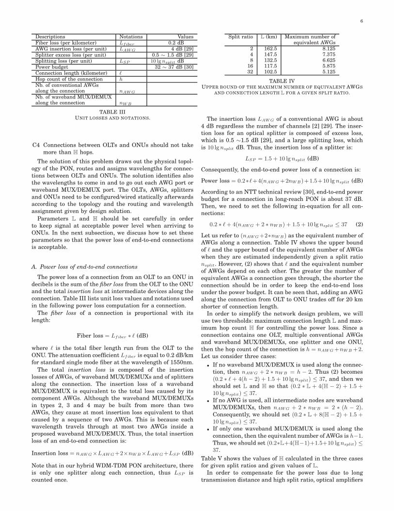
C4 Connections between OLTs and ONUs should not takemore than H hops.
The solution of this problem draws out the physical topol-ogy of the PON, routes and assigns wavelengths for connec-tions between OLTs and ONUs. The solution identifies alsothe wavelengths to come in and to go out each AWG port orwaveband MUX/DEMUX port. The OLTs, AWGs, splittersand ONUs need to be configured/wired statically afterwardsaccording to the topology and the routing and wavelengthassignment given by design solution.
Parameters L and H should be set carefully in orderto keep signal at acceptable power level when arriving toONUs. In the next subsection, we discuss how to set theseparameters so that the power loss of end-to-end connectionsis acceptable.
A. Power loss of end-to-end connections
The power loss of a connection from an OLT to an ONU indecibels is the sum of the fiber loss from the OLT to the ONUand the total insertion loss at intermediate devices along theconnection. Table III lists unit loss values and notations usedin the following power loss computation for a connection.
The fiber loss of a connection is proportional with itslength:
Fiber loss = Lfiber ∗ ℓ (dB)
where ℓ is the total fiber length run from the OLT to theONU. The attenuation coefficient Lfiber is equal to 0.2 dB/kmfor standard single mode fiber at the wavelength of 1550nm.
The total insertion loss is composed of the insertionlosses of AWGs, of waveband MUX/DEMUXs and of splittersalong the connection. The insertion loss of a wavebandMUX/DEMUX is equivalent to the total loss caused by itscomponent AWGs. Although the waveband MUX/DEMUXsin types 2, 3 and 4 may be built from more than twoAWGs, they cause at most insertion loss equivalent to thatcaused by a sequence of two AWGs. This is because eachwavelength travels through at most two AWGs inside aproposed waveband MUX/DEMUX. Thus, the total insertionloss of an end-to-end connection is:
Insertion loss = nAWG×LAWG+2×nWB×LAWG+LSP (dB)
Note that in our hybrid WDM-TDM PON architecture, thereis only one splitter along each connection, thus LSP iscounted once.
Split ratio L (km) Maximum number ofequivalent AWGs
2 162.5 8.1254 147.5 7.3758 132.5 6.625
16 117.5 5.87532 102.5 5.125
TABLE IVUPPER BOUND OF THE MAXIMUM NUMBER OF EQUIVALENT AWGS
AND CONNECTION LENGTH L FOR A GIVEN SPLIT RATIO.
The insertion loss LAWG of a conventional AWG is about4 dB regardless the number of channels [2] [29]. The inser-tion loss for an optical splitter is composed of excess loss,which is 0.5 ∼1.5 dB [29], and a large splitting loss, whichis 10 lgnsplit dB. Thus, the insertion loss of a splitter is:
LSP = 1.5 + 10 lgnsplit (dB)
Consequently, the end-to-end power loss of a connection is:
Power loss = 0.2∗ℓ+4(nAWG +2nWB)+1.5+10 lg nsplit (dB)
According to an NTT technical review [30], end-to-end powerbudget for a connection in long-reach PON is about 37 dB.Then, we need to set the following in-equation for all con-nections:
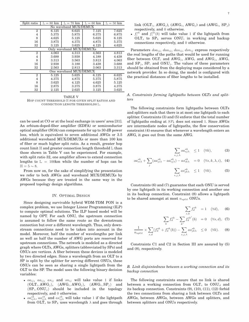
Let us refer to (nAWG+2∗nWB) as the equivalent number ofAWGs along a connection. Table IV shows the upper boundof ℓ and the upper bound of the equivalent number of AWGswhen they are estimated independently given a split rationsplit. However, (2) shows that ℓ and the equivalent numberof AWGs depend on each other. The greater the number ofequivalent AWGs a connection goes through, the shorter theconnection should be in order to keep the end-to-end lossunder the power budget. It can be seen that, adding an AWGalong the connection from OLT to ONU trades off for 20 kmshorter of connection length.
In order to simplify the network design problem, we willuse two thresholds: maximum connection length L and max-imum hop count H for controlling the power loss. Since aconnection contains one OLT, multiple conventional AWGsand waveband MUX/DEMUXs, one splitter and one ONU,then the hop count of the connection is h = nAWG+nWB +2.Let us consider three cases:
• If no waveband MUX/DEMUX is used along the connec-tion, then nAWG + 2 ∗ nWB = h − 2. Thus (2) becomes(0.2 ∗ ℓ + 4(h − 2) + 1.5 + 10 lgnsplit) ≤ 37, and then weshould set L and H so that (0.2 ∗ L + 4(H − 2) + 1.5 +10 lgnsplit) ≤ 37.
• If no AWG is used, all intermediate nodes are wavebandMUX/DEMUXs, then nAWG + 2 ∗ nWB = 2 ∗ (h − 2).Consequently, we should set (0.2 ∗ L + 8(H − 2) + 1.5 +10 lgnsplit) ≤ 37.
• If only one waveband MUX/DEMUX is used along theconnection, then the equivalent number of AWGs is h−1.Thus, we should set (0.2∗L+4(H−1)+1.5+10 lgnsplit) ≤37.
Table V shows the values of H calculated in the three casesfor given split ratios and given values of L.
In order to compensate for the power loss due to longtransmission distance and high split ratio, optical amplifiers
7
Split ratio L = 80 km L = 70 km L = 60 km L = 50 kmNo waveband MUX/DEMUX
TABLE VHOP COUNT THRESHOLD H FOR GIVEN SPLIT RATIOS AND
CONNECTION LENGTH THRESHOLDS L.
can be used at CO or at the local exchange in users’ area [31].An erbium-doped-fiber amplifier (EDFA) or semiconductoroptical amplifier (SOA) can compensate for up to 30 dB powerloss, which is equivalent to seven additional AWGs or 3.5additional waveband MUX/DEMUXs or more than 100 kmof fiber or much higher split ratio. As a result, greater hopcount limit H and greater connection length threshold L thanthose shown in Table V can be experienced. For example,with split ratio 32, one amplifier allows to extend connectionlengths to L = 100km while the number of hops can beH = 5 ∼ 8.
From now on, for the sake of simplifying the presentationwe refer to both AWGs and waveband MUX/DEMUXs byAWGs because they are treated in the same way in theproposed topology design algorithms.
IV. OPTIMAL DESIGN
Since designing survivable hybrid WDM-TDM PON is acomplex problem, we use Integer Linear Programming (ILP)to compute optimal solutions. The ILP based model will benamed by OPT. For each ONU, the upstream connectionis assumed to follow the same route as the downstreamconnection but over a different wavelength. Thus, only down-stream connections need to be taken into account in themodel. Moreover, half the number of wavelengths per linkas well as half the number of AWG ports are reserved forupstream connections. The network is modeled as a directedgraph where OLTs, AWGs, splitters (abbreviated by SPs) andONUs are vertices. A fiber between these devices is modeledby two directed edges. Since a wavelength from an OLT to aSP is split by the splitter for serving different ONUs, theseONUs can be seen as sharing a single lightpath from theOLT to the SP. The model uses the following binary decisionvariables:
• oaij , aaij , asij and snij will take value 1 if links(OLTi, AWGj), (AWGi, AWGj), (AWGi, SPj) and(SPi, ONUj) should be included in the topologyrespectively, and 0 otherwise.
• oaskijλ, aask
ijλ and asskijλ will take value 1 if the lightpathfrom OLTs to SPk uses wavelength λ and goes through
link (OLTi, AWGj), (AWGi, AWGj ) and (AWGi, SPj)respectively, and 0 otherwise.
• fski and fsk
i (b) will take value 1 if the lightpath fromOLTs to SPk serves ONUi in working and backupconnections respectively, and 0 otherwise.
Parameters doaij , daaij , dasij , dsnij express respectivelythe real lengths of the paths that would be used for runningfiber between OLTi and AWGj , AWGi and AWGj , AWGi
and SPj , SPi and ONUj . The values of these parametersshould be obtained from the deploying maps considered by anetwork provider. In so doing, the model is configured withthe practical distances of fiber lengths to be installed.
A. Constraints forming lightpaths between OLTs and split-
ters
The following constraints form lightpaths between OLTsand splitters such that there is at most one lightpath to eachsplitter. Constraints (3) and (5) enforce that the total numberof lightpaths ending at SPk does not exceed 1. Since AWGsare intermediate nodes of lightpaths, the flow conservationconstraint (4) ensures that whenever a wavelength enters anAWG, it goes out from the same AWG.
∑
s,j,λ
oasksjλ ≤ 1 (∀k), (3)
oasksiλ +
∑
j
(aaskjiλ − aask
ijλ)− asskikλ = 0 (∀s, k, λ, i), (4)
∑
s,j,λ
asskjkλ ≤ 1 (∀k). (5)
Constraints (6) and (7) guarantee that each ONU is servedby one lightpath in its working connection and another onein its backup connection. Constraint (8) allows a lightpathto be shared amongst at most nsplit ONUs.
∑
s,k
fskd = 1 (∀d), (6)
∑
k
fskd −
∑
k′
fsk′
d (b) = 0 (∀s, d), (7)
1
nsplit
×∑
s,d
(fskd + fsk
d (b))−∑
s,j,λ
asskjkλ ≤ 0 (∀k). (8)
Constraints C1 and C2 in Section III are assured by (5)and (8), respectively.
B. Link disjointedness between a working connection and its
backup connection
The following constraints ensure that no link is sharedbetween a working connection from OLTs to ONUd andits backup connection. Constraints (9), (10), (11), (12) forbidthe two connections from sharing a link between OLTs andAWGs, between AWGs, between AWGs and splitters, andbetween splitters and ONUs respectively.
8
∑
λ
(oasksjλ + oask′
sjλ) + fskd + fsk′
d (b) ≤ 3,
(∀s, d, k 6= k′, j) (9)∑
λ
(aaskijλ + aask′
ijλ + aask′
jiλ) + fskd + fsk′
d (b) ≤ 3,
(∀s, d, k 6= k′, i, j) (10)∑
λ
(asskikλ + assk′
ik′λ) + fskd + fsk′
d (b) ≤ 3,
(∀s, d, k 6= k′, i) (11)
fskd + fsk
d (b) ≤ 1(∀s, d, k). (12)
C. Constraints verifying if a link should be included in the
topology
Constraints (13), (14), (15), (16) ensure that: if there is aconnection going through a link between OLTs and AWGs, orbetween AWGs, or between AWGs and splitters, or betweensplitters and ONUs, these links must be included in the PONtopology:
∑
s,k,λ
oasksjλ ≤ Z.oasj , ∀(s, j), (13)
∑
s,k,λ
aaskijλ ≤ Z.aaij , ∀(i, j), (14)
∑
s,λ
asskikλ ≤ Z.asik, ∀(i, k), (15)
∑
s
(fskd + fsk
d (b)) ≤ Z.snkd, ∀(k, d), (16)
Z is a sufficiently large constant such that whenever asum on the left-hand side of an inequality is positive, theinequality will hold if the right-hand side variable is set to1. For example, Z can be the product of the number of OLTs,the number of ONUs in the network and W/2.
D. Wavelength unity constraints
Since a lightpath takes entirely a wavelength, there shouldbe at most one lightpath using a given wavelength on a fiberlink. Constraints (17), (18), (19) ensure that this requirementis satisfied on links between OLT and AWG, AWG andsplitter, splitter and ONU respectively.
∑
k
oasksjλ ≤ 1 (∀s, j, λ), (17)
∑
s,k
(aaskijλ + aask
jiλ) ≤ 1 (∀i, j, λ), (18)
∑
s
asskikλ ≤ 1 (∀i, k, λ). (19)
E. Constraints on the number of ports of AWGs
Each AWG has N × N ports. Since half the number ofports of each AWG is reserved for the upstream, the numberof incoming ports and outgoing ports of AWGs must berestricted to N/2.
∑
i
oaij +∑
i
aaij ≤ N/2 (∀j) (20)
∑
j
aaij +∑
j
asij ≤ N/2 (∀i) (21)
F. Constraint on the number of ports of OLTs
The total number of links from an OLT must not be greaterthan the number of ports n0 of each OLT.
∑
j
oaij ≤ n0 (∀i) (22)
G. Constraints on hop count
In order to reduce power loss, every connection must belimited by H hops (constraint C4 in Section III). The firsthop is from an OLT to the first AWG, the last two hops arefrom the last AWG to a splitter and then an ONU. Therefore,the number of remaining hops between the first and the lastAWG should not exceed (H − 3). The following constraintlimits the number of hops for the working connections. Asimilar constraint should be applied as well to the backupconnections.
∑
i,j,λ
aaskijλ ≤ H − 3, (∀s, k). (23)
H. Distance constraints
Again, in order to reduce power loss, the lengths of workingand backup connections must be limited by L (constraint C3in Section III). The following constraint is for the workingconnections. Backup connections need similar constraints.
∑
j,λ
oasksjλ × doasj +
∑
i,j,λ
aaskijλ × daaij +
∑
i,λ
asskikλ × dasik
+ fskd × dsnkd ≤ L, (∀s, k, d). (24)
I. Objective function
The objective of topology design is to minimize the totallength of fiber. It can be expressed by:
minimize∑
i,j
oaij × doaij +∑
i,j
aaij × aaji × daaij+
∑
i,j
asij × dasij +∑
i,j
snij × dsnij . (25)
Note that the product aaij × aaji can be easily linearized byusing supplementary binary variables.
The ILP model of OPT provides optimal solutions but themodel size grows up quickly when the number of networkequipment, number of wavelengths over a fiber W and split-ting ratio nsplit increase. The model can actually run forsmall size networks. To solve the design problem for largersize networks, we will propose two heuristics in the followingsections.
V. STAR DESIGN
In this section we propose a heuristic for designing asurvivable hybrid WDM-TDM PON without considering thelinks between AWGs. The network has a star structureexcept that each ONU connects to two splitters in order to bereachable by an OLT through two link-disjoint paths for sur-vivable purpose. A path is taken by the working connectionand the other is for the backup connection. The algorithmexamines different combinations of ONUs, splitters, AWGsand OLT for choosing the best one according to followingsteps:
1) For each pair of splitters SPx,SPy :
9
a. Find the two best AWGi,AWGj and an OLTu sothat the total fiber length running along OLTu-AWGi-SPx and along OLTu-AWGj-SPy is minimal.These paths have to satisfy constraints on wave-lengths, hop count and fiber length. Let us denotethe total fiber length by δ1.
b. Select a group of nsplit ONUs that has the smallesttotal distance to the two splitters. Let us denote thetotal distance by δ2.
2) Select the pair of splitters that minimizes the sumδ1 + δ2. Connect the splitters with the two AWGs, theOLT and the nsplit ONUs that made the minimumδ1 + δ2 while checking the wavelength availability andport availability. Remove the selected splitters andONUs from the list of devices to be considered in thenext rounds.
3) Repeat Step 1 and 2 with the remaining splitters andONUs until there is no more ONU to be considered.
Fig. 9a illustrates a combination of OLT, AWGs, splittersand ONUs that is selected by the algorithm. Fig. 9b showsthe result of the algorithm.
(a) (b)
Fig. 9. Illustration of star design.
VI. MESH DESIGN
In this section, we propose a more efficient heuristic al-gorithm called MeshLIP, which designs a true mesh WDM-TDM PON by using the links between AWGs when it isnecessary. The major advantage of MeshLIP is its polynomialrunning time, thus it can be used to design large size PONs.MeshLIP starts from a feasible network topology and thenimproves it by local improvement procedures. The algorithmis as flows:
• [Initial solution calculation phase] An initial so-lution can be any feasible solution that satisfies allthe problem constraints. Star design can be used forgenerating an initial solution.
• [Local improvement phase] The initial solution isimproved by changing the linkages between devices insuch a way that the total fiber length is reduced.
We propose 5 following local improvements. These im-provements are applied successively, each one improves alittle bit the topology.
1) [Switch ONUs to available SPs]: for each pair ofavailable SPs, change some ONUs to connect to theseSPs if that leads to a reduction of the total fiber length.See Algorithm 1 for more details and Fig. 10 for anillustration.
2) [Switch between current ONU-SP links]: for eachpair of links ONUx1
-SPy1 and ONUx2-SPy2 , permute
the linkages to obtain the pair ONUx1-SPy2 and
ONUx2-SPy1 if that leads to a reduction of the total
fiber length. See Algorithm 2 for more details andFig. 11 for an illustration.
3) [Switch between current SP-AWG links]: for eachpair of links SPx1
-AWGy1 and SPx2-AWGy2 , permute
the linkages to obtain the pair SPx1-AWGy2 and SPx2
-AWGy1 if that leads to a reduction of the total fiberlength. See more details in Algorithm 3 and Fig. 12 foran illustration.
4) [Switch SPs to available AWGs]: for each SP, findan alternative AWG to link with, if that leads to a re-duction of the fiber length. In this case, when possible,the algorithm uses the short direct connection betweenthe alternative AWG and in-use AWGs to prevent es-tablishing new long OLT-AWG links. See Algorithm 4for more details and Fig. 13 for an illustration.
5) [Switch AWG-OLT links to AWG-AWG-OLT links]:Change an AWG from directly linking with an OLT toindirectly connecting with the same OLT through anintermediate AWG, if that leads to a reduction of thefiber length. The two AWGs must not link to splittersthat link to common ONUs. Otherwise, the workingand backup connections of these ONUs will not be link-disjoint. See Algorithm 5 for more details and Fig. 14for an illustration.
In all improvement procedures, all problem constraints arealways checked at appropriate steps.
(a) Before (b) After
Fig. 10. Illustration of Improvement 1.
(a) Before (b) After
Fig. 11. Illustration of Improvement 2.
VII. NUMERICAL RESULTS
The proposed PON design algorithms have been imple-mented. OPT is implemented using ILOG CPLEX Academicedition [32]. Heuristics Star and MeshLIP are implementedin C. The algorithms are tested with different network
10
Algorithm 1: IMPROVEMENT 1
input : current topologyoutput: new improvement if δmax > 0
Min2Paths(SPx,SPy): finds OLTz which minimizes twolink disjoint paths from it to SPx and SPy and returns thisminimal value;
MaxONUs(SPx,SPy): finds a group of maximum nsplit ONUswhich maximizes the amount of cable length saving ifswitching these ONUs to SPx,SPy ;
Max(α, β): returns α if α > β and returns β otherwise;———————–
6 if δmax > 0 then7 Determine nsplit ONUs and the free pair SPs leading to
δmax, then switch current links of these ONUs to thispair SPs and link these SPs to the corresponding OLT;
Algorithm 2: IMPROVEMENT 2
input : current topologyoutput: new improvement for each δ > 0
Distance(A,B): returns the cable length linking device A
to device B;———————–
1 foreach pair (ONUx1,ONUx2
) do2 SPy1 ← a current link to ONUx1
;3 SPy2 ← a current link to ONUx2
;4 δ =
(Distance(ONUx1,SPy1) + Distance(ONUx2
,SPy2))−(Distance(ONUx2
,SPy1) + Distance(ONUx1,SPy2));
5 if δ > 0 then6 Remove links: ONUx1
→ SPy1 , ONUx2→ SPy2 ;
7 Connect links: ONUx1→ SPy2 , ONUx2
→ SPy1 ;
Algorithm 3: IMPROVEMENT 3
input : current topologyoutput: new improvement for each δ > 0
———————–1 foreach pair (SPx1
,SPx2) do
2 AWGy1 ← a current link to SPx1;
3 AWGy2 ← a current link to SPx2;
4 δ =(Distance(SPx1
,AWGy1 ) + Distance(SPx2,AWGy2))−
(Distance(SPx2,AWGy1 ) + Distance(SPx1
,AWGy2));5 if δ > 0 then6 Remove links: SPx1
→ AWGy1 , SPx2→ AWGy2 ;
7 Connect links: SPx1→ AWGy2 , SPx2
→ AWGy1 ;
(a) Before (b) After
Fig. 12. Illustration of Improvement 3.
(a) Before (b) After
Fig. 13. Illustration of Improvement 4.
instances in order to evaluate their performances as well asto prove the advantages of the mesh topology for long-reachhybrid WDM-TDM PON.
Each network instance is characterized by the coordinatesof PON devices (i.e. OLTs, AWGs, SPs and ONUs) in a2D plan and parameters W, L, H, nsplit, N. It is generallyexpected that connections of long-reach PON go up to 100km,then L is set to 100km. A connection in the proposed mesharchitecture can go zigzag through multiple AWGs, thusthe distance between an OLT and a service area should bearound 80 km. Consequently, the coordinates of OLTs aregenerated so that the OLTs are in about 80 km from thecenter of service areas. Since in LR-PON, the service areasize is much smaller than its distance to the Central Office,we limit the service area diameter in 6km. According to the
Algorithm 4: IMPROVEMENT 4
input : current topologyoutput: new improvement if δmax > 0
9 if δmax > 0 then10 Determine in-use AWGx, free AWGy and SPs leading to
δmax, then Switch current links of these SPs to AWGy
and Connect AWGx to AWGy;
11
(a) Before (b) After
Fig. 14. Illustration of Improvement 5.
Algorithm 5: IMPROVEMENT 5
input : current topologyoutput: new improvement if δmax > 0
———————–1 δmax = 0;2 foreach OLTz do3 foreach in-use pair (AWGx,AWGy) linking to OLTz do4 if
Distance(AWGx,OLTz) > Distance(AWGy ,OLTz)then
5 Exchange the role of x and y;
6 δ =Distance(AWGx,OLTz)−Distance(AWGx,AWGy);
7 δmax = Max(δmax, δ);
8 if δmax > 0 then9 Determine pair AWGx,AWGy,OLTz leading to δmax,
then Remove link AWGx → OLTz and Connect AWGx toAWGy;
computation in Section III, with no more than one amplifieralong a connection, when L = 100, the split ratio nsplit canbe set to 32, H can be set to 5. The AWGs, SPs and ONUsare distributed randomly in service areas. Let us denote thesize of a network instance by #OLTs-#AWGs-#SPs-#ONUs (#stands for the number of ). We generated three datasets fortesting the proposed algorithms:
• Dataset 1: 130 network instances with sizes varyingfrom 1-3-8-8 to 1-7-24-24, W = 16, number of ports ofan AWG N = 8, nsplit = 2, L = 100 km, H = 5.
• Dataset 2: 130 network instances with sizes varyingfrom 1-3-8-16 to 1-7-24-48, W = 16, N = 8, nsplit = 4,L = 100 km, H = 5.
• Dataset 3: 1430 network instances with sizes varyingfrom 1-8-48-624 to 1-10-74-1184, W = 32, N = 16,nsplit = 32, L = 100 km, H = 5.
Although the proposed algorithms are ready for multipleOLTs, we currently test with single OLT networks. Testswith more OLTs are unnecessary since different OLTs areusually asked to serve different service areas.
Star and MeshLIP provide design results instantly foreach network instance. OPT takes times varying from sev-eral seconds to several hours for each network in Datasets 1and 2; and even cannot terminate for a network of Dataset 3.Fig. 15 presents an example of a PON, where OLT is at point(0, 0) and other devices are in the remote service area.
0
54000
57000
60000
0 54000 57000 60000
me
tte
rs
metters
service area
link OLT-AWG
link AWG-AWG
link AWG-SP
link SP-ONU
Fig. 15. Example of a survivable long-reach hybrid WDM-TDMPON designed by Local-Search. Links between OLT and AWGs aredash black lines, between AWGs are blue thickest lines, betweenAWGs and SPs are red medium lines, between SPs and ONUs aregreen thin lines.
A. Gaps between Star, MeshLIP and OPT
We evaluate the performance of the proposed algorithmsby making comparison between the total fiber lengths thatStar, MeshLIP and OPT propose for each network instancein the three datasets. Due to the high computational effortof OPT, the tests can be performed only on networks withsizes up to 1-5-14-14 of Dataset 1 and sizes up to 1-4-14-28of Dataset 2. Two versions of MeshLIP have been tested:
• MeshLIP Impr. 1-2-3: In this version, only improve-ments 1, 2 and 3 are applied subsequently in this orderduring the local improvement procedure. Each improve-ment is performed once.
• MeshLIP Impr. 1-2-3-4-5: In this version, all improve-ments are applied subsequently in this order. Eachimprovement is performed once. Note that the improve-ments 4 and 5 consider the use of links between AWGswhile the others do not.
We have also tried to repeat the five improvements morethan once in order to see if they could improve furtherthe design. We have remarked that the next round of five-improvement provides usually the same results with the pre-vious one. This phenomenon reveals that MeshLIP convergesusually right after the first round of five-improvement.
Table VI shows the average relative gaps between thetotal fiber lengths given by the proposed heuristics and thosegiven by OPT for the same network instances. The gapbetween a solution of an algorithm X and OPT is computedas:
fiber length in X − fiber length in OPT
fiber length in OPT, (26)
where fiber lengths are the total lengths of fiber to be usedin the topologies designed by algorithm X and by OPT.
Star and MeshLIP Impr. 1-2-3 do not use links betweenAWGs in their designs. Although MeshLIP provides bettergaps than Star when Improvements 1, 2 and 3 are used,it provides even much smaller gaps when Improvements 4and 5 are added. This is explained by the fact that Improve-ments 4 and 5 use links between AWGs, which leads to the
12
Star MeshLIP MeshLIP(%) Impr. 1-2-3 (%) Impr. 1-2-3-4-5 (%)
TABLE VIIAVERAGE RELATIVE GAPS BETWEEN MESHLIP AND STAR.
reduction of the total fiber length. Consequently, the optimalsolutions are approached.
For comparing MeshLIP with Star only, we have run alltest cases of the three datasets. Then, we compute the rela-tive gaps between them according to the following formula:
fiber length in X − fiber length in Star
fiber length in Star(27)
Table VII shows the relative gaps of MeshLIP over Star.The negative gaps indicate that MeshLIP saves more fiberthan Star in average. The gaps in Table VII shows that Staris improved approximately from 12% to 15% by performingImprovements 1-2-3, and is about twice greater improvedwhen links between AWGs are allowed by adding Improve-ments 4-5 afterwards (here we refer to the gaps between19.75 % and 30.74%) .
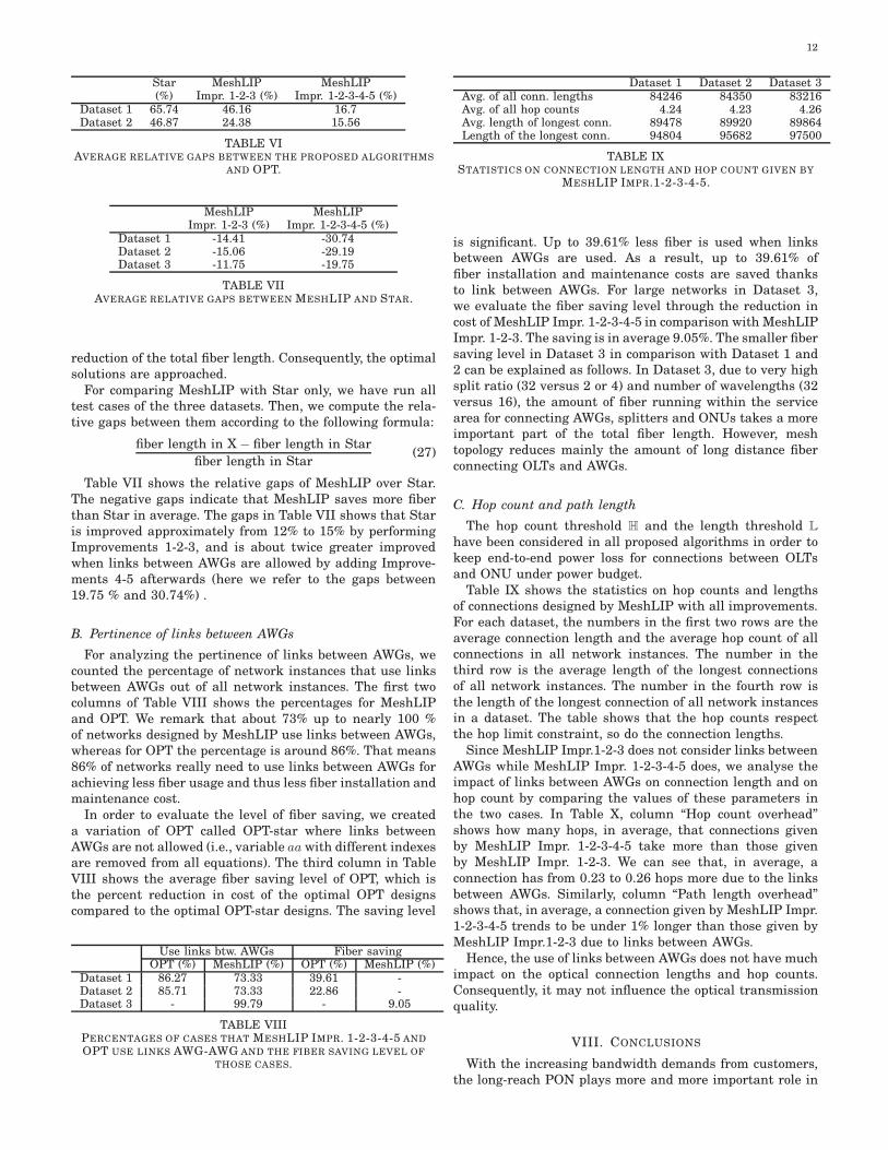
B. Pertinence of links between AWGs
For analyzing the pertinence of links between AWGs, wecounted the percentage of network instances that use linksbetween AWGs out of all network instances. The first twocolumns of Table VIII shows the percentages for MeshLIPand OPT. We remark that about 73% up to nearly 100 %of networks designed by MeshLIP use links between AWGs,whereas for OPT the percentage is around 86%. That means86% of networks really need to use links between AWGs forachieving less fiber usage and thus less fiber installation andmaintenance cost.
In order to evaluate the level of fiber saving, we createda variation of OPT called OPT-star where links betweenAWGs are not allowed (i.e., variable aa with different indexesare removed from all equations). The third column in TableVIII shows the average fiber saving level of OPT, which isthe percent reduction in cost of the optimal OPT designscompared to the optimal OPT-star designs. The saving level
TABLE VIIIPERCENTAGES OF CASES THAT MESHLIP IMPR. 1-2-3-4-5 AND
OPT USE LINKS AWG-AWG AND THE FIBER SAVING LEVEL OF
THOSE CASES.
Dataset 1 Dataset 2 Dataset 3Avg. of all conn. lengths 84246 84350 83216Avg. of all hop counts 4.24 4.23 4.26Avg. length of longest conn. 89478 89920 89864Length of the longest conn. 94804 95682 97500
TABLE IXSTATISTICS ON CONNECTION LENGTH AND HOP COUNT GIVEN BY
MESHLIP IMPR.1-2-3-4-5.
is significant. Up to 39.61% less fiber is used when linksbetween AWGs are used. As a result, up to 39.61% offiber installation and maintenance costs are saved thanksto link between AWGs. For large networks in Dataset 3,we evaluate the fiber saving level through the reduction incost of MeshLIP Impr. 1-2-3-4-5 in comparison with MeshLIPImpr. 1-2-3. The saving is in average 9.05%. The smaller fibersaving level in Dataset 3 in comparison with Dataset 1 and2 can be explained as follows. In Dataset 3, due to very highsplit ratio (32 versus 2 or 4) and number of wavelengths (32versus 16), the amount of fiber running within the servicearea for connecting AWGs, splitters and ONUs takes a moreimportant part of the total fiber length. However, meshtopology reduces mainly the amount of long distance fiberconnecting OLTs and AWGs.
C. Hop count and path length
The hop count threshold H and the length threshold L
have been considered in all proposed algorithms in order tokeep end-to-end power loss for connections between OLTsand ONU under power budget.
Table IX shows the statistics on hop counts and lengthsof connections designed by MeshLIP with all improvements.For each dataset, the numbers in the first two rows are theaverage connection length and the average hop count of allconnections in all network instances. The number in thethird row is the average length of the longest connectionsof all network instances. The number in the fourth row isthe length of the longest connection of all network instancesin a dataset. The table shows that the hop counts respectthe hop limit constraint, so do the connection lengths.
Since MeshLIP Impr.1-2-3 does not consider links betweenAWGs while MeshLIP Impr. 1-2-3-4-5 does, we analyse theimpact of links between AWGs on connection length and onhop count by comparing the values of these parameters inthe two cases. In Table X, column “Hop count overhead”shows how many hops, in average, that connections givenby MeshLIP Impr. 1-2-3-4-5 take more than those givenby MeshLIP Impr. 1-2-3. We can see that, in average, aconnection has from 0.23 to 0.26 hops more due to the linksbetween AWGs. Similarly, column “Path length overhead”shows that, in average, a connection given by MeshLIP Impr.1-2-3-4-5 trends to be under 1% longer than those given byMeshLIP Impr.1-2-3 due to links between AWGs.
Hence, the use of links between AWGs does not have muchimpact on the optical connection lengths and hop counts.Consequently, it may not influence the optical transmissionquality.
VIII. CONCLUSIONS
With the increasing bandwidth demands from customers,the long-reach PON plays more and more important role in
TABLE XHOP COUNT AND PATH LENGTH OVERHEADS DUE TO THE USE OF
LINKS BETWEEN AWGS IN MESHLIP 1-2-3-4-5
access network deployment. In this paper, we have shownthat the use of the hybrid WDM-TDM PON architecturewith mesh links between AWGs in service areas is feasiblewhen using the proposed Waveband MUX/DEMUXs. More-over, the use of mesh links between AWGs helps reducethe fiber installation and maintenance costs of long-reachaccess networks since it allows to avoid unnecessary longfiber between CO and service areas. We have also developedefficient heuristic algorithms for designing the topology ofthe PON following this architecture such that all connectionsbetween OLTs and ONUs are survivable upon any singlefailure. According to the experiments, about 86% of optimalnetwork topologies should use links between AWGs. Theexperimental results also show that the heuristic algorithmsfind solutions very close to optimal ones.
ACKNOWLEDGEMENTS
The work of the first author is supported by Vietnam’sNational Foundation for Science and Technology Develop-ment (NAFOSTED) under the grant number 102.01.13.09.The authors would like also to thank Dr. Ngoc T. Dang fromthe Post and Telecommunications Institute of Technologyof Vietnam for his fruitful discussions and comments forthe paper and Quang Huy Duong from Hanoi University ofScience and Technology for his implementation of MeshLIP.
REFERENCES
[1] C. Bock, J. Prat, and S. Walker, “Hybrid WDM/TDM PON usingthe AWG FSR and featuring centralized light generation anddynamic bandwidth allocation,” Journal of Lightwave Technol-ogy, pp. 3981 – 3988, Dec 2005.
[2] H. Venghaus, Ed., Wavelength Filters in Fibre Optics, ser.Springer Series in Optical Sciences. Springer, 2010.
[3] G. Talli and P. D. Townsend, “Hybrid DWDM - TDM Long-Reach PON for Next-Generation Optical Access,” Journal ofLightwave Technology, vol. 24, no. 7, pp. 2827–2834, July 2006.
[4] D. Shea and J. Mitchell, “Long-reach optical access technolo-gies,” IEEE Network, vol. 21, no. 5, pp. 5–11, 2007.
[5] F.-T. An, K. S. Kim, D. Gutierrez, S. Yam, E. S.-T. Hu, andF. I. F. Osa, “SUCCESS: A Next-Generation Hybrid WDM/TDMOptical Access Network Architecture,” Journal of LightwaveTechnology, vol. 22, no. 11, pp. 2557–2569, 2004.
[6] A. Gumaste, D. Diwakar, A. Agrawal, A. Lodha, and N. Ghani,“Light-mesh - a pragmatic optical access network architecturefor ip-centric service oriented communication,” Optical Switch-ing and Networking, vol. 5, no. 2-3, pp. 63–74, 2008.
[7] D.-L. Truong and A. T. Pham, “A model for designing survivablemesh optical access networks,” in International Conference onAdvanced Technologies for Communications (ATC), Aug 2011,pp. 156–160.
[8] C. Dragone, “An N*N optical multiplexer using a planar ar-rangement of two star couplers,” IEEE Photonics TechnologyLetters, vol. 3, no. 9, pp. 812–815, 1991.
[9] S. Kakehashi, H. Hasegawa, K. Sato, O. Moriwaki, S. Kamei,Y. Jinnouchi, and M. Okuno, “Performance of WavebandMUX/DEMUX Using Concatenated AWGs,” IEEE PhotonicsTechnology Letters, vol. 19, no. 16, pp. 1197 – 1199, Aug. 2007.
[10] S. Kakehashi, H. Hasegawa, K. ichi Sato, O. Moriwaki, andS. Kamei, “Analysis and development of fixed and variablewaveband mux/demux utilizing awg routing functions,” Journalof Lightwave Technology, vol. 27, no. 1, pp. 30–40, Jan 2009.
[11] M. Ruffini, D. Mehta, B. O’Sullivan, L. Quesada, L. Doyle, andD. B. Payne, “Deployment Strategies for Protected Long-ReachPON,” Journal of Optical Communication Networking, vol. 4,no. 2, pp. 118–129, Feb 2012.
[12] U.S. Department of Transportation Research and InnovativeTechnology Administration, “Its unit costs database,” Oct. 2010.
[13] ——, “Intelligent Transportation Systems Benefits, Costs, De-ployment, and Lessons Learned: 2011 Update,” Oct. 2010.
[14] J. Li and G. Shen, “Cost Minimization Planning for GreenfieldPassive Optical Networks,” Journal of Optical CommunicationNetworking, vol. 1, pp. 17–29, 2009.
[15] “AliExpress website,” http://www.aliexpress.com, 2013.[16] G. Maier, M. Martinelli, A. Pattavina, and E. Salvadori, “Design
and cost performance of the multistage WDM-PON accessnetworks,” Journal of Lightwave Technology, vol. 18, no. 2, pp.125–143, 2000.
[17] J. Zhang and B. Mukherjee, “A review of Fault Managementin WDM Mesh networks: Basic Concept and Research Chal-lenges,” IEEE Network, vol. 18, no. 2, pp. 41–48, Mar. 2004.
[18] D.-L. Truong and B. Jaumard, “Recent progress in dynamicrouting for shared protection in multidomain networks,” Com-munications Magazine, IEEE, vol. 46, no. 6, pp. 112–119, 2008.
[19] H. Luu and F. Tobagi, “Physical topology design for all-opticalnetworks,” in International Conference on Broadband Commu-nications, Networks and Systems (BROADNETS), Oct. 2006,pp. 1–10.
[20] Y. Xin, G. Rouskas, and H. Perros, “On the physical and logicaltopology design of large-scale optical networks,” Journal ofLightwave Technology, vol. 21, no. 4, pp. 904 – 915, 2003.
[21] R. M. Krishnaswamy and K. N. Sivarajan, “Design of logicaltopologies: a linear formulation for wavelength-routed opticalnetworks with no wavelength changers,” IEEE/ACM Trans.Netw., vol. 9, no. 2, pp. 186–198, 2001.
[22] B. Lakic and M. Hajduczenia, “On optimized Passive OpticalNetwork (PON) deployment,” in Second International Confer-ence on Access Networks and Workshops, Ottawa, Canada, Aug2007, pp. 1–8.
[23] A. Agata and Y. Horiuchi, “PON Network Designing Algorithmfor Suboptimal Deployment of Optical Fiber Cables,” in AsiaCommunications and Photonics Conference and Exhibition,Shanghai, China, November 2009, pp. 1–2.
[24] B. Kantarci and H. Mouftah, “Optimization models for reliablelong-reach pon deployment,” in IEEE Symposium on Computersand Communications (ISCC), July 2011, pp. 506 – 511.
[25] E. Wong and K.-L. Lee, “Automatic protection, restoration, andsurvivability of long-reach passive optical networks,” in IEEEInternational Conference on Communications (ICC), July 2011,pp. 1–6.
[26] J. Zhang and N. Ansari, “Minimizing the arrayed waveguidegrating cost and the optical cable cost in deploying wdm passiveoptical networks,” Journal of Optical Communications andNetworking, vol. 1, no. 5, pp. 352–365, 2009.
[27] B. Jaumard and R. Chowdhury, “Location and allocation ofswitching equipment (splitters/awgs) in a wdm pon network,”in Proceedings of 20th International Conference on ComputerCommunications and Networks (ICCCN), 2011, pp. 1–8.
[28] B. Glance, I. KAMINOW, and R. Wilson, “Applications of theintegrated waveguide grating router,” Lightwave Technology,Journal of, vol. 12, no. 6, pp. 957–962, 1994.
[29] A. Banerjee, Y. Park, F. Clarke, H. Song, S. Yang, G. Kramer,K. Kim, and B. Mukherjee, “Wavelength-division-multiplexedpassive optical network (WDM-PON) technologies for broad-band access: a review,” Journal of Optical Networking, vol. 4,no. 11, pp. 737–758, Nov 2005.
[30] H. Kimura, T. Matsumoto, S. Shimazu, S. Yamashita, andJ. Yamasaki, “Optical power budget enhancement technologiesfor long-reach ge-pon system,” NTT Technical Review, vol. 9,no. 10, pp. 1–5, 2011.
[31] H. Song, B. whi Kim, and B. Mukherjee, “Long-reach opticalaccess networks: A survey of research challenges, demonstra-tions, and bandwidth assignment mechanisms,” IEEE Commu-nications Surveys Tutorials, vol. 12, no. 1, pp. 112–123, 2010.
[32] IBM Academic Initiative, “ILOG CPLEX Optimization Studio,”http://www-03.ibm.com/ibm/university/academic/pub/page/ban ilog programming.
14
Dieu Linh Truong is currently working as assistant professor inthe Department of Data Communications and Computer Networks,School of Information and Communication Technology, Hanoi Uni-versity of Science and Technology, Vietnam. She received the PhDdegree from the Department of Computer Science and OperationsResearch, Universite de Montreal, Canada in 2007, the Masterdegree from Institute de la Francophonie pour l’Informatique, Viet-nam in 2001 and the Engineer degree from Hanoi University ofTechnology in 1999. Her interests include multidomain networks,optical networks and survivable network design problems.
Phan Thuan Do is currently working as assistant professor inthe Department of Computer Science, School of Information andCommunication Technology, Hanoi University of Science and Tech-nology. He received the PhD degree from the University of Burgundy,France in 2008, the Master degree from the University of Paris 7,France in 2005 and the Engineer degree from Hanoi University of
Technology in 2003. His interests include algorithms, combinatoricsand survivable network design problems.
Anh T. Pham received the B.E. and M.E. degrees, both in Electron-ics Engineering from the Hanoi University of Science and Technol-ogy, Vietnam in 1997 and 2000, respectively, and the PhD degree inInformation and Mathematical Sciences from Saitama University,Japan in 2005. From 1998 to 2002, he was with the NTT Corp.in Vietnam. Since April 2005, he has been on the faculty at theUniversity of Aizu, where he is currently a senior associate pro-fessor at the Computer Communications Laboratory, the School ofComputer Science and Engineering. His present research interestsare in the broad areas of communication theory and networkingwith a particular emphasis on modeling, design and performanceevaluation of wired/wireless communication systems and networks.Dr. Pham is senior member of IEEE. He is also member of IEICEand OSA.