Wei et al. EURASIP Journal on Wireless Communicationsand Networking (2015) 2015:31 DOI 10.1186/s13638-015-0264-y
RESEARCH Open Access
On the polar code for the 60-GHz millimeter-wavesystemsZhuangkun Wei*, Bin Li* and Chenglin Zhao
Abstract
Given the high operating frequency band and high emission power, 60-GHz millimeter radars or communications willsuffer seriously from realistic hardware impairments. Among this, a nonlinear power amplifier (PA) will significantlydegrade its transmission performance. In this investigation, a polar code scheme originally developed by Arikan issuggested to enhance the transmission performance of 60-GHz millimeter communications. Considering the realisticdifficulties remained in calculating the Bhattacharyya parameters and likelihood ratios, unfortunately, the classical polar
coding scheme only limited to a 2 × 2 matrix1 01 1
� �; which may lose its effect when flexibly applying other l × l
matrix instead. To deal with this major challenge in flexibly applying polar code, polarization feature, a methodto seek out a matrix on which can be based, to construct polar code schemes, will be demonstrated mathematically.That is, any specified not upper triangular matrix can be used to generate a generalized polar code scheme. Secondly,two efficient recursive algorithms, i.e., recursive Z algorithm and recursive likelihood ratio algorithm, are innovativelyproposed, in order to design such a generalized polar code scheme after an l × l matrix with polarization feature isspecified. Then, the process of constructing a new polar code scheme, based on a 3 × 3 matrix, is presented to test theeffectiveness of the recursive Z algorithm and the recursive likelihood ratio algorithm. Experimental simulationsthat show a significant promotion on bit error ratio (BER) of that new polar code scheme, and illustrate a similarperformance of BER with Arikan’s original scheme, verify a successful process of flexibly constructing a generalizedpolar code scheme, on which a more sophisticated scheme based on other l × l matrix can be rested. It is furtherdemonstrated that polar coding schemes can surpass the popular low-density parity-check (LDPC) code, especiallywhen dealing with nonlinear distortions in 60-GHz communication system, which hence provides a greater promise forpractical use.
1 IntroductionCompared with the traditional radars, a 60-GHz milli-meter-wave (mm-Wave) radar is promising to more ad-verse environmental conditions, e.g., fog, rain, and snow,which may recognize the target more accurately [1,2]. Theearlier research of 60-GHz systems is mainly focused onsome military applications, e.g., the frequency-modulatedcontinuous wave (FM-CW) radars and crash-avoidanceradars [3]. With the potential of providing high data rateof Gbps, 60-GHz mm-Wave communications have alsodrawn the world-wide attentions, which have also beenconsidered as not only a promising candidate for the
* Correspondence: [email protected]; [email protected] of Information and Communication Engineering (SICE), BeijingUniversity of Posts and Telecommunications (BUPT), Beijing 100876, China
emerging fifth-generation (5G) communications but alsoan innovative idea for radar and sonar systems [3]. Amajor advantage of 60-GHz communications over othertechniques is the enormous vacant bandwidth available atthis mm-Wave band. For instance, the USA has assigned57- to 64- [4] GHz for 60-GHz communications. Furtheradopting a large effective isotropic radiated power (EIRP),the achieved transmission rate may easily surpass IEEE802.11n or UWB [5]. In the current wireless personal areanetworks standard, e.g., IEEE 802.11ad and 802.15.3c, thesingle-carrier modulations have also been recommendedas a physical layer (PHY) solution due to its flexibility andimplementation simplicity.As a double-edge sword, both the 60-GHz radars and
commercial communications, however, also encounters
Open Access article distributed under the terms of the Creative Commonsg/licenses/by/4.0), which permits unrestricted use, distribution, and reproductionroperly credited.
Wei et al. EURASIP Journal on Wireless Communications and Networking (2015) 2015:31 Page 2 of 11
some challenges from practical hardware impairments.Due to its high operating frequencies and high emissionpower, 60-GHz millimeter communications may sufferseriously from nonlinear power amplifier (PA) [5,6],which will significantly degrade its transmission per-formance. It is well known that the coding approachmay reduce the bit error ratio (BER) even in the pres-ence of nonlinear distortions, which can be suggested asa feasible approach to combat the performance degrad-ation aroused by nonlinear PA.Since the 60-GHz communications are mainly oriented
toward high-speed transmissions, the date rate is very hugeand the frame length is therefore extremely long. This may,in practice, facilitate the designing of coding schemes, byconcentrating on improving the transmission performance.For example, in the IEEE 802.11ad standard draft, low-density parity-check (LDPC) with a length of 672 bits canbe specified in the encoding method [6]. Unfortunately,with the nonlinear PA, it is shown that even such a longLDPC code has been applied, the BER performance seemsstill to be less attractive to practical use (especially for thehigh-order modulations).In this paper, we suggest a promising coding scheme
to further promote the BER performance of 60-GHzcommunication with nonlinear PA. Firstly, an originalconstruction scheme for polar code is applied to a 60-GHz system, which however has been constrained only
to the 2 × 2 matrix: F =1 01 1
� �. Secondly, after mathem-
atically analyzing the polarization feature of any l × lmatrix, two algorithms are proposed to calculate theBhattacharyya parameters and likelihood ratios, respect-ively, the former of which are the most vital componentsfor constructing a generalized polar code scheme afteran l × l matrix with polarization feature is specified,while the latter of which are the necessary preparationfor a mature decoding method. Therefore, generalizedpolar code schemes can be created after given a specifiedl × l matrix with polarization feature. In order to testifythe validity of two algorithms, as well as to testify the
Figure 1 System model.
effectiveness of polar code schemes when combattingwith nonlinear distortion in a 60-GHz system, a newpolar code scheme based on an example 3 × 3 matrix isproposed. Experimental simulations verify firstly the twoalgorithms for constructing generalized polar codeschemes and decoding schemes, secondly the effectivenessof our new polar code scheme, which will significantlypromote the transmission performance of 60-GHz com-munications, especially in the presence of nonlinear dis-tortions aroused by the radio frequency PA. It is alsodemonstrated that, compared with the popular LDPCcode, the two polar code schemes can acquire more com-petitive BER performance, which hence provides a greaterpromise to practical use.The rest of this investigation is listed as follows. Section
2 described the system model and successive cancellation(SC) modulation schemes on 60-GHz millimeter-wavecommunications. Then, in Section 3, the basic idea ofpolar code is introduced, based on which, polarizationfeature is provided and testified through mathematicalmeans. Then come recursive Z algorithm and recursivelikelihood ratio algorithm in order to deal with twodifficulties in designing constructing and decodingschemes, for any generalized polar code specified bymatrix with a polarization feature. In addition, a generalizedpolar coding scheme is given, which not only testifies theeffectiveness of recursive Z algorithm and recursive likeli-hood ratio algorithm, but can be considered as a newly pro-posed polar code scheme designed for 60-GHz millimeter-wave communications. Experimental simulations andperformance evaluations are provided in Section 4. Thewhole investigation is finally concluded in Section 5.
2 System modelA typical schematic structure of 60-GHz millimeter-wave communication system is given by Figure 1. Thesource sink generates random binary bits, which arethen fed into a coding module where the polar codingand LDPC will be used. Then, the coded signal will passthrough a modulation module which will map them into
Wei et al. EURASIP Journal on Wireless Communications and Networking (2015) 2015:31 Page 3 of 11
baseband complex signals based on the prescribed modu-lating method (typically, high-order modulation will beused, e.g., QPSK and 16-QAM). Next, the emission signalswill be distorted by a nonlinear PA, and finally, go throughthe channel by adding complex Gaussian noise in the re-ceiver. In the receiver, the contaminated signals will bedemodulated into binary bits and get decoded.
2.1 Nonlinearity of PAAfter the modulation, signals passed through a nonlin-ear PA operating in high-frequency bands, the nonlineardistortions will occur inevitably. The bad influences ofnonlinearity may lead to the distortions of both ampli-tudes and phases in output signals [7], which may be usu-ally characterized by the amplitude-amplitude (AM-AM)model and amplitude-phase (AM-PM) model signal’samplitude, respectively. These two mathematical modelsare specified as below, i.e.:
G Að Þ ¼ gA
1þ gAAsat
� �2s� � 1
2s
ð1Þ
φ Að Þ ¼ aAq1
1þ Ab
� q2� � ð2Þ
According to the IEEE 802.11ad standard, A and G(A)represent the amplitude of input and output, respectively,the latter of which has a saturation that Asat = 0.58, whileg, the linear gain, takes its value at 4.65. Parameter s = 0.81denotes smoothness of the inflection point of distortion.In the latter expression, φ(A) denotes the distortion ofPM, and parameters a, b, q1, and q2 take value at 2560,0.114, 2.4, 2.3, respectively [6].Figure 2 shows the typical mapping curve of AM-AM
which we may note that the distortions will becomemore obvious with the increasing of input amplitudes.
2.2 Modulation schemesIn this paper, binary phase shift keying (BPSK), quadra-ture phase shift keying (QPSK), 16 quadrature amplitudemodulation (16QAM), and orthogonal frequency-divisionmultiplexing (OFDM) will be considered for modulationmethods. According to Figure 2, the distortions of PSKsignals after passing through a nonlinear power ampli-fier (NLPA) can be neutralized by tilting the coordinateaxis back, a fixed angel that equals to the distortion ofphase, since the PSK signals have the identical ampli-tudes. QAM signals can be also calibrated through amethod that proportional reduces the signal’s amplitudeinto a linear area, which can still maintain a relatively dis-tinguished constellation map for demodulating. Unfortu-nately, OFDM signals, which are extremely sensitive tononlinear distortions due to its high peak-to-average powerratio (PAPR), may have the worst effect of NLPA distortionsince the IFFT process builds an irregular set of OFDMsignals.
3 Polar code for 60-GHz communicationA polar code is a kind of GN-coset code inspired by aphenomenon called channel polarization, which canbe achieved by recursively combining with N channelW : X→Y and then splitting the combined channelsinto N channels through information theory. With thismethod, the theoretical BER of some channels approachnearly to 0, while the rest of them are close to 1. And thechannel capacities among those channels go through oppos-ite directions. Those channels whose theoretical BER are ap-proaching to 0, in other words, whose channel capacities areapproaching to 1, are defined as good channels and will beselected to transmit data since the lower the theoreticalBER means a better distribution of channel capacity.
We firstly utilize aji to denote a vector (ai,ai+1,…,aj),where i and j are natural numbers with normally i ≤ j.
Otherwise, aji is regarded as void while i > j.Define a binary-input discrete memoryless channel
(B-DMC) W : X→Y , with a fixed input set {0,1}, and anarbitrary output set, is defined as symmetric only when apermutation Π : Y→Y exists, that is, there exists a πmakes sense for W(y|0) =W(Π(y)|1) for all y∈Y.When a fixed W : X→Y is given, I(W) is defined as
the mutual information between the input and output ofW : X→Y . I(W) has a spectrum of [0,1], and only wheninputs have uniform distribution, I(W) can be consideredas the capacity of channel with an expression below:
I Wð Þ ¼Xy∈Y
Xx∈X
12W yjxð Þ log W yjxð Þ
12W yj0ð Þ þ 1
2W yj1ð Þ ð3Þ
Wei et al. EURASIP Journal on Wireless Communications and Networking (2015) 2015:31 Page 4 of 11
Also, Z(W) is defined to quantize the theoretical BERas the Bhattacharyya parameter of W : X→Y and has anexpression as:
And the lower the Bhattacharyya parameter of onechannel, the higher the channel capacity it obtains [8].We regard 1ε = 1 only when a group of variables (x,y)
that correspond with a set where ε ¼ x∈X; y∈Y :f Wyjxð Þ ≤ W y x þ 1Þgjð , otherwise, 1ε = 0. Therefore,
where Pe(W) is the theoretical BER through maximumlikelihood ratio decoding method. So Z(W) is an upperbound of theoretical BER and can be reduced to improvethe transmission performance.
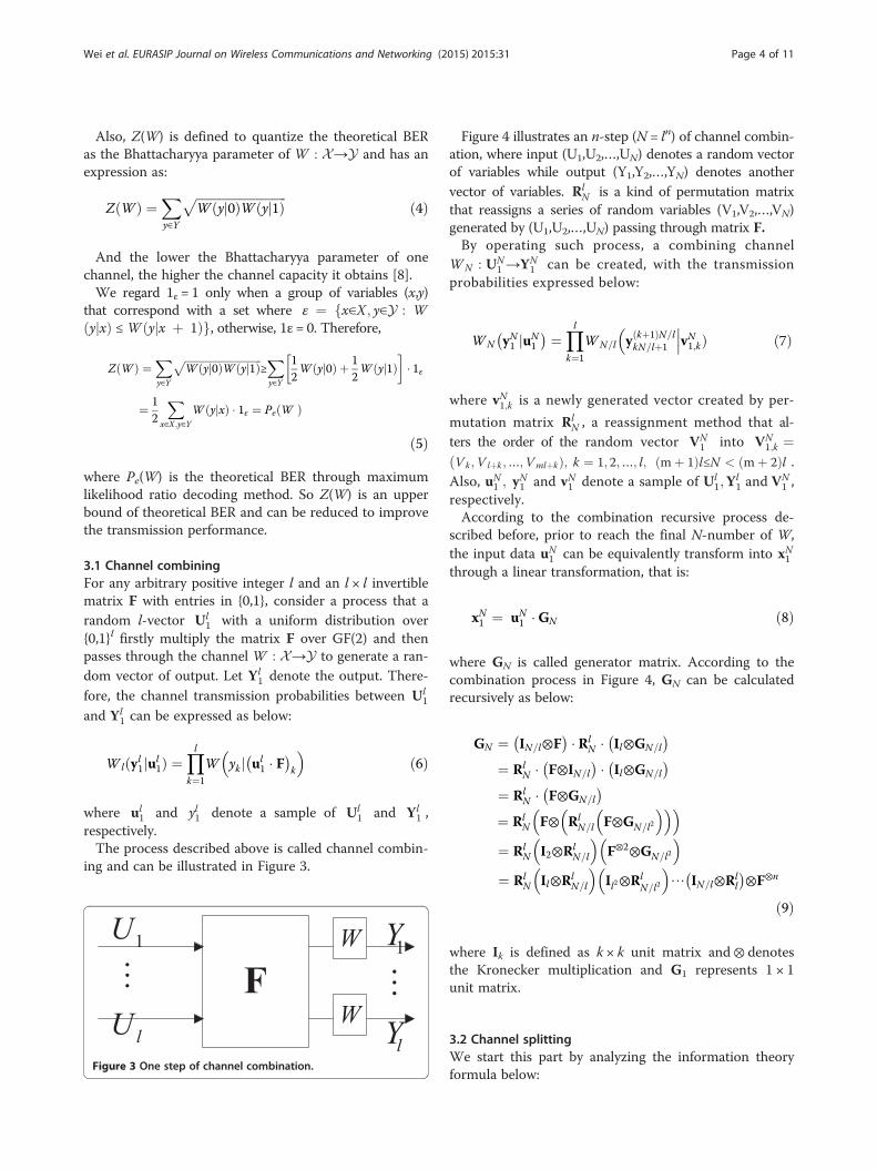
3.1 Channel combiningFor any arbitrary positive integer l and an l × l invertiblematrix F with entries in {0,1}, consider a process that arandom l-vector Ul
1 with a uniform distribution over{0,1}l firstly multiply the matrix F over GF(2) and thenpasses through the channel W : X→Y to generate a ran-dom vector of output. Let Yl
1 denote the output. There-fore, the channel transmission probabilities between Ul
1
and Yl1 can be expressed as below:
Wlðyl1jul1Þ ¼
Ylk¼1
W yk j ul1 � F
� k
� �ð6Þ
where ul1 and yl1 denote a sample of Ul
1 and Yl1 ,
respectively.The process described above is called channel combin-
ing and can be illustrated in Figure 3.
Figure 3 One step of channel combination.
Figure 4 illustrates an n-step (N = ln) of channel combin-ation, where input (U1,U2,…,UN) denotes a random vectorof variables while output (Y1,Y2,…,YN) denotes anothervector of variables. Rl
N is a kind of permutation matrixthat reassigns a series of random variables (V1,V2,…,VN)generated by (U1,U2,…,UN) passing through matrix F.By operating such process, a combining channel
WN : UN1 →YN
1 can be created, with the transmissionprobabilities expressed below:
WN yN1 juN1
� ¼ Ylk¼1
WN=l y kþ1ð ÞN=lkN=lþ1 vN1;kÞ
����ð7Þ
where vN1;k is a newly generated vector created by per-
mutation matrix RlN , a reassignment method that al-
ters the order of the random vector VN1 into VN
1;k ¼Vk ;V lþk ;…;VmlþkÞ; k ¼ 1; 2;…; l; mþ 1ð Þl≤N < mþ 2ð Þlð .Also, uN
1 ; yN1 and vN1 denote a sample of Ul
1;Yl1 and VN
1 ,respectively.According to the combination recursive process de-
scribed before, prior to reach the final N-number of W,the input data uN
1 can be equivalently transform into xN1through a linear transformation, that is:
xN1 ¼ uN1 �GN ð8Þ
where GN is called generator matrix. According to thecombination process in Figure 4, GN can be calculatedrecursively as below:
GN ¼ IN=l⊗F� � Rl
N � Il⊗GN=l
� ¼ Rl
N � F⊗IN=l
� � Il⊗GN=l
� ¼ Rl
N � F⊗GN=l
� ¼ Rl
N F⊗ RlN=l F⊗GN=l2
� �� �� �¼ Rl
N I2⊗RlN=l
� �F⊗2⊗GN=l2
� �¼ Rl
N Il⊗RlN=l
� �Il2⊗Rl
N=l2
� �⋯ IN=l⊗Rl
l
� ⊗F⊗n
ð9Þ
where Ik is defined as k × k unit matrix and⊗ denotesthe Kronecker multiplication and G1 represents 1 × 1unit matrix.
3.2 Channel splittingWe start this part by analyzing the information theoryformula below:
Figure 4 n-step of channel combination.
Wei et al. EURASIP Journal on Wireless Communications and Networking (2015) 2015:31 Page 5 of 11
I UN1 ;Y
N1
� ¼ XNi¼1
IðUi;YN1 jUi−1
1 Þ
¼XNi¼1
I Ui;YN1 ;U
i−11
� −I Ui;Ui−1
1
� � ¼
XNi¼1
I Ui;YN1 ;U
i−11
� ð10Þ
where I Ui;Ui−1ð Þ1
� �¼ 0 because of the independent
source UN1 .
Define WiN : Ui→YN
1 � U i−1ð Þ1 ; 1≤i≤N as a channel by
splitting the combining channel WN : UN1 →YN
1 based onEquation 10 and calculate transmission probabilities:
WiN yN1 ;u
i−11 jui
� ¼ Pr yN1 ;ui1
� Pr uið Þ �
XuNiþ1
Pr uNiþ1
� ¼
XuNiþ1
Pr yN1 ;uN1
� Pr uið Þ
¼XuNiþ1
Pr yN1 juN1
� Pr uið Þ Pr uN
1
� ð11Þ
Therefore, by combining the transition probabilities ofWi
N and WiN=l, the recursive formula is:
Wl i−1ð ÞþjN yN1 ; u
l i−1ð Þþj−11 jul i−1ð Þþj
� �¼ 1
2l−1Xuli
ul i−1ð Þþjþ1
Ylk¼1
WiN=l y 1þkð ÞN=l
kN=lþ1 ; vl i−1ð Þ1;k j uli
l i−1ð Þþ1 � F� �
k
�ð12Þ
In Formula 12 vili−1ð Þlþ1 ¼ uili−1ð Þlþ1F, 1 ≤ i ≤N/l, and 1 ≤
j ≤ l.Example 1: Arikan’s scheme given that:
F ¼ 1 01 1
� �We can calculate a generator matrix GN. with a
specified N = 2n. In order to select split channels fortransmissions, Arikan has provided a set of formulas[8] to calculate the Bhattacharyya parameter of eachsplit channel, that is:
Z W 2i−1N
� ¼ −Z WiN=2
� �2þ 2Z Wi
N=2
� �Z W 2i
N
� ¼ Z WiN=2
� �2
8><>: ð13Þ
Wei et al. EURASIP Journal on Wireless Communications and Networking (2015) 2015:31 Page 6 of 11
As well, when utilizing successive cancellation (SC) de-code method, it may come up with a set of formulas tocalculate likelihood ratio,
L2i−1N yN1 ; u2i−21
� ¼ LiN=2 yN=21 ; u2i−2
1;1 ⊕u2i−21;2
� �LiN=2 yNN=2þ1; u
2i−21;2
� �þ 1
LiN=2 yN=21 ; u2i−2
1;1 ⊕u2i−21;2
� �þ LiN=2 yNN=2þ1; u
2i−21;2
� �L2iN yN1 ; u
2i−11
� ¼ LiN=2 yN=21 ; u2i−2
1;1 ⊕u2i−21;2
� �h i1−2u2i−1 � LiN=2 yNN=2þ1; u2i−21;2
� �8>>>><>>>>:
ð14Þ
These formulas are only available for the 2 × 2 matrix
F ¼ 1 01 1
� �, however, but not for other specified
matrix, which limits the wide application of polar code.In order to tackle this problem, we first should to iden-tify what kind of matrix has the feature to generate polarcode, and this feature referred as to polarization feature.
3.3 Polarization feature
Define Wk : 0; 1f g →Yk as a channel with an input x,outputs yk1 and transmission probabilities:
Wk yk1jx� ¼ Yk
j¼1
W yjjx� �
ð15Þ
Wk : 0; 1f g →Yk implies a channel extension of W :X→Y, which has a Bhattacharyya parameter:
ð16ÞNote that Z(W)∈[0,1], so limk→∞Z(W)k = 0, which im-
plies that by extending channel W : X→Y , we, to someextent, can improve the transmission performance.Therefore, a paraphrase is given for channel polarization,
F is a polarizing matrix when there exists at least ani∈{1,2,…,l}, makes sense that:
Z Wil
� ∝Z Wð Þk ð17Þ
Some attributes of a polarizing matrix F maybe ofinterest. When the last row of F has k > 1 unit elements,
whose subscripts compose a set J = {j1,j2,…,jk}, then thetransmission probability of Wl
l can be calculated by:
Wll y
l1;u
l−11 jul
� ¼ 1
2l−1Wl yl1jul
1
� ¼ 1
2l−1Ylj¼1
W yjj ul1 � F
� j
� �ð18Þ
Accordingly, the Bhattacharyya parameter is given asbelow:
ð19Þwhich satisfies Equation 17, and Fl-1 denotes a sub-matrix of F by removing its last row.Consider more general circumstances in which any
split channel Wl−il with transmission probability:
Wl−il yl1;u
l−i−11 jul−i
� ¼ 1
2l−1Xull−iþ1
Wl yl1jul
1
� ¼ 1
2l−1Xull−iþ1
Pr yl−11 jul1
� � Pr yl yl−11 ;ul
1���
ð20ÞWhen the last row of F has only one unit element, due
to the permutation feature, we assume the unit elementis the last element in this row; then, the channel trans-mission probability can be rewritten into:
Wl−il yl1;u
l−i−11 jul−i
� ¼ 1
2l−1Xull−iþ1
Pr yl−11 jul−11
� � Pr yljyl−11 ;ul1
� ¼ 1
2l−1W ylj0ð Þ þW ylj1ð Þ½ � �
Xul−1l−iþ1
Wl−1 yl−11 ul−11 Þ���
ð21ÞTherefore, the output Yl is independent of inputs to
the channel Wl−il , indicating that the split channels W 1
l ;
W 2l ;…;Wl−1
l are defined on matrix Fl − 1, which are ob-tained by removing the last row and last column of F.Based in a recursive analysis on Fl − i, we may finally
conclude that a matrix F does not have polarization fea-ture when F is an upper triangular matrix.
3.4 Two difficulties of a polar codeTwo technical difficulties remain in how to design con-structing and decoding schemes for a generalized polar
Wei et al. EURASIP Journal on Wireless Communications and Networking (2015) 2015:31 Page 7 of 11
code that based on any specified matrix. That is, firstly,we need Bhattacharyya parameters of each split channelsto select channels for data transmission. Secondly, agroup of recursive formulas is demanded as a necessityof preparation to implement decoding scheme, thesuccessive cancellation decode (SC). There come two al-gorithms we proposed, to cope with the two realisticchallenges we mentioned.
3.5 Recursive Z algorithmFor a more general case, we firstly propose an algorithmcalculating Bhattacharyya parameters by defining c0 ¼ui−11 ; 0; tliþ1
� ⋅F and c1 ¼ ui−1
1 ; 1;wliþ1
� ⋅F. S0 is a set of in-
dices that where both c0 and c1 are equal to 0, while S1 isa set of indices that indicate the elements of both c0 andc1 are equal to 1. Therefore, the Bhattacharyya parameterof each split channel Wl
where (c0)j and (c1)j denote the jth element of c0 and c1.Thus, by traversing yl1;u
i−11 ; tliþ1;w
liþ1, respectively, we can
obtain Z Wil
� ; therefore, calculate Z Wi
N
� , recursively.
Example 2: given a matrix
F ¼1 0 01 0 11 1 1
24 35
with a BEC channel, according to the recursive Z algo-rithm above, the recursive Bhattacharyya parameters canbe calculated below:
Z W 3i−2N
� ¼ −Z WiN=3
� �3þ Z Wi
N=3
� �2þ Z Wi
N=3
� �Z W 3i−1
N
� ¼ −Z WiN=3
� �2þ 2Z Wi
N=3
� �Z W 3i
N
� ¼ Z WiN=3
� �3
8>>>>><>>>>>:ð23Þ
Figure 5 shows a three-step process of channelpolarization, each knot denotes a split channel and has avector, in which the left parameter represents e number
of split channels, while the right one represents the Bhat-tacharyya parameter. Knots on the right side are the splitchannels through this three-step polarization, of which thegreen ones are those good channels selected to transmitdata since the lower the Bhattacharyya parameter, thehigher the channel capacity they have gained.Therefore, by generating a 3 × 3 based polar code
scheme, we testified the recursive Z algorithm iseffective on constructing generalized polar codingscheme, which means as long as we can find a matrixthat has a polarization feature, we can realize a newpolar coding scheme based on that matrix. It has beentestified that in order to gain a higher error exponentthan 0.5, the length of a polarization matrix has to bemore than 16 [9,10].
3.6 Recursive likelihood ratio algorithmWe define likelihood ratio in SC decode method asbelow,
LiN yN1 ; ui−11
� ¼ WiN yN1 ; u
i−11 juib ¼ 0
� �Wi
N yN1 ; ui−11 juib ¼ 1
� � ð24Þ
where ui−11 denotes the received data whose values
have been decided successively, while ûi denotes a stat-istical decision of ui, whose value has not been decidedyet.Obviously, through Expression 13, we can literally cal-
culate LiN yN1 ; ui−11
� , but amounts of complexity accom-
panies. Instead, a more efficient FFT-like method isproposed to calculate LiN yN1 ; u
i−11
� based on the recur-
sive feature of polar code.The likelihood ratio can be rewritten as below:
Lil yl1; u
i−11
� ¼ Wil yl1; u
i−11 juib ¼ 0
� �Wi
l yl1; ui−11 juib ¼ 1
� �
¼X
tliþ1
Wl yl1jui−11 ; 0; vliþ1
� X
wliþ1
Wl yl1jui−11 ; 1;wl
iþ1
� ¼
Xtliþ1
Yl
j¼1W yjj c0ð Þj
� �X
wliþ1
Yl
j¼1W yjj c1ð Þj
� �ð25Þ
Note S0 as a set of indices where c0 equal to 0, whileS1 denotes a set of indices where c1 equals to 0. Con-sider that:
Xtliþ1
Ylj¼1
W yjj1� �
¼Xwl
iþ1
Ylj¼1
W yjj1� �
ð26Þ
EXPERIMENTAL EVALUATION
0 0.2 0.4 0.6 0.8 10
100
200
300
400
500
600
700
Bhattacharyya Parameters
Spl
ittin
g C
hann
els
Cou
nt
Figure 6 Channel polarization histogram.
Figure 5 Process of channel polarization.
Wei et al. EURASIP Journal on Wireless Communications and Networking (2015) 2015:31 Page 8 of 11
The numerator and denominator of the right side ofExpression 25 can be expressed, respectively:Yl
j¼1W yjj c0ð Þj
� �Yl
j¼1W yjj1
� � ¼Yj∈S0
L11 yj� �
Yl
j¼1W yjj c1ð Þj
� �Yl
j¼1W yjj1
� � ¼Yj∈S1
L11 yj� �
8>>>>>>><>>>>>>>:ð27Þ
Thus:
Lil yl1; u
i−11
� ¼X
tliþ1
Yj∈S0
L11 yj� �
Xwl
iþ1
Yj∈S1
L11 yj� � ð28Þ
By traversing ui−11 ; tliþ1;w
liþ1 , respectively, we can calcu-
late Lil yl1; u
i−11
� depending on various ui−1
1 , and recursively
calculate LiN yN1 ; ui−11
� .
Example 3: Consider the matrix given before with aBEC channel:
F ¼1 0 01 0 11 1 1
24 35
The recursive form of likelihood ratio based on recur-sive likelihood ratio algorithm can be calculated below:
L3i−2N yN1 ; u3i−31
� ¼ αβγ þ αγ þ βþ 1βγ þ αβ þ αþ γ
L3i−1N yN1 ; u3i−21
� ¼¼ αβγ þ 1βþ αγ
� � 1−u3i−2ð Þ� βγ þ α
αβ þ γ
� �u3i−2
L3iN yN1 ; u3i−11
� ¼ α 1−2u3i−2ð Þ 1−2u3i−1ð Þβγ 1−2u3i−1ð Þ
8>>>>><>>>>>:ð29Þ
0 1 2 3 4 510
-5
10-4
10-3
10-2
10-1
100
BE
R
BPSK-LPA
0 1 2 3 4 510
-5
10-4
10-3
10-2
10-1
100
(Eb/N0)/dB
BPSK-NLPA
NoCode PolarCode3 PolarCode2 LDPC
Figure 7 BER performance of BPSK modulated signals.
Wei et al. EURASIP Journal on Wireless Communications and Networking (2015) 2015:31 Page 9 of 11
where: � �8
α ¼ LiN=3 yN=3
1 ; u3i−31;1 ⊕ u3i−3
1;2 ⊕ u3i−31;3
β ¼ LiN=3 y2N=3N=3þ1; u
3i−31;3
� �γ ¼ LiN=3 yN2N=3þ1; u
3i−31;2 ⊕ u3i−3
1;3
� �>>><>>>:
According to Equation 29, a FFT-like SC decode methodcan be created; that is, calculating each LiN yN1 ; u
i−11
� de-
mands only its three ex-step parameters, which recursively,creates a method that has only a complexity of O(Nlog3N).
4 Experimental simulationsIn the experimental simulations, we mainly focus on theline-of-sight (LOS) scenarios, in which the first LOS
0 1 2 3 4 510
-5
10-4
10-3
10-2
10-1
100
QPSK-LPA
NoCode PolarCode
1
1
1
1
1
(Eb
BE
R
Figure 8 BER performance of QPSK modulated signals.
path may have an extremely strong energy [11]. This isjustified by wide adoptions of beam-forming techniques[12,13]. In this case, the single-path complex Gaussianchannel can be used for the simplicity of analysis[14,15]. The sampling rate is relatively high at 60GHzband, which may be further reduced by some recent sig-nal processing techniques, such as sampling conversion[16] or compressive sensing. The code rate is fixed at 1/2,the erasure probability (∈) is 0.1. We give the rest of chan-nels with 0 bits. In the experiments, the classical polarcode composed by Arikan (i.e., l = 2), which is denotedby polarcode 2, is also used for comparative analysis.Meanwhile, the popular LDPC scheme, based on a 336/672 check matrix, proposed and approved by the IEEE802.11ad standard [6] has also been adopted.
3 PolarCode2 LDPC
0 1 2 3 4 50
-4
0-3
0-2
0-1
00
/N0)/dB
QPSK-NLPA
4 6 8 10
10-2
10-1
(Eb/N0)/dB
BE
R
16QAM-LPA
No code PolarCode3 PolarCode2 LDPC
6 8 10
10-2
10-1
16QAM-NLPA
Figure 9 BER performance of 16QAM modulated signals.
Wei et al. EURASIP Journal on Wireless Communications and Networking (2015) 2015:31 Page 10 of 11
Firstly, a channel polarization histogram based on:
F =
1 0 01 0 11 1 1
24 35 is shown in Figure 6. We may notice that
the ratio of Bhattacharyya parameters approaching to 0 is90%, while the ratio of those channels whose capacitiesare approaching to 1 is less than 10%. According to thechannel polarization theory proposed by Arikan [7], wecan conclude that the generalized matrix has thepolarization feature and the recursive Z algorithm can beused to effectively calculate Bhattacharyya parameters.In the simulations, BPSK, QPSK, and 16QAM are then
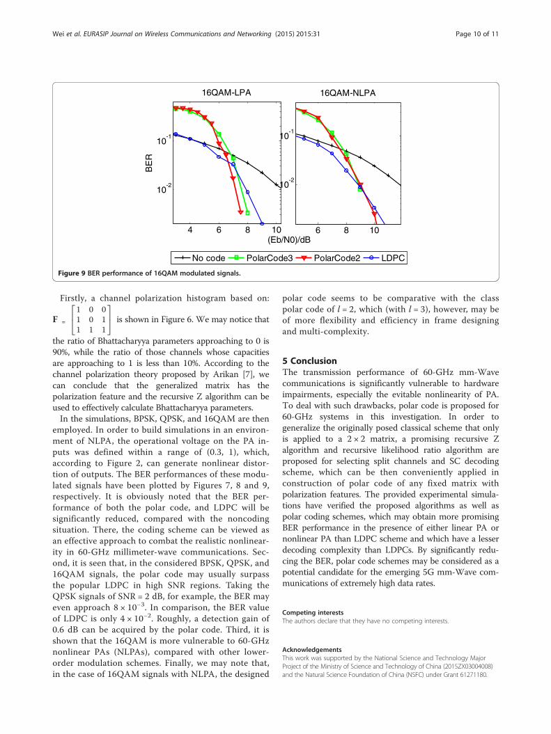
employed. In order to build simulations in an environ-ment of NLPA, the operational voltage on the PA in-puts was defined within a range of (0.3, 1), which,according to Figure 2, can generate nonlinear distor-tion of outputs. The BER performances of these modu-lated signals have been plotted by Figures 7, 8 and 9,respectively. It is obviously noted that the BER per-formance of both the polar code, and LDPC will besignificantly reduced, compared with the noncodingsituation. There, the coding scheme can be viewed asan effective approach to combat the realistic nonlinear-ity in 60-GHz millimeter-wave communications. Sec-ond, it is seen that, in the considered BPSK, QPSK, and16QAM signals, the polar code may usually surpassthe popular LDPC in high SNR regions. Taking theQPSK signals of SNR = 2 dB, for example, the BER mayeven approach 8 × 10⁻³. In comparison, the BER valueof LDPC is only 4 × 10⁻². Roughly, a detection gain of0.6 dB can be acquired by the polar code. Third, it isshown that the 16QAM is more vulnerable to 60-GHznonlinear PAs (NLPAs), compared with other lower-order modulation schemes. Finally, we may note that,in the case of 16QAM signals with NLPA, the designed
polar code seems to be comparative with the classpolar code of l = 2, which (with l = 3), however, may beof more flexibility and efficiency in frame designingand multi-complexity.
5 ConclusionThe transmission performance of 60-GHz mm-Wavecommunications is significantly vulnerable to hardwareimpairments, especially the evitable nonlinearity of PA.To deal with such drawbacks, polar code is proposed for60-GHz systems in this investigation. In order togeneralize the originally posed classical scheme that onlyis applied to a 2 × 2 matrix, a promising recursive Zalgorithm and recursive likelihood ratio algorithm areproposed for selecting split channels and SC decodingscheme, which can be then conveniently applied inconstruction of polar code of any fixed matrix withpolarization features. The provided experimental simula-tions have verified the proposed algorithms as well aspolar coding schemes, which may obtain more promisingBER performance in the presence of either linear PA ornonlinear PA than LDPC scheme and which have a lesserdecoding complexity than LDPCs. By significantly redu-cing the BER, polar code schemes may be considered as apotential candidate for the emerging 5G mm-Wave com-munications of extremely high data rates.
Competing interestsThe authors declare that they have no competing interests.
AcknowledgementsThis work was supported by the National Science and Technology MajorProject of the Ministry of Science and Technology of China (2015ZX03004008)and the Natural Science Foundation of China (NSFC) under Grant 61271180.
Wei et al. EURASIP Journal on Wireless Communications and Networking (2015) 2015:31 Page 11 of 11
Received: 22 September 2014 Accepted: 20 January 2015
UWB versus narrowband. IEEE Sensors J 11(6), 1448–1457 (2011)2. Q Liang, Automatic target recognition using waveform diversity in radar
sensor networks. Pattern Recognit Lett (Elsevier) 29(2), 377–381 (2008)3. J Liang, Q Liang, Design and analysis of distributed radar sensor networks.
IEEE Trans Parallel Distributed Process 22(11), 1926–1933 (2011)4. Federal Communications Commission. Code of federal regulations, part
15-Radio frequency devices section 15.255: operation within the band57.0-64.0 GHz. http://law.justia.com/cfr/title47/47-1.0.1.1.12.html47:1.0.1.1.12.3.236.35, Jan., 2001
5. SK Yong, P Xia, A Valdes-Garcia, 60 GHz Technology for Gbps WLAN andWPAN [M] (Wiley, Chichester, 2011). pp. 2–5
6. IEEE 802.11ad, Part 11: Wireless LAN Medium Access Control (MAC) andPhysical Layer (PHY) Specifications Amendment 3: Enhancements for Very HighThroughput in the 60 GHz Band [S], 2012
7. E Perahia, M Park, R Stacey, H Zhang, J Yee, V Ponnampalam, V Erceg, ABourdoux, C Cordeiro, R Maslennikov, S Shankar, A Maltsev, A Lomayev, CChoi, A Jain, M Hossein Taghavi, H Sampath, IEEE P802.11 wireless LANs TGadevaluation methodology [R]. IEEE 802.11 TGad Technology Report 09/0296r16,2010: 3–5, 9–15, 2010
8. E Arikan, Channel polarization: a method for constructing capacityachieving codes for symmetric binary-input memoryless channels. IEEETrans Inform Theory IT-55, 3051–3073 (2009)
9. S Dong-Min, L Seung-Chan, Y Kyeongcheol, Mapping selection and codeconstruction for 2Am-ary polar-coded modulation. Commun Lett16, 905–908 (2012)
10. Sasoglu, E Telatar, E Yeh, Polar codes for the two-user multiple access channel,Proceedings of the 2010 IEEE Information Theory Workshop, Cairo, Egypt,January 6–8, 2010
11. RG Gallager, Information Theory and Reliable Communication (Wiley, NewYork, 1968)
12. S Kato, H Harada, R Funada, T Baykas, C Sum, J Wang, M Rahman, Singlecarrier transmission for multi-gigabit 60-GHz WPAN system [J]. IEEE JSelected Areas Commun 27(8), 1466–1478 (2009)
13. H Xu, K Liu, Research on wireless communication networks in the 60GHzfrequency band [C] (International Conference on Internet Technology andApplications, Wuhan, China, 2010), pp. 1–4
14. B Li, Z Zhou, W Zou, On the efficient beam pattern training for 60GHzwireless personal area networks. IEEE Trans Wirel Commun12(2), 504–515 (2013)
15. B Li, Z Zhou, H Zhang, A Nallanathan, Efficient beamforming training for60-GHz millimeter-wave communications: a novel numerical optimizationframework. IEEE Trans Vehicular Technol 63(2), 703–771 (2014)
16. G Bi, K Mitra Sanjit, S Li, Sampling rate conversion based on DFT and DCT.Signal Process 93(2), 476–486 (2013)
Submit your manuscript to a journal and benefi t from: