Abstract: Propagation characteristics of truncated Localized Wavespropagating in dispersive silica and free space are numerically analyzed.It is shown that those characteristics are affected by the changes in therelation between the transverse spatial spectral components and the wavevector. Numerical experiments demonstrate that as the non-linearity of thisrelation gets stronger, the pulses propagating in silica become more immuneto decay and distortion whereas the pulses propagating in free-space sufferfrom early decay and distortion.
OCIS codes: (060.5530) Pulse propagation and temporal solitons; (350.5500) Propagation.
References and links1. H. A. Willebrand and B. S. Ghuman, “Fiber optics without fiber,” IEEE Spectr. 38, 40–45 (2001).2. L. B. Felsen, “Phase space issues in ultrawideband/short pulse wave modeling,” in Ultra-Wideband, Short-Pulse
Electromagnetics, H. Bertoni, L. Carin, and L. B. Felsen, eds. (Plenum Press, New York, 1993).3. J.-Y. Lu, J. Cheng, and B. Cameron, “Low sidelobe limited diffraction optical coherence tomography,” in “Co-
herence Domain Optical Methods in Biomedical Science and Clinical Applications VI, Proc. of SPIE,” , vol.4619, V. V. Tuchin, J. A. Izatt, and J. G. Fujimoto, eds. (SPIE, 2006), vol. 4619, pp. 300–311.
4. T. Ito and S. Okazaki, “Pushing the limits of lithography,” Nature 406, 1027–1031 (2000).5. J. N. Brittingham, “Focus waves modes in homogeneous Maxwell’s equations: transverse electric mode,” J. Appl.
Phys. 54, 1179–1189 (1983).6. J.-Y. Lu and J. F. Greenleaf, “Nondiffracting X waves: exact solutions to free-space scalar wave equation and
their infinite realizations,” IEEE Trans. Ultrason. Ferroelectr. Freq. Control 39, 19–31 (1992).7. R. W. Ziolkowski, “Exact solutions of the wave equation with complex source locations,” J. Math. Phys. 26,
861–863 (1985).8. A. M. Shaarawi, “Comparison of two localized wave fields generated from dynamic apertures,” J. Opt. Soc. Am.
A 14, 1804–1816 (1997).9. E. Heyman, B. Z. Steinberg, and L. B. Felsen, “Spectral analysis of focus wave modes,” J. Opt. Soc. Am. A 4,
2081–2091 (1987).10. E. Heyman, “The focus wave mode: a dilemma with causality,” IEEE Trans. Antenn. Propag. 37, 1604–1608
(1989).11. H. E. Hernandez-Figueroa, M. Zamboni-Rached, and E. Recami, eds., Localized waves (J. Wiley & Sons, New
York, NY, 2008).12. A. M. Shaarawi, R. W. Ziolkowski, and I. M. Besieris, “On the evanescent fields and the causality of the focus
wave modes,” J. Math. Phys. 36, 5565–5587 (1995).13. M. Zamboni-Rached, “Subluminal wave bullets: Exact localized subluminal solutions to the wave equations,”
Phys. Rev. A 77, 033824 (2008).14. M. Zamboni-Rached, “Unidirectional decomposition method for obtaining exact localized wave solutions totally
free of backward components,” Phys. Rev. A. 79, 013816 (2009).15. A. Sezginer, “A general formulation of focus wave modes,” J. Appl. Phys. 57, 678–683 (1985).16. T. T. Wu and H. Lehmann, “Spreading of electromagnetic pulses,” J. Appl. Phys. 58, 2064–2065 (1985).17. R. W. Ziolkowski, “Localized transmission of electromagnetic energy,” Phys. Rev. A. 39, 2005–2033 (1989).18. I. M. Besieris, A. M. Shaarawi, and R. W. Ziolkowski, “A bidirectional travelling plane wave representation of
exact solutions of the scalar wave equation,” J. Math. Phys. 30, 1254–1269 (1989).
#133566 - $15.00 USD Received 24 Aug 2010; revised 18 Oct 2010; accepted 4 Nov 2010; published 22 Nov 2010(C) 2010 OSA 6 December 2010 / Vol. 18, No. 25 / OPTICS EXPRESS 25482
19. H. Sonajalg and P. Saari, “Suppression of temporal spread of ultrashort pulses in dispersive media by Besselbeam generators,” Opt. Lett. 21, 1162–1164 (1996).
20. M. A. Porras, “Diffraction-free and dispersion-free pulsed beam propagation in dispersive media,” Opt. Lett. 26,1364–1366 (2001).
21. S. Orlov, A. Piskarskas, and A. Stabinis, “Localized optical subcycle pulses in dispersive media,” Opt. Lett. 27,2167–2169 (2002).
22. M. Zamboni-Rached, K. Z. Nobrega, H. E. Hernandez-Figueroa, and E. Recami, “Localized superluminal so-lutions to the wave equation in (vacuum or) dispersive media, for arbitrary frequencies and with adjustablebandwidth,” Opt. Commun. 226, 15–23 (2003).
23. R. Donnelly and R. W. Ziolkowski, “Designing localized waves,” Proc. R. Soc. Lond. A 440, 541–565 (1993).24. G. P. Agrawal, Nonlinear Fiber Optics (Academic Press, New York, 1995), 2nd ed.25. A. M. Shaarawi, S. M. Sedky, R. W. Ziolkowski, and I. M. Besieris, “The spatial distribution of the illumination
of dynamic apertures and its effect on the decay rate of the radiated localized pulses,” J. Phys. Math. Gen. 29,5157–5179 (1996).
1. Introduction
Undistorted pulse propagation is a subject of great interest due to its various applications inhigh-speed and long-distance communication [1], energy transfer [2], medical radiography [3],and optical lithography [4]. Localized Waves (LWs) [5], which represent a family of solutionsto the homogeneous scalar wave equation, can propagate long distances without distortion.Peaks of an ideal and infinite-energy LW propagate with an arbitrary but constant speed alonga straight line; and the ideal LW maintains its shape rigidly or with only local deformationsfor all time. This is a result of the inherent coupling between the wave’s temporal and spatialspectra. Depending on the type of this coupling, LWs can be categorized into two main groups:(i) X-waves [6] and (ii) Focus Wave Modes (FWM) [5, 7]. For X-waves, the coupling relationis linear; and the waves in this group are solely composed of forward propagating components.The coupling relation for FWMs is parabolic [8]; and the waves in this group have backwardpropagating components [9, 10]. Accordingly, X-waves were widely favored in studies due totheir causal structure, and the linear nature of their spectra coupling relation (see, e.g. [11] andreferences therein). Initially FWMs were thought to be physically non-realizable because of thepresence of backward propagating wave components, but it was later shown that a physicallyrealizable approximation an be obtained by letting the forward propagating components domi-nate over the backward propagating ones [12]. Moreover, several LW solutions from the FWMfamily were constructed to be naturally free from backward propagating components [13, 14].
An important critique to the physical realization of ideal LW solution is the infinite energyrequirement [15]. Wu and Lehmann [16] proved that the energy density of any finite-energysolution to the source-free Maxwell’s equations approaches zero as time tends to infinity, thusno finite-energy LW solution that can propagate to infinity without distortion could physicallyexist. To achieve an approximately-undistorted propagation while meeting the finite-energyrequirement, several finite-energy LW solutions were constructed [13, 17]. Additionally, theideal infinite-energy LW solution could be truncated in space and time (e.g., using dynamicGaussian apertures [18]) to achieve the same goal.
A special area of interest for LW applications is in the field of optics and photonics [1–4]. A considerable amount of work was published on the characterization of optical (high-frequency) LW propagation (see chapters 7-12 in [11]); however only a few studies focusedon their propagation in dispersive media [19–22]. In [19–21] closed form expressions for LWspropagating in dispersive media are presented; however, these expressions are assumed to holdonly within a limited spectral band. In [22], generic spectral expressions are given only forsuperluminal infinite-energy X-waves propagating in a dispersive medium.
In this paper, the propagation characteristics of truncated (finite-energy) LWs propagatingin dispersive silica are analyzed and compared to those of truncated LWs propagating in free-
#133566 - $15.00 USD Received 24 Aug 2010; revised 18 Oct 2010; accepted 4 Nov 2010; published 22 Nov 2010(C) 2010 OSA 6 December 2010 / Vol. 18, No. 25 / OPTICS EXPRESS 25483
Fig. 1. The spectrum of the pulses | ˜ψ(kρ ,0,ω)| showing the coupling between the spatialkρ and temporal ω spectral components of the (a) X-wave (α = 0), (b) FWM with (aα =0.02), (c) FWM with (aα = 2.0) , (d) FWM with (aα = 5.0) , (e) FWM with (aα = 10.0)and (f) FWM with (aα = 20.0). Exact coupling relation, that is obtained by substitutingEq. (3) into Eq. (2) is shown in red circles for reference.
#133566 - $15.00 USD Received 24 Aug 2010; revised 18 Oct 2010; accepted 4 Nov 2010; published 22 Nov 2010(C) 2010 OSA 6 December 2010 / Vol. 18, No. 25 / OPTICS EXPRESS 25484
space. The truncation, which is necessary for physical realization of the pulses, is achieved bymultiplying the ideal infinite-energy LW solution by spatial and temporal Gaussian windows.This procedure is equivalent to truncating the spatial and temporal spectra of the LW as dis-cussed later on. The spectral truncation is carried out in such a way that (possible) backwardpropagating components are filtered out. Because of the truncation, the inseparable couplingof the spatial and temporal spectra is not rigorously enforced; and hence the resulting pulsessuffer from distortion and decay. Several numerical experiments were performed to quantifythose effects and relate them to the spectral structure of the pulses.
The remainder of the paper is organized as follows: Section 2 starts with the general expres-sion of LWs; describes the necessary condition for undistorted propagation, and discusses theeffects of the spatial and the temporal truncation on the spectral structure of the LW. Section3 provides several numerical experiments where the propagation characteristics of LWs prop-agating in free-space and silica are compared. Furthermore, it discusses the relation betweenthose characteristics and the LW spectral structure. Section 4 summarizes the discussions ontruncated LWs propagation in dispersive silica and provides future research avenues.
2. Formulation and discussion
A cylindrically symmetric scalar field ψ(ρ ,z, t), which represents the LW-type solution of thehomogeneous wave equation and propagates along the z-direction, can be constructed by apolychromatic superposition of Bessel beams [18], using
ψ(ρ ,z, t) =∫ ∞
0kρdkρ
∫ ∞
−∞dkz
∫ ∞
−∞dωψ(kρ ,kz,ω)J0(kρ ρ)ei(kzz−ωt). (1)
Here, {kρ ,kz,ω} and {ρ ,z, t} are the spectral, and spatial and temporal variables, respectively,ψ(kρ ,kz,ω) is the spectral amplitude of the LW, and J0(.) is the zeroth order Bessel functionof the first kind. The spectral variables satisfy the dispersion relation
k2ρ + k2
z =(
n(ω)ωc
)2, (2)
where n(ω) is the refractive index of the medium and c is speed of light in free-space. Fully-undistorted pulse propagation can only be achieved if the pulse is capable of reconstructingitself periodically. In other words ω and kz must satisfy [23]
ω = α + v0kz, (3)
where v0 is the pulse peak velocity and α is an arbitrary constant that quantifies the periodicityof the field shape along the z-direction. For undistorted LW propagation, conditions (2) and (3)must both hold true for all values of the spectral variables, kρ , kz and ω . In mathematical terms,this can be achieved using Dirac-delta functions (in the generalized sense); i.e., choosing
ψ(kρ ,kz,ω) = ψ ′(ω)δ
(kρ −
√(n(ω)
ωc
)2− k2
z
)δ(
kz − ω −αv0
), (4)
where ψ ′(ω) is an arbitrary spectral amplitude function. Inserting Eq. (4) into Eq. (1) yields
ψ(ρ ,z, t) =∫ ωmax
ωmin
dωψ ′(ω)ξ1J0(ξ1ρ)ei(ξ2z−ωt),
ξ1 =
√(n(ω)
ωc
)2−ξ 2
2 , (5)
ξ2 =ω −α
v0.
#133566 - $15.00 USD Received 24 Aug 2010; revised 18 Oct 2010; accepted 4 Nov 2010; published 22 Nov 2010(C) 2010 OSA 6 December 2010 / Vol. 18, No. 25 / OPTICS EXPRESS 25485
The limits of integration ωmin and ωmax are chosen as
ωmin =αc
max(c−n(ω)v0),
ωmax =αc
min(c−n(ω)v0),
(6)
to ensure that ξ1 ≥ 0, i.e., to avoid non-physical solutions.Several observations about Eqs. (4) and (5) are in order:
i) The ‘ordinary’ X-wave [6] and FWM waves [5, 7] can be recovered by setting the spectralamplitude function to ψ ′(ω) = (ω/v0)
m exp(−aω), where a is an arbitrary positive realconstant and m = 0,1,2, . . . is the order of the pulse. X-wave solutions are obtained bysetting α = 0, while for FWM solutions α > 0 [18].
ii) The presence of a non-zero α in the pulse spectrum yields backward propagating (acuasal)field components, thus especially for non-truncated LWs, it is important to choose thepulse parameters such that the causal components dominate over the acausal ones. This istypically achieved by setting aα � 1 [18].
iii) Any ψ(ρ ,z, t) satisfying Eq. (5) (including X-wave and FWM solutions) extend from −∞to +∞ in both space and time [18]. To achieve practically realizable pulses, ψ(ρ ,z, t) hasto be truncated in space and time. In this work, the LWs are truncated in space and timevia multiplication with
ft(t) =
{e−(t/T ) |t| ≤ 2T0 elsewhere
and fρ(ρ) ={
e−(ρ/R) ρ ≤ 2R0 elsewhere
. (7)
iv) Multiplying ψ(ρ ,z, t) with functions ft(t) and fρ(ρ) given in Eq. (7) is equivalent toconvolving ψ(kρ ,kz,ω) with their spectra, ft(ω) and fρ(kρ), respectively. Writing thespectrum [Eq. (4)] in terms of kz as ψ(kρ ,kz,ω) = ψ ′′(kz)δ (kρ − χ1)δ (ω − χ2) withχ1 = {(n(χ2)/c)2α(α + 2v0kz)+ [(n(χ2)v0/c)2 − 1]k2
z}1/2 and χ2 = α + v0kz, then per-forming the convolution with the truncating functions spectra yields
Considering that ft(.) and fρ(.) are Gaussian type functions, it becomes clear that the con-volution operations truncate the spectra of ψ(ρ ,z, t). As a result, one can choose T and Rproperly to eliminate/suppress the spectral content corresponding to backward propagatingcomponents (This procedure is analogous to the finite-time dynamic aperture excitationanalyzed in [8]). In the remainder of the paper, the truncated pulse and its spectrum arerepresented by ψ(ρ ,z, t) and ˜ψ(kρ ,kz,ω), respectively.
v) It should be noted here that replacing the spectrum [Eq. (4)] with Eq. (8) yields a fieldthat is not an exact solution to the homogeneous wave equation. Yet this field is expandedin terms of Bessel beams, which are exact solutions to the homogeneous wave equation,and propagated as such. Thus the truncated spectrum should be understood as an imposedinitial condition, whereas the propagated field rigidly satisfies the wave equation.
vi) As a result of truncation, the undistorted propagation condition (3) is not rigorously en-forced for all values of the spectral variables in the spectrum [Eq. (8)]. This eventuallyresults in distortion and decay of the pulses during propagation [16].
#133566 - $15.00 USD Received 24 Aug 2010; revised 18 Oct 2010; accepted 4 Nov 2010; published 22 Nov 2010(C) 2010 OSA 6 December 2010 / Vol. 18, No. 25 / OPTICS EXPRESS 25486
Fig. 2. Comparison of the spatial spectral depletion of the pulses propagating in free-spaceand silica at z′ = 0, z′ = zD and z′ = 2zD for (a) X-wave (α = 0), (b) FWM with (aα =0.02), (c) FWM with (aα = 2.0), (d) FWM with (aα = 5.0), (e) FWM with (aα = 10.0)and (f) FWM with (aα = 20.0).
#133566 - $15.00 USD Received 24 Aug 2010; revised 18 Oct 2010; accepted 4 Nov 2010; published 22 Nov 2010(C) 2010 OSA 6 December 2010 / Vol. 18, No. 25 / OPTICS EXPRESS 25487
3. Numerical experiments
Several numerical experiments are performed to understand the relation between the spec-tral structure and depletion, and the propagation characteristics of truncated LWs prop-agating in a dispersive medium; specifically to quantify the effect of the parameter αon the propagation characteristics of truncated X-wave (α = 0) and FWM waves (aα ={0.02,2.0,5.0,10.0,20.0}) in bulk fused silica. In all experiments, the pulses are also prop-agated in free-space, as a non-dispersive medium, for comparison purpose. The silica refractiveindex is modeled using the empirical Sellmeier equation [24]
n2(ω) = 1+N
∑j=1
Bjω2j
ω2j −ω2
, (9)
where ω j is the j-th resonance frequency, Bj is the strength of the j-th resonance, and N isthe total number of material resonances in the frequency range of interest. For a typical fusedsilica medium [24], N = 3, and the values of Bj and ω j are the ones listed in Table 1. It shouldbe noted that with the parameters given in Table 1, Eq. (9) is only accurate when used in thefrequency band ω ∈ [8.196,51.643]×1014rad [24].
Table 1. Values of Bj and ω j for typical bulk fused silica [see Eq. (9)]
For all pulses investigated in the experiments, m = 28 and a = 10−14s−1 (to confine thepulse’s temporal spectrum within the validity range of (9)); for pulses propagating in silica,v0 = c/1.44, R = 5× 10⁻⁵m, and T = 2.5× 10⁻¹³s; and for the pulses propagating in free-space, v0 = c, R = 7.5× 10⁻⁵m, and T = 1.75× 10⁻¹³s. The truncation windows for pulsespropagating in free-space are modified to compensate for the longer wavelengths in free-space.All pulses are assumed to be launched from an aperture at z = 0.
3.1. Spectral structure and depletion
As discussed above, the undistorted propagation relation (3) is not rigorously enforced whenthe LW is truncated. However, because the truncation windows ft(t) and fρ(ρ) are sufficientlywide enough, the spectrum is still confined around the kρ −ω line, described by Eqs. (2) and(3), at a constant kz. The amount of deviation in the spectrum from this line determines thelevel of distortion and decay that occurs during the propagation of the truncated LWs. Figure 1depicts the spectrum of the truncated LWs, | ˜ψ(kρ ,kz,ω)| at kz = 0. The figure shows that thespectra of the FWM pulses with higher α values follow more closely the kρ −ω line withinthe range with the significant spectral amplitude concentration. On the other hand, with theincrease in α , the deviation from this line within the range, where the spectral amplitudes aresmaller, becomes larger. As will be shown in Section 3.2, this deviation from the ideal kρ −ωline deteriorates the field depth of the pulse if it occurs within the range with higher spectralamplitudes. It should be noted that as the parameter α increases, the value of ωmin also increasesaccording to Eq. (6). Such increase in the lower limit of the integral (5) may result in truncationin the spectra as observed in Figs. 2(f) and 3(f) for the FWM pulse with (aα = 20.0).
In [25], the spectral structure of LWs launched from a dynamic aperture in free-space wasinvestigated and a relation between the spectral depletion and the field depth was established.
#133566 - $15.00 USD Received 24 Aug 2010; revised 18 Oct 2010; accepted 4 Nov 2010; published 22 Nov 2010(C) 2010 OSA 6 December 2010 / Vol. 18, No. 25 / OPTICS EXPRESS 25488
Fig. 3. Comparison of the temporal spectral depletion of the truncated pulses in free-spaceand silica at z′ = 0, z′ = zD and z′ = 2zD for (a) X-wave, (b) FWM with (aα = 0.02),(c)FWM with (aα = 2.0), (d) FWM with (aα = 5.0), (e) FWM with (aα = 10.0) and (f)FWM with (aα = 20.0).
#133566 - $15.00 USD Received 24 Aug 2010; revised 18 Oct 2010; accepted 4 Nov 2010; published 22 Nov 2010(C) 2010 OSA 6 December 2010 / Vol. 18, No. 25 / OPTICS EXPRESS 25489
Fig. 4. Normalized intensities at the centroid of the truncated pulses vesrus the propagationdistance in (a) free-space and (b) silica.
Thus, in order to extend this investigation to LW pulses propagating in silica as well as toquantify the effect of the parameter α on the relation between the pulse’s spectral depletion andits propagation characteristics, the following experiments are performed.
First, the behavior of the transverse spatial spectra of the pulses is investigated. The trans-verse spatial spectrum, Φρ(kρ ;z′), is obtained by computing the Bessel-Fourier transform ofthe truncated pulse at the pulse peak, (z = z′, t = z′/v0), viz.
Φρ(kρ ;z′) =∫ ∞
0ρdρψ
(ρ ,z′,
z′
v0
)J0(kρ ρ). (10)
The absolute value of the spectrum [Eq. (10)] is then normalized with respect to its maximum,viz., Φρn(kρ ;z′) = |Φρ(kρ ;z′)|/max(|Φρ(kρ ;0)|). Figure 2 presents Φρn(kρ ;z′) computed forall six types of pulses propagating in free-space and silica, at z′ = 0, z′ = zD and at z′ = 2zD,where zD is the distance at which the pulse intensity at the centroid drops to 1/e of its initialvalue [see Section 3.2]. The figure shows that the spatial spectra are expanded and shiftedtowards higher frequencies as α increases, yet the expansion and shift are more significant inthe free-space case. Comparison of the plots in Figs. 2(a) and 2(b) show that the spectra of theX-wave and the FWM with aα = 0.02 are very similar for the pulses propagating in silica, yetthere is a difference of several orders of magnitude in terms of bandwidth and frequency rangefor those propagating in free-space. The nature of the spatial spectral depletion is revealed bycomparing the spectra of the pulses at z′ = 0, z′ = zD and z′ = 2zD as shown in the figure. Theplots show that the spatial spectra deplete differently for pulses propagating in free-space andsilica. In free-space, all spatial frequency components deplete equally or with a slight tendencyto deplete more at the lower frequency components of the spectrum; however, in silica, thespatial spectra consistently deplete significantly more at the higher frequency components ofthe spectrum.
The relation between the depletion of the transverse spatial spectrum and that of the temporalspectrum determines the deviation from the ideal kρ −ω line as the pulses propagate. Thus inwhat follows, the behavior of the temporal spectra of the pulses propagating in free-space andsilica are investigated. The temporal spectrum Φt(ω;z′) is computed from the Fourier transformof the truncated pulse expressions at ρ = 0 and centered around the pulse peak, (z = z′, t =t − z′/v0), viz.
Φt(ω;z′) =∫ ∞
−∞dtψ
(0,z′, t − z′
v0
)eiωt . (11)
#133566 - $15.00 USD Received 24 Aug 2010; revised 18 Oct 2010; accepted 4 Nov 2010; published 22 Nov 2010(C) 2010 OSA 6 December 2010 / Vol. 18, No. 25 / OPTICS EXPRESS 25490
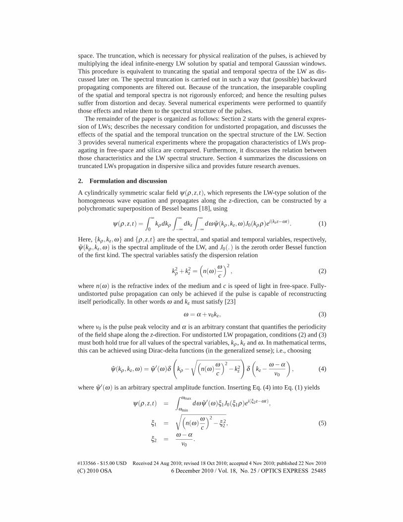
Fig. 5. Percentage change of the FWHM of the pulses along the propagation distance fromz = 0 to z = zD in (a) free-space and (b) silica.
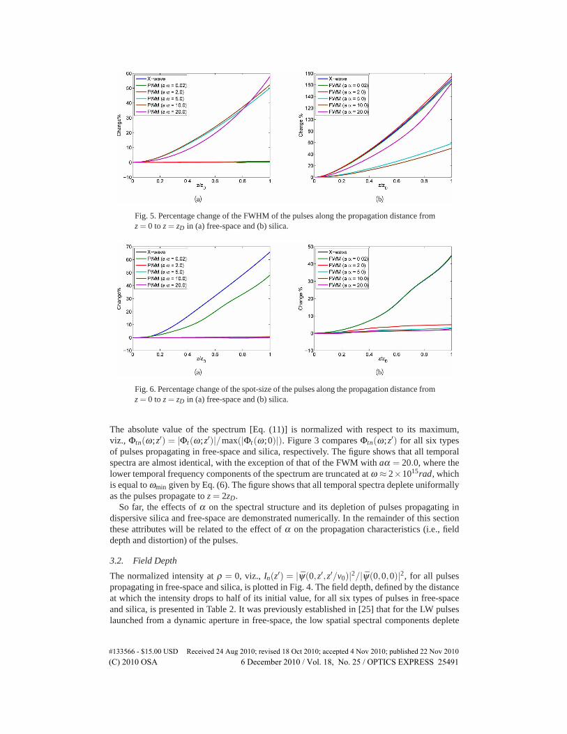
Fig. 6. Percentage change of the spot-size of the pulses along the propagation distance fromz = 0 to z = zD in (a) free-space and (b) silica.
The absolute value of the spectrum [Eq. (11)] is normalized with respect to its maximum,viz., Φtn(ω;z′) = |Φt(ω;z′)|/max(|Φt(ω;0)|). Figure 3 compares Φtn(ω;z′) for all six typesof pulses propagating in free-space and silica, respectively. The figure shows that all temporalspectra are almost identical, with the exception of that of the FWM with aα = 20.0, where thelower temporal frequency components of the spectrum are truncated at ω ≈ 2×10¹⁵rad, whichis equal to ωmin given by Eq. (6). The figure shows that all temporal spectra deplete uniformallyas the pulses propagate to z = 2zD.
So far, the effects of α on the spectral structure and its depletion of pulses propagating indispersive silica and free-space are demonstrated numerically. In the remainder of this sectionthese attributes will be related to the effect of α on the propagation characteristics (i.e., fielddepth and distortion) of the pulses.
3.2. Field Depth
The normalized intensity at ρ = 0, viz., In(z′) = |ψ(0,z′,z′/v0)|2/|ψ(0,0,0)|2, for all pulsespropagating in free-space and silica, is plotted in Fig. 4. The field depth, defined by the distanceat which the intensity drops to half of its initial value, for all six types of pulses in free-spaceand silica, is presented in Table 2. It was previously established in [25] that for the LW pulseslaunched from a dynamic aperture in free-space, the low spatial spectral components deplete
#133566 - $15.00 USD Received 24 Aug 2010; revised 18 Oct 2010; accepted 4 Nov 2010; published 22 Nov 2010(C) 2010 OSA 6 December 2010 / Vol. 18, No. 25 / OPTICS EXPRESS 25491
Table 2. Field depth of X-wave and FWM pulses propagating in free-space and silica
first with distance. Results obtained for pulses propagating in free-space agree with [25] aspresented in Figs. 2 and 4(a). On the other hand, for the LW pulses propagating in silica, re-sults show that higher spatial frequency components deplete first as shown in Fig. 2. Thus forLW pulses propagating in silica, the presence of α enhances the field depth. This could be ex-plained by the change in the nature of the coupling relation between ω and kρ . For X-wave andFWM pulses propagating in free-space ω ∝ kρ and ω ∝ k2
ρ , respectively [8]. This linear relationenhances the field localization of X-wave pulses because as both spatial and temporal spectradeplete, the undistorted propagation condition (3) is still preserved. The same relations do nothold true for the pulses propagating in a dispersive medium due to the frequency-dependentrefractive index. It should be noted that for the FWM with aα = 20.0 the field depth is less thanthat of the FWM with aα = 10.0; this is due to the truncation in the spectrum imposed by thephysical requirement of the choice of ωmin.
3.3. Pulse spreading
Truncated LW pulses spread in both time and space because of their finite energy con-tent [16]. To characterize the pulse spreading, the temporal and spatial pulse intensity pro-files are computed and compared for all six types of pulses. Figure 5 presents the percent-age change in the full-width half-maximum (FWHM) of pulses intensity at ρ = 0, defined asΔ% = 100× |(I(z)− I(0))|/I(0), where I(z) is the intensity FWHM at distance z, computedalong the propagation interval z ∈ [0,zD]. The figure shows that in free-space the truncated LWpulses only suffer from dispersion when aα > 1, where the pulse’s FWHM increases expo-nentially as the pulse propagates. For these large values of α and with the chosen truncationwindows, the FWM pulses behave like truncated Gaussian pulses. In silica, all pulses sufferfrom temporal spreading as they propagate, but contrary to those propagating in free-space, theFWM pulses with aα > 1 exhibit the least spreading. The pulse spreading in silica could bereadily explained by the nature of their spectral depletion shown in Figs. 2 and 3, where it isshown that the higher spatial frequency components are depleted before the lower components,while all temporal frequency components deplete almost uniformally. This uneven depletion inthe transverse spatial spectra and temporal spectra results in a non-linear relation between ωand kz; hence the different spectral components of the pulse propagate with different velocitiesresulting in temporal spreading.
The pulse spot-size, S(z), is defined by the FWHM of the intensity in the transverse planeat distance z. Figure 6 depicts the percentage change in the spot-size, defined by Δ% =100×|S(z)− S(0)|/S(0), computed along the same propagation interval z ∈ [0,zD], for all sixtypes of pulses. The figure shows that in free-space and silica, the FWM pulses with increasingα show less spreading in their spot-sizes. The presence of α in the LW expression forces aparabolic relation between ω and kρ in the free-space case, this non-linearity makes the kρ −ωmore immune to perturbations, resulting in less change in the spot-size. For pulses propagating
#133566 - $15.00 USD Received 24 Aug 2010; revised 18 Oct 2010; accepted 4 Nov 2010; published 22 Nov 2010(C) 2010 OSA 6 December 2010 / Vol. 18, No. 25 / OPTICS EXPRESS 25492
in silica, the relation between kρ and ω is not parabolic because of the frequency-dependent re-fractive index, yet the presence of α in this relation still increases the non-linearity and resultsin less change in the spot-size.
4. Conclusion
In this paper, the spectral structures of truncated LWs propagating in free-space and in dis-persive silica are analyzed. The analysis shows that in contrast to the pulses propagating infree-space, the presence of a parabolic relation between the wave vector and its transverse com-ponent enhances the field depth and suppresses pulse distortion.
Several numerical experiments are performed to determine the effect of the parameter α ,which defines the periodicity of the field shape along the z-direction, on the spectral structureof the truncated LWs propagating in free-space and silica. Results show that the field depth isenhanced when aα > 1 for pulses propagating in silica, in contrast to pulses propagating infree-space, where the field depth deteriorates for aα > 1. Results also show that the spectrawith higher values of α show stronger non-linearity in the relation between their spectral com-ponents, which renders them more immune to dispersion and distortion. On the other hand, thespectra are shifted towards higher values as α increases, which could lead to clipping in thespectra, and accordingly deterioration in the propagation characteristics.
Results presented in this paper are valuable for LW applications in various fields of scienceand engineering, including but not limited to, optical energy transfer, high-speed and long-distance communication systems, medical radiography and hyperthermia.
Analysis of the propagation characteristics of LWs propagating through slabs and refractingat interfaces of meta-materials, as well as back-scattering from penetrable objects, are under-way.
#133566 - $15.00 USD Received 24 Aug 2010; revised 18 Oct 2010; accepted 4 Nov 2010; published 22 Nov 2010(C) 2010 OSA 6 December 2010 / Vol. 18, No. 25 / OPTICS EXPRESS 25493