University of Birmingham On the structural response of a tall hybrid onshore wind turbine tower Gkantou, M.; Martinez-Vazquez, P.; Baniotopoulos, C. DOI: 10.1016/j.proeng.2017.09.535 License: Creative Commons: Attribution-NonCommercial-NoDerivs (CC BY-NC-ND) Document Version Publisher's PDF, also known as Version of record Citation for published version (Harvard): Gkantou, M, Martinez-Vazquez, P & Baniotopoulos, C 2017, 'On the structural response of a tall hybrid onshore wind turbine tower', Procedia Engineering, vol. 199, pp. 3200-3205. https://doi.org/10.1016/j.proeng.2017.09.535 Link to publication on Research at Birmingham portal Publisher Rights Statement: Checked for eligibility: 04/11/2019 General rights Unless a licence is specified above, all rights (including copyright and moral rights) in this document are retained by the authors and/or the copyright holders. The express permission of the copyright holder must be obtained for any use of this material other than for purposes permitted by law. • Users may freely distribute the URL that is used to identify this publication. • Users may download and/or print one copy of the publication from the University of Birmingham research portal for the purpose of private study or non-commercial research. • User may use extracts from the document in line with the concept of ‘fair dealing’ under the Copyright, Designs and Patents Act 1988 (?) • Users may not further distribute the material nor use it for the purposes of commercial gain. Where a licence is displayed above, please note the terms and conditions of the licence govern your use of this document. When citing, please reference the published version. Take down policy While the University of Birmingham exercises care and attention in making items available there are rare occasions when an item has been uploaded in error or has been deemed to be commercially or otherwise sensitive. If you believe that this is the case for this document, please contact [email protected] providing details and we will remove access to the work immediately and investigate. Download date: 17. Feb. 2022
Transcript
University of Birmingham
On the structural response of a tall hybrid onshorewind turbine towerGkantou, M.; Martinez-Vazquez, P.; Baniotopoulos, C.
Document VersionPublisher's PDF, also known as Version of record
Citation for published version (Harvard):Gkantou, M, Martinez-Vazquez, P & Baniotopoulos, C 2017, 'On the structural response of a tall hybrid onshorewind turbine tower', Procedia Engineering, vol. 199, pp. 3200-3205. https://doi.org/10.1016/j.proeng.2017.09.535
Link to publication on Research at Birmingham portal
Publisher Rights Statement:Checked for eligibility: 04/11/2019
General rightsUnless a licence is specified above, all rights (including copyright and moral rights) in this document are retained by the authors and/or thecopyright holders. The express permission of the copyright holder must be obtained for any use of this material other than for purposespermitted by law.
•Users may freely distribute the URL that is used to identify this publication.•Users may download and/or print one copy of the publication from the University of Birmingham research portal for the purpose of privatestudy or non-commercial research.•User may use extracts from the document in line with the concept of ‘fair dealing’ under the Copyright, Designs and Patents Act 1988 (?)•Users may not further distribute the material nor use it for the purposes of commercial gain.
Where a licence is displayed above, please note the terms and conditions of the licence govern your use of this document.
When citing, please reference the published version.
Take down policyWhile the University of Birmingham exercises care and attention in making items available there are rare occasions when an item has beenuploaded in error or has been deemed to be commercially or otherwise sensitive.
If you believe that this is the case for this document, please contact [email protected] providing details and we will remove access tothe work immediately and investigate.
X International Conference on Structural Dynamics, EURODYN 2017
On the structural response of a tall hybrid onshore wind turbine tower
M. Gkantoua*, P. Martinez-Vazqueza and C. Baniotopoulosa aSchool of Engineering, Department of Civil Engineering,University of Birmingham,Edgbaston, B15 2TT, UK
X International Conference on Structural Dynamics, EURODYN 2017
On the structural response of a tall hybrid onshore wind turbine tower
M. Gkantoua*, P. Martinez-Vazqueza and C. Baniotopoulosa aSchool of Engineering, Department of Civil Engineering,University of Birmingham,Edgbaston, B15 2TT, UK
2 Gkantou et al./ Procedia Engineering 00 (2017) 000–000
1. Introduction
Growing demand for clean and renewable energy has emerged owing to the increased amount of greenhouse emission gases. Wind farms consisting of lattice or tubular wind turbine towers have considerably contributed to an increase in the renewable energy production across the world. Demands for higher wind turbines with larger capacities, aimed to be installed at high altitudes or at places with high wind velocities, have recently appeared. In order to fulfil the required safety and durability verifications, whilst keeping the solution economically and environmentally sustainable, hybrid structures, efficiently combining tubular and lattice parts, could be applied. Towards this direction, the present study performs numerical analysis on a tall hybrid structure. Emphasis is placed upon three design load cases from those established in IEC64100-1 standard [1].
Nomenclature
CHS Circular Hollow Section DLC Design Load Case NTM Normal Turbulence Model ETM Extreme Turbulence Model
2. Methodology
The present paper focuses on the structural response of a 120 m hybrid onshore wind turbine tower. The current section presents the adopted methodology for the evaluation of its response. Subsection 2.1 describes the geometry of the considered hybrid tower and the employed cross-sections. Having established the wind turbine tower, a brief description of the aeroelastic analysis is given in Subsection 2.2.
2.1. Wind turbine tower
As a first step, a series of parameters, including the height of the tubular and the lattice part, the number of legs, the arrangements and the angle of bracings in the lattice part, need to be defined. An initial study should be carried out in order to find the most efficient structure, ensuring compromise between the lowest structural weight and the fabrication and assembly costs which commonly come as a function of the number of connections.
For the present study, a hybrid tower consisting of 60 m tube at the upper part and 60 m lattice structure at the lower part, as shown in Fig. 1, has been selected. In order to increase the load distribution, six columns (legs) have been chosen for the lattice structure. The employed cross-sections were based on a preliminary study [2]. Cold-formed built-up polygonal cross-sections in steel grade S355 were employed for both the tubular and the lattice part. For the simulation of the employed cross-sections of the hybrid tower herein, it was deemed adequate to model the polygonal cross-sections with circular hollow sections (CHS). The tubular part was tapered ranging from 5500 mm in the base to 4000 mm in the top, with constant plate thickness equal to 40 mm. The transition part was conservatively designed with bracings of large cross-sections. Note that the transition piece is a critical component, aiming to transfer all the dynamic and self-weight loads to the lattice, and needs separate in-depth investigation, out of the scope of the present paper. Various cross-sections, as can be seen in Fig. 1, were chosen for the lattice structure.
X International Conference on Structural Dynamics, EURODYN 2017
On the structural response of a tall hybrid onshore wind turbine tower
M. Gkantoua*, P. Martinez-Vazqueza and C. Baniotopoulosa aSchool of Engineering, Department of Civil Engineering,University of Birmingham,Edgbaston, B15 2TT, UK
X International Conference on Structural Dynamics, EURODYN 2017
On the structural response of a tall hybrid onshore wind turbine tower
M. Gkantoua*, P. Martinez-Vazqueza and C. Baniotopoulosa aSchool of Engineering, Department of Civil Engineering,University of Birmingham,Edgbaston, B15 2TT, UK
2 Gkantou et al./ Procedia Engineering 00 (2017) 000–000
1. Introduction
Growing demand for clean and renewable energy has emerged owing to the increased amount of greenhouse emission gases. Wind farms consisting of lattice or tubular wind turbine towers have considerably contributed to an increase in the renewable energy production across the world. Demands for higher wind turbines with larger capacities, aimed to be installed at high altitudes or at places with high wind velocities, have recently appeared. In order to fulfil the required safety and durability verifications, whilst keeping the solution economically and environmentally sustainable, hybrid structures, efficiently combining tubular and lattice parts, could be applied. Towards this direction, the present study performs numerical analysis on a tall hybrid structure. Emphasis is placed upon three design load cases from those established in IEC64100-1 standard [1].
Nomenclature
CHS Circular Hollow Section DLC Design Load Case NTM Normal Turbulence Model ETM Extreme Turbulence Model
2. Methodology
The present paper focuses on the structural response of a 120 m hybrid onshore wind turbine tower. The current section presents the adopted methodology for the evaluation of its response. Subsection 2.1 describes the geometry of the considered hybrid tower and the employed cross-sections. Having established the wind turbine tower, a brief description of the aeroelastic analysis is given in Subsection 2.2.
2.1. Wind turbine tower
As a first step, a series of parameters, including the height of the tubular and the lattice part, the number of legs, the arrangements and the angle of bracings in the lattice part, need to be defined. An initial study should be carried out in order to find the most efficient structure, ensuring compromise between the lowest structural weight and the fabrication and assembly costs which commonly come as a function of the number of connections.
For the present study, a hybrid tower consisting of 60 m tube at the upper part and 60 m lattice structure at the lower part, as shown in Fig. 1, has been selected. In order to increase the load distribution, six columns (legs) have been chosen for the lattice structure. The employed cross-sections were based on a preliminary study [2]. Cold-formed built-up polygonal cross-sections in steel grade S355 were employed for both the tubular and the lattice part. For the simulation of the employed cross-sections of the hybrid tower herein, it was deemed adequate to model the polygonal cross-sections with circular hollow sections (CHS). The tubular part was tapered ranging from 5500 mm in the base to 4000 mm in the top, with constant plate thickness equal to 40 mm. The transition part was conservatively designed with bracings of large cross-sections. Note that the transition piece is a critical component, aiming to transfer all the dynamic and self-weight loads to the lattice, and needs separate in-depth investigation, out of the scope of the present paper. Various cross-sections, as can be seen in Fig. 1, were chosen for the lattice structure.
3202 M. Gkantou et al. / Procedia Engineering 199 (2017) 3200–3205 Author name / Procedia Engineering 00 (2017) 000–000 3
Fig. 1. Wind turbine tower (60 m lattice & 60 m tubular).
2.2. Aeroelastic analysis
In order to account for the interaction between elastic, viscous, and inertial forces of the structure and the external aerodynamic force, ashes [3], an integrated analysis software, has been used for the numerical analysis. Ashes uses blade element momentum (BEM) algorithm for aerodynamics and combines it with finite element (FE) solver for the evaluation of the induced structural behaviour. Wind turbulence can be simulated with Turbsim tool [4], a stochastic, full-field, turbulence simulator, and imported into ashes. For the considered hybrid structure, an NREL 5 MW Class AII turbine, thoroughly described in [5], is assumed.
After developing the wind turbine tower model, the turbulence models are generated. The assigned turbulence depends on the considered design load cases. In order to ensure the engineering integrity of onshore wind structures, IEC6400-1 [1] outlines the minimum requirements for wind turbines by providing 15 and 7 design load cases (DLC) for the ultimate and the fatigue limit state respectively. Hereafter focus is placed on DLC 1.1 and DLC 1.3 which embody the requirements for loads resulting from atmospheric turbulence during normal (NTM) and extreme operating conditions (ETM) respectively. The generated extreme turbulence model applied in DLC 1.3 is depicted in Fig. 2(a).
Once the NTM and ETM models have been developed, 600 seconds simulations are executed. For both DLC 1.1 and DLC 1.3, parametric studies with the wind speed ranging from 3 to 25 m/s, with an incremental step of 1 m/s, are performed. The wind flow is assumed to be parallel to the hub axis. In order to eliminate initial impact effects, the first 30s of each simulation, during which the simulated flow was not fully developed yet, are disregarded. A typical example of the recorded moment time histories at the top of the tubular part is shown in Fig. 2(b), for wind speed 12 m/s.
Adopting the aforementioned assumptions, DLC 6.1 corresponding to standstill or idling conditions under extreme wind model is also examined. The blades are feathered (i.e. pitch angle equal to 90°) and the RPM (rotations per minute) is set equal to zero. The wind speed is rapidly increased to 42.5 m/s and the induced response is recorded.
M. Gkantou et al. / Procedia Engineering 199 (2017) 3200–3205 3203 Author name / Procedia Engineering 00 (2017) 000–000 3
Fig. 1. Wind turbine tower (60 m lattice & 60 m tubular).
2.2. Aeroelastic analysis
In order to account for the interaction between elastic, viscous, and inertial forces of the structure and the external aerodynamic force, ashes [3], an integrated analysis software, has been used for the numerical analysis. Ashes uses blade element momentum (BEM) algorithm for aerodynamics and combines it with finite element (FE) solver for the evaluation of the induced structural behaviour. Wind turbulence can be simulated with Turbsim tool [4], a stochastic, full-field, turbulence simulator, and imported into ashes. For the considered hybrid structure, an NREL 5 MW Class AII turbine, thoroughly described in [5], is assumed.
After developing the wind turbine tower model, the turbulence models are generated. The assigned turbulence depends on the considered design load cases. In order to ensure the engineering integrity of onshore wind structures, IEC6400-1 [1] outlines the minimum requirements for wind turbines by providing 15 and 7 design load cases (DLC) for the ultimate and the fatigue limit state respectively. Hereafter focus is placed on DLC 1.1 and DLC 1.3 which embody the requirements for loads resulting from atmospheric turbulence during normal (NTM) and extreme operating conditions (ETM) respectively. The generated extreme turbulence model applied in DLC 1.3 is depicted in Fig. 2(a).
Once the NTM and ETM models have been developed, 600 seconds simulations are executed. For both DLC 1.1 and DLC 1.3, parametric studies with the wind speed ranging from 3 to 25 m/s, with an incremental step of 1 m/s, are performed. The wind flow is assumed to be parallel to the hub axis. In order to eliminate initial impact effects, the first 30s of each simulation, during which the simulated flow was not fully developed yet, are disregarded. A typical example of the recorded moment time histories at the top of the tubular part is shown in Fig. 2(b), for wind speed 12 m/s.
Adopting the aforementioned assumptions, DLC 6.1 corresponding to standstill or idling conditions under extreme wind model is also examined. The blades are feathered (i.e. pitch angle equal to 90°) and the RPM (rotations per minute) is set equal to zero. The wind speed is rapidly increased to 42.5 m/s and the induced response is recorded.
4 Gkantou et al./ Procedia Engineering 00 (2017) 000–000
a) Extreme Turbulence Model (ETM) b) Moment time histories - Tubular - Top - Wind speed 12 m/s - DLC 1.3
Fig. 2. Aeroelastic analysis in ashes [3].
3. Results
Upon execution of the aeroelastic analyses, the obtained results are visualised separately for DLC 1.1, DLC 1.3 and DLC 6.1 in Subsection 3.1, 3.2 and 3.3 respectively.
3.1. Design Load Case 1.1
Before examining the structural performance of the hybrid tower, the mean values of the power output is plotted against the wind speed in Fig. 3(a). An increasing trend can be observed for wind speeds up to 11 m/s; for higher wind speeds, the power output remains relatively stable. Similar is the trend found in literature [6], as shown in Fig. 3(b).
a) Hybrid wind turbine tower (mean values) b) Wind turbine towers studied in [6]
Fig. 3. 10-min values of power output vs the wind speed.
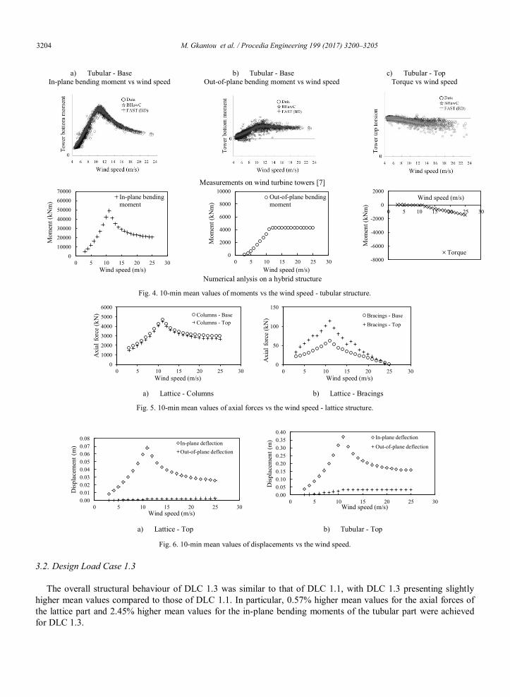
In order to evaluate the structural response, the mean values of the elemental forces and the nodal displacements are calculated and plotted against the wind speed. The observed response is shown in Figs. 4-6. In particular, Fig. 4 presents the mean values of the induced moments on the tubular structure for increasing wind speed. In order to verify the results, the data from measurements on a tubular structure [7] are shown for comparison purposes. Even though the measurements refer to a different, still comparable, support structure, the similarity on the observed response is evident. For in-plane bending moments, peak values are achieved for wind speed 11 m/s. This is related with the pitch controller that decreases the angle of attack in order to mitigate the excitation load on the blade structure and keep the RPM and the power output constant. The influence of the aforementioned effect is less significant on the out-of-plane and torsional moments, which remain relatively stable for wind speeds higher than 11 m/s. The axial forces of the columns and the bracings of the lattice structure for increasing wind speed are depicted in Fig. 5. An ascending curve for wind speed 3-11 m/s and a descending curve for wind speed 11-25 m/s are again noticeable. The axial forces are similar in the lower and the upper part of the lattice columns, justifying the selection of the same cross-section. In addition to the elemental forces, the mean values of the attained displacements at the top of the tubular and the lattice structure are shown in Fig. 6. Peak values of 0.07 m and 0.37 m have been found for the in-plane deflections at the top of the lattice and the tubular structure respectively. The attained values can be utilised for serviceability limit state verifications.
3204 M. Gkantou et al. / Procedia Engineering 199 (2017) 3200–3205 Author name / Procedia Engineering 00 (2017) 000–000 5
a) Tubular - Base
In-plane bending moment vs wind speed b) Tubular - Base
Out-of-plane bending moment vs wind speed c) Tubular - Top
Torque vs wind speed
Measurements on wind turbine towers [7]
Numerical anlysis on a hybrid structure
Fig. 4. 10-min mean values of moments vs the wind speed - tubular structure.
a) Lattice - Columns b) Lattice - Bracings
Fig. 5. 10-min mean values of axial forces vs the wind speed - lattice structure.
a) Lattice - Top b) Tubular - Top
Fig. 6. 10-min mean values of displacements vs the wind speed.
3.2. Design Load Case 1.3
The overall structural behaviour of DLC 1.3 was similar to that of DLC 1.1, with DLC 1.3 presenting slightly higher mean values compared to those of DLC 1.1. In particular, 0.57% higher mean values for the axial forces of the lattice part and 2.45% higher mean values for the in-plane bending moments of the tubular part were achieved for DLC 1.3.
0
10000
20000
3000040000
50000
60000
70000
0 5 10 15 20 25 30
Mom
ent (
kNm
)
Wind speed (m/s)
In-plane bendingmoment
0
2000
4000
6000
8000
10000
0 5 10 15 20 25 30
Mom
ent (
kNm
)
Wind speed (m/s)
Out-of-plane bendingmoment
-8000
-6000
-4000
-2000
0
2000
0 5 10 15 20 25 30
Mom
ent (
kNm
)
Wind speed (m/s)
Torque
0
1000
2000
3000
4000
5000
6000
0 5 10 15 20 25 30
Axi
al fo
rce
(kN
)
Wind speed (m/s)
Columns - BaseColumns - Top
0
50
100
150
0 5 10 15 20 25 30
Axi
al fo
rce
(kN
)
Wind speed (m/s)
Bracings - BaseBracings - Top
0.000.010.020.030.040.050.060.070.08
0 5 10 15 20 25 30
Disp
lace
men
t (m
)
Wind speed (m/s)
In-plane deflectionOut-of-plane deflection
0.000.050.100.150.200.250.300.350.40
0 5 10 15 20 25 30
Disp
lace
men
t (m
)
Wind speed (m/s)
In-plane deflection
Out-of-plane deflection
M. Gkantou et al. / Procedia Engineering 199 (2017) 3200–3205 3205 Author name / Procedia Engineering 00 (2017) 000–000 5
a) Tubular - Base
In-plane bending moment vs wind speed b) Tubular - Base
Out-of-plane bending moment vs wind speed c) Tubular - Top
Torque vs wind speed
Measurements on wind turbine towers [7]
Numerical anlysis on a hybrid structure
Fig. 4. 10-min mean values of moments vs the wind speed - tubular structure.
a) Lattice - Columns b) Lattice - Bracings
Fig. 5. 10-min mean values of axial forces vs the wind speed - lattice structure.
a) Lattice - Top b) Tubular - Top
Fig. 6. 10-min mean values of displacements vs the wind speed.
3.2. Design Load Case 1.3
The overall structural behaviour of DLC 1.3 was similar to that of DLC 1.1, with DLC 1.3 presenting slightly higher mean values compared to those of DLC 1.1. In particular, 0.57% higher mean values for the axial forces of the lattice part and 2.45% higher mean values for the in-plane bending moments of the tubular part were achieved for DLC 1.3.
0
10000
20000
3000040000
50000
60000
70000
0 5 10 15 20 25 30
Mom
ent (
kNm
)
Wind speed (m/s)
In-plane bendingmoment
0
2000
4000
6000
8000
10000
0 5 10 15 20 25 30
Mom
ent (
kNm
)
Wind speed (m/s)
Out-of-plane bendingmoment
-8000
-6000
-4000
-2000
0
2000
0 5 10 15 20 25 30
Mom
ent (
kNm
)
Wind speed (m/s)
Torque
0
1000
2000
3000
4000
5000
6000
0 5 10 15 20 25 30
Axi
al fo
rce
(kN
)
Wind speed (m/s)
Columns - BaseColumns - Top
0
50
100
150
0 5 10 15 20 25 30
Axi
al fo
rce
(kN
)
Wind speed (m/s)
Bracings - BaseBracings - Top
0.000.010.020.030.040.050.060.070.08
0 5 10 15 20 25 30
Disp
lace
men
t (m
)
Wind speed (m/s)
In-plane deflectionOut-of-plane deflection
0.000.050.100.150.200.250.300.350.40
0 5 10 15 20 25 30
Disp
lace
men
t (m
)
Wind speed (m/s)
In-plane deflection
Out-of-plane deflection
6 Gkantou et al./ Procedia Engineering 00 (2017) 000–000
3.3. Design Load Case 6.1
For DLC 6.1, the feathered blade condition together with typical instant aerodynamic forces is illustrated in Fig. 7(a). In Fig. 7(b) a representative load table referring to the top of the tubular part is depicted, with the coordinate system as defined in [3]. The diagonal of the table corresponds to the maximum recorded values during the 600s simulations; vertically the rest elemental forces at the same increment are included. Note that similar load matrices with maxima and minima have been formed for all the parts of the hybrid structure and for all the considered load cases. These can be subsequently used for the extreme load assessment for a certain cross-section at different heights.
a) Feathered blades b) Typical load table (maxima) Fig. 7. Design load case 6.1.
4. Conclusions
A numerical study on a hybrid wind turbine tower has been carried out. The extracted power output for increasing wind speed was compared with findings in [6], presenting similar response. The observed structural behavior of the hybrid tower was studied in line with measurements on a tubular wind turbine tower [7], finding comparable trend with respect to the wind speed. For the in-plane bending moments of the tubular part, the axial forces of the lattice part and the in-plane deflections of the whole structure, mean peak values were achieved for wind speed 11 m/s. The obtained results of the three considered load cases and the generated load tables with maxima and minima of the elemental forces can be used for further assessment of the wind structure’s behaviour, including components’ checks and limit state verifications. Further research could be realised to investigate optimal configurations of hybrid structures, compare them with conventional wind turbine towers and assess the possibility of applying higher steel grades in highly stressed regions.
Acknowledgements
The research leading to these results has received funding from the Research Fund for Coal and Steel (RFCS) under grant agreement RFSR-CT-2015-00021.
References
[1] International Electrotechnical Commission, 2005. IEC 61400-1: Wind turbines Part 1: Design requirements. International Electrotechnical Commission.
[2] Rebelo, C. and Mohammadi, M., 2016. Steel Hybrid Onshore Wind Towers Installed with Minimal Effort, RFCS Project Report. Deliverable D1.1.
[3] Ashes 2.2.3, Simis, 2017. Available from http://www.simis.io/. [Accessed 7 January 2017]. [4] TurbSim, NWTC Information Portal, 2017. Available from https://nwtc.nrel.gov/TurbSim. [Accessed 7 January 2017]. [5] Jonkman, J., Butterfield, S., Musial, W. and Scott, G., 2009. Definition of a 5-MW reference wind turbine for offshore system development.
National Renewable Energy Laboratory, Golden, CO, Technical Report No. NREL/TP-500-38060. [6] Kim, T., Larsen, T.J. and Yde, A., 2015. Investigation of potential extreme load reduction for a two‐bladed upwind turbine with partial pitch.
Wind Energy, 18(8), pp.1403-1419. [7] Guntur, S., Jonkman, J.M., Jonkman, B., Wang, Q., Sprague, M.A., Hind, M., Sievers, R. and Schreck, S.J., 2016. FAST v8 Verification and
Validation for a MW-scale Wind Turbine with Aeroelastically Tailored Blades. In 34th Wind Energy Symposium (p. 1008).