11th World Congress on Computational Mechanics (WCCM XI) 5th European Conference on Computational Mechanics (ECCM V) 6th European Conference on Computational Fluid Dynamics (ECFD VI) E. O˜ nate, J. Oliver and A. Huerta (Eds) ON THE USAGE OF FINITE DIFFERENCES FOR THE DEVELOPMENT OF DISCRETE LINEARISED AND ADJOINT CFD SOLVERS ANNA ENGELS-PUTZKA, JAN BACKHAUS, CHRISTIAN FREY German Aerospace Center (DLR), Institute of Propulsion Technology Linder H¨ ohe, 51147 Cologne, Germany e-mail: [email protected], [email protected], [email protected]Key words: Time-linearised Methods, Adjoint Methods, Finite Differences, Algorithmic Differentiation Abstract. In this paper we discuss the usage of finite differences for the computation of the flux Jacobian in the framework of a discrete adjoint or time-linearised flow solver, in particular the associated choice of an appropriate step size. For comparison, we apply algorithmic differentiation to obtain an exact flux Jacobian. It turns out that the results depend strongly on the choice of the slope limiter. A careful choice of this function is crucial for computations with exact flux linearisations as well as for finite difference approximations. 1 INTRODUCTION For many applications of computational fluid dynamics, adjoint and linear methods nowadays play an important role. The adjoint method [1, 2] is for example used to efficiently compute sensitivities for large numbers of free parameters, e.g. for optimisation problems (see e.g. [3]). Time-linearised methods can be used as an efficient approximation to unsteady simulations for applications e.g. in aeroelasticity and aeroacoustics. There are two basic approaches for the development of adjoint methods. Either, ad- joint differential equations can be derived and then discretised and solved (“continuous adjoint”), or the adjoint equations can be derived from the discretised flow equations (“discrete adjoint”). A discussion of both approaches can be found for example in [4]. In this work we focus on discrete adjoint methods. One advantage of these is that it is easier to obtain an adjoint solver which is consistent with the underlying nonlinear solver, which is an important issue for the accuracy of the adjoint sensitivities. A central ingredient for the development of discrete adjoint flow solvers is the com- putation of the flux Jacobian, i.e. the derivatives of the numerical flux functions with respect to the flow variables, which can be obtained in different ways. An overview and 1
Transcript
11th World Congress on Computational Mechanics (WCCM XI)5th European Conference on Computational Mechanics (ECCM V)
6th European Conference on Computational Fluid Dynamics (ECFD VI)E. Onate, J. Oliver and A. Huerta (Eds)
ON THE USAGE OF FINITE DIFFERENCES FOR THEDEVELOPMENT OF DISCRETE LINEARISED AND
ADJOINT CFD SOLVERS
ANNA ENGELS-PUTZKA, JAN BACKHAUS, CHRISTIAN FREY
German Aerospace Center (DLR), Institute of Propulsion TechnologyLinder Hohe, 51147 Cologne, Germany
Abstract. In this paper we discuss the usage of finite differences for the computationof the flux Jacobian in the framework of a discrete adjoint or time-linearised flow solver,in particular the associated choice of an appropriate step size. For comparison, we applyalgorithmic differentiation to obtain an exact flux Jacobian. It turns out that the resultsdepend strongly on the choice of the slope limiter. A careful choice of this functionis crucial for computations with exact flux linearisations as well as for finite differenceapproximations.
1 INTRODUCTION
For many applications of computational fluid dynamics, adjoint and linear methodsnowadays play an important role. The adjoint method [1, 2] is for example used toefficiently compute sensitivities for large numbers of free parameters, e.g. for optimisationproblems (see e.g. [3]). Time-linearised methods can be used as an efficient approximationto unsteady simulations for applications e.g. in aeroelasticity and aeroacoustics.
There are two basic approaches for the development of adjoint methods. Either, ad-joint differential equations can be derived and then discretised and solved (“continuousadjoint”), or the adjoint equations can be derived from the discretised flow equations(“discrete adjoint”). A discussion of both approaches can be found for example in [4].In this work we focus on discrete adjoint methods. One advantage of these is that it iseasier to obtain an adjoint solver which is consistent with the underlying nonlinear solver,which is an important issue for the accuracy of the adjoint sensitivities.
A central ingredient for the development of discrete adjoint flow solvers is the com-putation of the flux Jacobian, i.e. the derivatives of the numerical flux functions withrespect to the flow variables, which can be obtained in different ways. An overview and
1
Anna Engels-Putzka, Jan Backhaus and Christian Frey
discussion of various differentiation methods is given in [5]. In principle it is possible todifferentiate the flux functions analytically “by hand”, but this is a very challenging task[6]. Alternatively, finite differences can be used to obtain the derivatives in a “black-box”manner. The main problem with this approach is the choice of an appropriate step sizefor the finite differences. It should be small to minimise the approximation error but itmust not be too small in order to avoid cancellation errors. Another possibility is to useof algorithmic (sometimes also called automatic) differentiation (AD) [7]. This has beendone e.g. by Mader et al. [8, 9] and Courty et al. [10].
Within the flow solver TRACE, adjoint [11, 12] and time-linearised [13, 14] methodshave been developed since 2006 using the discrete approach. Since an analytical differ-entiation “by hand” would be impratical for an industrially used, complex flow solver,which is constantly developed, finite differences are used for the computation of the fluxJacobian. Additionally we have now, based on the work described in [15], implemented aversion which makes use of algorithmic differentiation.
We discuss both variants in section 2.2. Before, in section 2.1 we summarise importantproperties of the underlying nonlinear solver. In particular we discuss the implementationand properties of various limiter functions. In section 3 we present numerical exampleswhere we apply these limiter functions in combination with different linearisation methods,i.e. algorithmic differentiation and finite differences with different step sizes. Finally, insection 4 we summarise our results and draw some conclusions.
2 THEORY
The flow solver TRACE has been constantly developed for more than twenty yearsand offers many different solver modes and features for the simulation of turbomachineryflows [16, 17]. We discuss here briefly those features which are relevant for the currentstudy.
2.1 Nonlinear flow solver
TRACE is a hybrid-grid cell-centered finite volume solver. In the steady nonlinearmode, the Reynolds-averaged Navier–Stokes equations are solved using a time-marchingalgorithm. Time integration and spatial discretisation are separated. Since the adjointsolver is so far only available on structured grids, we concentrate on the spatial discreti-sation for structured grids.
The convective fluxes at the cell interfaces are approximated using the Roe scheme [18].The so-called Roe-averaged variables are computed from left and right states qL
i+ 12
, qRi+ 1
2
.
Using MUSCL extrapolation [19], these are given by
Anna Engels-Putzka, Jan Backhaus and Christian Frey
To avoid oscillations in the numerical solutions, the corrections ∆qL,∆qR are modifiedby multiplying the state differences by appropriate slope limiters:
qLi+ 1
2= qi + 1
2∆q
L
= qi + 14
[(1− κ)ϕ
(r+i− 1
2
)(qi − qi−1) + (1 + κ)ϕ
(r−i+ 1
2
)(qi+1 − qi)
](3)
qRi+ 1
2= qi+1 − 1
2∆q
R
= qi+1 − 14
[(1 + κ)ϕ
(r+i+ 1
2
)(qi+1 − qi) + (1− κ)ϕ
(r−i+ 3
2
)(qi+2 − qi+1)
], (4)
where we use the following ratios of differences:
r+i+ 1
2
=qi+2 − qi+1
qi+1 − qi, r−
i+ 12
=qi − qi−1qi+1 − qi
, r+i− 1
2
=qi+1 − qiqi − qi−1
, r−i+ 3
2
=qi+1 − qiqi+2 − qi+1
. (5)
Considering for the moment only the left state, we can rearrange
∆qL
= 12
[(1− κ)ϕ
(r+i− 1
2
)+ (1 + κ)ϕ
(1
r+i− 1
2
)r+i− 1
2
](qi − qi−1). (6)
If the limiter function ϕ has the symmetry property
ϕ
(1
r
)=ϕ(r)
r(7)
equation (6) simplifies to ∆qL
= ϕ(r+i− 1
2
)(qi− qi−1), i.e. the correction is independent of
κ and we haveqLi+ 1
2= qi + 1
2ϕ(r+i− 1
2
)(qi − qi−1). (8)
Analogous transformations can be applied for qRi+ 1
2
.
We consider the following choices for the limiter function ϕ which fulfill the symmetrycondition (7):
Minmod ϕ(r) = minmod(1, r) =
0 r < 0
r 0 ≤ r ≤ 1
1 r > 1
van Albada ϕ(r) =
0 r < 0r2 + r
r2 + 1r ≥ 0
van Leer ϕ(r) =r + |r|1 + |r|
=
{0 r < 02r1+r
r ≥ 0
3
Anna Engels-Putzka, Jan Backhaus and Christian Frey
All these limiters also have the so-called TVD (total variation diminishing) property [21].Another possible symmetry property for limiter functions is
ϕ
(1
r
)= ϕ(r) (9)
(which applies in particular to constant functions, i.e. if no limiter is used). Then (6) canbe written as
∆qL
= 12
[(1− κ) + (1 + κ)r+
i− 12
]ϕ(r+i− 1
2
)(qi − qi−1) (10)
= 12
[(1− κ)(qi − qi−1) + (1 + κ)(qi+1 − qi)]ϕ(r+i− 1
2
). (11)
One possible function with this property is
ϕ(r) =2r
r2 + 1, (12)
cf. for example [20]. This function does not behave well if both the numerator andthe denominator of r approach zero. This can be changed if the limiter function isreformulated in terms of these differences δq+, δq− and an additional constant is added tonumerator and denominator of the resulting function:
ϕ(δq+, δq−) =2δq+δq− + εvA
(δq+)2 + (δq−)2 + εvA. (13)
Such a limiter formulation is used for example by Anderson et al. [22] and Benetschik andGallus [23]. We use in this study a further modification by applying (13) to (δq+)2, (δq−)2.We refer to this as a “van Albada type” limiter. Note that this limiter function does notvanish if δq+ and δq− have different signs, so in particular it does not have the TVDproperty. Enforcing the TVD property would prevent the differentiability near zero [23].
All other limiters are implemented as stated above, except that the denominator ofthe ratio r is prevented from becoming exactly zero by adding an offset of 10−8 (withappropriate sign). Equations (3) and (4) are implemented componentwise for primitivevariables in absolute frame of reference.
2.2 Discrete linearised and adjoint solver
We consider the linearisation of the discrete equation R(q, x) = 0, where q denotes asbefore the flow state (solution) and x represents the computational grid. The residual incell i is given by
Ri = V −1i
∑σ∈∂i
Fσ − Si, (14)
4
Anna Engels-Putzka, Jan Backhaus and Christian Frey
where Vi denotes the cell volume, σ runs over the faces of cell i and Fσ represents thenumerical flux through the face σ, which depends of course on the employed discretisa-tion scheme. Si stands here for the rotational source terms which appear since the flowequations are formulated in the relative frame of reference.
The Jacobian ∂R∂q
therefore consists of two contributions, the flux Jacobian and thesource term Jacobian. While the latter can be relatively easily derived and implementedfor rotational source terms, the former would be very difficult to treat explicitly. There-fore, in the current implementation the derivatives of the fluxes are approximated by finitedifferences. Different levels of accuracy can be chosen for the finite differences, we discusshere only the (default) case of second order central differences, i.e. we have for each flowcomponent qj:
∂Fσ
∂qji≈ F (q + δqji )− F (q − δqji )
2δqji. (15)
The perturbation amplitude δqji is determined as
δqji = (|qji |+ µ)ε (16)
where µ and ε are parameters which have to be chosen appropriately. The perturbationis basically proportional to the magnitude of the respective flow component with the stepsize ε as proportionality factor, while the threshold µ prevents the perturbation frombecoming too small for very small flow components.
As a benchmark to assess the accuracy of the finite differences we apply algorithmicdifferentiation to obtain an exact version of the flux Jacobian. For this we use the ADtool ADOL-C [24], which employs the operator overloading technique, in forward modeand simply replace the finite differences in the computation of the flux Jacobian by algo-rithmically differentiated routines. For technical details on the usage of AD in TRACEwe refer to [15]. The rest of the solver remains unchanged, in particular we use the samesolution algorithm – a preconditioned GMRes algorithm with restarts – for the resultinglinear equation system as in the finite difference case.
3 APPLICATION
3.1 Numerical test case: wave propagation
The linear solver is used to simulate the propagation of an acoustic wave through anannular duct. In this case the steady state at which the flow equations are linearised isjust a constant flow state. The frequency of the wave can be varied to simulate differentgrid resolutions (in relation to the wave length). We use four different frequencies, namely1250 Hz, 2500 Hz, 5000 Hz, and 10000 Hz. An example of the resulting solutions is shownin Fig. 1.
Ideally, the wave should pass the duct unchanged, but in practice the numerical solutionintroduces a certain amount of dissipation, i.e. the amplitude of the waves decreasestowards the end of the duct. This numerical dissipation rate is given by
5
Anna Engels-Putzka, Jan Backhaus and Christian Frey
D = 1−(|∆pout||∆pmax|
)λl
, (17)
where λ is the wave length and l the length of the duct.We vary the step size for the finite differences between 10−1 and 10−4, which is still large
enough to avoid cancellation effects. To keep the number of computations manageable, wedo not vary the size of the threshold µ independently, but set always µ = ε. The resultsare compared to those obtained using algorithmic differentiation. Moreover, differentlimiter setups are used. For comparison, we also carried out a simulation with first orderspatial accuracy. In this case the differentiation method does not influence the results.
Exemplary results are shown in Figures 2 and 3. In Fig. 2 we compare the variousdifferentiation methods for selected limiters, while in Fig. 3 we keep the differentiationfixed and vary the limiter.
We see that if no limiter is used, the numerical dissipation shows a second order decay,and it is relatively independent of the differentiation parameters. Only for ε = 10−1 asmall deviation can be observed. In contrast, when using the Minmod limiter, the dissi-pation values are the same as in the first order case for all finite difference computations.Algorithmic differentiation yields only slightly better results, which are still far from bee-ing second order accurate. The limiters van Albada and van Leer show a very similarbehaviour (compare Fig. 3).
For the case of finite differences, this can be explained as follows: Since the state qat which the Jacobian is computed is constant, i.e. qi = q for all i, if we evaluate theextrapolated states qL
i+ 12
, qRi+ 1
2
starting from a state in which only one component in one
cell is perturbed by ∆qji , the correction terms ∆qL, ∆q
Rin eqns. (3), (4) are always zero
(since either r ≤ 0 and therefore ϕ(r) = 0, or the state difference is zero) and so theextrapolation reduces to a first order scheme.
Figure 1: Solution produced by the linear solver for the propagation of a wave with a frequency of5000 Hz using the following setting: second order spatial discretisation, van Albada type limiter withεvA = 10−4, step size ε = 10−2 for finite differences.
6
Anna Engels-Putzka, Jan Backhaus and Christian Frey
101 102
Cells per Wave Length
10-4
10-3
10-2
10-1
100
Numerical Dissipa
tion
1st order2nd ord., Lim. off, ε=10−1
2nd ord., Lim. off, ε=10−2
2nd ord., Lim. off, ε=10−3
2nd ord., Lim. off, ε=10−4
2nd ord., Lim. off, alg. diff.
101 102
Cells per Wave Length
10-4
10-3
10-2
10-1
100
Numerical Dissipa
tion
1st order2nd ord., Minmod, ε=10−1
2nd ord., Minmod, ε=10−2
2nd ord., Minmod, ε=10−3
2nd ord., Minmod, ε=10−4
2nd ord., Minmod, alg. diff.
101 102
Cells per Wave Length
10-4
10-3
10-2
10-1
100
Numerical Dissipatio
n
1st order2nd ord., v. Alb. t., ε=10−1
2nd ord., v. Alb. t., ε=10−2
2nd ord., v. Alb. t., ε=10−3
2nd ord., v. Alb. t., ε=10−4
2nd ord., v. Alb. t., alg. diff.
101 102
Cells per Wave Length
10-4
10-3
10-2
10-1
100Nu
merical Dissipatio
n
1st order2nd ord., v. Alb. t., ε=10−1
2nd ord., v. Alb. t., ε=10−2
2nd ord., v. Alb. t., ε=10−3
2nd ord., v. Alb. t., ε=10−4
2nd ord., v. Alb. t., alg. diff.
Figure 2: Comparison of numerical dissipation curves using different differentiation methods for fourlimiter settings: limiter off (top left), Minmod (top right), van Albada type with εvA = 10−4 (bottomleft) , van Albada type with εvA = 10−8 (bottom right). For comparison, the first order curve is alsoshown in each plot.
The van Albada type limiter yields always the second order curve if algorithmic dif-ferentiation is used, while for finite differences the behaviour depends on the value of theconstant εvA. For εvA = 10−4 only the largest step size ε = 10−1 leads to worse results(see bottom left plot in Fig. 2), for εvA = 10−8 a step size of (at most) ε = 10−3 is neededto keep the second order decay. An analysis shows that the relevant quantity is the ratioε4
εvA. If this is small (about 10−2 or smaller), the finite differences are very similar to the
case where no limiter is used, if it is large (about 102 or greater), the extrapolation schemereduces effectively to first order.
7
Anna Engels-Putzka, Jan Backhaus and Christian Frey
101 102
Cells per Wave Length
10-4
10-3
10-2
10-1
100
Num
eric
al D
issi
patio
n
2nd ord., Lim. off, alg. diff.2nd ord., Minmod, alg. diff.2nd ord., v. Leer, alg. diff.2nd ord., v. Alb., alg. diff.2nd ord., v. Alb. t., alg. diff.
101 102
Cells per Wave Length
10-4
10-3
10-2
10-1
100
Num
eric
al D
issi
patio
n
2nd ord., Lim. off, ε=10−2
2nd ord., Minmod, ε=10−2
2nd ord., v. Leer, ε=10−2
2nd ord., v. Alb., ε=10−2
2nd ord., v. Alb. t., ε=10−2
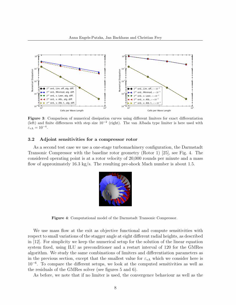
Figure 3: Comparison of numerical dissipation curves using different limiters for exact differentiation(left) and finite differences with step size 10−2 (right). The van Albada type limiter is here used withεvA = 10−4.
3.2 Adjoint sensitivities for a compressor rotor
As a second test case we use a one-stage turbomachinery configuration, the DarmstadtTransonic Compressor with the baseline rotor geometry (Rotor 1) [25], see Fig. 4. Theconsidered operating point is at a rotor velocity of 20,000 rounds per minute and a massflow of approximately 16.3 kg/s. The resulting pre-shock Mach number is about 1.5.
Figure 4: Computational model of the Darmstadt Transonic Compressor.
We use mass flow at the exit as objective functional and compute sensitivities withrespect to small variations of the stagger angle at eight different radial heights, as describedin [12]. For simplicity we keep the numerical setup for the solution of the linear equationsystem fixed, using ILU as preconditioner and a restart interval of 120 for the GMResalgorithm. We study the same combinations of limiters and differentiation parameters asin the previous section, except that the smallest value for εvA which we consider here is10−6. To compare the different setups, we look at the computed sensitivities as well asthe residuals of the GMRes solver (see figures 5 and 6).
As before, we note that if no limiter is used, the convergence behaviour as well as the
8
Anna Engels-Putzka, Jan Backhaus and Christian Frey
Time step
Re
sid
ua
l (L
2)
0 500 1000 1500 2000
106
105
104
103
102
101
100
Limiter off, = 101
Limiter off, = 102
Limiter off, = 103
Limiter off, = 104
Limiter off, alg. diff.
Parameter indexm
[k
g/s
]
0 1 2 3 4 5 6 70
0.001
0.002
0.003
0.004
0.005
0.006
0.007
0.008
0.009
Limiter off, = 101
Limiter off, = 102
Limiter off, = 103
Limiter off, = 104
Limiter off, alg. diff.
.
Time step
Re
sid
ua
l (L
2)
0 200 400 600 800 1000
106
105
104
103
102
101
100
Minmod, = 101
Minmod, = 102
Minmod, = 103
Minmod, = 104
Minmod, alg. diff.
Parameter index
m [
kg
/s]
0 1 2 3 4 5 6 70
0.001
0.002
0.003
0.004
0.005
0.006
0.007
0.008
0.009
Minmod, = 101
Minmod, = 102
Minmod, = 103
Minmod, = 104
Minmod, alg. diff.
.
Time step
Re
sid
ua
l (L
2)
0 200 400 600 800 1000
106
105
104
103
102
101
100
van Albada type, = 101
van Albada type, = 102
van Albada type, = 103
van Albada type, = 104
van Albada type, alg. diff.
Parameter index
m [
kg
/s]
0 1 2 3 4 5 6 70
0.001
0.002
0.003
0.004
0.005
0.006
0.007
0.008
0.009
van Albada type, = 101
van Albada type, = 102
van Albada type, = 103
van Albada type, = 104
van Albada type, alg. diff.
.
Figure 5: Comparison of convergence behaviour (left) and sensitivities (right) using different differ-entiation methods for three limiter settings: limiter off (top), Minmod (mid), van Albada type withεvA = 10−4 (bottom).
9
Anna Engels-Putzka, Jan Backhaus and Christian Frey
Time step
Re
sid
ua
l (L
2)
0 500 1000 1500 2000
106
105
104
103
102
101
100
Limiter off, alg. diff.
Minmod, alg. diff.
van Albada, alg. diff.
van Leer, alg. diff.
v. Alb. t., vA
= 104, alg. diff.
v. Alb. t., vA
= 105, alg. diff.
v. Alb. t., vA
= 106, alg. diff.
Parameter indexm
[k
g/s
]
0 1 2 3 4 5 6 70
0.001
0.002
0.003
0.004
0.005
0.006
0.007
0.008
0.009Limiter off, alg. diff.
Minmod, alg. diff.
van Albada, alg. diff.
van Leer, alg. diff.
v. Alb. t., vA
= 104, alg. diff.
v. Alb. t., vA
= 105, alg. diff.
v. Alb. t., vA
= 106, alg. diff.
.
Time step
Re
sid
ua
l (L
2)
0 500 1000 1500 2000
106
105
104
103
102
101
100
Limiter off, = 102
Minmod, = 102
van Albada, = 102
van Leer, = 102
v. Alb. t., vA
= 104, = 10
2
v. Alb. t., vA
= 105, = 10
2
v. Alb. t., vA
= 106, = 10
2
Parameter index
m [
kg
/s]
0 1 2 3 4 5 6 70
0.001
0.002
0.003
0.004
0.005
0.006
0.007
0.008
0.009Limiter off, = 10
2
Minmod, = 102
van Albada, = 102
van Leer, = 102
v. Alb. t., vA
= 104, = 10
2
v. Alb. t., vA
= 105, = 10
2
v. Alb. t., vA
= 106, = 10
2
.
Figure 6: Comparison of convergence behaviour (left) and sensitivities (right) using different limitersfor exact differentiation (top) and finite differences with step size 10−2 (bottom).
sensitivities depend hardly on the differentiation method. The van Albada type limiterbehaves quite similarly, except that the differences between ε = 10−1 and the othercases are a bit larger. But it can also be seen that for all differentiation methods theconvergence is much faster than without limiter. The results for the Minmod limiterdepend more strongly on the differentiation method. In particular, for finite differenceswith step size 10−4 and for algorithmic differentiation the GMRes algorithm does notconverge any more. Therefore, the computed sensitivities are of no use in these cases.
Figure 6 shows that the other limiters (van Albada, van Leer), and also the van Albadatype limiter with εvA < 10−4 have similar problems in the case of exact differentiation.In principle, the same applies to the finite difference results, although the minimal stepsize for which the computation converges at all depends on the choice of the limiter. Forthe cases with convergence problems, different combinations of preconditioner and restart
10
Anna Engels-Putzka, Jan Backhaus and Christian Frey
interval, e.g. ILU with increased level of fill-in and restart interval 300, did not improvethe convergence behaviour significantly.
We also see in Fig. 6 that for a given differentiation method the resulting sensitivitiesdepend – in some cases very strongly – on the limiter used, even if all solutions areconverged equally well. This is of course not very surprising, since also the steady andthe adjoint solution change considerably when a different limiter is used. The very largedeviation for the first parameter in the case where no limiter is used is due to significantdifferences in the adjoint solution near the hub, which do not have a counterpart in thesteady solution and have to be further investigated.
4 CONCLUSION
We have shown that it is possible to construct the flux Jacobian for a discrete adjointor linear solver using finite differences, but the choice of the limiter function is a verycritical point for any discrete linearisation. On the other hand, if no limiter is used, theconvergence of the nonlinear and the linear/adjoint solvers becomes considerably slower.For a scheme without limiter as well as for an appropriate choice of the limiter function(van Albada type), the computations based on finite differences become nearly identicalto those with the “exact” flux Jacobian (computed using algorithmically differentiatedroutines) if the step size is chosen sufficiently small. In the examples considered, “suffi-ciently small” means in the order of 10−3 to 10−4, and already for a step size of 10−2 theresulting sensitivities and numerical dissipation rates are very close to the AD reference.However, for many choices of the limiter functions, in particular for all considered TVDlimiters, the behaviour of the linearization is problematic. For the “numerical dissipation”test case the accuracy reduces to first order in these cases. For the compressor test case,the linear system based on the exact linearisation or finite differences with small step sizebecomes very stiff so that the GMRes algorithm does not converge any more or only veryslowly. The reason for this has to be studied in more detail. We have also seen that thebehaviour of the van Albada type limiter is very sensitive with respect to the choice ofthe constant εvA.
Acknowledgements Financial support by MTU Aero Engines (co-sponsorsip of the firstauthor) and the German Ministry of Economy and Energy (Project R&E TURB, project number20T1104B) is gratefully acknowledged.
REFERENCES
[1] A. Jameson, “Aerodynamic design via control theory,” Journal of Scientific Computing,vol. 3, no. 3, pp. 233–260, 1988.
[2] M. B. Giles and N. A. Pierce, “An introduction to the adjoint approach to design,” Flow,Turbulence and Combustion, vol. 65, pp. 393–415, 2000.
11
Anna Engels-Putzka, Jan Backhaus and Christian Frey
[3] J. E. V. Peter and R. P. Dwight, “Numerical sensitivity analysis for aerodynamic optimiza-tion: A survey of approaches,” Computers & Fluids, vol. 39, no. 3, pp. 373–391, 2010.
[4] K. C. Giannakoglou and D. I. Papadimitriou, “Adjoint methods for shape optimization,”in Optimization and Computational Fluid Dynamics (G. Janiga and D. Thevenin, eds.),Springer, 2008.
[5] J. R. R. A. Martins and J. T. Hwang, “Review and unification of methods for computingderivatives of multidisciplinary computational models,” AIAA Journal, vol. 51, pp. 2582–2599, November 2013.
[6] M. B. Giles, M. C. Duta, and N. A. Pierce, “Algorithm developments for discrete adjointmethods,” AIAA J., vol. 41, no. 2, pp. 198–205, 2003.
[7] A. Griewank, Evaluating Derivatives, Principles and Techniques of Algorithmic Differenti-ation. Philadelphia: SIAM, 2000.
[8] A. C. Marta, C. A. Mader, J. R. R. A. Martins, E. Van der Weide, and J. J. Alonso, “Amethodology for the development of discrete adjoint solvers using automatic differentiationtools,” Int. J. Comput. Fluid D., vol. 21, no. 9-10, pp. 307–327, 2007.
[9] C. A. Mader, J. R. R. A. Martins, J. J. Alonso, and E. van der Weide, “ADJoint: Anapproach for the rapid development of discrete adjoint solvers,” AIAA JOURNAL, vol. 46,pp. 863–873, APR 2008. AIAA/ISSMO 11th Multidisciplinary Analysis and OptimizationConference, Portsmouth, VA, SEP 06-08, 2006.
[10] F. Courty, A. Dervieux, B. Koobus, and L. Hascoet, “Reverse automatic differentiationfor optimum design: from adjoint state assembly to gradient computation,” OptimizationMethods and Software, vol. 18, no. 5, pp. 615–627, 2003.
[11] C. Frey, D. Nurnberger, and H.-P. Kersken, “The discrete adjoint of a turbomachineryRANS solver,” in Proceedings of ASME-GT2009, 2009.
[12] C. Frey, G. Ashcroft, J. Backhaus, E. Kugeler, and J. Wellner, “Adjoint-based flow sensi-tivity analyis using arbitrary control surfaces,” in Proceedings of ASME-GT2011, 2011.
[13] H.-P. Kersken, C. Frey, C. Voigt, and G. Ashcroft, “Time-Linearized and Time-Accurate3D RANS Methods for Aeroelastic Analysis in Turbomachinery,” J. Turbomach., vol. 134,no. 5, 2012.
[14] C. Frey, G. Ashcroft, H.-P. Kersken, and C. Weckmuller, “Advanced numerical methodsfor the prediction of tonal noise in turbomachinery — Part II: Time-linearized methods,”Journal of Turbomachinery, vol. 136, no. 2, pp. 021002–021002, 2013.
[15] M. Sagebaum, E. Ozkaya, and N. R. Gauger, “Challenges in the automatic differentiationof an industrial CFD solver,” in Evolutionary and Deterministic Methods for Design, Op-timization and Control with Application to Industrial and Societal Problems (EUROGEN2013), 2013.
12
Anna Engels-Putzka, Jan Backhaus and Christian Frey
[16] D. Nurnberger, F. Eulitz, S. Schmitt, and A. Zachcial, “Recent progress in the numericalsimulation of unsteady viscous multistage turbomachinery flow,” in ISABE 2001-1081,Sept. 2001.
[17] K. Becker, K. Heitkamp, and E. Kugeler, “Recent progress in a hybrid-grid CFD solver forturbomachinery flows,” in Proceedings Fifth European Conference on Computational FluidDynamics ECCOMAS CFD 2010, 2010.
[18] P. L. Roe, “Approximate Riemann solvers, parameter vectors, and difference schemes,”Journal of Computational Physics, vol. 43, no. 2, pp. 357–372, 1981.
[19] B. van Leer, “Towards the ultimate conservative difference scheme. V. a second-order sequelto Godunov’s method,” Journal of Computational Physics, vol. 32, no. 1, pp. 101–136, 1979.
[20] J. Blazek, Computational fluid dynamics: principles and applications. Elsevier Science,2001.
[21] C. Hirsch, Numerical Computation of Internal and External Flows – Computational Meth-ods for Inviscid and Viscous Flows, vol. 2. Wiley, 1 ed., 1990.
[22] W. Anderson, J. Thomas, and B. van Leer, “Comparison of finite volume flux vector split-tings for the Euler equations,” AIAA JOURNAL, vol. 24, pp. 1453–1460, SEP 1986.
[23] H. Benetschik and H. E. Gallus, “Inviscid and viscous transonic flows in cascades using animplicit upwind algorithm,” Journal of Propulsion and Power, vol. 8, no. 2, pp. 403–409,1992.
[24] A. Griewank and A. Walther, “Getting started with ADOL-C,” in Combinatorial ScientificComputing (U. Naumann and O. Schenk, eds.), CRC Press, Taylor and Francis Group,2012.
[25] G. Schulze, D. K. Hennecke, J. Sieber, and B. Wohrl, “Der neue Verdichterprufstand ander TH Darmstadt,” VDI Berichte Nr. 1109, Germany., 1994.