Approved for public release; further dissemination unlimited UCRL-ID-TR-200850 On the Utility of Antiprotons as Drivers for Inertial Confinement Fusion L. John Perkins, Charles D. Orth, Max Tabak – Lawrence Livermore National Laboratory June 15, 2003 Lawrence Livermore National Laboratory U.S. Department of Energy
Transcript
Approved for public release; further dissemination unlimited
UCRL-ID-TR-200850
On the Utility ofAntiprotons as Drivers forInertial ConfinementFusion
L. John Perkins, Charles D. Orth, Max Tabak – LawrenceLivermore National Laboratory
June 15, 2003
LawrenceLivermoreNationalLaboratory
U.S. Department of Energy
DISCLAIMER This document was prepared as an account of work sponsored by an agency of the United StatesGovernment. Neither the United States Government nor the University of California nor any of theiremployees, makes any warranty, express or implied, or assumes any legal liability or responsibility forthe accuracy, completeness, or usefulness of any information, apparatus, product, or process disclosed, orrepresents that its use would not infringe privately owned rights. Reference herein to any specificcommercial product, process, or service by trade name, trademark, manufacturer, or otherwise, does notnecessarily constitute or imply its endorsement, recommendation, or favoring by the United StatesGovernment or the University of California. The views and opinions of authors expressed herein do notnecessarily state or reflect those of the United States Government or the University of California, andshall not be used for advertising or product endorsement purposes. This work was performed under the auspices of the U. S. Department of Energy by the University ofCalifornia, Lawrence Livermore National Laboratory under Contract No. W-7405-Eng-48.
This report has been reproduced directly from the best available copy.
Available to DOE and DOE contractors from the
Office of Scientific and Technical Information P.O. Box 62, Oak Ridge, TN 37831
Prices available from (423) 576-8401 http://apollo.osti.gov/bridge/
Available to the public from the
National Technical Information Service U.S. Department of Commerce
5285 Port Royal Rd., Springfield, VA 22161 http://www.ntis.gov/
OR
Lawrence Livermore National Laboratory
Technical Information Department’s Digital Library http://www.llnl.gov/tid/Library.html
1
On the Utility of Antiprotons as Drivers forInertial Confinement Fusion
L. John Perkins, Charles D. Orth, Max TabakLawrence Livermore National Laboratory
June 15, 2003
Abstract
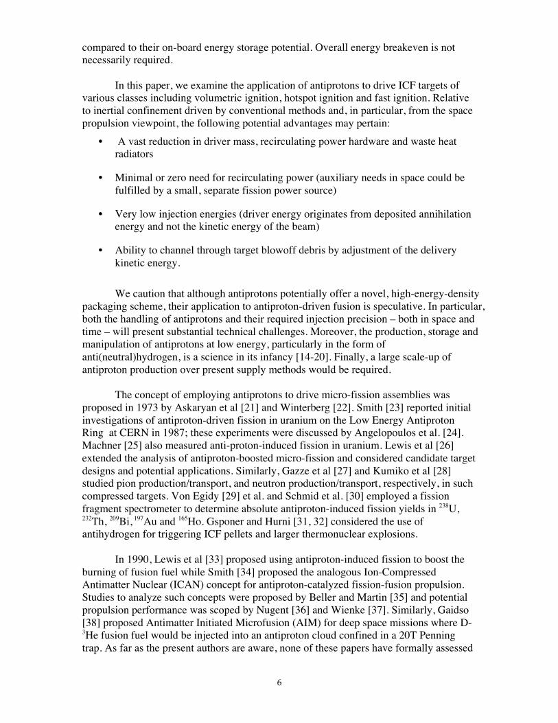
By contrast to the large mass, complexity and recirculating power of conventionaldrivers for inertial confinement fusion (ICF), antiproton annihilation offers a specificenergy of 90MJ/µg and thus a unique form of energy packaging and delivery. Inprinciple, antiproton drivers could provide a profound reduction in system mass foradvanced space propulsion by ICF. We examine the physics underlying the use ofantiprotons ( p) to drive various classes of high-yield ICF targets by the methods ofvolumetric ignition, hotspot ignition and fast ignition. The useable fraction ofannihilation deposition energy is determined for both p-driven ablative compressionand p-driven fast ignition, in association with 0-D and 1-D target burn models.Thereby, we deduce scaling laws for the number of injected antiprotons required percapsule, together with timing and focal spot requirements. The kinetic energy of theinjected antiproton beam required to penetrate to the desired annihilation point isalways small relative to the deposited annihilation energy. We show that heavymetal seeding of the fuel and/or ablator is required to optimize local deposition ofannihilation energy and determine that a minimum of ~3x10¹⁵ injected antiprotonswill be required to achieve high yield (several hundred megajoules) in any targetconfiguration. Target gains – i.e., fusion yields divided by the available p - pannihilation energy from the injected antiprotons (1.88GeV/ p) – range from ~3 forvolumetric ignition targets to ~600 for fast ignition targets. Antiproton-driven ICF isa speculative concept, and the handling of antiprotons and their required injectionprecision – temporally and spatially – will present significant technical challenges.The storage and manipulation of low-energy antiprotons, particularly in the form ofantihydrogen, is a science in its infancy and a large scale-up of antiproton productionover present supply methods would be required to embark on a serious R&Dprogram for this application.
6. ANTIPROTON-DRIVEN FAST IGNITION6.1 Fast Ignition Rationale6.2 Fast Ignition Hotspot Creation6.3 Slow Compression Drive6.4 Fast Ignition Design Point
7. TIMING AND AIMING REQUIREMENTS FOR ANTIPROTON INJECTION
8. ANTIPROTON PRODUCTION, STORAGE AND INJECTION
9. SUMMARY AND CONCLUSIONS
10. REFERENCES
Acknowledgements
The authors take pleasure in acknowledging Jay Polk and Stephanie Leifer ofJPL/NASA for encouraging our explorations in this topic; Gerald Smith, formally ofPennsylvania State University, for directing us to his earlier concepts in the field; DavidMorgan and Mark Herrmann of Lawrence Livermore National Laboratory forinformative discussions on antiproton physics and indirect-drive ICF capsules,respectively.
This work was performed under the auspices of the U. S. Department of Energyby the University of California, Lawrence Livermore National Laboratory, underContract No. W-7405-Eng-48. The research was funded under the Work for OthersProposal #L8750 by the National Aeronautics and Space Administration (NASA) throughthe Jet Propulsion Laboratory (JPL).
4
5
1. INTODUCTION
In inertial confinement fusion (ICF), a driver – e.g., a laser, heavy-ion acceleratoror pulse-power z-pinch – delivers an intense pulse of energy to a target containing a fewmilligrams of fusion fuel, typically deuterium-tritium. During the short time for the fuelto compress to very high densities and temperatures, the inertia of the fuel mass providesthe confinement necessary to achieve thermonuclear burn [1,2]. A number of studies haveexamined the application of such conventionally driven ICF as both an energy source forterrestrial electric power generation [1,3-6] and for advanced space propulsion [7-9].Depending on the driver type and fuel ignition method, driver energies in the range ofseveral hundred kilojoules to several megajoules will be required to achieve high fusionenergy gain from an ICF target [1,2,10,11]. Conventional drivers producing this totalenergy are massive, complex and, even in extrapolated reactor projections with optimisticassumptions of cost and performance, will likely cost a good fraction of a billion dollars[1,3-6,12]. For space propulsion by ICF, the total mass of the driver system is ofparamount concern and includes the driver itself, power supplies, the recirculating energysupply system and associated waste heat radiators (see, for example, Ref. 9).
By contrast to the large system masses of conventional ICF drivers, antiprotonsoffer a unique form of energy packaging and delivery. With the highest specific energyfor any physical entity, an incident antiproton beam presents an injected energy of90MJ/µg when annihilating with an equal mass of normal matter – some 270 timesgreater than the specific energy of deuterium-tritium fusion fuel. Put in perspective, theenergy content of one microgram of delivered antiprotons (plus an equal mass of normalmatter) is equivalent to one hundred full power shots from the National Ignition Facility(NIF), a laser-driven facility presently under construction and designed to achieve ICFignition and thermonuclear energy gain∗ [13]. Thus, in principle, antiproton drivers couldprovide a profound reduction in both “wet” and “dry” masses for advanced spacepropulsion by ICF. For example, as described below, a few moles of onboard, storedantiprotons and an appropriate low energy injection system could comprise the completedriver system for an ICF-powered spacecraft delivering a 100tonne payload to Mars. Ofcourse, from the viewpoint of p production today, this is an enormous number ofantiprotons.
Whether such drivers have any utility to terrestrial electric power production byinertial fusion will ultimately depend on the projected efficiency of antiprotonproduction, collection and storage. By contrast, for space-based applications, theproduction efficiency of antiprotons in external facilities is of lower consequence
∗ NIF [13] offers a real example of a conventional ICF driver designed to deliver 1.8MJ of laser light to aDT capsule. The facility is the scale of a sports stadium with a total mass in excess of 100,000tonnes andtotal project cost of ~$2.3B. Note that in assessing total mass, NIF would also be implicitly burdened withthe external electricity supply system required to charge the capacitor banks between every shot. In an ICFreactor with net energy gain, a portion of the output fusion energy would be recycled via the onsite/onboardelectricity generating plant to resupply the driver but at the expense of extra plant mass and, in space,additional heat radiator mass. In the case of antiproton drive, nearly all this mass and complexity could beeliminated.
6
compared to their on-board energy storage potential. Overall energy breakeven is notnecessarily required.
In this paper, we examine the application of antiprotons to drive ICF targets ofvarious classes including volumetric ignition, hotspot ignition and fast ignition. Relativeto inertial confinement driven by conventional methods and, in particular, from the spacepropulsion viewpoint, the following potential advantages may pertain:
• A vast reduction in driver mass, recirculating power hardware and waste heatradiators
• Minimal or zero need for recirculating power (auxiliary needs in space could befulfilled by a small, separate fission power source)
• Very low injection energies (driver energy originates from deposited annihilationenergy and not the kinetic energy of the beam)
• Ability to channel through target blowoff debris by adjustment of the deliverykinetic energy.
We caution that although antiprotons potentially offer a novel, high-energy-densitypackaging scheme, their application to antiproton-driven fusion is speculative. In particular,both the handling of antiprotons and their required injection precision – both in space andtime – will present substantial technical challenges. Moreover, the production, storage andmanipulation of antiprotons at low energy, particularly in the form ofanti(neutral)hydrogen, is a science in its infancy [14-20]. Finally, a large scale-up ofantiproton production over present supply methods would be required.
The concept of employing antiprotons to drive micro-fission assemblies wasproposed in 1973 by Askaryan et al [21] and Winterberg [22]. Smith [23] reported initialinvestigations of antiproton-driven fission in uranium on the Low Energy AntiprotonRing at CERN in 1987; these experiments were discussed by Angelopoulos et al. [24].Machner [25] also measured anti-proton-induced fission in uranium. Lewis et al [26]extended the analysis of antiproton-boosted micro-fission and considered candidate targetdesigns and potential applications. Similarly, Gazze et al [27] and Kumiko et al [28]studied pion production/transport, and neutron production/transport, respectively, in suchcompressed targets. Von Egidy [29] et al. and Schmid et al. [30] employed a fissionfragment spectrometer to determine absolute antiproton-induced fission yields in 238U,232Th, 209Bi, 197Au and 165Ho. Gsponer and Hurni [31, 32] considered the use ofantihydrogen for triggering ICF pellets and larger thermonuclear explosions.
In 1990, Lewis et al [33] proposed using antiproton-induced fission to boost theburning of fusion fuel while Smith [34] proposed the analogous Ion-CompressedAntimatter Nuclear (ICAN) concept for antiproton-catalyzed fission-fusion propulsion.Studies to analyze such concepts were proposed by Beller and Martin [35] and potentialpropulsion performance was scoped by Nugent [36] and Wienke [37]. Similarly, Gaidso[38] proposed Antimatter Initiated Microfusion (AIM) for deep space missions where D-3He fusion fuel would be injected into an antiproton cloud confined in a 20T Penningtrap. As far as the present authors are aware, none of these papers have formally assessed
7
the integrated energy balance in the respective targets from antiproton deposition throughfission and fusion energy release. In addition, none have proposed using antiprotons toablatively implode ICF hotspot or fast-ignition targets in a manner analogous to that ofconventional radiation-driven or laser-driven capsules.
Many studies have proposed space propulsion with pure antimatter (see, forexample, Refs. 39-48) where the energy of the p p− annihilation products is either useddirectly in the form of magnetically vectored thrust at high exhaust velocities [42-46] or,more simply, employed to heat a hydrogen working fluid [41,47,48]. By contrast, in theconcepts of this paper, the antiproton annihilation energy is used only to drive an ICFtarget so that the majority of the propulsion energy would originates from the fusionprocess. Pure antimatter is capable of producing the highest intrinsic exhaust velocities ofany known propulsion fuel at high thrust and its potential is a factor of ten or moresuperior in this regard compared even to fusion. However, relative to antiproton-drivenICF, pure antimatter propulsion has two disadvantages. First, much more storedantimatter is required per unit of energy expended; the mass ratios scale approximatelyinversely with the fusion gain of the ICF target. Second, the Brillouin limit – that is, thespace charge equilibrium condition – sets a limit on the density of antiprotons stored asnon-neutral, single ions in a confining magnetic trap. This will be considered furtherbelow, but the consequence is that the energy stored in the magnetic field will always begreater than the total rest mass energy of the antimatter so confined. Thus, for pure p p−propulsion with no fusion present, energy rationalization would dictate antiproton storagein some – and, as yet, unknown – form of neutral antihydrogen.
The purpose of this paper is to assess the conditions under which antiprotonscould be employed to drive ICF targets to ignition and high gain. In particular, we willdetermine the useable deposition fraction of annihilation energy together with integratedenergy balance in various classes of ICF targets and, thereby, deduce the typical numberof injected antiprotons required. Although the target physics will be emphasized ratherthan practical systems aspects, the application viewpoint will be relative to spacepropulsion. Note that by present estimates, the minimum energy that must be absorbed inany ICF fuel capsule to promote ignition and burn is in the vicinity of 100kJ [2]. Thuseven with an (improbable) 100% deposition efficiency of the 1.88GeV energy availablefrom each antiproton annihilation, a minimum number of ~3x10¹⁴ antiprotons would berequired to drive a candidate target.
2. ANTIPROTON ANNIHILATION
On entering normal matter, the initial kinetic energy of a directed beam ofantiprotons is transferred to the electrons of the medium through electron drag and theantiproton slows down similar to a conventional (positively-charged) heavy particle. Atan energy of ~10-25keV, the (negative) antiproton will displace an outer orbital electronand be captured by an atom in the medium, forming an “antiprotonic atom”. Theantiproton cascades down towards the ground state by the emission of x-rays and reachesan inner stable Bohr orbit of radius me/mp smaller than the conventional electron orbit. Itannihilates from this bound state with either a proton or neutron from within the nucleusto which it is attached [49]. The lifetime for this bound state is very short, i.e., <10-12s andthe initial annihilation energy released is equal to ~1.88GeV, twice the proton rest mass.
8
A key question here is what fraction of this energy is usefully captured in the fuel and/orablator of an ICF target?
Antiprotons can also undergo direct annihilation with a nucleus in flight at kineticenergies below a few tens of MeV, although cross sections for this are small relative toelectron drag and subsequent antiprotonic atom formation [50]. Therefore, directedantiprotons annihilate at the end of their range and the stopping point could be selected inan ICF target via control of their initial kinetic energy to within the straggling rangedistribution.
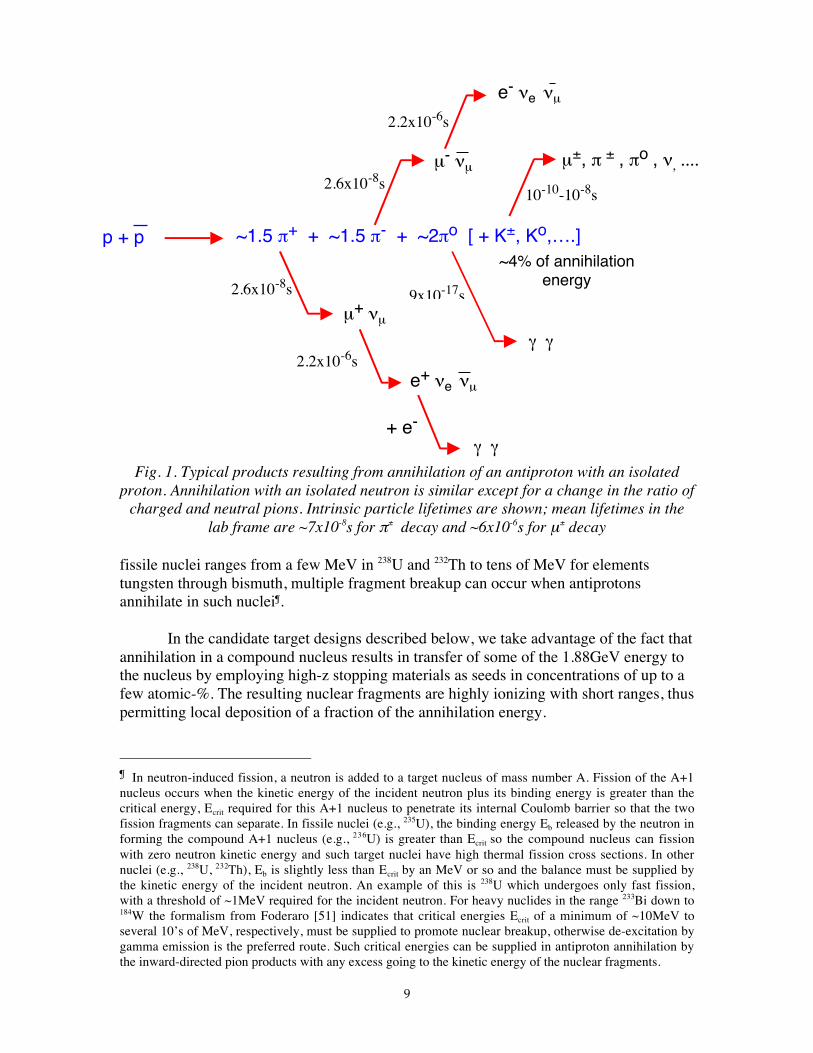
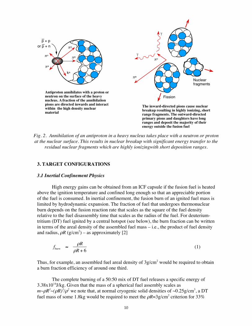
The annihilation of antiprotons is a strong interaction process that takes place atthe level of the quark structure of the nucleus. Antiproton annihilation with an isolatedproton at rest is shown in Fig. 1, where we indicate typical average number of daughterparticles produced. The division of the 1.88GeV annihilation energy is, initially, ~64% tothe kinetic energy of the pions and ~36% to their rest energy. In ~5% of annihilationevents, a kaon pair is also emitted. These meson products are all unstable, thus severaldecay chains subsequently occur as shown in the figure. The neutral pion (πo) with itsvery short lifetime, travels less than a micron before decaying into two energetic gammarays. Most of this gamma energy will escape the capsule. The charged pions (π±) decayinto muons (µ±) and neutrinos (νe,m). The muons then further decay into electrons (e-)and positrons (e+), and the latter subsequently annihilate with electrons in thesurrounding medium.
Due to the different quark structures of protons and neutrons*, the reactionproducts from antiproton annihilation with an isolated neutron are slightly different fromthose shown above with an isolated proton. In the case of neutrons, the mean number ofnegative pions is one greater than the mean number of positive pions and the ratio ofcharged to neutral pions is somewhat greater [49].
The above particle and energy distributions apply to annihilation of an antiprotonwith a single, isolated proton (i.e., hydrogen nucleus) or neutron. Annihilation with anormal matter nucleon within a heavy nucleus of A>>1 produces rather differentproducts and energetics. A fraction of available annihilation energy is transferred to theheavy nucleus via pion interactions as shown in Fig. 2. The nucleus can break up in a“super fission” process resulting in highly ionizing, short-range nuclear fragments. Insuch case, the total energy released can be more than the 1.88GeV from annihilation dueto the fission contribution – i.e., the repulsive Coulomb energy. Experimental resultsfrom Smith [23], Angelopoulos et al. [24] and Machner et al. [25] claim that annihilationwith uranium induces conventional binary fission in ~100% of the events, while Schmidet al [30] obtains only 77% binary fissions with the balance to multiple lighter 238Ufragments. Note also that because the critical energy to promote fission in heavy, non-
* The proton is composed of two "up" quarks, each of charge +2/3, plus one "down" quark of charge -1/3.The neutron is composed of two down quarks plus one up quark, while the antiproton has two anti-upquarks (charge -2/3) plus one anti-down quark (charge +1/3). The mesons resulting from the annihilationreactions are composed of quark-antiquark pairs; e.g. the positive pion is composed of an up quark (charge+2/3) and an anti-down quark (charge +1/3).
9
Fig. 1. Typical products resulting from annihilation of an antiproton with an isolatedproton. Annihilation with an isolated neutron is similar except for a change in the ratio of
charged and neutral pions. Intrinsic particle lifetimes are shown; mean lifetimes in thelab frame are ~7x10⁻⁸s for π± decay and ~6x10⁻⁶s for µ± decay
fissile nuclei ranges from a few MeV in 238U and 232Th to tens of MeV for elementstungsten through bismuth, multiple fragment breakup can occur when antiprotonsannihilate in such nuclei¶.
In the candidate target designs described below, we take advantage of the fact thatannihilation in a compound nucleus results in transfer of some of the 1.88GeV energy tothe nucleus by employing high-z stopping materials as seeds in concentrations of up to afew atomic-%. The resulting nuclear fragments are highly ionizing with short ranges, thuspermitting local deposition of a fraction of the annihilation energy.
¶ In neutron-induced fission, a neutron is added to a target nucleus of mass number A. Fission of the A+1nucleus occurs when the kinetic energy of the incident neutron plus its binding energy is greater than thecritical energy, Ecrit required for this A+1 nucleus to penetrate its internal Coulomb barrier so that the twofission fragments can separate. In fissile nuclei (e.g., 235U), the binding energy Eb released by the neutron informing the compound A+1 nucleus (e.g., 236U) is greater than Ecrit so the compound nucleus can fissionwith zero neutron kinetic energy and such target nuclei have high thermal fission cross sections. In othernuclei (e.g., 238U, 232Th), Eb is slightly less than Ecrit by an MeV or so and the balance must be supplied bythe kinetic energy of the incident neutron. An example of this is 238U which undergoes only fast fission,with a threshold of ~1MeV required for the incident neutron. For heavy nuclides in the range 233Bi down to184W the formalism from Foderaro [51] indicates that critical energies Ecrit of a minimum of ~10MeV toseveral 10’s of MeV, respectively, must be supplied to promote nuclear breakup, otherwise de-excitation bygamma emission is the preferred route. Such critical energies can be supplied in antiproton annihilation bythe inward-directed pion products with any excess going to the kinetic energy of the nuclear fragments.
p + p~4% of annihilation
energy2.6x10-8s
µ+ νµ
e+ νe νµ
2.2x10⁻⁶s
+ e-
γ γ
2.6x10⁻⁸sµ- νµ
e- νe νµ
2.2x10⁻⁶s
γ γ
9x10-17s
10-10-10-8s
µ±, π ± , πo , ν, ....
~1.5 π+ + ~1.5 π- + ~2πo [ + K±, Ko,….]
10
πο
π±
π±
k±
π±
Antiproton annihilates with a proton or neutron on the surface of the heavy nucleus. A fraction of the annihilation pions are directed inwards and interact within the high density nuclear material
The inward-directed pions cause nuclear breakup resulting in highly ionizing, short range fragments. The outward-directed primary pions and daughters have long ranges and deposit the majority of their energy outside the fusion fuel
π±
πο
γ
γ
Fission
Nuclear fragments
p + por p + n
Fig. 2. Annihilation of an antiproton in a heavy nucleus takes place with a neutron or protonat the nuclear surface. This results in nuclear breakup with significant energy transfer to the
residual nuclear fragments which are highly ionizingwith short deposition ranges.
3. TARGET CONFIGURATIONS
3.1 Inertial Confinement Physics
High energy gains can be obtained from an ICF capsule if the fusion fuel is heatedabove the ignition temperature and confined long enough so that an appreciable portionof the fuel is consumed. In inertial confinement, the fusion burn of an ignited fuel mass islimited by hydrodynamic expansion. The fraction of fuel that undergoes thermonuclearburn depends on the fusion reaction rate that scales as the square of the fuel densityrelative to the fuel disassembly time that scales as the radius of the fuel. For deuterium-tritium (DT) fuel ignited by a central hotspot (see below), the burn fraction can be writtenin terms of the areal density of the assembled fuel mass – i.e., the product of fuel densityand radius, ρR (g/cm2) – as approximately [2]
fR
Rburn ≈+
ρρ 6
(1)
Thus, for example, an assembled fuel areal density of 3g/cm2 would be required to obtaina burn fraction efficiency of around one third.
The complete burning of a 50:50 mix of DT fuel releases a specific energy of3.38x1014J/kg. Given that the mass of a spherical fuel assembly scales asm~ρR3~(ρR)3/ρ2 we note that, at normal cryogenic solid densities of ~0.25g/cm3, a DTfuel mass of some 1.8kg would be required to meet the ρR=3g/cm2 criterion for 33%
11
burnup. This would result in a fusion yield of ~2x10¹⁴J; that is, some 50kilotons of high-explosive-equivalent energy release. However, initial compression of the fuel to densitiesof, say, 200g/cm3 at the same ρR=3g/cm2 condition would reduce this unmanageableyield to ~300MJ in a fuel mass of only ~3mg, thus making it suitable for terrestrial powerproduction or space propulsion at a repetition rate of several hertz.
A typical ICF fusion target consists of several milligrams of cryogenic solid DTfuel in the form of a spherical shell surrounding a region of low density (~mg/cm3) DTgas. The fuel is surrounded by an outer ablator region of mass comparable to that of thefuel and of a material selected to optimize the implosion dynamics. In conventional ICF,energy is rapidly coupled to the ablator from a driver – either directly in the form ofsymmetrical laser beams or indirectly in the form of x-rays stimulated by lasers, heavy-ion beams or z-pinches in a surrounding hohlraum [1-6,12,52]. As the heated ablatorexpands outwards, momentum conservation causes the remaining target to be implodedinward by the rocket effect. With a suitable temporal profile on the drive intensity, thefuel can be maintained relatively cold near the minimum Fermi temperature as it iscompressed by the resulting shock waves. At peak drive pressure, the capsule approachesa state of uniform acceleration [11] until spherical convergence effects and gasbackpressure cause the fuel to stagnate at high density. As described below, the peakvelocity achieved during the implosion is a crucial parameter in determining both thepeak compression density and the minimum energy required to cause the fuel to ignite.
Below, we define three major classes of ICF targets, first from a conventionalperspective and then describe how they might be adapted for use with antiproton drive.They are differentiated by (a) the target design, (b) how the implosion is performed and(c) whether a separate ignition source is employed .
3.2 Antiproton Volumetric Ignition
In volumetric ignition, the bulk of the compressed fuel mass is raised to theignition temperature, typically Tignt3keV for DT. These types of conditions can begenerated in conventional ICF targets if, for example, electrons generated by a high-intensity laser interact in a thin (~few µm) metal or glass shell enclosing a cryogenicsolid or liquid DT core. The shell heats rapidly to keV temperatures, exploding the shellwith a pressure of many gigabars and driving an inward shock at a velocity of a ~few×107cm/s. The convergent shock from the shell heats the DT core yielding iontemperatures in the ~3-10keV range. Such “exploding pusher” targets were the mostcommon types of targets utilized in the early stages of the ICF program and were the firsttype to produce thermonuclear neutrons. They can more easily achieve higher implosionvelocities than the conventional hot-spot targets described below and, due to their lowconvergences, are more tolerant of asymmetries in the drive. However, they typically donot scale to high gain because the bulk of the DT fuel is preheated. This sets the targetmass on a high isentrope which precludes high compression densities with moderateincident energies.
In principle, antiprotons can be arranged to annihilate in the bulk of a compressedDT fuel mass to drive volumetric ignition. However, because of the long range of theannihilation pions produced in the low-z fuel (Fig. 1) the energy deposition efficiencywould be low. To ameliorate this problem, seeding the fuel with a small atomic fraction of
12
heavy metal can augment energy deposition in the fuel as described above (Fig. 2) but atthe expense of high-z impurity mix and attendant increases in radiation losses. Severalauthors have suggested using antiproton-induced fission to boost the burning of fusionfuel [33-38] and Smith et al proposed the ICAN concept for application to propulsion [34].
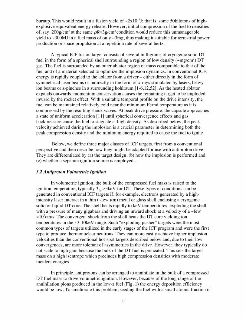
Fig. 3. Antiproton-driven volumetric ignition. Antiprotons are injected into theprecompressed fuel which is seeded with heavy metal to enhance energy deposition of
annihilation products.
A schematic is shown in Fig 3. Antiprotons annihilate in a DT fuel mass seededwith a heavy metal, say uranium, at the ~0.5-10 atomic-% level. The fuel plus seed isprecompressed by either by a conventional driver – Smith [34] advocated high intensity,lithium light ion beams – or prior p ablative drive in an outer ablator as described below.Antiprotons preferentially annihilate with the heavy metal seed resulting in energydeposition in the fuel by short range nuclear fragments. The total nuclear yield in thetarget is the sum of the deposited antiproton induced energy plus the yields from DTfusion and, where applicable, conventional uranium fission induced by fusion neutrons.
3.3 Antiproton Hotspot Ignition
The minimum energy required to volumetrically heat a DT fuel mass to ignitiontemperature T = Ti ~ Te is 1.15x10¹¹T(keV) J/kg, whereas the specific energy to compressit to Fermi-degenerate density ρ is only ~3 x10⁸ρ2/3J/kg, with ρ in units of g/cm3 [2]. So ifthe target can be isentropically compressed on a low adiabat – that is, kept relatively coldwith minimum temperatures set by the Fermi energy – but ignited from a central hightemperature core, gains can be significantly higher and driver sizes reduced accordingly.In such “hotspot” ignition targets, the final assembled state consists of a central, lowdensity, high temperature region containing only a few percent of the fuel mass inapproximate pressure equilibrium with the bulk of the surrounding cold compressed fuel
p-p or p -nannihilation in D or T
π±
π±
Pre-compressed DT fuel(conventional driver)
U seeding(few atomic-%)
p annihilation with U⇒ short range super fissionfragments
Long rangeannihilation pions
p injection kinetic energyadjusted to stop in fuel
13
at high density. The conditions for ignition, i.e., burn propagation from the hotspot intothe cold fuel, is approximately a hotspot temperature of Tignt10keV over a region of localareal density of (ρR)ign~0.3g/cm2. The overall fuel burnup and fusion yield is thendetermined by the total ρR of the assembled fuel as described above (see Eqn. (1))
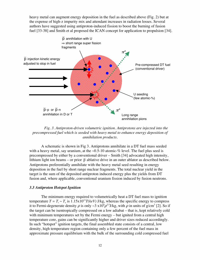
In principle, antiprotons could be used to drive a hotspot ignition target replacingthe conventional direct or indirect driver system, i.e., laser, heavy-ion beam or z-pinch –see Fig 4 where a section of the spherical target is shown. Target dimensions will bediscussed in Section 5 below. The kinetic energy of the antiproton beam is controlled sothat they annihilate at the ablation front. In the target designs of this paper, the kineticenergy required of the injected antiprotons is typically less than one percent of their netdeposited annihilation energy. As with volumetric ignition above, a heavy metal seed willbe required to enhance antiproton energy deposition. Here, however, the seed is placedonly in the ablator and not in the fuel itself.
In the hotspot ignition example analyzed below, we will focus on a direct-driveconcept where the antiprotons annihilate directly with the ablator shell although theprinciples could be applied to indirect-drive via antiproton-induced x-ray productionwithin a high-z hohlraum case. A “semi-indirect-drive” antiproton-driven configurationmay also be possible, where the ablator is surrounded by a thin outer high-z shell stoodoff from the ablator by a foam buffer layer. The kinetic energy of the antiprotons wouldbe adjusted to penetrate the shell and interact in the ablator with the resulting radiationcontained by the shell acting as a close-coupled spherical hohlraum.
Relative to p-driven volumetric ignition, we would expect to realize thefollowing advantages with p-driven hotspot ignition:
DT gas (~6x10⁻⁴ g/cm3)
DT fuel (5mg)1 .78mm
2.50mm
DT ablator+ U seeding2.18mm
Antiproton injection.– kinetic energy adjustedto ~1.4MeV to annihilateat center of ablation front(≈ fission fragment range)
Fig. 4. Section of thespherical target forantiproton-driven hotspotignition. A direct driveconfiguration is shown herebut semi-indirect driveoptions are also possible.Target specifications arediscussed in Section 5.
14
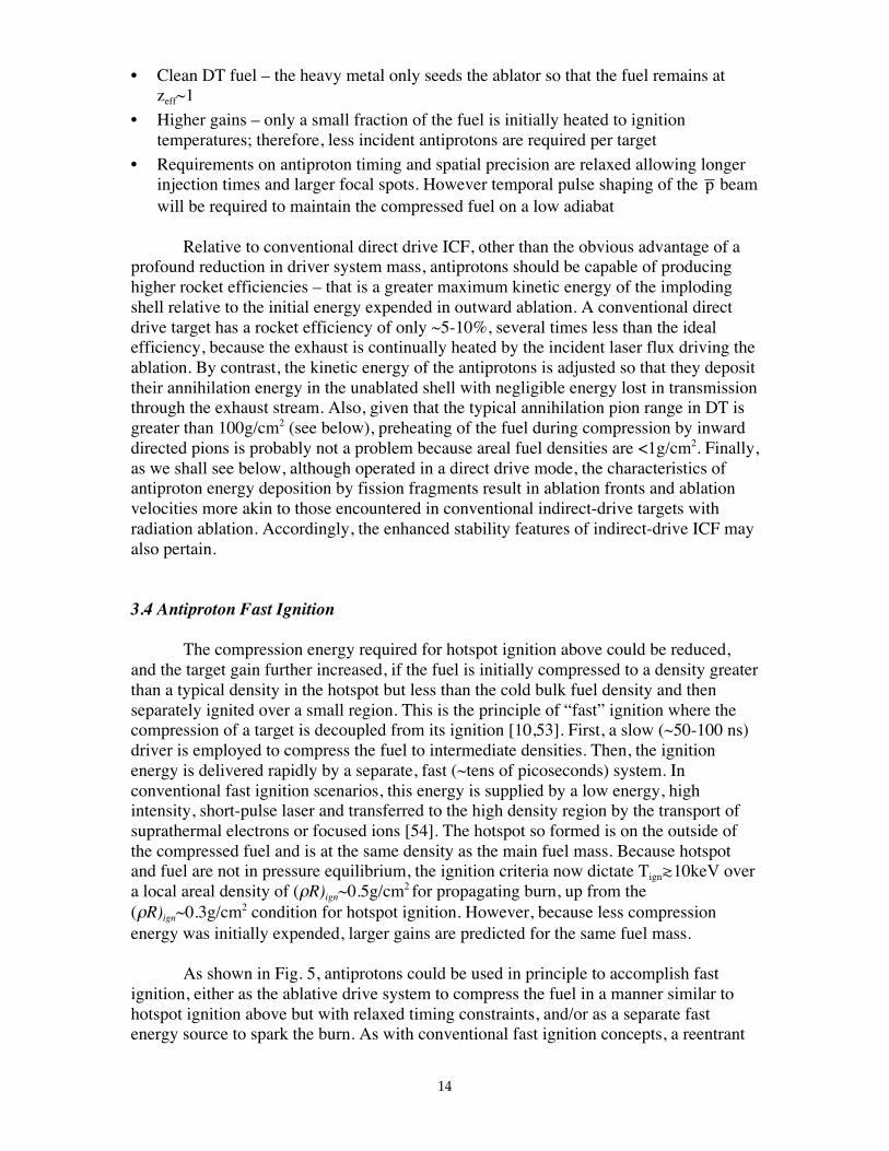
• Clean DT fuel – the heavy metal only seeds the ablator so that the fuel remains atzeff~1
• Higher gains – only a small fraction of the fuel is initially heated to ignitiontemperatures; therefore, less incident antiprotons are required per target
• Requirements on antiproton timing and spatial precision are relaxed allowing longerinjection times and larger focal spots. However temporal pulse shaping of the p beamwill be required to maintain the compressed fuel on a low adiabat
Relative to conventional direct drive ICF, other than the obvious advantage of aprofound reduction in driver system mass, antiprotons should be capable of producinghigher rocket efficiencies – that is a greater maximum kinetic energy of the implodingshell relative to the initial energy expended in outward ablation. A conventional directdrive target has a rocket efficiency of only ~5-10%, several times less than the idealefficiency, because the exhaust is continually heated by the incident laser flux driving theablation. By contrast, the kinetic energy of the antiprotons is adjusted so that they deposittheir annihilation energy in the unablated shell with negligible energy lost in transmissionthrough the exhaust stream. Also, given that the typical annihilation pion range in DT isgreater than 100g/cm2 (see below), preheating of the fuel during compression by inwarddirected pions is probably not a problem because areal fuel densities are <1g/cm2. Finally,as we shall see below, although operated in a direct drive mode, the characteristics ofantiproton energy deposition by fission fragments result in ablation fronts and ablationvelocities more akin to those encountered in conventional indirect-drive targets withradiation ablation. Accordingly, the enhanced stability features of indirect-drive ICF mayalso pertain.
3.4 Antiproton Fast Ignition
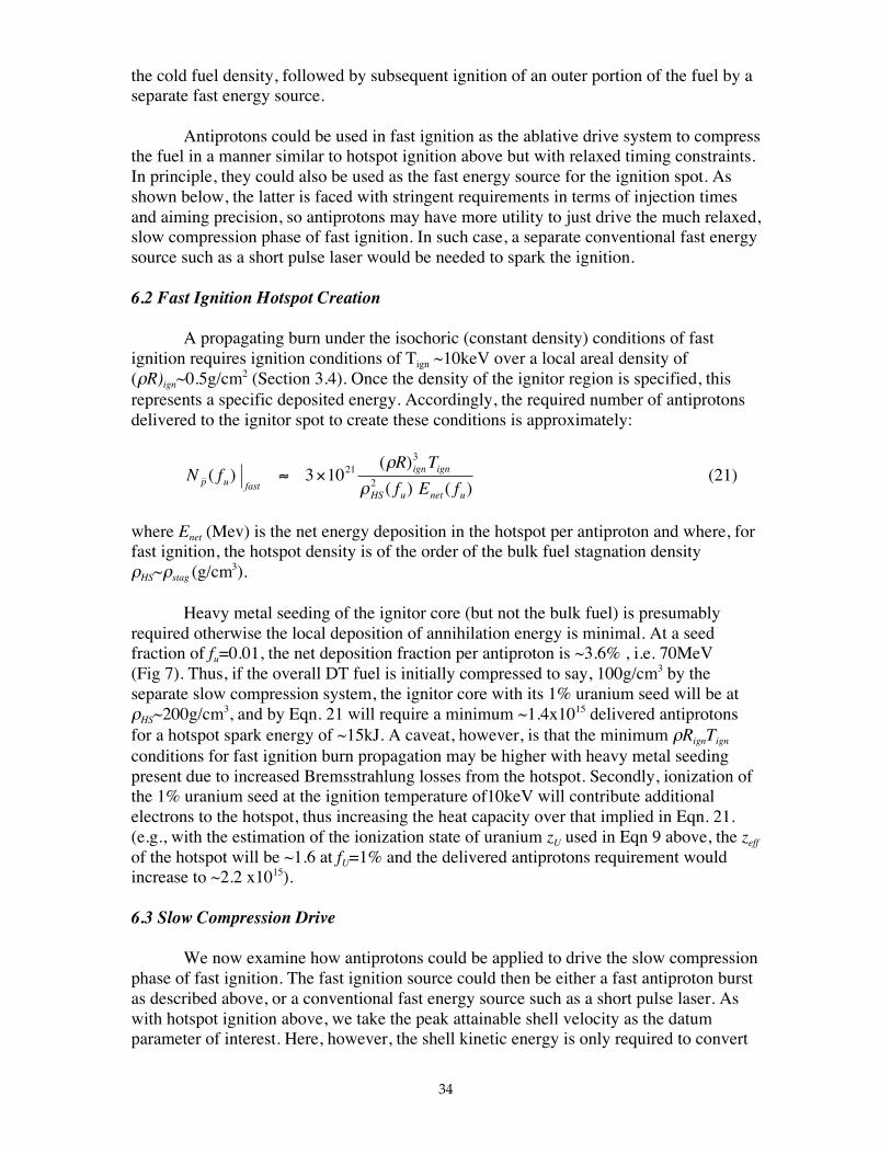
The compression energy required for hotspot ignition above could be reduced,and the target gain further increased, if the fuel is initially compressed to a density greaterthan a typical density in the hotspot but less than the cold bulk fuel density and thenseparately ignited over a small region. This is the principle of “fast” ignition where thecompression of a target is decoupled from its ignition [10,53]. First, a slow (~50-100 ns)driver is employed to compress the fuel to intermediate densities. Then, the ignitionenergy is delivered rapidly by a separate, fast (~tens of picoseconds) system. Inconventional fast ignition scenarios, this energy is supplied by a low energy, highintensity, short-pulse laser and transferred to the high density region by the transport ofsuprathermal electrons or focused ions [54]. The hotspot so formed is on the outside ofthe compressed fuel and is at the same density as the main fuel mass. Because hotspotand fuel are not in pressure equilibrium, the ignition criteria now dictate Tignt10keV overa local areal density of (ρR)ign~0.5g/cm2 for propagating burn, up from the(ρR)ign~0.3g/cm2 condition for hotspot ignition. However, because less compressionenergy was initially expended, larger gains are predicted for the same fuel mass.
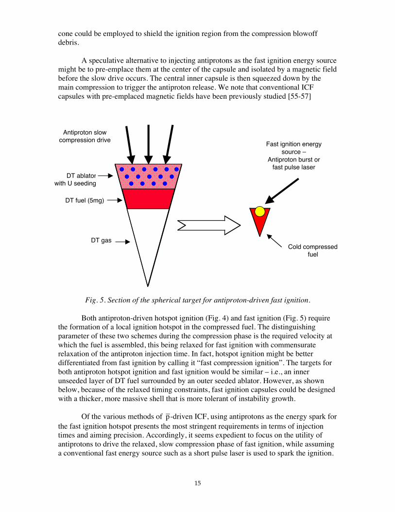
As shown in Fig. 5, antiprotons could be used in principle to accomplish fastignition, either as the ablative drive system to compress the fuel in a manner similar tohotspot ignition above but with relaxed timing constraints, and/or as a separate fastenergy source to spark the burn. As with conventional fast ignition concepts, a reentrant
15
cone could be employed to shield the ignition region from the compression blowoffdebris.
A speculative alternative to injecting antiprotons as the fast ignition energy sourcemight be to pre-emplace them at the center of the capsule and isolated by a magnetic fieldbefore the slow drive occurs. The central inner capsule is then squeezed down by themain compression to trigger the antiproton release. We note that conventional ICFcapsules with pre-emplaced magnetic fields have been previously studied [55-57]
Fig. 5. Section of the spherical target for antiproton-driven fast ignition.
Both antiproton-driven hotspot ignition (Fig. 4) and fast ignition (Fig. 5) requirethe formation of a local ignition hotspot in the compressed fuel. The distinguishingparameter of these two schemes during the compression phase is the required velocity atwhich the fuel is assembled, this being relaxed for fast ignition with commensuraterelaxation of the antiproton injection time. In fact, hotspot ignition might be betterdifferentiated from fast ignition by calling it “fast compression ignition”. The targets forboth antiproton hotspot ignition and fast ignition would be similar – i.e., an innerunseeded layer of DT fuel surrounded by an outer seeded ablator. However, as shownbelow, because of the relaxed timing constraints, fast ignition capsules could be designedwith a thicker, more massive shell that is more tolerant of instability growth.
Of the various methods of p-driven ICF, using antiprotons as the energy spark forthe fast ignition hotspot presents the most stringent requirements in terms of injectiontimes and aiming precision. Accordingly, it seems expedient to focus on the utility ofantiprotons to drive the relaxed, slow compression phase of fast ignition, while assuminga conventional fast energy source such as a short pulse laser is used to spark the ignition.
DT gas
DT fuel (5mg)
Antiproton slowcompression drive
Fast ignition energysource –
Antiproton burst orfast pulse laser
Cold compressedfuel
DT ablatorwith U seeding
16
3.5 Muon Catalysis
We note from Fig. 1 that negative muons are produced in the decay of theannihilation pions. Deposition of these muons in DT fuel could, in principle, promotefusion by muon catalysis. Here, a thermalized heavy negative muon binds tightly to a fuelnucleus and reduces the width of the conventional repulsive Coulomb barrier between itand a neighboring fuel nucleus by a factor of mµ/me~200, thus permitting fusion toproceed at significantly below eV temperatures [58]. Typically, a maximum of ~150 DTfusions can be catalyzed per muon because the latter is ultimately lost by sticking to anoutgoing alpha particle. This could result in an additional energy deposition of up to~500MeV per original p via 3.5MeV fusion alpha particles. However, only a smallfraction of the muons produced by pion decay will be captured locally. Also, the lifetimefor π- decay to muons is ~70ns in the lab frame which is too slow for muon catalysis tocontribute usefully to energy deposition in any of the above target designs other than,perhaps, the slow compression phase of fast ignition. Furthermore, ultimate muon decay(~6µs in the lab frame) is too fast to permit muon collection and re-injection into asubsequent capsule unless the latter is a separate component of the same target assembly.Accordingly, we will not consider muon catalysis further in the antiproton energydeposition process.
The target for this concept was introduced in Section 3.2 above and shownin Fig. 3. We will here consider antiprotons to annihilate in a precompressed DT fuelmass seeded with a heavy metal. In this example we will use uranium in the form of 238Uas the seed – this closely approximates natural uranium at 99.3% 238U – although otherheavy metals such as tungsten through bismuth could be employed. The advantage ofuranium is that it can also undergo conventional fast fission so that additional target yieldcan result from subsequent fusion-neutron-induced fission in the seed material. Weassume that fuel precompression is performed by a conventional driver; in the nextsection we will examine fuel compression by antiproton-driven ablation. Antiprotonspreferentially interact with the metal seed resulting in energy deposition in the fuelmainly by short range nuclear fragments rather than the long range pions that wouldresult from annihilation in pure DT. The total energy produced in the target is the sum ofthe DT fusion yield and subsequent fusion-neutron-induced uranium fission yield.
We proceed with the analysis as follows, employing 1-D simulations with theLASNEX radiation-hydrodynamics-burn code [59]. We start a given DT fuel mass at t=0at full compressed density and a given uranium seed fraction. We investigate the fuelignition/burn conditions and overall yield as a function of the initial temperature of thecompressed fuel. We then compute the requirements for antiproton slowing down,capture and energy deposition that would produce a volumetric ignition energy sourceconsistent with these initial conditions and thereby deduce the required number ofinjected antiprotons together with the necessary initial compression energy. There arethus four independent variables for this analysis: DT fuel mass, 238U seed fraction, initialdensity (i.e., initial ρ-R) and initial temperature.
17
We assume the initial kinetic energy of the antiproton beam is adjusted toannihilate within the bulk of the seeded DT fuel. As the nuclear fragment range is muchless than the compressed fuel radius, we take the fragment energy to be deposited whereborn. (In Section 5 below on hotspot ignition targets with antiproton-driven ablation, wewill need to accommodate fission fragment ranges explicitly). By contrast, theannihilation pion range is typically greater than the fuel dimensions and we compute itsfractional energy deposition consistently. To avoid computing time-dependent slowingdown, we assume that the ignition energy is deposited in a time less than thehydrodynamic disassembly time of the compressed fuel, thus setting a maximum pulselength on the injected antiprotons; this parameter increases (i.e., becomes less stringent)as the seed fraction and target mass increase.
We might expect that we need sufficient uranium seed fraction to preferentiallycapture the antiprotons and promote enhanced local energy deposition but not too highotherwise unacceptable “mix” will result with high zeff and deleterious Bremsstrahlunglosses. Therefore, we might expect there is an optimum seed fraction that will maximizethe target gain – that is, maximize the ratio of nuclear yield to the number of injectedantiprotons required to establish the initial ignition conditions. In fact, as we shall see, anincreasing U seed fraction results in a greater fraction of the yield coming fromconventional fast neutron fission in 238U relative to DT fusion and there is no clearoptimum in the burn energetics.
4.2 Burn Calculations
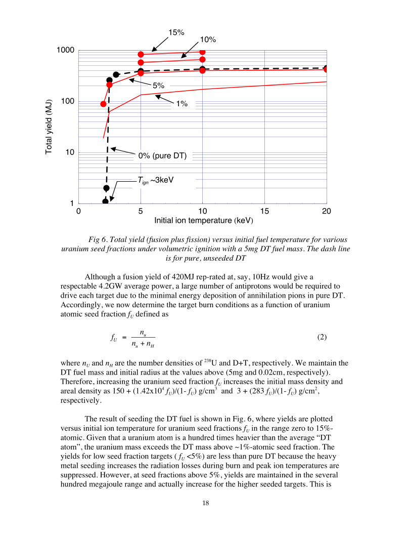
We select an initial DT mass of 5mg for these example calculations, typical of afuel mass used in conventional high yield ICF reactor applications [3-6], and assume thatit is precompressed by a conventional driver to an areal density of ρR = 3g/cm2, that is, anaverage density of ρ ~150g/cm3 (for unseeded pure DT) and spherical radius of ~0.02cm.The compression energy will be considered further below. If this compressed mass wasignited by a central hotspot we would expect, by Eqn. 1, a fuel burnup of around one-third and a fusion yield of ~560MJ. As we shall see, volumetric ignition results in a lowerachievable yield. Employing LASNEX in 1-D spherical geometry, we determine theminimum volumetric ion temperature at which the fuel ignites – that is, produces asignificant multiplicity in ion temperature together with a substantial fusion yield. Theantiproton deposition characteristics necessary to achieve these initial conditions will beconsidered below. The dashed line in Fig. 6 shows the yield for pure unseeded DT as afunction of the initial volumetric ion temperature To. The required initial temperature forignition is seen to be around Tign = To ~2.5-3keV where a yield of ~300MJ is achieved.The yield increases with increasing To above 3keV and saturates at ~420MJ around To
~10-20keV. Once the initial temperature is at or above the ignition temperature, peak iontemperatures climb during the burn to ~100keV. We note these yields are typically lessthan those achievable with central hotspot ignition under the same ρ-R conditionsbecause the fuel is volumetrically preheated and outward expansion quenches the burnmore rapidly.
18
Fig 6. Total yield (fusion plus fission) versus initial fuel temperature for variousuranium seed fractions under volumetric ignition with a 5mg DT fuel mass. The dash line
is for pure, unseeded DT
Although a fusion yield of 420MJ rep-rated at, say, 10Hz would give arespectable 4.2GW average power, a large number of antiprotons would be required todrive each target due to the minimal energy deposition of annihilation pions in pure DT.Accordingly, we now determine the target burn conditions as a function of uraniumatomic seed fraction fU defined as
fn
n nUu
u H
=+
(2)
where nU and nH are the number densities of 238U and D+T, respectively. We maintain theDT fuel mass and initial radius at the values above (5mg and 0.02cm, respectively).Therefore, increasing the uranium seed fraction fU increases the initial mass density andareal density as 150 + (1.42x10⁴ fU)/(1- fU) g/cm3 and 3 + (283 fU)/(1- fU) g/cm2,respectively.
The result of seeding the DT fuel is shown in Fig. 6, where yields are plottedversus initial ion temperature for uranium seed fractions fU in the range zero to 15%-atomic. Given that a uranium atom is a hundred times heavier than the average “DTatom”, the uranium mass exceeds the DT mass above ~1%-atomic seed fraction. Theyields for low seed fraction targets ( fU <5%) are less than pure DT because the heavymetal seeding increases the radiation losses during burn and peak ion temperatures aresuppressed. However, at seed fractions above 5%, yields are maintained in the severalhundred megajoule range and actually increase for the higher seeded targets. This is
0 5 10 15 20Initial ion temperature HkeVL
1
10
100
1000T
otal
yiel
dHM
JL
Tign ~3keV
15%10%
1%
5%
0% (pure DT)
19
because primary and down scattered 14MeV neutrons from the DT fusion reaction canpromote fast fission in the uranium seed nuclei within the compressed fuel (the neutronthreshold energy is ~1MeV). Our LASNEX calculations evaluate the neutron transportand fission rates consistently with the fusion burn so that as fU increases, an increasingfraction of the total yield shown in Fig. 6 is due to conventional 238U fast fission. Thepartitioning of the fission and fusion yields will be discussed below, where we show thatthe fission yield becomes the dominant contributor to the total yield above a seed fractionof about 13%. The seeded targets have considerably lower peak burn temperaturesrelative to pure DT but comparable yields. For example, pure DT with fU=0 demonstrateda maximum yield of ~420MJ with peak ion temperatures of ~100keV. By contrast, atarget with fU=5% exhibits a peak burn temperature of only ~25keV but comparable peakyields of ~400MJ. Thus the increasing zeff and radiation losses with increasing seedfraction that suppress peak burn temperatures are offset by the increasing fission yieldand by the tamping effect of the larger target mass. For example, the disassembly time fora 1/e reduction in the initial density is a factor of three longer for the fU=5% target relativeto the pure DT target.
4.3 Antiproton Energy Deposition.
Given the burn dynamics above, we now estimate the antiproton injectionrequirements to initiate the target conditions at t=0. As shown in Fig 2, annihilation witha heavy nucleus takes place with a proton or neutron near the surface. The outwarddirected pions or kaons have long ranges even in the pre-compressed fuel (see below) soonly a small fraction of their ionization energy will be deposited . Similarly, the neutralpion decays in ~10-18s into two energetic gamma rays which also leave the target withminimal local energy deposition. By contrast, the mesons directed into the heavy nucleusencounter a medium of nuclear density. Their interaction mean free path is thenapproximately
λ σπσ
= [ ] ≈−nr
AN1
43
3
(3)
where n is the nucleon number density, σ is the pion-nucleon interaction cross section, Ais the nuclear mass number and rN is the nuclear radius. Taking σ~100mb for ~100MeVpions [60] and rN=1.2A1/3×10-15m, gives a nuclear density of n~1.4×1044m-3 for A=238and, thus, a pion mean free path of only ~7×10-16m. This is about a tenth of the nuclearradius thus ensuring that all the inward directed pion energy is transferred to the nucleusand its subsequent breakup. The resulting nuclear products are highly ionizing with shortranges.
An antiproton slowing down in the seeded fuel will be captured by either a U orD/T nucleus when its local velocity has reduced to the order of that of an outer (bound)orbital electron in that nucleus. For DT (i.e., hydrogen), the radius of the first electronBohr orbit is ~5.3x10⁻¹¹m and its orbital velocity is v0=αc= 2.2 x10⁶m/s, where α is thefine structure constant. The equivalent kinetic energy of an antiproton with this velocityis ~25keV. Assuming that the incident kinetic energy of the antiproton is adjusted so thatit always stops in the bulk fuel by annihilation with either 238U or DT, the total fraction of
20
the available 1.88GeV annihilation energy deposited in the fuel therefore depends on theprobability of antiproton capture by uranium to the probability of capture by a DTnucleus. Using the conventional method of combining macroscopic cross sections, Σ, wewrite the probability of capture by uranium as
p pn
n nU HU
U H
U U
U U H H
= − ≈+
=+
1Σ
Σ Σσ
σ σ(4)
where nU and nH are the number densities of uranium and D+T, respectively, and σU andσH are the microscopic capture cross sections and pH is the probability of capture by DT.Using a semi classical argument, Morgan and Hughes [61] show that the p H− collisioncapture cross section can be written
σ πH ok c v r= ( / ) 2 (5)
where v is the relative p H−
− velocity, ro is the classical outer electron radius andk=3.60x10⁵ is a dimensionless constant. Taking ro for DT as the first Bohr orbit and, byanalogy, an outer electron radius for 238U as ~1.38x10⁻¹⁰m [62] we can use Eqn. 4 toestimate the probability of capture by the heavy metal as a function of uranium seedfraction fU defined in Eqn. 2 above. The energy deposited in the fuel per antiprotoninjected can now be determined as a function of the uranium seed fraction fu as
E f p f p E p fR f
REnet u u u f f u u
u( ) ( ) ( ( ) )( )
( )≈ < > + − < >1
ρρ π
π (6)
where the first and second terms represent the energy deposition contributions from shortrange uranium breakup and long range DT-produced pions, respectively , and where pu isthe probability of capture by uranium, 1-pH is the probability of capture by DT, pf is theprobability that an annihilation event with an outer 238U nucleon will result in fission ofthe nucleus, <Ef> is the average energy of the super fission fragments, ρR is the arealdensity of the compressed fuel, and (ρR)π is the areal range of the charged annihilationpions of average energy <E π>.
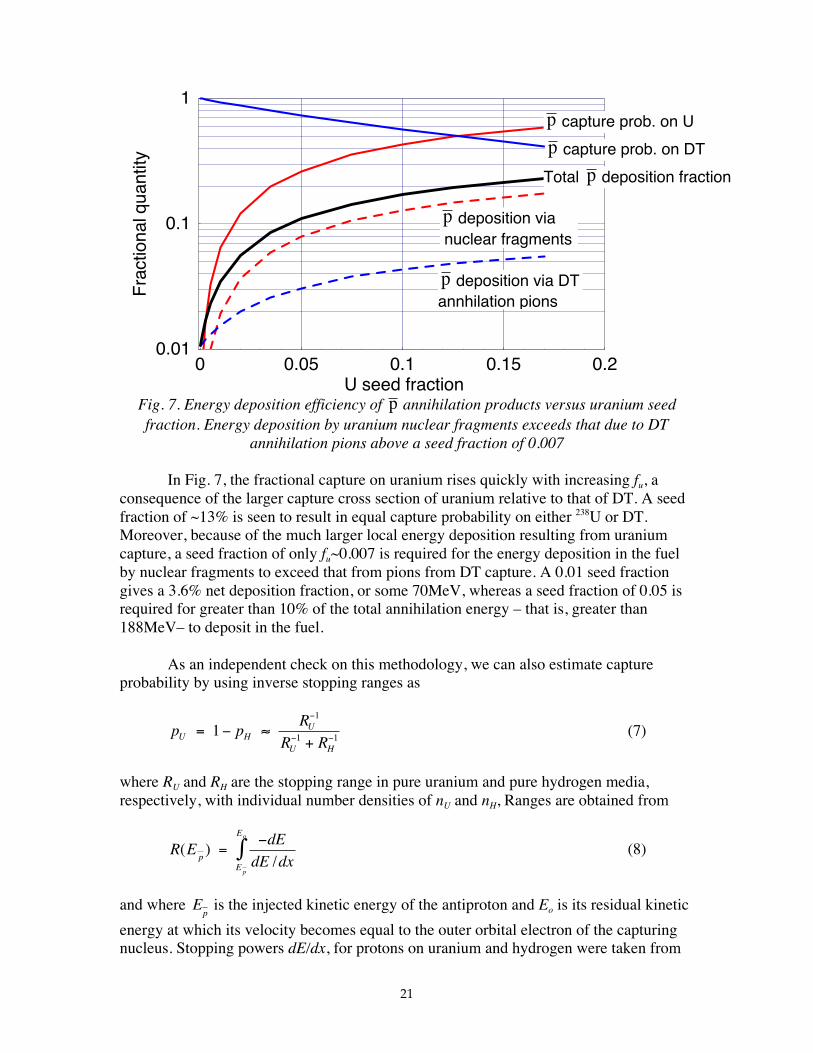
The effects of applying Eqns. 4 and 6 are shown in Fig 7 where the captureprobabilities on uranium and DT are shown as a function of seed fraction fu, together withthe resulting net energy depositions expressed as a fraction of the gross 1.88GeVannihilation energy. Theses results use (a) a p-induced fission probability for uranium of0.8 which is the average of experimental results from Schmid [30], (b) a total superfission fragment energy release (including the incident pion energies and Coulombrepulsion energy) of ~700MeV from VonEdigy [29], and (c) a total charged pion kineticenergy of 713.5MeV distributed, on average, over 1.5 π+ and 1.5 π− [49]. We estimate thepion range (ρR)π in a mixture of U and DT by noting that it can be written in terms of aproton range in the same material at the same velocity multiplied by the ratio of the pionmass to the proton mass; the method for the proton range calculation is discussed below.
21
Fig. 7. Energy deposition efficiency of p annihilation products versus uranium seedfraction. Energy deposition by uranium nuclear fragments exceeds that due to DT
annihilation pions above a seed fraction of 0.007
In Fig. 7, the fractional capture on uranium rises quickly with increasing fu, aconsequence of the larger capture cross section of uranium relative to that of DT. A seedfraction of ~13% is seen to result in equal capture probability on either 238U or DT.Moreover, because of the much larger local energy deposition resulting from uraniumcapture, a seed fraction of only fu~0.007 is required for the energy deposition in the fuelby nuclear fragments to exceed that from pions from DT capture. A 0.01 seed fractiongives a 3.6% net deposition fraction, or some 70MeV, whereas a seed fraction of 0.05 isrequired for greater than 10% of the total annihilation energy – that is, greater than188MeV– to deposit in the fuel.
As an independent check on this methodology, we can also estimate captureprobability by using inverse stopping ranges as
p pR
R RU HU
U H
= − ≈+
−
− −11
1 1 (7)
where RU and RH are the stopping range in pure uranium and pure hydrogen media,respectively, with individual number densities of nU and nH, Ranges are obtained from
R EdE
dE dxpE
E
p
o
( )/
=−∫ (8)
and where Ep is the injected kinetic energy of the antiproton and Eo is its residual kinetic
energy at which its velocity becomes equal to the outer orbital electron of the capturingnucleus. Stopping powers dE/dx, for protons on uranium and hydrogen were taken from
0 0.05 0.1 0.15 0.2U seed fraction
0.01
0.1
1
Fra
ctio
nalq
uant
ityp capture prob. on U
p capture prob. on DT
Total p deposition fraction
p deposition vianuclear fragments
p deposition via DTannhilation pions
22
Anderson and Zeigler [63] which are accurate for 1keV≤ Ep≤100MeV. The required
injection kinetic energies for antiproton penetration through the compressed, seeded DTare discussed below but we note that because a ratio of ranges is used in Eqn. 7, theprecise upper limit is not crucial to evaluate Eqn 8. The result of using Eqn.7 givescapture probabilities that are the same within 5% or less of those separately evaluated byEqn. 4 and shown in Fig. 7. For example, for a seed fraction of fu=2%, Eqn 4 gives acapture probability on uranium of 0.122 while Eqn. 7 evaluates to 0.128
4.4. Performance Parametrics
Armed with the energy deposition formalism from Eqn. 6 and the total sourceenergy present at t=0 from the LASNEX calculation, we can now infer the requirednumber of antiprotons that would yield this energy source. We assume that the antiprotonflux intercepts the seeded core and that their energy is deposited in a time less than thehydrodynamic disassembly time of the compressed fuel; injection timing and aimingprecision will be discussed in Section 7 below.
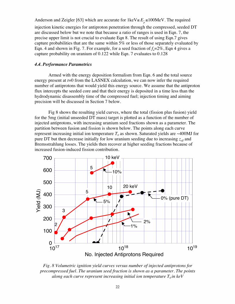
Fig 8 shows the resulting yield curves, where the total (fission plus fusion) yieldfor the 5mg (initial unseeded DT mass) target is plotted as a function of the number ofinjected antiprotons, with increasing uranium seed fractions shown as a parameter. Thepartition between fusion and fission is shown below. The points along each curverepresent increasing initial ion temperature T0 as shown. Saturated yields are ~400MJ forpure DT but then decrease initially for low uranium seeding due to increasing zeff andBremsstrahlung losses. The yields then recover at higher seeding fractions because ofincreased fusion-induced fission contribution.
Fig. 8 Volumetric ignition yield curves versus number of injected antiprotons forprecompressed fuel. The uranium seed fraction is shown as a parameter. The points
along each curve represent increasing initial ion temperature T0 in keV
1017 1018 1019
No. Injected Antiprotons Required
0
100
200
300
400
500
600
700
Yie
ldHM
JL
5
20 keV5
10
10 keV
3
2
0% (pure DT)
2%1%
5%
10%
23
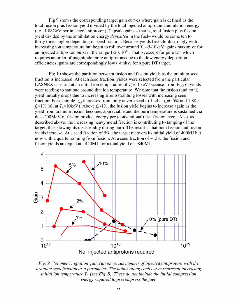
Fig 9 shows the corresponding target gain curves where gain is defined as thetotal fusion plus fission yield divided by the total injected antiproton annihilation energy(i.e., 1.88GeV per injected antiproton). Capsule gains – that is, total fusion plus fissionyield divided by the annihilation energy deposited in the fuel– would be some ten tothirty times higher depending on seed fraction. Because yields first climb strongly withincreasing ion temperature but begin to roll over around To ~5-10keV, gains maximize foran injected antiproton burst in the range 1-2 x 10¹⁷. That is, except for pure DT whichrequires an order of magnitude more antiprotons due to the low energy depositionefficiencies; gains are correspondingly low (~unity) for a pure DT target.
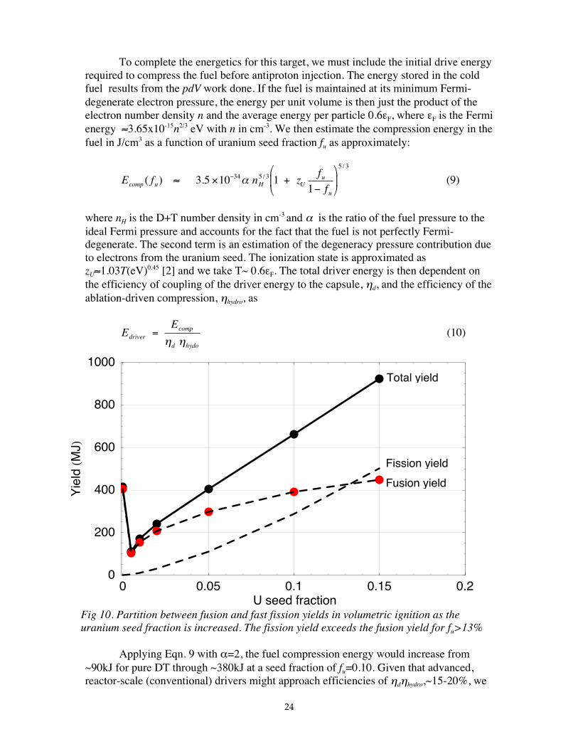
Fig 10 shows the partition between fusion and fission yields as the uranium seedfraction is increased. At each seed fraction, yields were selected from the particularLASNEX case run at an initial ion temperature of To=10keV because, from Fig. 6, yieldswere tending to saturate around that ion temperature. We note that the fusion (and total)yield initially drops due to increasing Bremsstrahlung losses with increasing seedfraction. For example, zeff increases from unity at zero seed to 1.44 at fu=0.5% and 1.88 atfu=1% (all at To=10keV). Above fu~1%, the fusion yield begins to increase again as theyield from uranium fission becomes appreciable and the burn temperature is sustained viathe ~200MeV of fission product energy per (conventional) fast fission event. Also, asdescribed above, the increasing heavy metal fraction is contributing to tamping of thetarget, thus slowing its disassembly during burn. The result is that both fission and fusionyields increase. At a seed fraction of 5%, the target recovers its initial yield of 400MJ butnow with a quarter coming from fission. At a seed fraction of ~13% the fission andfusion yields are equal at ~420MJ, for a total yield of ~840MJ.
Fig. 9 Volumetric ignition gain curves versus number of injected antiprotons with theuranium seed fraction as a parameter. The points along each curve represent increasing
initial ion temperature T0 (see Fig. 8). These do not include the initial compressionenergy required to precompress the fuel.
1017 1018 1019
No. injected antiprotons required
0
1
2
3
4
5
6
Gai
n
10%5%
2%
1% 0% (pure DT)
24
To complete the energetics for this target, we must include the initial drive energyrequired to compress the fuel before antiproton injection. The energy stored in the coldfuel results from the pdV work done. If the fuel is maintained at its minimum Fermi-degenerate electron pressure, the energy per unit volume is then just the product of theelectron number density n and the average energy per particle 0.6εF, where εF is the Fermienergy ≈3.65x10⁻¹⁵n2/3 eV with n in cm-3. We then estimate the compression energy in thefuel in J/cm3 as a function of uranium seed fraction fu as approximately:
E f n zf
fcomp u H Uu
u
( ) . /
/
≈ × +−
−3 5 10 1
134 5 3
5 3
α (9)
where nH is the D+T number density in cm-3 and α is the ratio of the fuel pressure to the
ideal Fermi pressure and accounts for the fact that the fuel is not perfectly Fermi-degenerate. The second term is an estimation of the degeneracy pressure contribution dueto electrons from the uranium seed. The ionization state is approximated aszU≈1.03T(eV)0.45 [2] and we take T~ 0.6εF. The total driver energy is then dependent onthe efficiency of coupling of the driver energy to the capsule, ηd, and the efficiency of theablation-driven compression, ηhydro, as
EE
drivercomp
d hydo
=η η
(10)
Fig 10. Partition between fusion and fast fission yields in volumetric ignition as theuranium seed fraction is increased. The fission yield exceeds the fusion yield for fu>13%
Applying Eqn. 9 with α=2, the fuel compression energy would increase from~90kJ for pure DT through ~380kJ at a seed fraction of fu=0.10. Given that advanced,reactor-scale (conventional) drivers might approach efficiencies of ηdηhydro,~15-20%, we
0 0.05 0.1 0.15 0.2U seed fraction
0
200
400
600
800
1000
Yie
ldHM
JL
Total yield
Fission yield
Fusion yield
25
would require compression driver energies over a megajoule for higher seeded targetsbefore the antiproton volumetric heating source is applied. Accordingly, for spaceapplications, the parallel use of antiproton-driven ablation drive should be considered;this is described in Section 5 below.
Overall burn energetics from Fig. 10 show that the fusion yield is saturating at~460MJ at higher seed fractions. Because there is a fixed 5mg DT fuel mass, thisrepresents an ultimate fusion burn fraction of ~0.27. At fu=15%, the uranium fuel mass is84mg, so that the specific uranium fission yield is ~6000MJ/g and around 7% of the 238Uis fissioning. Given that uranium is dominating the target mass at higher seed fractions,the specific fission yield per unit mass is effectively constant and the correspondingfission burn fraction will saturate around ~10%. Thus, from space propulsion viewpoint,constant exhaust velocities would also be obtained.
4.5 Volumetric Ignition Design Point
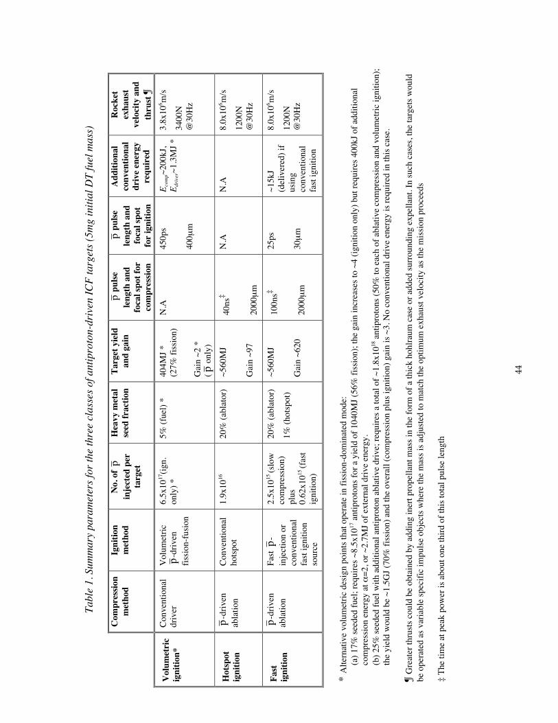
As an example design point, we take a capsule with 5% uranium seed. The massof the fuel capsule is now dominated by the additional 25mg of 238U. Igniting this capsuleat 10keV would result in a total yield of ~405MJ with 27% coming from fission (Fig. 10).The total number of incident antiprotons required to drive this capsule is ~6.5x10¹⁷
resulting in an overall gain of ~2. The separate compression energy would be ~200kJ atα=2 requiring a driver of ~1.3MJ at ηdηhydro,~15%. Given the large number of antiprotonsrequired to drive this class of target and the resulting low gains, we conclude below thatp-driven fission-fusion volumetric ignition targets offer little promise compared to otherpotential options.
For space propulsion applications, the average exhaust velocity provided by thetarget after ignition and burn has occurred is
< > ≈VE
mrocketexhaust
ch ed JET
fuel
2 arg ε(11)
where Echarged is the energy from the fission+fusion target yield in charged particle formwhich is this is distributed over escaping prompt fusion burn products and thermalizedtarget debris, and εJET is the jet efficiency for the spacecraft’s engine and nozzle systems.The latter accounts for the projection of velocities onto the rearward thrust vector, as wellas other efficiencies in forming the exhaust. From the LASNEX burn calculation, 215MJof the 404MJ total yield appears as charged particles including all of the 27% fissionyield; the balance is lost as escaping fast neutrons which do not contribute to directedthrust. The resulting average particulate velocity is ~3.8x10⁶m/s with an average particleenergy of ~1.06MeV. Such particles must be directed into a rearward exhaust, whichintroduces the above jet-efficiency factor.
Because of the low target mass, the impulse per target is only ∆mv = F.∆t~113√εJET N.s which, at a rep-rate of, say, 30Hz translates to a thrust of ~3400√εJET N.Such targets would be employed in the later stages of a mission where high exhaustvelocities are required. For earlier stages, a propellant mass mprop could be added to the
26
target to increase thrust while matching the exhaust velocity to the optimum required toleave the exhaust at rest in the mission center-of-mass. In such a case, the thrust andexhaust velocity would scale as ~√mprop and ~1/√mprop respectively. For targets describedbelow, such mass could be in the form of a thick hohlraum case plus up to ~50g of masssurrounding the target (i.e., expellant). For large payload missions, larger yield targetswould be required [9]. Accordingly, gain scaling is discussed in Section 6 below.
Note, that greater than 1GJ yields will result for seed fractions in excess of 0.17,with >55% of the energy coming from fission. One advantage of running a volumetricallydriven target in this fission-dominated mode at high fu is that approximately the samenumber of antiprotons in the range ~9 x 10¹⁷ are required to initiate such targets,effectively independent of the initial mass (Fig. 8) – at least up to seed fractions of a fewtens of percent – with a corresponding increase in gains and yields. Of course, morecompression energy is required because of the higher initial uranium density (i.e., highermass in the same compressed radius). For example at fu=0.17% (~1GJ total yield) thecompression energy is ~400kJ, which requires an additional 2.7MJ driver atηdηhydro,~15%.
5. ANTIPROTON-DRIVEN HOTSPOT IGNITION
5.1 Hotspot Ignition Physics
Here we examine ICF hotspot ignition with direct p ablative drive. The principlewas introduced in Section 3.3 above and shown in Fig. 4. As with volumetric ignition, aheavy metal seed is required to enhance antiproton energy deposition. In this case the238U seed is placed only in the ablator and not in the fuel itself. This results in clean DTfuel and, because only a small fraction of the fuel is initially heated to ignitiontemperatures, less incident antiprotons will be required per target resulting in highergains. However, unlike the volumetric target, there will be no effective contribution to thetarget yield from fusion-induced fission because the uranium seed in the ablator will haveblown out to low densities before the DT fuel ignites.
The target design consists of a central region of low density DT gas surroundedby a thin spherical shell of solid DT fuel and an outer ablator (Fig. 4). We have selected238U-seeded DT as the ablation material for analysis but combinations of the heavy metalwith other light matrix materials – e.g.,CH plastic, beryllium, etc – are possiblecandidates. A fraction of the antiproton annihilation energy is deposited in the ablatorand, as shown below, the heated plasma expands outwards with velocities of d107cm/s;these are somewhat lower exhaust velocities than encountered for conventional laserdirect drive. By momentum conservation, the remaining portion of the capsule is driveninwards, compressing and heating the DT fuel via shocks and PdV work, and, at peakantiproton drive power – that is, peak injection rate – an approximately uniformacceleration should pertain.
After peak implosion velocity, the shell stagnates on the gas at the center,converting kinetic energy to pressure. The now subsonic capsule relaxes to anapproximate pressure equilibrium with a high temperature, low density hotspotcomprising a few percent of the mass, surrounded by the bulk of the cold fuel at high
27
density. If the hotspot can be created with a temperature of Tignt10keV over a region oflocal areal density of (ρR)ign~0.3g/cm2, then energy deposition per unit volume fromenergetic 3.5MeV alpha particles from the DT fusion reaction will exceed energy lossfrom Bremsstrahlung and electron heat conduction. Under such conditions, athermonuclear burn wave can propagate radially outwards into the cold dense fuel withthe overall burnup determined by the total ρR of the assembled fuel [2]. If the ablator hasbeen completely ablated at the time of peak implosion velocity and the fuel is kept nearlyisentropic, Herrmann et al [11] have shown that the implosion dynamics can becharacterized by four parameters: the fuel mass, the ablation pressure, the in-flightadiabat (i.e., the ratio of the in-flight fuel pressure to the irreducible Fermi degeneratepressure) and the peak implosion velocity. In particular, several studies have highlightedthe critical dependence of ignition threshold on the achievable peak implosion velocity[2,11,64-66]. The two major parameters of interest here for antiproton-drive hotspotignition, i.e., ignitability and yield, are then a function of these four parameters and,therefore, on the number of injected antiprotons.
In general, the energy that must be delivered to a spherical capsule to createignition conditions scales as
Evign
x
xhydro
~α
η
1
2
where v is the peak implosion velocity, α is the fuel adiabat parameter and ηhydro, is thehydrodynamic efficiency of coupling the absorbed drive energy into stored compressionenergy [2,11,64-66]. Based on the two region, isobaric target model of Meyer-ter-Vehn[67], an early study [64] suggested exponents of x1~3 and x2~10. Numerical calculationsby Levedahl and Lindl [65] that accommodated 1-D transport refined this to x1~3/2 andx2~5. Recent work by Herrmann et al. [11] et al for a suite of LASNEX runs showed thatx1~2.66 and x2~7.21 providing α is taken to be the adiabat in the stagnated fuel (typicallygreater than the in-flight adiabat α if due to the interaction of reflected shocks). Byexplicitly including the drive pressure P, they arrived at a general ignition scaling law interms of α if as
Ev Pign
if
hydro
~.
. .
α
η
1 88
5 89 0 77 (12)
Note the high inverse dependence of ignition energy on achievable peak velocity.It is now believed that to maintain targets on acceptably low adiabats, peak implosionvelocities obtainable with conventional drivers will be limited to about 3-4x107cm/sbecause of hydrodynamic instabilities and maximum attainable drive pressures [2].
5.2 Analysis and Results
In this study, we will not resort to a full 1D radiation-hydrodynamics-burncalculation, not least because we have no formal models for antiproton ablation drive in
28
our present codes. Instead, because of the primacy of implosion velocity in determiningignitability (Eqn. 12), we model the dependence of this velocity on injected antiprotonflux and thereby estimate the number of injected antiprotons required to drive a typicalhotspot target. Provided the required drive pressure and peak velocity can be obtained,then, to zeroth order, we might expect the burn dynamics to proceed similar to that of aconventionally-driven target.
We take a 5mg DT fuel mass with inner radius of 0.178cm and initial shellthickness of 0.040cm at an uncompressed cryogenic solid density of 0.25g/cm3. Thesedimensions were scaled from a high gain reactor target we are presently studying forconventional direct drive [6]. The fuel is surrounded by a 238U-seeded DT ablator of shellthickness 0.032cm with DT mass of 5.4mg. The kinetic energy of the incidentantiprotons is adjusted so that they have a slowing down range in the ablator equal to theaverage fission product range <Rfp> of the fragmenting uranium seed nuclei. Thethickness of the annihilation energy deposition region and therefore, the approximatethickness of the ablation front, is then ~2<Rfp>. By analogy with Eqn. 6 above, theenergy deposited in the ablation front per antiproton as a function of the uranium seedfraction fu is then approximately
E f p f p E p fR
REa u u u f f u u
a fp( ) ( ) ( ( ) )( )
≈ < > + −< >
< >1ρ
ρ ππ (13)
where ρa is the average density across the ablation front.
We estimate the range <Rfp> of antiproton-induced fission fragments in theseeded ablator using a empirical fit to fission product range data [68,69] as
< > ≈ +< >
RM
z
M E
zfpf f
f a
( . . )/
/ /
/0 0968 0 0497 1 2
1 2 1 2
3 2ρ(14)
where M and z are the mass number and atomic number of the stopping medium, and Mf
and zf are the mass number and atomic number (i.e., bare charge) of the fission fragment.This is an average over all light and heavy fragments characterized by an average energy<Ef>. The range <Rfp> is in units of cm for <Ef> in Mev and ρa in mg/cm3.The charge state of the fission fragment as it slows is accommodated by the empirical fitcoefficients of Eqn. 14 but is taken to scale with velocity vf as q(vf)~20(vf/vfo)
1.1 where vfo
is the initial velocity corresponding to an energy <Ef> [68].
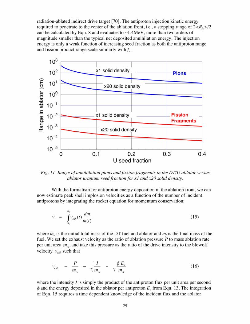
As an example, in Fig. 11 we plot the ranges of antiproton-induced 238U fissionfragments and DT annihilation pions in the ablation front as a function of the ablator seedfraction. The methodology for determining pion ranges was described in Section 4above. The ranges are shown for densities of one and twenty times solid density; suchdensities span the time-dependent range we typically see at the ablation front during 1-Dcompressions of conventional high yield reactor targets [6,70]. From Fig. 11, assumingthat fission product deposition is dominating the net energy deposition (a goodassumption for fu>1% – see Fig. 7 above) the thickness of the antiproton-driven ablationfront is seen to be in the vicinity of ten microns, comparable to that of a conventional,
29
radiation-ablated indirect drive target [70]. The antiproton injection kinetic energyrequired to penetrate to the center of the ablation front, i.e., a stopping range of 2<Rfp>/2can be calculated by Eqn. 8 and evaluates to ~1.4MeV, more than two orders ofmagnitude smaller than the typical net deposited annihilation energy. The injectionenergy is only a weak function of increasing seed fraction as both the antiproton rangeand fission product range scale similarly with fu.
Fig. 11 Range of annihilation pions and fission fragments in the DT/U ablator versusablator uranium seed fraction for x1 and x20 solid density.
With the formalism for antiproton energy deposition in the ablation front, we cannow estimate peak shell implosion velocities as a function of the number of incidentantiprotons by integrating the rocket equation for momentum conservation:
v v tdm
m texh
m
m
o
f
= ∫ ( )( )
(15)
where mo is the initial total mass of the DT fuel and ablator and mf is the final mass of thefuel. We set the exhaust velocity as the ratio of ablation pressure P to mass ablation rateper unit area «mA, and take this pressure as the ratio of the drive intensity to the blowoffvelocity vexh such that
vP
m
I
m
E
mexhA A
a
A
= ≈ =« « «
φ(16)
where the intensity I is simply the product of the antiproton flux per unit area per secondφ and the energy deposited in the ablator per antiproton Ea from Eqn. 13. The integrationof Eqn. 15 requires a time dependent knowledge of the incident flux and the ablator
0 0.1 0.2 0.3 0.4U seed fraction
10-5
10-4
10-3
10-2
10-1
100
101
102
103
Ran
gein
abla
tor
Hcm
L
x1 solid density
x20 solid density
x1 solid density
x20 solid density
Pions
FissionFragments
30
density ρa. As we are only seeking typical integral performance parameters and are notperforming a self-consistent 1D compression, we do not attempt to formally evaluate atemporal shape for the antiproton pulse. Instead, we assume a generic pulse shape andtime-dependent average density across the ablation front as:
φ
φ
φ
φ
( )
. √
√( . . )
√
t
t t
t t
t tt t t
t t t
=
< ≤
−−
+ < ≤
< ≤
0 08 0
0 92 0 08
1
1
2 11 2
2 3
(17)
ρ ρa att t ns( ) ( . )= ≤ ≤0 1 06 0 40 (18)
these being scaled from a representative 1-D simulation of a conventional indirect-drivecapsule with comparable dimensions and total yield and approximately comparableexhaust velocities and ablation front widths [70]. Here t1=24ns, t2=32ns, t3=40ns and ρa0
is the uncompressed density of the ablator at t=0. The time integral of Eqn. 17 thereforeyields the total number of antiprotons required per unit area to drive the capsule to a peakimplosion velocity v evaluated by Eqns. 15 and 16.
In Fig 12 we plot contours of peak implosion velocities attainable for a given totalnumber of incident antiprotons as a function of the uranium seed fraction in the ablator.Note the very large number of antiprotons required at low seed fraction because of theminimal energy deposition of annihilation pions in the ablator. We might also expectsignificant relative preheating of the fuel by these pions in this regime that may precludehigh fuel compression on a low adiabat. Given the achievable velocity is a balancebetween adequate energy deposition in the ablator and decreasing exhaust velocity athigher ablator masses , we see a broad maximum in the peak inward shell velocity for afixed number of injected antiprotons around a seed fraction of fu~0.2.
The corresponding average ablator exhaust velocities can be mapped onto thespace of Fig. 12 and these are shown in Fig.13. Here, for a given antiproton number,maximum exhaust velocities are attainable for seed fraction of fu~0.03 where the rocketefficiency is a maximum (see below). The broad maximum in peak implosion velocitiesat the higher 0.2 seed fraction seen in Fig 12 above then results from the logarithmicdependence on ablated mass from the rocket equation, i.e., v v m mexh f~ ln( / )< > 0
5.3 Hotspot Ignition Design Point
We can obtain an approximate design point by selecting a desired peak shellvelocity of, say, 3x107cm/s. The kinetic energy at peak velocity for the 5mg fuel shell isthen ~2.25x10⁵J. If we assume that this stagnates into a hotspot at the ignitiontemperature of Tign~10keV containing approximately 2% of the total fuel mass, typical foran isobaric hotspot target [67], then the energy in the hotspot is ~1.15 x10⁵J leaving ~1.1x10⁵J compressional stored energy in the surrounding cold fuel. At a stagnation adiabatof αstag~3, the target would have an areal density of ρR~3 and, by Eqn. 1, a fuel burnup ofaround one third. For 5mg of DT, this represents a fusion yield of ~560MJ.
31
Fig. 12 Contours of peak shell implosion velocity as a function of number of injectedantiprotons and ablator uranium seed fraction. A broad minimum in the required number
of antiprotons for a given peak velocity is seen around fu~20%
Fig. 13 Contours of average ablator exhaust velocity as a function of number of injectedantiprotons and ablator uranium seed fraction. Exhaust velocities maximize for a given
injected antiproton number around fu~3% where the rocket efficiency is a maximum
0 0.1 0.2 0.3 0.4U seed fraction
1014
1015
1016
1017
1018
No.
inje
cted
antip
roto
nsre
quire
d
0.5
1
2
34
5
Peak implosion velocity(107cm/s)
0 0.1 0.2 0.3 0.4U seed fraction
1014
1015
1016
1017
1018
No.
inje
cted
antip
roto
nsre
quire
d
0.1
0.2
0.5
1
2
Average ablator exhaust velocity (107cm/s)
32
In Fig. 14, we plot a gain curve for the fixed fuel mass of 5mg as a function ofablator seed fraction by using data corresponding to the v=3x107cm/s contour in Fig 12,and where we define gain as the fusion yield from above (~560MJ.) divided by the totalrest mass energy available in the injected antiprotons (1.88GeV per antiproton). We alsoplot the ideal hydrodynamic (rocket) efficiency in Fig. 14 where
ηhydro uf o u f o u
f o u
fm m f m m f
m m fv cm s
( )( / ( )) ln[ / ( )]
/ ( )/
≈−
= ×
2
713 10
(19)
Fig 14. Gain curve and ideal hydrodynamic (rocket) efficiency for antiproton-drivenhotspot ignition at 3x107cm/s peak implosion velocity as a function of ablator uraniumseed fraction. Peak gains approach 100 at fu~20%. (Peak gains for fast ignited targets
are ~600 at the same ablator seed fraction – see below). The rocket efficiency is amaximum at fu~3% where maximum exhaust velocities are obtained
Antiproton drive should be closer to this ideal efficiency than conventional driversbecause, unlike laser or radiation drive, minimal kinetic energy is expended in transitingthe ablation exhaust relative to the annihilation energy deposited at the ablation front. Inparticular, the antiproton kinetic energy lost in penetrating to the ablation front is only~1.4MeV, whereas the energy deposited there is some 10-20% of the total 1.88GeVannihilation energy, depending on seed fraction (see Fig. 7). Radiation energy loss athigher uranium seedings will, however, reduce actual efficiencies from these ideal values.
The peak gain occurs at a seed fraction of fu~0.2 where the minimum number ofantiprotons is required for a given peak implosion velocity (see Fig.12). By contrast, themaximum rocket efficiency occurs at a seed fraction of only ~0.03 where exhaust
0 0.1 0.2 0.3 0.4U seed fraction
0
20
40
60
80
100
Gai
n
Gain
Rocketefficiency x100
33
velocities maximized (see Fig. 13), a consequence of the fact that hydrodynamicefficiency is defined in terms of antiproton annihilation energy deposited, while gain isdefined in terms of antiproton annihilation energy injected. As shown, peak gainsapproaching 100 may be obtainable for this hotspot target– an order of magnitude higherthan those for volumetric ignition above – but still requiring the injection of some 2x10¹⁶
antiprotons per target (Fig. 12). Scaling of the targets to higher yields and gains will bediscussed below.
5.4 Target Stability
For a given antiproton-driven ablation pressure P, a larger radius, thinner shellenclosing more volume could be driven to a higher final velocity than a thicker shell ofthe same mass. However, there is a limit on the aspect ratio of the shell thickness toradius determined by the Rayleigh-Taylor fluid instability [2,71]. If the in-flight aspectratio (IFAR), is defined as the ratio of the shell thickness ∆Ro to its radius R0 as it beginsto accelerate (this is less than the initial thickness because the shell is subsequentlycompressed) then, using the scalings in Ref. 2, this can be related to the implosionparameters above as
where C is a constant. Note the quadratic dependence on implosion velocity. Stabilitytypically dictates an upper limit of ~35-45 on IFAR otherwise shell breakup will occur atlate time and hotspot formation will be prevented.
We will not consider stability formally in this paper even though it is an importanttopic for overall target performance. In general, we note that the antiproton-drivenimplosions are high ablation rate, low exhaust velocity implosions. They are thus moreakin to conventional radiation-driven, indirect drive implosions [70, 72] thanconventional laser direct-drive implosions [6,71] and have comparable ablation frontthickness. Therefore, stability may be acceptable providing low mode asymmetries due tononuniform antiproton injection can be minimized. If the latter proves problematic, thenthe semi-indirect-drive target outlined in Section 3.3 might be a better design candidate.
6. ANTIPROTON-DRIVEN FAST IGNITION
6.1 Fast Ignition Rationale
In the hotspot target above, the energy contained in the hotspot at ignition scalesas the hotspot mass and temperature as ~ R T R THS HS ign ign ign HS
3 3 2ρ ρ ρ= ( ) / , i.e., inversely
with the square of the attainable density for given ignition condition of (ρR)ign and Tign..By contrast, the compression energy in the fuel scales as ~αρ2/3 (Section 5). Thus, thesum of the ignition and compression energy could be reduced if the capsule is assembledto an approximately uniform density that is higher that the hotspot density but lower than
34
the cold fuel density, followed by subsequent ignition of an outer portion of the fuel by aseparate fast energy source.
Antiprotons could be used in fast ignition as the ablative drive system to compressthe fuel in a manner similar to hotspot ignition above but with relaxed timing constraints.In principle, they could also be used as the fast energy source for the ignition spot. Asshown below, the latter is faced with stringent requirements in terms of injection timesand aiming precision, so antiprotons may have more utility to just drive the much relaxed,slow compression phase of fast ignition. In such case, a separate conventional fast energysource such as a short pulse laser would be needed to spark the ignition.
6.2 Fast Ignition Hotspot Creation
A propagating burn under the isochoric (constant density) conditions of fastignition requires ignition conditions of Tign ~10keV over a local areal density of(ρR)ign~0.5g/cm2 (Section 3.4). Once the density of the ignitor region is specified, thisrepresents a specific deposited energy. Accordingly, the required number of antiprotonsdelivered to the ignitor spot to create these conditions is approximately:
N fR T
f E fp u fast
ign ign
HS u net u
( )( )
( ) ( )≈ ×3 1021
3
2
ρ
ρ(21)
where Enet (Mev) is the net energy deposition in the hotspot per antiproton and where, forfast ignition, the hotspot density is of the order of the bulk fuel stagnation densityρHS~ρstag (g/cm3).
Heavy metal seeding of the ignitor core (but not the bulk fuel) is presumablyrequired otherwise the local deposition of annihilation energy is minimal. At a seedfraction of fu=0.01, the net deposition fraction per antiproton is ~3.6% , i.e. 70MeV(Fig 7). Thus, if the overall DT fuel is initially compressed to say, 100g/cm3 by theseparate slow compression system, the ignitor core with its 1% uranium seed will be atρHS~200g/cm3, and by Eqn. 21 will require a minimum ~1.4x10¹⁵ delivered antiprotonsfor a hotspot spark energy of ~15kJ. A caveat, however, is that the minimum ρRignTign
conditions for fast ignition burn propagation may be higher with heavy metal seedingpresent due to increased Bremsstrahlung losses from the hotspot. Secondly, ionization ofthe 1% uranium seed at the ignition temperature of10keV will contribute additionalelectrons to the hotspot, thus increasing the heat capacity over that implied in Eqn. 21.(e.g., with the estimation of the ionization state of uranium zU used in Eqn 9 above, the zeff
of the hotspot will be ~1.6 at fU=1% and the delivered antiprotons requirement wouldincrease to ~2.2 x10¹⁵).
6.3 Slow Compression Drive
We now examine how antiprotons could be applied to drive the slow compressionphase of fast ignition. The fast ignition source could then be either a fast antiproton burstas described above, or a conventional fast energy source such as a short pulse laser. Aswith hotspot ignition above, we take the peak attainable shell velocity as the datumparameter of interest. Here, however, the shell kinetic energy is only required to convert
35
to a rather modest stagnation density under isochoric conditions, rather than to create theignition hotspot energy and high density compressed fuel.
In their study of radiation-driven capsules for fast ignition, Slutz and Herrmann[53] provide a scaling of stagnation density in g/cm3 as
ρ αstag v≈ × { }−6 10 20 3/ (22)
where v is the peak implosion velocity in cm/s. This is obtained by taking the peakkinetic energy of the imploding shell to be adiabatically converted to internal energy. Itassumes a uniform final density whereas hollow profiles may be hard to avoid in practice[73]
Peak shell velocities for antiproton ablative drive to achieve this stagnationdensity can then be obtained by the methodology of Section 5 as a function of the numberof incident protons. Thus, in general, the total optimum number of antiprotons to igniteand burn a fast ignition capsule is a minimization over those required for both the slowcompression drive and the fast ignition spark as:
N f f N f N fp stag u a u s p stag u a comp p u s fast( , , ) ( , ) ( ), , , ,ρ ρ= + (23)
where ρstag is the fuel stagnation density, and fu,a, fu,s are the seed fractions in the ablatorand fast ignition core, respectively.
6.4 Fast Ignition Design Point
As an example of applying Eqn. 23, we take a design similar to the hotspotcapsule above with 5mg of DT fuel – unseeded, except for the designated hotspot regionif antiproton fast ignition is also to be employed – and an outer 238U-seeded DT ablator(Fig. 5). We appreciate that it may be difficult in practice to seed the hotspot region andnot seed the main fuel, both as an issue of itself and as something that might affect thesymmetry of the compression. We take a stagnation fuel density of ρstag=150g/cm3 which,by Eqn (22), necessitates a peak implosion velocity of ~1.6x107cm/s at, say, α=1.5. Fromthe methodology of Section 5 above, this velocity can be obtained with a minimumnumber of ~ 2.5x10¹⁵ injected antiprotons at an optimum ablator seed fraction of fu,a ~0.2 (Fig. 12). From Eqn. 21, the fast ignition of the hotspot – assumed to be separatelyseeded at, say, fu,s=0.01 for a total density of ρHS~300g/cm3 – requires ~0.62x10¹⁵ fastinjected antiprotons.
The total of ~3.1x10¹⁵ fast and slow injected antiprotons for this fast ignitiontarget is a factor of six lower in number and rest mass energy than that required for thehotspot ignition capsule above – or, a factor of eight if a separate, conventional energysource is employed to supply the fast ignition spark – and is demonstrative of the lowervelocities required to assemble the fuel. Given that this target has around the same totalareal density of ρR~3g/cm2 as the hotspot capsule (because of the density gradient of thelatter) and, therefore, around the same fusion yield of ~560MJ, the fast ignition gains willbe higher by the same ratio. In this case, the ratio of fusion yield to the total energy
36
annihilation available in the delivered antiprotons would be ~600, up from the gain of~100 for hotspot ignition.
The isotropic particulate velocity of this target for space propulsion applications is~8.0x10⁶ m/s with an average particle energy of ~0.84MeV. The corresponding targetimpulse is ~40√εJET N.s which, at a rep-rate of, say, 30Hz translates to a thrust of~1200√εJET N. Addition of inert propellant mass mprop in the form of a thick hohlraumcase (and perhaps up to 50 g of additional expellant) would scale the thrust and exhaustvelocity as √mprop and 1/√mprop respectively. The total target mass could be varied aboutsome mean value thus offering a variable specific impulse rocket with optimum exhaustvelocity.
High payload space missions will probably require higher yield targets (see, forexample, Ref 9). For conventional hotspot targets, as the driver energy Edriver increases,the minimum velocity required to ignite the capsule decreases. If the minimum velocity atany driver energy is exceeded, the capsule will still ignite but the gain – i.e., the ratio ofthe fusion yield to Edriver – will drop. The optimum strategy implies operating near theminimum implosion velocity consistent with desired yield or driver size. Accordingly,optimum gain curves follow a typical scaling of ~ Edriver
γ where γ≈0.6-0.8 [1,2]. Ourhotspot target in Section 5 and the slow compression phase of the fast ignition target hereimplode in a manner analogous to that of conventional high yield ICF capsules.Furthermore, like laser or radiation drive, the physics of antiproton deposition for ablativecompression is governed by micron-size scalelength processes at the ablation front,effectively independent of the total yield. Thus, to a zeroth order, we might expect thatgains will scale in a manner similar to those for conventional targets, offering anapproximate yield scaling with number of injected antiprotons N p as
Y NN
Npp
p
( ) ≈
+
5600
1 γ
(24)
where Y is the fusion yield in MJ, γ≈2/3 and N p 0 ≈3.1x10¹⁵ or ≈1.9x10¹⁶ for p-driven
fast ignition or hotspot ignition targets, respectively
In the VISTA ICF space propulsion study of Ref. 9, a 100tonne payloadtransported to Mars utilized laser-driven capsules with 7.5GJ yields and a total number of8x107 targets. Accordingly, scaling our nominal 0.5GJ hotspot or fast ignition targets byan order of magnitude in yield to 5.6GJ, might require an increase in injected antiprotons
for ablative drive by a factor of ~10 1 1( )+ −γ . This translates to ~1.2x10¹⁶ and ~7.6x10¹⁶ p for5.6GJ fast ignition and hotspot capsules, respectively. For mission parameters similar toVISTA, several moles of onboard stored antiprotons might therefore be required
7. TIMING AND AIMING REQUIREMENTS FOR ANTIPROTON INJECTION
The maximum antiproton injection time to create the fast ignition hotspot inSection 6 must be of the order of the hotspot disassembly time otherwise fuel expansionwill quench the burn before it propagates into the cold fuel. If we represent this by the
37
sound transit time across the hotspot at the ignition temperature Tign, then the requiredinjection time is τign~RHS/cs(Tign), resulting in a required antiproton injection time of~25ps. With a required injection of 0.62x10¹⁵ antiprotons into the hotspot (Section 6.4),this represents a peak current of ~3.9MA. Similarly, with a deposition region set to~2RHS = 2(ρR)ign,/ρHS , where ρHS ≈ρstag, this case requires focal spot diameters of ~30µmon the outside of the compressed fuel. These are formidable requirements for a focused,accelerated beam of z=1 particles at kinetic energies of ~1MeV
By contrast, the injection requirements to drive the slow compression phase offast ignition are considerably relaxed relative to the ignition phase, and also whencompared with drive specifications for hotspot ignition under isobaric conditions. Ingeneral, comparing the ablative drive requirements for this slow compression phase(Section 6.3) with those for hotspot ignition (Section 5) we would expect the penetrationtime for the first low intensity shock to be greater because fast ignition capsules wouldtypically be designed with a thicker, more massive shell. Second, the implosion velocitiesare relaxed, viz. t1x107cm/s rather than t3x107cm/s for hotspot ignition. Third,compressed core radii are bigger due to the lower final density requirements, thus shellconvergence ratios C will, in general, be lower. Here, we might expect pulse lengths forthe slow compression phase for fast ignition to scale as t~C/v. Accordingly, whereas our5mg hotspot targets required a drive pulse length in the vicinity of ~40ns (or ~10ns atpeak power), this relaxes for the slow compression phase for the fast ignition target to~100ns (or ~30ns at peak power). With a required injection of 2.5x10¹⁵ p to drive theslow compression phase (Section 6.4), this translates to an antiproton injection current of~4kA. For the ablative drive phases of both fast ignition and hotspot ignition, the focalrequirements are of the order of the target diameter under compression, an increase ofsome sixty-fold over the antiproton injection focal spot diameter required at the fastignition hotspot.
In the case of fission-fusion volumetric ignition (Section 4), the antiprotonignition source is applied after the fuel is compressed but, unlike fast ignition, isdistributed across the whole compressed core rather than just at the hotspot. Moreover,ignition temperatures can be lower than hotspot-ignited targets while the seeded fuelmass has higher densities; hydrodynamic expansion is correspondingly slower. As above,we assume that this ignition energy is deposited in a time less than the disassembly timeof the compressed fuel, requiring an injection pulse length of τ ~Rfuel/cs(Tign,fu) across thecompressed fuel radius Rfuel. For our design point in Section 4 above for a 5mg DT fuelmass with, say, a fu=5% uranium seed fraction, this translates to τ∼450ps, intermediatebetween the injection times for ablative compression and fast ignition of a hotspot. Therequired antiproton focal spot diameter is of the order of the compressed fuel diameter.i.e., ≈2Rfuel =2(ρR)fuel /ρfuel ~400µm.
In summary, total pulse length requirements and, therefore, antiproton injectiontimes for the concepts in this paper scale as:
τ τ τ τfastign
HS
s ignvolumetricign
fuel
s ign uhotspotign
hotspotign
hotspotign
slowcomp
fastign
fastign
R
c T
R
c T f
C
v
C
v~
( )~
( , )~ ~<< << <
38
For the 5mg DT target designs above, τ fastign
~25ps, τ volumetricign
~ 450ps (at fu=5%),
τ hotspotign
~40ns (or ~10ns at peak power), τ slowcomp
~100ns (or ~30ns at peak power)
Similarly, focal spot diameters for antiproton injection scale as
dR
dR
d R d Rfastign
ign
HS stagvolumetricign
fuel
fuelhotspotign
slowcomp
~( )
( )~
( )~ / ~ /
2 22 2 2 20 0
ρ
ρ ρ
ρ
ρ≈<< << ≈
For the target design points above, d fastign
~30µm, dvolumetricign
~ 400µm, dhotspotign
≈ dslowcomp
~2000µm
8. ANTIPROTON PRODUCTION, STORGE AND INJECTION
It is beyond the scope of this paper to formally assess the systems issuespertaining to the production and manipulation of antiprotons for projected applicationssuch as space propulsion. However, given the arguable practicalities for a potential futuretechnology that today is still in a basic science phase [14-29], it behooves us to considersome fundamental requirements. We note that one of us (CDO) has addressed thedetailed systems issues for conventional, laser-driven ICF space propulsion [9].
Today, antiprotons are routinely produced at the world's large proton synchrotronsand are subsequently utilized for particle physics research in high energy proton-antiproton colliders. Production takes place by accelerating protons onto a cooledtungsten target according to the reaction:
p p p p p p+ → + + +
This minimum set of product particles is necessary for baryon conservation and thethreshold energy is 5.63GeV for a stationary target. For production in a future center-of-mass collider, the threshold would be just twice the proton rest mass, i.e.,1.88GeV.Energies greater than threshold are required for an adequate yield and peak productionrates occur around ~200GeV. The resulting antiprotons are directed by a magnetic lensand, following cooling to reduce energy spread, are decelerated to several tens tohundreds of MeV and collected in storage rings.
The ACOL antiproton production facility at CERN can produce >1012 p/day, andthe Low Energy Antiproton Ring (LEAR) stores antiprotons at ~200MeV with a finalenergy spread of <<3% [74]. We note that the goals of the world’s high energy physicsprograms are typically satisfied with a modest production of only ~ few x1015 p/year,about the number required to drive just one high yield ICF target above! Antiprotonproduction efficiency – that is, the ratio of stored antiprotons to accelerated incidentprotons – on these unoptimized systems is rather low, i.e. ~10--4. And, given that suchantiprotons are employed as mere engineering tools to facilitate particle physics researchprograms, high production rates are neither desired nor sought. Clearly, for practicalapplications, a scale-up of production by orders-of-magnitude would be required,
39
together with commensurate increases in production efficiencies; candidate methods toachieve this are discussed in Ref. 41. Conceivably, antiproton production for deep spaceapplications could take place in large solar-powered production factories in planetary orsolar orbit. However, unlike applications to ICF terrestrial energy production, overallenergy breakeven would not necessarily be required.
The kinetic energies required of the antiproton injectors for targets in this paperneed only be sufficient for penetration to the required annihilation point, i.e.,~1-10MeV,and are typically less than one percent of the useful fraction of annihilation energydeposited in the targets. Of course, antiproton ion sources would need to be developed.The resulting peak beam currents required are
I N ep beam p, /= τ (25)
where τ is the required pulse length. This ranges from kiloamperes for direct ablativedrive to megamperes for sparking fast ignition hotspots, with intermediate requirementsfor volumetric ignition targets (Section 7). Although these beams have much lowerkinetic energies than typical heavy-ion drivers for ICF [72] and lower currents relative totypical pulsed light ion diodes, the low kinetic beam energy Ek will result in a highperveance, K ~ Ip beam, /Ek, that will make it difficult to focus the beam to small spot sizes
without neutralized focusing, i.e., without adding a co-moving positively charged beam.Note that neutralizing an antiproton beam would necessitate adding positrons, notelectrons; this has been attempted in experiments at CERN [16]. An alternative might beto employ plasma channel focusing through a low density, conventional (normal matter)plasma background. The total injected kinetic energy per target is only a few kilojoules;that is, an average power of a few tens of kilowatts at a target repetition rate of, say,10Hz. For space propulsion applications, this minimal recirculating power plus plantauxiliary power requirements could be supplied via a magnetic pickup coil from the mainplasma exhaust stream [see, for example, Ref. 9]. Alternatively, for simplicity andminimum mass, a small dedicated fission reactor could be employed.
Antiprotons have been routinely contained in large storage rings for fractions of ayear. Low energy antiprotons have also been manipulated and transported in portablePenning Traps with storage times of months [14, 15, 17-19]. Holzscheiter et al. [15] havecaptured over one million antiprotons from the LEAR ring at CERN in a large Penningtrap. Surprisingly, when these antiprotons were cooled to energies significantly below1eV, the usual determiner of antiproton storage lifetime – i.e., annihilation on residualgas molecules – fell to anomalously low values which may have significance for futurelong-term storage concepts.
For space applications, antiprotons would be produced in separate, optimizedproduction facilities and the total number required for all targets for a mission would bestored onboard. The limit on the density of antiprotons np stored as a non-neutral, single
ion plasma in a confining magnetic field B is set by the Brillouin limit [75]. Thisexpresses the space charge equilibrium condition between the self field of the antiprotonsrelative to the external field and can be expressed as
40
n m c
Bp p
o
2
2 21
/ µ≤ (26)
That is, the applied axial magnetic field containing the radial electric space charge of thenon neutral plasma must have an energy density greater than the rest mass energy densityof the ions so contained. Brillouin limits arbitrarily close to unity can be obtained inlaser-cooled traps at low temperature [75]. As an example, with, say, a nominal 5x10¹⁵
antiprotons required per target and a maximum practical confinement field of, say, 14T,each target requires an antiproton storage volume of 0.009m3 at the Brillouin limit. Thus,for, say, an inventory of 106 targets, the onboard storage volume for antiprotons in singleion form would be ~9x10³m3, that is a vessel some twenty meters on a side. For Nb3Snsuperconducting magnets and high strength, low temperature stainless steel structure withyield stress of ~800MPa, the vessel mass would be tens of thousands of tonnes assuminga solenoidal trap limited by magnetic hoop stress. This is a significant mass penalty.
The required magnetic confinement field and/or volume and, in particular, vesselmass could be drastically reduced if the antiprotons were stored as a low temperature,neutral plasma of antiprotons and positrons. In this case, the storage limit and requiredmagnetic field would be determined by the macroscopic beta (pressure) equilibrium limit,i.e.
βµ
= ≤2
212
n kT
Bp
o/(27)
where T=Ti≈Te is the plasma temperature. Employment of a field-reversed configuration,might permit beta limits close to unity [56,57]. Note, from Eqs. 26 and 27, that the ratioof the magnetic fields required to contain the antiprotons as a neutral plasma to thatrequired to contain the equivalent number density as a non-neutral plasma is
B
B
kT
m cneutral
nonneutral p
≈2
2 (28)
which, for an ion temperature of, say, T=10eV, is ~10-4, thus underlining the value ofneutralization. Equivalently, at the same 14T field, the storage volume for the same total(5x1015)x106 antiprotons falls to significantly less than a cubic meter and vessel masses toless than a tonne. An external RF heating source would be required to maintain thetemperature of such a neutral plasma against steady-state energy confinement losses.
Antiproton storage in neutral matter form would avoid the high magnetic fieldsassociated with either single ion or plasma containment. Such neutral antimatter would,of course, have to be isolated from normal matter. Experiments at CERN [16] createdantihydrogen atoms by traversing a xenon jet with an antiproton beam. Here, a smallfraction of the antiprotons convert their energy to electron-positron pairs and a fraction ofsubsequent antiprotons pick up the positrons. Recently, Gabrielse et al. [17] formedantihydrogen in an excited state by combining antiprotons and positrons in a Penningtrap, while Amoretti et al. [18], and subsequently Gabrielse et al. [19,20] detected coldantihydrogen by the same method.
41
Long term storage in bulk neutral matter form would require the formation ofanti-molecular-hydrogen, i.e. H2, and not merely antihydrogen. One method tomanipulate bulk antimatter might be in the form of cluster ions, Hn
- , i.e. a cluster of n
antihydrogen atoms with a positron removed. According to Stwalley [76], formation ofanti-H, anti-H+ and anti-H2- could proceed by a number of methods. Molecularantihydrogen, i.e. anti-H2, would be the most difficult of the simple species to form andespecially to manipulate because of small magnetic moments and complex vibrationalstates. However, both the ionic species anti-H2- and anti-H2+ would be stable if formedand, in principle, would be more easily controlled and manipulated via magnetic,electrostatic and RF techniques. Antihydrogen ice formation via inverse sublimationwould require methods for latent heat removal and nucleation that do not involve anormal matter wall. Levitation of antihydrogen ice would depends on its form --orthohydrogen (spins parallel) or parahydrogen (spins antiparallel). The latter isdiamagnetic and might be stably levitated in a static field as has been demonstrated withgraphite of similar diamagnetic susceptibility [77]. Active electrostatic levitation withfeedback position control might also be performed and would require charging of the iceparticles by, say, irradiation with UV light. An analogous trap constructed at the JetPropulsion Laboratory, Pasadena CA, levitated a 20mg ball of H2O-ice in the earth’sgravitational field [78].
9. SUMMARY AND CONCLUSIONS
In this paper, we have examined the physics underlying the use of antiprotons todrive various classes of ICF targets to high yield by the methods of volumetric ignition,hotspot ignition and fast ignition. We have determined the useable deposition fraction ofannihilation energy together with integrated energy balances in the targets and, thereby,deduced the typical number of injected antiprotons required, together with timing andfocal spot requirements. A summary is provided in Table 1.
Volumetric ignition with minimum useful yields (few hundred megajoules, 5mginitial DT mass) results in low gains and requires large numbers of injected antiprotons(~6.5x10¹⁷) in addition to the large precompression energy required to create the initialdense core. This is because the whole compressed fuel is raised to the ignitiontemperature rather than just a local hotspot as in the other classes of target. Note also that,in addition to the large number of antiprotons required for ignition, they must be focusedto a few hundred microns onto a compressed core in a very short time (~few hundredpicoseconds). If such targets are to be employed, it appears advantageous to run them infission-dominated mode, that is with uranium seed fraction above ~15% and yields in thegigajoule range (for 5mg initial DT mass) – see the footnote to Table 1; the overall gainsare, however, still low. Because of the large conventional driver energies required forprecompression, and the fact the antiproton number for ablative compression is alwayslower than that required to promote volume ignition – at least up to a seed fraction of~25% – antiproton ablative drive should also be considered for these targets. Forexample, at fu=25%, a total number of ~1.8x10¹⁸ antiprotons would be required (~50%going to each of ablative compression and volumetric ignition); the yield would be~1.5GJ (70% fission) and the overall (compression plus ignition) gain is ~3.
42
The fact that it requires significantly more energy to heat fusion fuel relative tocompressing it to high density was appreciated early in the ICF program where it wasdetermined that volumetric ignition would probably not lead to high gain fusion. Ingeneral, we conclude that p-driven fission-fusion volumetric ignition targets offer littlepromise compared to the other options – that is, pure fusion targets with antiprotonablative drive and burn propagation from a hotspot. Fundamentally, at such low gains, itwould seem more expedient to utilize the antiproton annihilation energy independently inthe form of directed thrust from the annihilation pions without recourse to fission orfusion
The highest gains in this study occur for antiproton-driven fast ignition (third rowof Table 1) but at the expense of two separate p injections system, differing in spatial andtemporal requirements by two to three orders of magnitude. Here only ~3x10¹⁵ p arerequired for a yield of ~560MJ and a gain of several hundred. Scaling this target in yieldby an order of magnitude to ~5GJ would require ~1.2x10¹⁶ injected antiprotons andseveral moles of stored onboard antiprotons for a Mars roundtrip with a 100tonnepayload. However, because the fast ignition system is faced with stringent requirementsin terms of injection times and aiming precision – viz., ~25ps and ~30µm, respectively –antiprotons appear to have more utility to just drive the much relaxed, slow compressionphase. In such case, a separate conventional fast energy source such as a short pulse laserwould be needed to spark the ignition.
Of the three target types of this paper, p-driven hotspot ignition might appear tooffer the best compromise. Several times the delivered antiprotons are required per targetrelative to fast ignition for a gain of ~100, but timing (~40ns) and focal (~2000microns)requirements are similar to those of the slow compression phase while the short pulse,precise focus constraints required to produce the ignition spot are avoided. Of course, ifoperated in a direct drive mode, uniform p injection over 4π solid angle will be requiredto avoid low mode drive asymmetries. Alternatively, recourse could be made to semi-indirect or indirect drive design with a surrounding hohlraum.
We note that all pulsed space propulsion methods are subject to three constraintsif the rocket exhaust is formed by redirection of a plasma by a magnet: (1) the energy inthe magnetic field should be at least five times the total energy in the plasma for onepulse, (2) the gyroradii of the individual particles must be considerably smaller than thedimensions of the apparatus, and (3) the dynamics (and primarily the time scale) of theredirection must be short enough to avoid significant Rayleigh-Taylor (interchange)instabilities. To assess the impact of these constraints for any concept, a detailed systemsanalysis is required, especially to determine the extra mass (expellant) to be added pertarget to minimize the trip time. Because we are here considering schemes in which mostof the target yield arises from fusion and not the antiproton-proton reaction itself (whichhas long-range products that can affect the size of the expellant mass), there should be nofundamental difference regarding the above constraints whether the drive is antiprotonsor, say, lasers. Nevertheless, we emphasize the importance of a detailed systems analysisfor any concept that might be proposed based on these results.
43
Finally, although antiprotons are truly unique energy vectors, their application toantiproton-driven ICF is speculative. In particular, both the handling of antiprotons andtheir required injection precision will present significant technical challenges. Thestorage and manipulation of low energy antiprotons, particularly in the form ofantihydrogen, is at present only in a basic science phase; viz., to date, only around onemillion antiprotons have been stored in Penning traps while antihydrogen – that is abound state of an antiproton and a positron – has been achieved only fleetingly in suchtraps. In particular, the total world annual production of antiprotons is of the same orderas that required to drive just one of the high gain targets of this paper. Accordingly, novelmethods of efficient antiproton production will be required to commence any seriousR&D program for this application. Candidate concepts for such scale-up methods areoffered in Ref. 41
44
Tab
le 1
. Sum
mar
y pa
ram
eter
s fo
r th
e th
ree
clas
ses
of a
ntip
roto
n-dr
iven
IC
F ta
rget
s (5
mg
init
ial D
T fu
el m
ass)
Com
pres
sion
met
hod
Igni
tion
met
hod
No.
of
pin
ject
ed p
erta
rget
Hea
vy m
etal
seed
fra
ctio
nT
arge
t yi
eld
and
gain
p p
ulse
leng
th a
ndfo
cal s
pot
for
com
pres
sion
p p
ulse
leng
th a
ndfo
cal s
pot
for
igni
tion
Add
itio
nal
conv
enti
onal
driv
e en
ergy
requ
ired
Roc
ket
exha
ust
velo
city
and
thru
st ¶
Vol
umet
ric
igni
tion
*
Con
vent
iona
ldr
iver
Vol
umet
ric
p-d
rive
nfi
ssio
n-fu
sion
6.5x
1017
(ign
.on
ly)
*5%
(fu
el)
*40
4MJ
*(2
7% f
issi
on)
Gai
n ~2
*( p
onl
y)
N.A
450p
s
400µ
m
Eco
mp~
200k
J,E
driv
er~1
.3M
J *
3.8x
106 m
/s
3400
N@
30H
z
Hot
spot
igni
tion
p-d
rive
nab
latio
nC
onve
ntio
nal
hots
pot
1.9x
1016
20%
(ab
lato
r)~5
60M
J
Gai
n ~9
7
40ns
‡
2000
µm
N.A
N.A
8.0x
106 m
/s
1200
N@
30H
z
Fas
tig
niti
on
p-d
rive
nab
latio
nFa
st p
-in
ject
ion
orco
nven
tiona
lfa
st ig
nitio
nso
urce
2.5x
1015
(slo
wco
mpr
essi
on)
plus
0.62
x1015
(fas
tig
nitio
n)
20%
(ab
lato
r)
1% (
hots
pot)
~560
MJ
Gai
n ~6
20
100n
s‡
2000
µm
25ps
30µ
m
~15k
J(d
eliv
ered
) if
usin
gco
nven
tiona
lfa
st ig
nitio
n
8.0x
106 m
/s
1200
N@
30H
z
* A
ltern
ativ
e vo
lum
etri
c de
sign
poi
nts
that
ope
rate
in f
issi
on-d
omin
ated
mod
e:(a
) 17
% s
eede
d fu
el; r
equi
res
~8.5
x1017
ant
ipro
tons
for
a y
ield
of
1040
MJ
(56%
fis
sion
); th
e ga
in in
crea
ses
to ~
4 (i
gniti
on o
nly)
but
req
uire
s 40
0kJ
of a
dditi
onal
com
pres
sion
ene
rgy
at α
=2,
or
~2.7
MJ
of e
xter
nal d
rive
ene
rgy.
(b)
25%
see
ded
fuel
with
add
ition
al a
ntip
roto
n ab
lativ
e dr
ive;
req
uire
s a
tota
l of
~1.8
x1018
ant
ipro
tons
(50
% to
eac
h of
abl
ativ
e co
mpr
essi
on a
nd v
olum
etri
c ig
nitio
n);
the
yiel
d w
ould
be
~1.5
GJ
(70%
fis
sion
) an
d th
e ov
eral
l (co
mpr
essi
on p
lus
igni
tion)
gai
n is
~3.
No
conv
entio
nal d
rive
ene
rgy
is r
equi
red
in th
is c
ase.
¶ G
reat
er th
rust
s co
uld
be o
btai
ned
by a
ddin
g in
ert p
rope
llant
mas
s in
the
form
of
a th
ick
hohl
raum
cas
e or
add
ed s
urro
undi
ng e
xpel
lant
. In
such
cas
es, t
he ta
rget
s w
ould
be o
pera
ted
as v
aria
ble
spec
ific
impu
lse
obje
cts
whe
re th
e m
ass
is a
djus
ted
to m
atch
the
optim
um e
xhau
st v
eloc
ity a
s th
e m
issi
on p
roce
eds
‡ T
he ti
me
at p
eak
pow
er is
abo
ut o
ne th
ird
of th
is to
tal p
ulse
leng
th
45
10. REFERENCES
1. W.J.Hogan (Ed) “Energy from Inertial Fusion”, International Atomic EnergyAgency, Vienna, STI/PUB/944, (1995)
2. J.D.Lindl, “Inertial Confinement Fusion: The Quest for Ignition and Energy GainUsing Indirect Drive” (AIP Press, Springer-Verlag, New York, 1998)
5. L. J. Perkins, “Nucl. Instr. and Methods in Phys. Research A415 44 (1998)
6. J.D.Sethian et al, “Fusion Energy with Lasers and Direct Drive Targets”, acceptedfor publication in Nucl Fusion (2003)
7. R.A.Hyde, “A Laser Fusion Rocket for Interplanetary Propulsion”, LawrenceLivermore National Laboratory UCRL-88857 (1983)
8. S.K.Borowski, “Comparison of Fusion/Antiproton Propulsion Systems forInterplanetary Travel”, proc 23rd AIAA/SAE/ASME/ASEE Joint PropulsionConference, San Diego, CA Jun 29-Jul 2, 1987, AIAA-87-1814. Also published asNASA Technical Memorandum 107030 (1987)
9. C. Orth, "VISTA: A Vehicle for Interplanetary Space Transport ApplicationPowered by Inertial Confinement Fusion (Systems Analysis Final Report),"University of California, Lawrence Livermore National Laboratory, UCRL-LR-110500 (2003).
10. M. Tabak, J.Hammer, W.Glinsky, W.Kruer, et al., Phys. Plasmas, 1 1626 (1994)
12. W.R.Meier, “Osiris and Sonbrero Inertial Fusion Power Plant Designs” W.J.Schafer& Asooc., Wakefield MA, WJSA-92-001, US Dept of Energy DOE/ER-54100-1(1992)
13. E.I.Moses, C.R.Wuest, Fusion Science and Technology, 43 420 (2003). See alsohttp://www.llnl.gov/nif/nif.html
23. G.A.Smith, p. 296 in Proc. of the RAND Workshop on Antiproton Science andTechnology, October 6-9, 1987; B.W. Augerstein et al., (Eds.) (World Scientific,Singapore, 1988).
24. A.Angelopoulos , Phys. Lett. B, 205 590 (1988)
25. H.Mancher, Z. Phys. A343 73 (1992)
26. R.A.Lewis, et al., Nucl. Sci. Eng., 109 411 (1991)
27. C.E.Gazze et al., Nucl. Sci. Eng., 118 217 (1994)
28. I.Kumiko et al., Nucl. Sci. Eng., 118 227 (1994)
29 T.Von Edigy et al., Nucl. Phys. A558 383c (1993)
30. W.Sscmid, et al. Nucl. Phys. A569 689 (1994)
31. A.Gsponer, J-P.Hurni, “The Physics of Antimatter-Induced Fusion andThermonuclear Explosions”, p166 in Proc. 4th Intermat. Conf. on Emerging Nucl.Energy Syst., Madrid, Spain, June 1986.
32. A.Gsponer, J-P.Hurni, Atomkernenergie Kerntechnik (Independent Jounal onEnergy Systems and Radiation) 49, 198 (1987).
33. R.A.Lewis, “An Antiproton Catalyst for Inertial Confinement Fusion Propulsion”,Proc. of AIAA/SAE/ASME/ASEE 26th Joint Propulsion Conf., Orlando, FL July 16-18 1990
34. G.A.Smith, “Antiproton-Catalyzed Microfission/fusion Propulsion Systems forExploration of the Outer Solar System and Beyond”, Technical InterchangeMeeting on the Use of Fusion Energy for Space Propulsion”, NASA MarshallSpace Flight Center, Hunstville AL, March 25-26 1997
35. D.Beller, C.R.Martin, “Proposed Initial Investigation of the Feasibility ofAntiproton-Catalyzed Inertial Confinement Fusion”. Proc Internat Conf. onEmerging Nuclear Energy Systems, Monterey CA, June 16-21 1991
47
36. T.J.Nugent, “A Performance Evaluation of the Ion Compressed Antiproton-Catalyzed Nuclear (ICAN) Propulsion System”, Jet Propulsion Laboratory JPL D-8572 (1991)
37 B.R.Wienke “Antiproton Driven Microfission-Fusion on Closer Inspection”,Nuclear Technologies for Space Propulsion NTSE-92, Jackson Hole, WY,American Nuclear Society (1992)
38. G.Gaidos et al. “AIMStar: Antimatter Initiated Microfusion for PrecursorInterstellar Missions”, Dept of Physics, Pennsylvania State University, UniversityPark, PA (1998)
39. J.Davis “With Antimatter to the Stars”, New Scientist p 66, June 1989
40. R.L. Forward and J. Davis, "Mirror Matter" (Wiley Science Editions, NY) 1988.
41. R.L. Forward, "Antiproton Annihilation Propulsion - Final Report" US Air ForceRocket Propulsion Laboratory AFRPL TR-85-034/055 (1985)
42. D.L. Morgan "Investigation of Matter-Antimatter Interactions for PossiblePropulsion Applications" NASA CR-141356 (1974).
43. E. Sanger, Ingenieur-Achiv V. 21 213 (1953).
44. D. Dipprey , "Frontiers in Propulsion Research" Jet Propulsion Laboratory JPL-TM-33-722 (1975).
45. D.L. Morgan, J. Brit. Interplanetary Soc. 35 405 (1982).
46. R.L. Forward, J. British Interplanetary Society 35 391 (1982).
47. B. Augerstein, "Some Examples of Propulsion Applications Using Antimatter"RAND Corporation Report P-7113 (1985)
48. S.D. Howe and I.D. Metzger, "Survey of Antiproton-Based Propulsion Conceptsand Potential Impact on a Manned Mars Mission" Los Alamos National LaboratoryLA-UR-87-2191 (1987).
49. D.L. Morgan, “Antiproton-Matter Interactions in Antiproton Applications”, Proc.Workshop on Annihilation in Gases and Galaxies, NASA Goddard Space FlightCenter, Greenbelt, MD, July 19-21 1989 , R.J.Drachman (Ed), NASA Conf. Pub3058 (1990)
54. R.B. Stephens, Y. Aglitskiy, F. Amiranoff, et al., “Kα Fluorescence Measurement ofRelativistic Electron Transport in the Context of Fast Ignition” to be published inPhys Rev E (2003)
63. H.H.Anderson , J.F.Ziegler, “Hydrogen Stopping Powers and Ranges in AllElements” Vol 3 of The Stopping and Ranges of Ions in Matter (Pergamon Press1977)
64. M.D.Rosen, J.D.Lindl, A.R.Thiessen “ Model for Gain Versus Laser Energy inDirect Drive Targets”, Laser Program Annual Report – 83, Lawrence LivermoreNational Laboratory UCRL-500021 (1983)
69. P.W.Frank, Recoil Range of Fission Fragments” Bettis Atomic Laboratory,Pittsburgh PA, WAPD-BT-30. (1964)
49
70. M. Herrmann, Lawrence Livermore National Laboratory. Private communication.(2002) Parameters taken from a 1D LASNEX run for a representative heavy-iontarget indirectly-driven by a uniform temperature radiation source with a fusionyield of ~450MJ. The ignition calculations for this class of target are discussed inRef. 11.
76. W.C.Stwalley, p. 373 and 393 in Proc. of the RAND Workshop on AntiprotonScience and Technology, October 6-9, 1987; B.W. Augerstein et al., (Eds.) (WorldScientific, Singapore, 1988).
77. R.Waldron, Rev. Sci. Instr., 37 29 (1966).
78. W.Rhim, "Development of an Electrostatic Levitator at JPL," p.115 in MaterialProcessing in the Reduced Gravity Environment of Space, G. Rindone (Ed.),(Elsevier 1982).
University of CaliforniaLawrence Livermore National LaboratoryTechnical Information DepartmentLivermore, CA 94551