Page 1
Gautam B.Ghegadmal, Late.Prof. Ashok S. Patole, Prof. Vaishali S. Kumbhar, Prof. Vinayak
H. Khatawate / International Journal of Engineering Research and Applications (IJERA)
ISSN: 2248-9622 www.ijera.com Vol. 3, Issue 4, Jul-Aug 2013, pp.2530-2537
2530 | P a g e
Productivity Improvement in Automated Material Handling
System of Liquor Manufacturing Plant
Gautam B.Ghegadmal1, Late. Prof. Ashok S. Patole
2, Prof. Vaishali S.
Kumbhar3, Prof. Vinayak H. Khatawate
4
1. (M.E.Scholar, Department of Mechanical Engineering, PIIT, New Panvel, Navi Mumbai, India
2. (Late. Assistant Professor, Department of Mechanical Engineering, PIIT, New Panvel, Navi Mumbai, India
3. (Assistant Professor, Department of Mechanical Engineering, PIIT, New Panvel, Navi Mumbai, India
4. (Assistant Professor, Department of Mechanical Engineering, PIIT, New Panvel, Navi Mumbai, India
ABSTRACT Material handling systems are commonly
used in almost all the industries in all over the
world. It is an art and science involving moving,
packaging and storing of substances in any form.
In the field of engineering and technology, the
term material handling is used with reference to
industrial activity. This report contains an
automated material handling system used for
manufacturing alcohol from agricultural products
(grain, sugar and flour etc.). It consists of PLC
(Programmable Logic Controller), SCADA
(Supervisory Control and Data Acquisition
System) or DCS (Distributed Control System) to
visualize and control the system. Modifications are
carried out in this automated material handling
system used in liquor manufacturing plant, one at
conveyor system and other at crushing section.
These modifications have resulted in a great
productivity improvement.
Keywords - Automation, Liquor manufacturing
plant, Material handling system, Productivity
improvement.
I. INTRODUCTION Automation is concerned with the
application of electro-mechanical devices, electronics
and computer-based systems to operate and control
production and service activities. It suggests the
linking of multiple mechanical operations to create a
system that can be controlled by programmed
instructions [1, 2]. Material handling operations
should be mechanized and/or automated where
feasible to improve operational efficiency, increase
responsiveness, and improve consistency and unsafe
manual labor [3, 4]. Still there is scope for
improvement by preventing frequent breakdowns,
occurring due to some design level parameters [5], as
shown in this paper.
II. PROBLEM STATEMENT 2.1. Case study 1: Pipe leakage problem of
conveying pipe (Material: M.S.) at the bend
section (Plant 1)
The problem was severe as pneumatic
conveying system was not working properly and was
facing the problem of leakage of conveying pipe at
the bend section. The target to be achieved was
productivity improvement by removal of the above
problem [6, 7].
2.2. Case study 2: Chocking of bags of bag filter
(Plant 1)
The problem was severe as bag filter
/product separator was not working properly and was
facing the problem of chocking of bags of bag filter.
The target to be achieved was productivity
improvement by removal of the above problem [6, 7].
2.3. Case study 3: Vibration of hammer mill
(Plant 2)
During commissioning of plant at No load
trial (i.e. empty equipment trail), the hammer mill
was facing the problem of vibration. The target to be
achieved was reducing the vibration of hammer mill
[6, 7].
III. METHODOLOGY AND COST-
BENEFIT ANALYSIS 3.1. Methodology and Cost-Benefit Analysis of
Case study 1: Pipe leakage
3.1.1. Methodology
It was understood from a consultant that
during commissioning of plant 1, at full load trail,
pneumatic conveying pipe (Material: M.S.) was
causing wear and tear at the bend section. Due to this,
M.S. pipe was getting hole at the bend sections and
material i.e. grain, was coming out from that holes
with high pressure. The problem was examined in the
shop floor area in detail. To find out the various
causes of pipe leakage, brainstorming session was
carried out with the guide and experienced people in
the company. At the same time data was collected
regarding break down and studied the types of break
downs. Following points were note down and causes
of leakage of pipe were found out. These things are
arranged in the form of “Cause and effect diagram”,
as follows [8]:
Page 2
Gautam B.Ghegadmal, Late.Prof. Ashok S. Patole, Prof. Vaishali S. Kumbhar, Prof. Vinayak
H. Khatawate / International Journal of Engineering Research and Applications (IJERA)
ISSN: 2248-9622 www.ijera.com Vol. 3, Issue 4, Jul-Aug 2013, pp.2530-2537
2531 | P a g e
Fig.1.Cause and effect diagram of leakage of bend
pipe
It was concluded that, at the bend section,
the bend pipe material should be anti-corrosion, anti-
wearing, good hardness, high chemical stability, of
which the leakage of bend pipe is avoided. In-depth
literature review was carried out on different anti-
corrosion, anti-wearing materials, “Cast Basalt” was
selected for the bend pipe because of its following
excellent features, benefits and applications [9].
3.1.2. Features i. Cast basalt is having outstanding wear
resistance.
ii. 8 on the Mohs hardness scale, diamond has a
value of 10.
Iii. Service temperatures up to 7000
F or down to -
400 F.
iv. Maintains a smooth even surface for favorable
flow conditions.
v. Available in straight pipes, bends and fittings.
vi. Multiple end options available, including flanges
and weld ends.
3.1.3. Benefits i. Long life in highly abrasive and corrosive
applications.
ii. Excellent service life at cost effective pricing.
iii. Improved performance compared to alternate
linings.
3.1.4. Applications
Cast basalt applications include hydraulic
piping systems for materials such as bottom ash, fly
ash, pulverized coal, lime and many other abrasive
transport applications. Cast basalt is ideal for
improving system performance and life.
TABLE 1
Breakdown Data of Leakage of Bend Pipe
Fig.2.Inside coating of cast basalt bend pipe:Before
Sr.
No.
Break
down
(after
hrs.)
Time
reqd.
(hrs.
/day)
Procedure carried out
1. 5 6
Bend pipe was welded at the
leakage section and set up the
system.
2. 2 5
Bend pipe was welded at the
leakage section and set up the
system.
3. 4 5
Bend pipe was welded at the
leakage section and set up the
system.
4. 5 1 Bend pipe of original shape
was changed.
5. 1 8
Bend pipe of new shape was
Installed in the pneumatic
conveying system.
6. 2 5
Bend pipe of new shape was
welded and installed in the
pneumatic conveying system
7. 1 5
Again Bend pipe of new
shape was welded and
installed in the pneumatic
conveying system.
8. 3 20 days
M.S bend pipe having inside
Coating of cast basalt was
ordered from Pune and was
installed in the pneumatic
conveying system.
Page 3
Gautam B.Ghegadmal, Late.Prof. Ashok S. Patole, Prof. Vaishali S. Kumbhar, Prof. Vinayak
H. Khatawate / International Journal of Engineering Research and Applications (IJERA)
ISSN: 2248-9622 www.ijera.com Vol. 3, Issue 4, Jul-Aug 2013, pp.2530-2537
2532 | P a g e
Fig.3.Before implementing M.S. bend pipe having
inside cast basalt coating
Fig.4.After implementing M.S. bend pipe having
inside cast cast basalt coating
For movement of grains, as per design
considerations, the radius of bend pipe was made 5D
times where D is the diameter of pneumatic
conveying pipe. Then grains are moving through the
bend section. In this way the problem is solved and
the system is working successfully.
3.1.5. Cost-Benefit Analysis
Calculation of monetary loss during breakdown
period (including all the expenditures):
Breakdown period is of six hrs. Capacity of
alcohol production is 100 KLPD. During breakdown
period of six hrs. The total expenditure (i.e. Total
loss) was Rs. 13, 38,200.00. But due to complete
solution on leakage problem, the company is now
benefitted by Rs.13, 38,200.00.
TABLE 2
Cost Analysis of Leakage of Bend Pipe
3.2. Methodology and Cost-Benefit Analysis for
case study 2: Chocking of bags
3.2.1. Methodology
It was understood from Consultant that
during commissioning of plant 1 at full load trail,
when the material moves through pneumatic
conveying pipe (Material: M.S.) and enter into
Product separator (Bag filter) for separation of air
and grain, there was a problem of chocking of bags of
bag filter after every two to three hrs. and the system
was tripping.
To find out the various causes of chocking
of bags of bag filter, brainstorming sessions were
carried out with the guide and experienced people in
the company.
It was concluded that, the grain and air
before entering into bag filter should be separated
out. Finally, it was decided to install “Cyclone
Separator” in between bag filter and blower on the
pneumatic conveying pipe.
Sr.
No
.
Descri-
ption
Charg
es/
Shift
Cost
in Rs.
Qty.
/per-
sons
Total
Rs.
1. Labor
Charges 200 ----- 06 1200/-
2. Maintenance Charges:
a) Elect.
Engineer 1000 ----- 01 1000/-
b) Elect.
Assistant 400 ------ 02 800/-
c) Mech.
Engineer 1000 ------ 01 1000/-
d) Mech.
Assistant 400 ------ 03 1200/-
3. Removal
of broken
piece
cost
------- 1500 02 3000 /-
4. Alcohol
Produc-
tion loss
cost
------ 50
Per liter
25
KL
PD
12,50,000/-
5. Cast
basalt
bend
pipe cost
------ 40,000 02 80,000 /-
Total 13,38,200/-
Page 4
Gautam B.Ghegadmal, Late.Prof. Ashok S. Patole, Prof. Vaishali S. Kumbhar, Prof. Vinayak
H. Khatawate / International Journal of Engineering Research and Applications (IJERA)
ISSN: 2248-9622 www.ijera.com Vol. 3, Issue 4, Jul-Aug 2013, pp.2530-2537
2533 | P a g e
Fig.5. Cause and effect diagram of chocking of bags
3.2.2. Operation of Cyclone Separator
A cyclone is centrifugal separator, where the
particles are swung by the centrifugal force to the
outside, as a result of their mass. The entering air is
automatically forced a rapidly spinning double vortex
movement, so-called “double vortex”. This double
vortex movement exists from the outside stream that
flows spirally down and the inside stream, which
flows spirally up. Both the airs flow from one to the
other on the border area. The particles that are
present in the air flow swung to the outside wall and
leave the separator through a reception space situated
to the base.
Fig.6.Before implementing cyclone separator in
between bag filter and blower
It‟s salient features are, simple construction,
no moving components, little maintenance, constant
pressure drop and low investment and functioning
costs. It‟s applications are in cement, chemicals,
petrochemicals, pharmaceuticals, distillery or
brewery, food industry, paint and pigment handling,
mineral processing plants.
TABLE 3
Breakdown Data of Chocking of Bags of Bag Filter
Sr.
No.
Break
down
After
Hrs.
Time
Reqd.
(Hrs.) Procedure carried out
1. 2 5
Chocked bags were taken out
from bag filter, cleaned and
again put into bag filter.
2. 2 6
Chocked bags were taken out
from bag filter, cleaned and
again put into bag filter.
3. 3 5
Chocked bags were taken out
from bag filter, cleaned and
again put into bag filter.
4. 2 4
Chocked bags were taken out
from bag filter, cleaned and
again put into bag filter.
5. 2 25
days
New cyclone separator was
fabricated at consultant and
installed at plant 1.
Fig.7A. After implementing cyclone separator in
between bag filter and blower (With bend pipe and
cyclone separator)
Fig.7B. After implementing cyclone separator in
between bag filter and blower (With cyclone
separator, duct and bag filter)
Page 5
Gautam B.Ghegadmal, Late.Prof. Ashok S. Patole, Prof. Vaishali S. Kumbhar, Prof. Vinayak
H. Khatawate / International Journal of Engineering Research and Applications (IJERA)
ISSN: 2248-9622 www.ijera.com Vol. 3, Issue 4, Jul-Aug 2013, pp.2530-2537
2534 | P a g e
3.2.3. Cost-Benefit Analysis
Calculation of monetary loss during breakdown
period (including all the expenditures):
Breakdown period is four hrs. Capacity of
alcohol production ═ 100 KLPD
TABLE 4
Cost Analysis of Chocking of Bags
Sr
N
o. Descrip-
tion
Cha
rges
per
Shift
Cost
in Rs.
Qty./
per-
sons Total
Rs.
1. Labor
Charges 200 ----- 04 800 /-
2. Maintenance Charges:
a) Elect.
Engineer 1000 ----- 01 1000 /-
b) Elect.
Assistant 400 ------ 02 800 /-
c) Mech.
Engineer 1000 ------ 01 1000 /-
d) Mech.
Assistant 400 ------ 03 1200 /-
3. Alcohol
Product-
ion loss
cost
---- 50
Per liter
16.6
KL
PD
8,33,333/-
4. Cyclone
separator
cost ---- 1,70,000 01 1,70,000/-
5. Duct and
stand cost 40,000 01 40,000/-
Total 10,48,133/
-
During breakdown period of four hrs, the
total expenditure (i.e. Total loss) was Rs.10,
48,133.00. But due to complete solution on chocking
of bags problem, the company is now benefitted by
Rs.10, 48,133.00.
3.3. Methodology and Cost-Benefit Analysis for
Case Study 3: Vibration of hammer mill
3.3.1. Methodology
It was understood from consultant that plant
3 is ready for commissioning. The vibration of
hammer mill was reduced step by step by doing
following improvements [10]:
Step I: Improvements on first day i. Checking of all the loose parts and tightening the
nut bolts.
ii. Initially, some of the belts of the motor pulley
were in overlapped condition, so they were
arranged in proper manner.
iii. Align motor pulley and hammer mill pulley.
Again trial was taken but due to above
improvements, 5 to 10% vibrations are reduced.
After a close examination over it, the author
suggested to reduce the vibration by making the
base strong.
Less Soil
Careless Skilled Absentees of
civil Poor anti-vibrating
workers maint. pads
Improper Saving
arrangement Poor
of belts . quality Centre
position
Fig.8. Cause and effect diagram of vibration of
hammer mill
Fig.9. Hammer mill after vibration and breakage of
concrete base
Step II: Improvements on second day i. Measurements were taken between each two leg
supports of hammer mill [11].
ii. Four „I‟ beams were cut into suitable lengths and
connected in between the leg supports by
welding.
Fig.10. Hammer mill after connecting „I‟ beams
between the Supports
Again trial was taken but due to above
improvements, 30 to 40 % vibrations are reduced.
VIBRAT-
ION OF
HAMMER
MILL
METHOD MATERIALS MEASURMENTS
TS
MACHINE MOTHER NATURE MANPOWER
Page 6
Gautam B.Ghegadmal, Late.Prof. Ashok S. Patole, Prof. Vaishali S. Kumbhar, Prof. Vinayak
H. Khatawate / International Journal of Engineering Research and Applications (IJERA)
ISSN: 2248-9622 www.ijera.com Vol. 3, Issue 4, Jul-Aug 2013, pp.2530-2537
2535 | P a g e
For controlling more vibration, the author was
suggested to put anti-vibrating pads wherever
required and increase the number of eye foundation
bolts.
Step III: Improvements on fourth day
i. With the help of chain block, the jaws of mill
were opened and the anti-vibrating pads were
kept between the two jaws
ii. Also anti-vibrating pads were kept as per the
requirements
iii. Four iron plates were cut into suitable sizes and
drilled near the corners for the passage of eye
foundation bolts.
iv. The plates were kept below each support and
welded.
v. Four eye foundation bolts were fixed to each
plate in the concrete base.
After eight days, when trial was taken, it
was observed that 85 to 90 % vibration is reduced.
Remaining 10 to 15% vibration is allowed.
3.3.2. Cost-Benefit Analysis
Calculation of monetary loss during controlling of
vibration of hammer mill (including all
expenditures):
Considering six days period:
TABLE 5
Cost Analysis of Vibration of Hammer Mill
So during trial period of six days, the total
expenditure (i.e. Total loss) was Rs.40, 850/-. But
due to 85 to 90% solution on vibration problem, the
company is now benefitted by Rs. 40,850/-
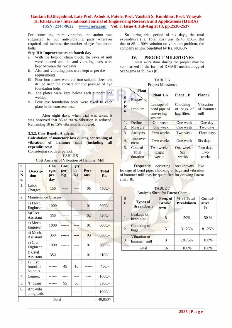
IV. PROJECT MILESTONES Total work done during the project may be
summarized in the form of DMAIC methodology of
Six Sigma as follows [8]:
TABLE 6
Project Milestones
Frequently occurring breakdowns like
leakage of bend pipe, chocking of bags and vibration
of hammer mill may be quantified for drawing Pareto
chart [8].
TABLE 7
Analysis Sheet for Pareto Chart
S
r.
N
o.
Descrip-
tion
Cha
rges
per
day
Cost
per
Kg.
Qty
in
Kg
Pers-
ons Total
Rs.
1. Labor
Charges 150 ----- ---- 05 4500/-
2. Maintenance Charges:
a) Elect.
Engineer 1000 ----- ---- 01 6000/-
b)Elect.
Assistant 350 ------ ---- 02 4200/-
c) Mech.
Engineer 1000 ------ ---- 01 6000/-
d) Mech.
Assistant 350 ------ ---- 03 6300/-
e) Civil
Engineer 1000 ------ ---- 01 6000/-
f) Civil
Assistant 350 ------ ---- 01 2100/-
3. 12”Eye
foundati-
on bolts
on bolt
------ 45 10 ------ 450/-
4. Cement ------ ---- ---- ---- 1000/-
5. „I‟ beam ------ 55 60 3300/-
6. Anti-vibr
ating pads ---- --- ---- ----- 1000/-
Total 40,850/-
S
r.
N
o.
Plant
Phases
Plant 1 A
Plant 1 B
Plant 2
Problem
Leakage of
bend pipe of
conveying
system
Chocking
of bags of
bag filter.
Vibration
of hammer
mill
1. Define One week One week One day
2. Measure One week One week Two days
3. Analysis Two weeks Two week Three days
4. Improve-
ment Two weeks One week Six days
5. Control Two weeks One week Two days
Total
duration
Eight
weeks
Six
weeks
Two
weeks
S
r. Types of
Breakdown
Freq. of
Breakd
own
% of Total
Breakdown
Cumul-
ative
%
1. Leakage of
bend pipe 8 50% 50 %
2. Chocking of
bags 5 31.25% 81.25%
3. Vibration of
hammer mill 3 18.75% 100%
Total 16 100% 100%
Page 7
Gautam B.Ghegadmal, Late.Prof. Ashok S. Patole, Prof. Vaishali S. Kumbhar, Prof. Vinayak
H. Khatawate / International Journal of Engineering Research and Applications (IJERA)
ISSN: 2248-9622 www.ijera.com Vol. 3, Issue 4, Jul-Aug 2013, pp.2530-2537
2536 | P a g e
Fig.11.Pareto chart
V. FINAL COST-BENEFIT ANALYSIS We can summarize profit obtained by two
plants as follows:
TABLE 8
Final Cost- Benefit Analysis
VI. CONCLUSION After completing above said improvements
in automated material handling system of liquor
manufacturing plants, the productivity increased to a
great extent in monitory terms. Workers were
extremely satisfied due to removal of regular
problems viz. leakage of bend pipe, chocking of bags
of bag filter and vibration of hammer mill. There
were intangible benefits like smooth co-ordination
between management and workers, overall employee
satisfaction, external customer requirement
fulfillment, etc. Due to this project, the employee-
employer relationship has also strengthened to a large
extent.
VII. ACKNOWLEDGEMENT Authors are thankful to all the authors and
contributors of the papers which are referred while
preparing this paper.
REFERENCES [1] Mikell P. Groover, Automation, production
systems and computer integrated
manufacturing (Tata McGraw-Hill
Publication Ltd., Third Edition, New Delhi),
781-786.
[2] Eckert, K., Frank, T., Hadlich, T.,Fay, A.,
Vogel-Heuser B., Diedrich, Typical
Automation Functions and Their
Distribution in Automation Systems,
Emerging Technology & Factory
Automation (ETFA) 2011, IEEE 16th
Conference on
10.1109/ETFA.2011.6059123, 1-8.
[3] Sebastian Faltinski, Oliver Niggemann,
Natalia Moriz, and Andre Mankowski,
Automation ML: From Data Exchange to
System Planning and Simulation,
International Conference on Industrial
Technology (ICIT), 2012 IEEE International
Conference on 10. 1109/ICIT.2012.62099,
378-383.
[4] Klotz, T., Straube, B.,Fordham, E., Haufe,
J., Schulze, F., Turek, K., Schmidt, T, An
Approach to the verification of Material
Handling Systems, Emerging Tech-nologies
& Factory Automation (ETFA) 2011,
IEEE16th Conference
10.1109/ETFA..2011.6059043, 1-8.
[5] Masao Ogawa and Yutaka Henmi, Recent
development on PC and PLC based Control
Systems for Beer Brewery Process
Automation Applications, SICE-ICA SE
International Joint Conference 2006, Oct
18- 21, 2006 in Bexco, Bussan, Koria, 1053-
1056.
[6] Schulze, S., Webber, S., Improving
Customer Satisfaction Through Establishing
Strategic Goals for Quality and productivity
Improvement, Global Telecommunications
Conference, Vol.1, 1991, 148-152.
[7] Sivkumar, A., Saravanan, K., Karthikeyan,
C., Suriaprakash Rao, K., Navaneeth
krishnan P, A Simulation Solution for
Improvement of Quality and productivity in
Failure Textile Industry, International
Conference Communication and
S
r.
Problems
faced
Cost before solving
the problem (Rs.)
Benefit after
solving the
problem (Rs.)
1. Leakage of
bend pipe 13,38,800/- 13,38,800/-
2. Choking of
bags 10,48,133/- 10,48,133/-
3. Vibration of
hammer mill 40,850/- 40,850/-
Total 24,27,753/- 24,27,753/-
Page 8
Gautam B.Ghegadmal, Late.Prof. Ashok S. Patole, Prof. Vaishali S. Kumbhar, Prof. Vinayak
H. Khatawate / International Journal of Engineering Research and Applications (IJERA)
ISSN: 2248-9622 www.ijera.com Vol. 3, Issue 4, Jul-Aug 2013, pp.2530-2537
2537 | P a g e
Computational Intelligence (INC OCCI)
on IEEE Conference publications 2010,
17-21.
[8] M.S. Mahajan, Statistical quality control
(Dhanpat Rai and Co (P) Ltd.,Third
Revised Edition, New Delhi), 426-428,
469-472.
[9] Hamadallah Mohammad Al-Baijat, The
Use of Basalt Aggregates in Concrete
Mixes in Jordan, Jordan Jounal of Civil
Engineering, Volume 2, No.1, 2008, 63-
70.
[10] N.S.V. Kameswara Rao, Mechanical
vibrations of elastic systems (Asian Books
Private Limited, First Edition, New
Delhi), 29-32.
[11] Bon, A. T., Lim ping ping,
Implementation of Total Productive
Maintenance (TPM) in Automotive
Industry, Business, Engineering and
Industrial Applications (ISBEIA) 2011,
IEEE symposium on 10.
1109/ISBE.2011.6088881,55-58.
[12] P. Radhakrishanan, S. Subramanian, V.
Raju, CAD/CAM/CIM (New age
international Publisher, Second Edition,
New Delhi, 81-224-1248-3), 329-339
Fig. 12. Automated material handling system of liquor manufacturing plant (Using Pneumatic Conveying
System)