45
TRANSPORT Jean-Paul Moskowitz 13/04/2010 Onboard Energy Storage: The experience of a Tramway Manufacturer
TRANSPORT
Jean-Paul Moskowitz13/04/2010
Onboard Energy Storage: The experience of a Tramway Manufacturer
IET RTS 2010 ; 13 - 15 April 2010, Birmingham, UK - P 2
Agenda
Market requirements – Energy needs Page 2
Energy Storage technologies : Flywheel Page 14
Energy Storage technologies : NiMH Batteries Page 23
Energy Storage technologies : Supercapacitors: STEEM project Page 28
IET RTS 2010 ; 13 - 15 April 2010, Birmingham, UK - P 3
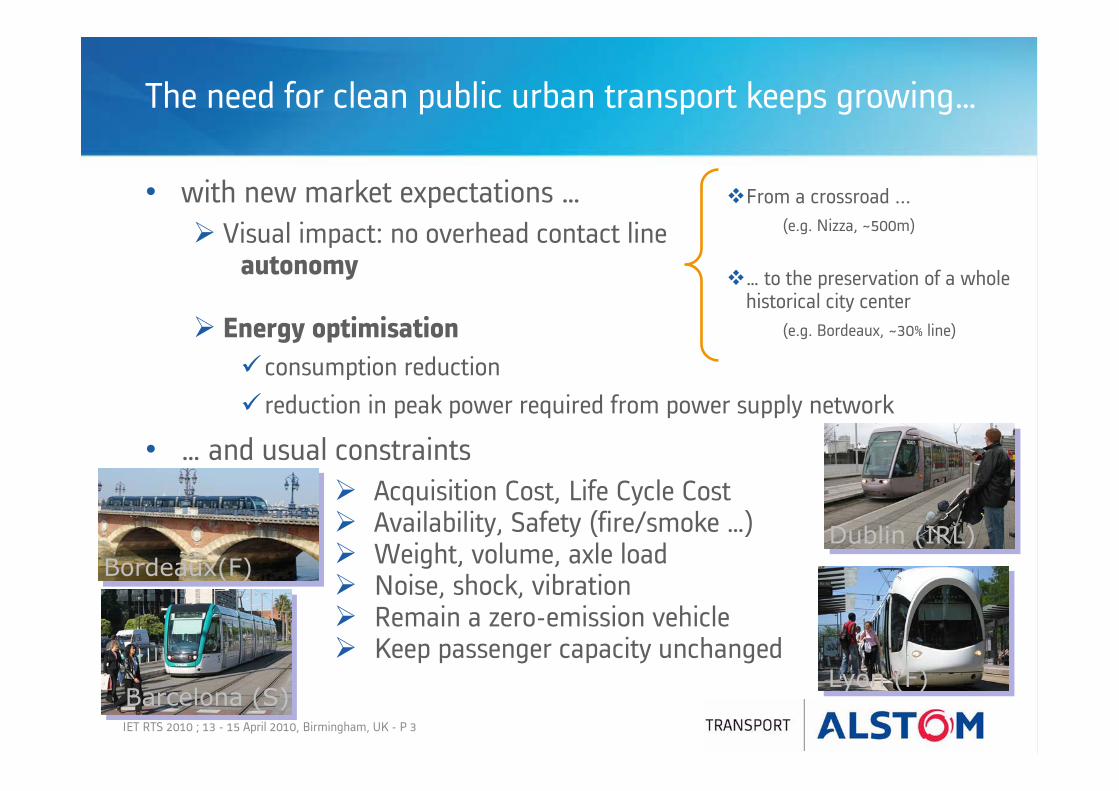
The need for clean public urban transport keeps growing…
• with new market expectations …Visual impact: no overhead contact line
autonomy
Energy optimisationconsumption reductionreduction in peak power required from power supply network
From a crossroad ...(e.g. Nizza, ~500m)
… to the preservation of a whole historical city center
(e.g. Bordeaux, ~30% line)
Dublin (IRL)
Barcelona (S)Lyon (F)
Bordeaux(F)
• … and usual constraintsAcquisition Cost, Life Cycle CostAvailability, Safety (fire/smoke …)Weight, volume, axle loadNoise, shock, vibrationRemain a zero-emission vehicleKeep passenger capacity unchanged

IET RTS 2010 ; 13 - 15 April 2010, Birmingham, UK - P 4
Erasing the OverHead Contact Line:makes tramway integration into the city easier

IET RTS 2010 ; 13 - 15 April 2010, Birmingham, UK - P 5
Erasing the OverHead Contact Line:makes tramway integration into the city easier

IET RTS 2010 ; 13 - 15 April 2010, Birmingham, UK - P 6
Erasing the OverHead Contact Line:makes tramway integration into the city easier
Copyright: CANCA/Eric Boizet

IET RTS 2010 ; 13 - 15 April 2010, Birmingham, UK - P 7
Typical tramway operator’s requirementsover a catenaryless section
• Nominal trip: Speed >= 30 km/h with no unscheduled stop
• Heavy traffic: Reduced speed, twice the nominal time
• Tramway stopped:Possibility to have one, two or three non scheduled stops between regular passenger exchange stations
• Failed train: Allow push-pull operation by another train

IET RTS 2010 ; 13 - 15 April 2010, Birmingham, UK - P 8
Braking energy recovery
Sub-station Traction Braking
Electric Sub-station
Recovery Grid restitution
Rheostatic losses
Braking energy recovery WITHOUTOnboard Energy Storage System (ESS)

IET RTS 2010 ; 13 - 15 April 2010, Birmingham, UK - P 9
Braking energy recovery
TractionTraction Braking
Electric Sub-station
Recovery Grid restitution
Rheostatic lossesESS discharge ESS recharge
Sub-station
Braking energy recovery WITHOnboard Energy Storage System (ESS)

IET RTS 2010 ; 13 - 15 April 2010, Birmingham, UK - P 10
Erasing the OverHead Contact Line
Partial Autonomy (~400m) withOnboard Energy Storage System (ESS)
ESS Recharge from Substation whileStopped in passengerstation
ESS discharge Traction Energy Refill
ESS RechargeRheostatic losses
Braking Energy

IET RTS 2010 ; 13 - 15 April 2010, Birmingham, UK - P 11
Typical tramway figures
Some vehicle orders of magnitude
weight:
Mean consumption: Peak power:Mean power:
inc. auxiliaries: Life time:
Some tramway line characteristics
Average distance between stations: 400 mYearly tram mileage: 60 000 kmMean stop time in station: 20 s
50 t (empty) to 80 t (6 passagers/m²)6-7 kWh/km1000 to 1300 kW100 to 180 kW
15 to 80 kW30 years
Vehicle length 40 m
40 t (empty) to 60 t (6 passagers/m²)4-5 kWh/km650 to 900 kW80 to 150 kW
15 to 60 kW30 years
30 m

IET RTS 2010 ; 13 - 15 April 2010, Birmingham, UK - P 12
Energy consumption (40m tram)
AW0 / Paux=18kWEnergie CdT + Aux (kWh)
= f(Vmax, pente)
0
1
2
3
4
5
6
7
0 100 200 300 400 500 600 700d (m)
E (k
Wh)
0% - 30km/h0% - 20 km/h2% - 30 km/h2% - 20km/h4% - 30km/h
AW0 / Paux=45kWEnergie CdT + Aux (kWh)
= f(Vmax, pente)
0
1
2
3
4
5
6
7
0 100 200 300 400 500 600 700d (m)E
(kW
h)
0% - 30km/h0% - 20 km/h2% - 30 km/h2% - 20km/h4% - 30km/h
Influence of auxiliaries

IET RTS 2010 ; 13 - 15 April 2010, Birmingham, UK - P 13
Energy consumption (40m tram)
Influence of passenger loadAW0 / Paux=45kW
Energie CdT + Aux (kWh)= f(Vmax, pente)
0
1
2
3
4
5
6
7
0 100 200 300 400 500 600 700d (m)
E (k
Wh)
0% - 30km/h0% - 20 km/h2% - 30 km/h2% - 20km/h4% - 30km/h
AW2 / Paux=45kWEnergie CdT + Aux (kWh)
= f(Vmax, pente)
0
1
2
3
4
5
6
7
8
9
0 100 200 300 400 500 600 700d (m)
E (k
Wh)
0% - 30km/h0% - 20 km/h2% - 30 km/h2% - 20km/h4% - 30km/h
AW3 / Paux=45kWEnergie CdT + Aux (kWh)
= f(Vmax, pente)
0
1
2
3
4
5
6
7
8
9
10
0 100 200 300 400 500 600 700d (m)
E (k
Wh)
0% - 30km/h0% - 20 km/h2% - 30 km/h2% - 20km/h4% - 30km/h
AW2 : 4 pax / m²
AW3 : 6 pax. / m²
AW0 : Empty
IET RTS 2010 ; 13 - 15 April 2010, Birmingham, UK - P 14
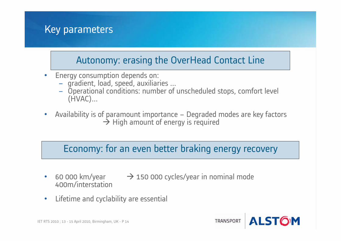
Economy: for an even better braking energy recovery
Autonomy: erasing the OverHead Contact Line
Key parameters
• Energy consumption depends on:gradient, load, speed, auxiliaries ...Operational conditions: number of unscheduled stops, comfort level(HVAC)...
• Availability is of paramount importance – Degraded modes are key factors High amount of energy is required
• 60 000 km/year 150 000 cycles/year in nominal mode 400m/interstation
• Lifetime and cyclability are essential

IET RTS 2010 ; 13 - 15 April 2010, Birmingham, UK - P 15
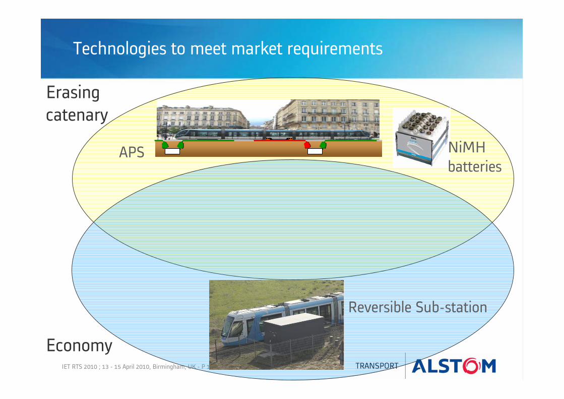
Erasingcatenary
NiMHbatteries
APS
Technologies to meet market requirements
IET RTS 2010 ; 13 - 15 April 2010, Birmingham, UK - P 16
Erasingcatenary
NiMHbatteries
APS
Technologies to meet market requirements
Economy
Reversible Sub-station

IET RTS 2010 ; 13 - 15 April 2010, Birmingham, UK - P 17
Erasingcatenary
NiMHbatteries
APS
Technologies to meet market requirements
Economy
Reversible Sub-station
supercapacitors
IET RTS 2010 ; 13 - 15 April 2010, Birmingham, UK - P 18
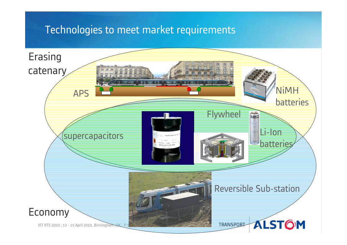
Erasingcatenary
NiMHbatteries
APS
Technologies to meet market requirements
Economy
Reversible Sub-station
supercapacitors
Flywheel
Li-Ionbatteries
IET RTS 2010 ; 13 - 15 April 2010, Birmingham, UK - P 19
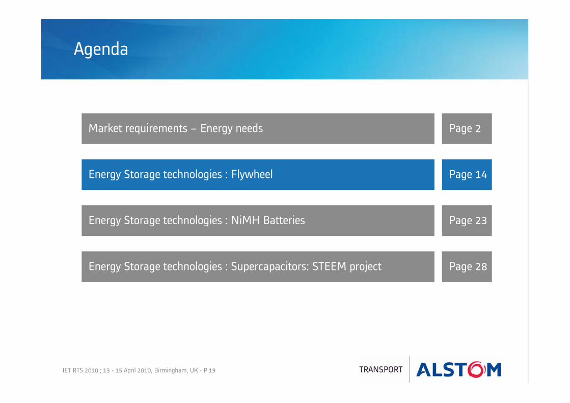
Agenda
Market requirements – Energy needs Page 2
Energy Storage technologies : Flywheel Page 14
Energy Storage technologies : NiMH Batteries Page 23
Energy Storage technologies : Supercapacitors: STEEM project Page 28
IET RTS 2010 ; 13 - 15 April 2010, Birmingham, UK - P 20
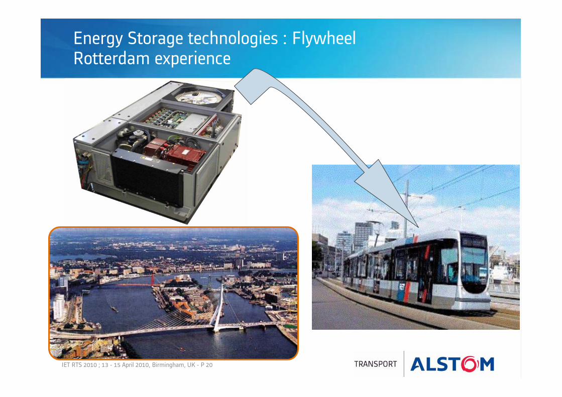
Energy Storage technologies : FlywheelRotterdam experience

IET RTS 2010 ; 13 - 15 April 2010, Birmingham, UK - P 21
Schematic view of Flywheel Motor/Generator Unit
Function of the electronicpower converter
Energy Storage technologies: Flywheel
Storage of electric power : conversion to kinetic energy
rotor
Bearing unitStator
Cooling unit
Containment unit
Magnetic unit
IET RTS 2010 ; 13 - 15 April 2010, Birmingham, UK - P 22
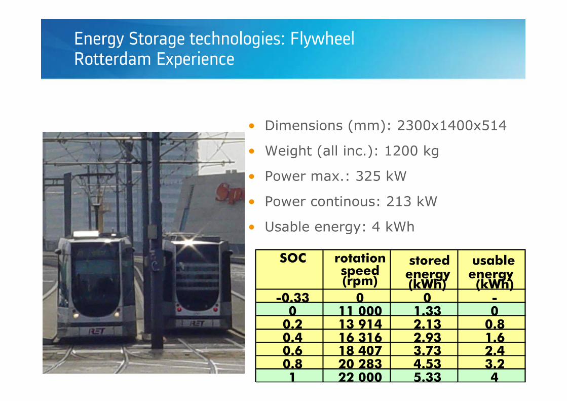
• Dimensions (mm): 2300x1400x514
• Weight (all inc.): 1200 kg
• Power max.: 325 kW
• Power continous: 213 kW
• Usable energy: 4 kWh
SOC rotation speed(rpm) energy
stored
(kWh)energyusable
(kWh)-0.33 0 0 -
0 11 000 1.33 00.2 13 914 2.13 0.80.4 16 316 2.93 1.60.6 18 407 3.73 2.40.8 20 283 4.53 3.21 22 000 5.33 4
Energy Storage technologies: FlywheelRotterdam Experience

IET RTS 2010 ; 13 - 15 April 2010, Birmingham, UK - P 23
Energy Storage technologies: FlywheelRotterdam Experience
Performances for autonomy
• AW0 max: 2 km - 50 km/h
• AW3 max: 1.5 km - 45 km/h (without heating)
• Mean interstation in AW3: 500 m – 45 km/h - 0,45 m/s²(see figures)

IET RTS 2010 ; 13 - 15 April 2010, Birmingham, UK - P 24
Energy Storage technologies: FlywheelRotterdam Experience
Performances under catenary (1/3) : peak shaving
Idc FW (A)Ipanto (A)
Without Flywheel : I panto max = 1000A
With Flywheel : I panto max = 700A

IET RTS 2010 ; 13 - 15 April 2010, Birmingham, UK - P 25
Energy Storage technologies: FlywheelRotterdam Experience
Performances under catenary (2/3) : smoothing catenary voltage
Without Flywheel With Flywheel
Rotterdam nominal voltage is 600V (not 750 V)

IET RTS 2010 ; 13 - 15 April 2010, Birmingham, UK - P 26
Energy Storage technologies: FlywheelRotterdam Experience
Performances under catenary (3/3): braking energy recovery
Without Flywheel: Prheo = 300 kW
With Flywheel: Prheo = 0 kW
Pdc FW (kW)Ppanto (kW)Prheo (kW)

IET RTS 2010 ; 13 - 15 April 2010, Birmingham, UK - P 27
Energy Storage technologies: Flywheel
Good balance Energy/Power
Actual equipments are prototypes which have not yet reached industrial maturity:
• Weight/volume optimisation• Industrialisation process• Improved reliability and safety
Ongoing R&D project, with the support of ANR, aims at developing the product suiting railways constraints.
IET RTS 2010 ; 13 - 15 April 2010, Birmingham, UK - P 28
Agenda
Market requirements – Energy needs Page 2
Energy Storage technologies : Flywheel Page 14
Energy Storage technologies : NiMH Batteries Page 23
Energy Storage technologies : Supercapacitors: STEEM project Page 28

IET RTS 2010 ; 13 - 15 April 2010, Birmingham, UK - P 29
Energy Storage technologies: NiMH batteries Partial Autonomy in Nice (F)
Batteries NiMH SAFT: NHP 10-340 68 modules - 12V eachOperating temperature : 25 °C - cooling: glycoled waterMax power (end of life): 200 kWUseful capacity: 34 Ah
Battery box
Switchgear box
ChargerBTMS (Battery Thermal Management System)

IET RTS 2010 ; 13 - 15 April 2010, Birmingham, UK - P 30
Energy Storage technologies: NiMH batteries Partial Autonomy in Nice (F)
Battery box
Charger box
Switchgear box
IET RTS 2010 ; 13 - 15 April 2010, Birmingham, UK - P 31
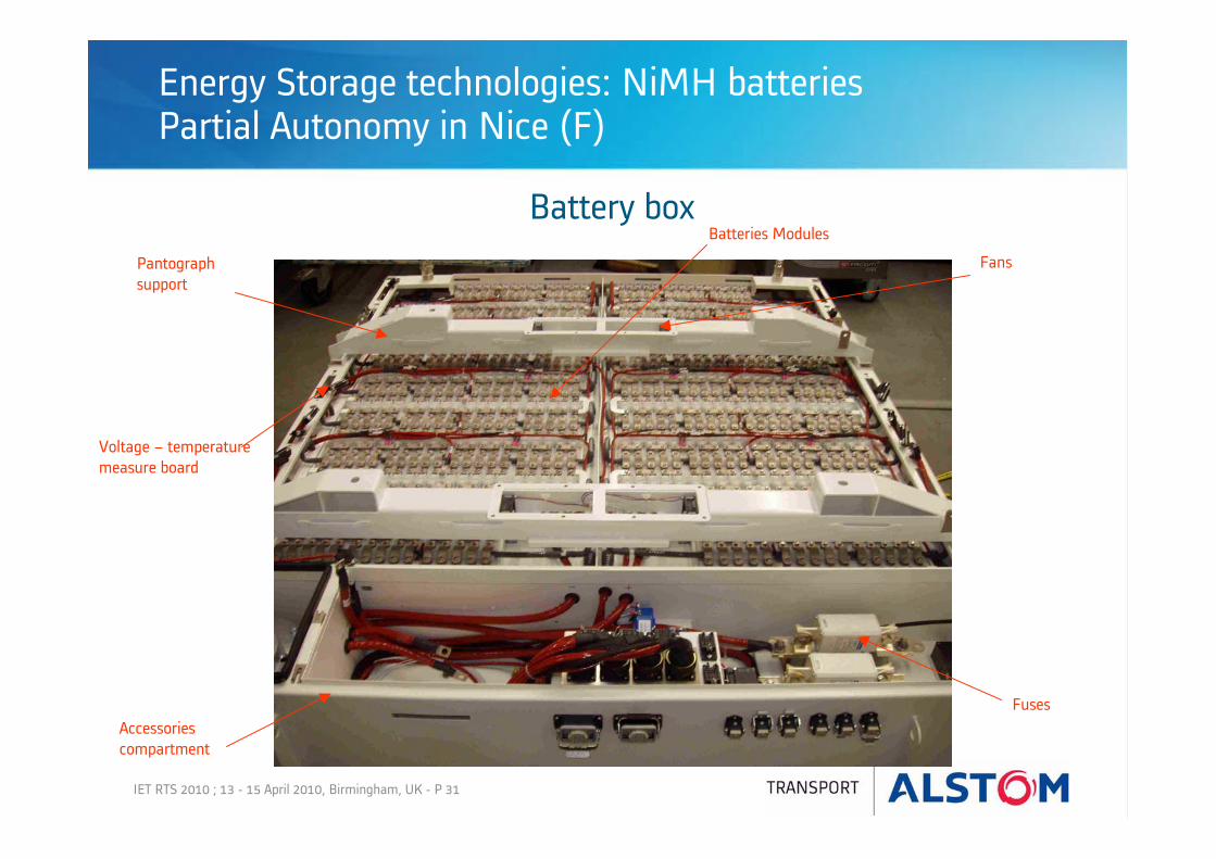
Energy Storage technologies: NiMH batteries Partial Autonomy in Nice (F)
Battery boxPantographsupport
Voltage – temperature measure board
Fans
Batteries Modules
Accessoriescompartment
Fuses

IET RTS 2010 ; 13 - 15 April 2010, Birmingham, UK - P 32
Energy Storage technologies: NiMH batteries Partial Autonomy in Nice (F)
• Revenue service in november 2007
• 8,7 km, 21 stations, 20 Citadis 302 trams
• No overhead wires on places Masséna (435 m) and Garibaldi (485 m)
• Battery contractual lifetime: 5 years, i.e. 35 000 cycles
Comte de Falicon
Jean MédecinMasséna
Jean Jaurès
Garribaldi
Pont Michel
4100 m
3200 m
435 m
485 m332 m
Nice Line 1
CENTRE DE MAINTENANCE

IET RTS 2010 ; 13 - 15 April 2010, Birmingham, UK - P 33
Agenda
Market requirements – Energy needs Page 2
Energy Storage technologies : Flywheel Page 14
Energy Storage technologies : NiMH Batteries Page 23
Energy Storage technologies : Supercapacitors: STEEM project Page 28

IET RTS 2010 ; 13 - 15 April 2010, Birmingham, UK - P 34
R&D project between Alstom Transport, RATP and INRETS, with the support of ADEME underPREDIT national funding program
: Operate between 2 stations with pantograph loweredEvaluate energy savingsTest quick recharge in depotAcquire REX on supercapacitors, their behaviourAcquire REX on the operation of a tram with supercapacitors
Energy Storage technologies: SupercapacitorsSTEEM project (ALSTOM – RATP – supported by ADEME)
Experience objectives
RATP T3: 7.9 km17 stations21 Citadis 402(18 during peak hours)

IET RTS 2010 ; 13 - 15 April 2010, Birmingham, UK - P 35
STEEM : Energy consumption simulations for T3 line
IET RTS 2010 ; 13 - 15 April 2010, Birmingham, UK - P 36
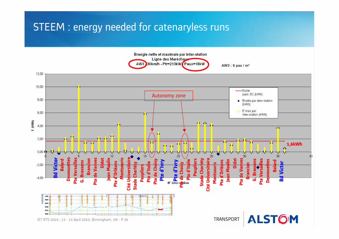
STEEM : energy needed for catenaryless runs
Bd V
icto
rBa
lard
Desn
ouet
tes
Pte
Vers
aille
sG.
Bra
ssen
sBr
anci
onPt
e de
Van
ves
Dido
tJe
an M
oulin
Pte
d’Or
léan
sM
onts
ouris
Cité
Uni
vers
itaire
Stad
e Ch
arlé
tyPe
uplie
rsPt
e d’
Ital
iePt
e de
Cho
isy
Pte
d’Iv
ry
Bd V
icto
rBa
lard
Desn
ouet
tes
Pte
Vers
aille
sG.
Bra
ssen
sBr
anci
onPt
e de
Van
ves
Dido
tJe
an M
oulin
Pte
d’Or
léan
sM
onts
ouris
Cité
Uni
vers
itaire
Stad
e Ch
arlé
tyPe
uplie
rsPt
e d’
Ital
iePt
e de
Cho
isy
Autonomy zone
AW3 : 6 pax / m²
1,6kWh
Pte
d’Iv
ry

IET RTS 2010 ; 13 - 15 April 2010, Birmingham, UK - P 37
W utile = 1,62 KWhP soc 0 = 350 KWP soc 1 = 500 KW
Msc=720 kg
Recharge time < 20 s
STEEM : Use of Batscap modules
Cell: 2600F 1 module = 20 cells connected in series
STEEM supercaps box:48 modules, 6 branches in parallel, each with 8 modules in series
U = 2,5 V
U = 50 V
U = 400 V
IET RTS 2010 ; 13 - 15 April 2010, Birmingham, UK - P 38
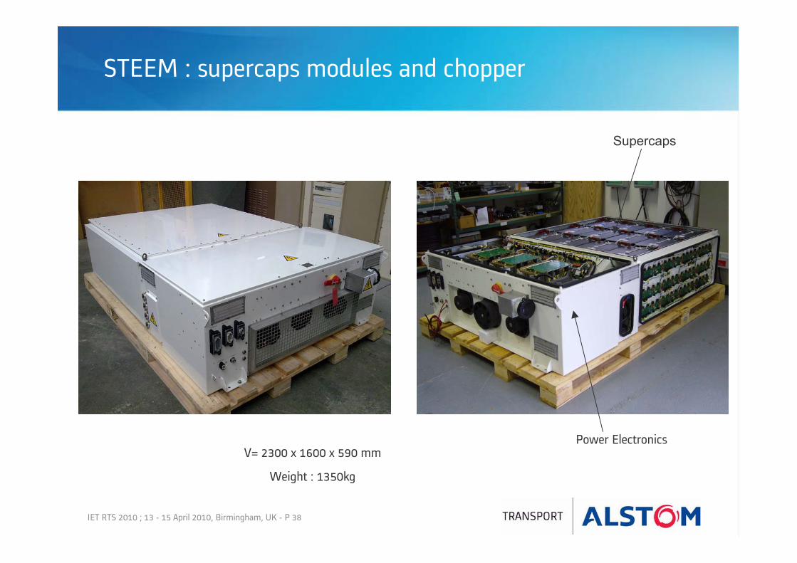
STEEM : supercaps modules and chopper
Supercaps
Power ElectronicsV= 2300 x 1600 x 590 mm
Weight : 1350kg

IET RTS 2010 ; 13 - 15 April 2010, Birmingham, UK - P 39
STEEM:Installation of supercapacitors on roof of RATP Citadis
ESS box: supercaps and chopper
IET RTS 2010 ; 13 - 15 April 2010, Birmingham, UK - P 40
Défauts
Tests MaintenanceExploitationEtat
du tram
M1 M2
NN
MODEM1 M2
SS
FREINS
SNP
SNM
NNM
12 14 1611 13 15
21322231
23252426
750 V
Présence tensions
24 V 400 V Retourécran ICS
Divers
Etdu
5%
750 V
Disjoncteur principal
Disjoncteur SATEE
30Km/h
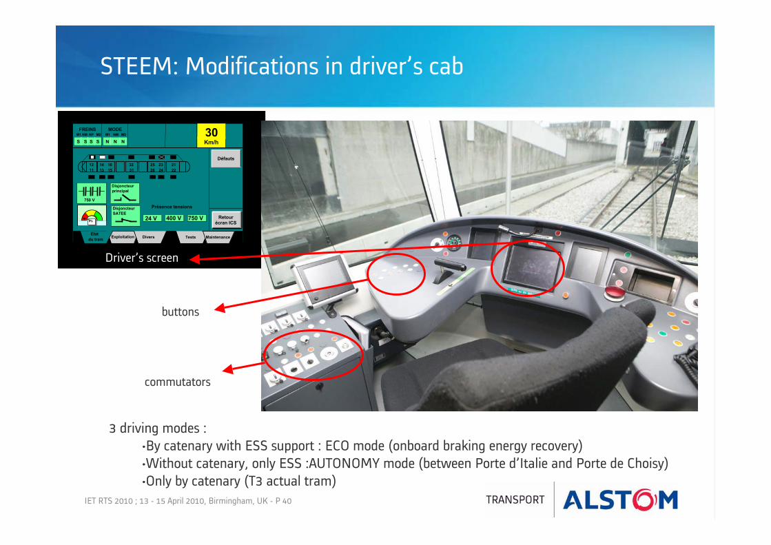
STEEM: Modifications in driver’s cab
commutators
buttons
Driver’s screen
3 driving modes :•By catenary with ESS support : ECO mode (onboard braking energy recovery)•Without catenary, only ESS :AUTONOMY mode (between Porte d’Italie and Porte de Choisy)•Only by catenary (T3 actual tram)

IET RTS 2010 ; 13 - 15 April 2010, Birmingham, UK - P 41
STEEM: Operation in revenue service – end of March
15 761 km with 998 round trips

IET RTS 2010 ; 13 - 15 April 2010, Birmingham, UK - P 42
STEEM – performances in autonomy
• Porte d’Italie-Porte de Choisy (300m) : tested at night in AW3 (6 passengers/m²)
• With passengers in revenue service
• In manual mode or automatic mode (detection by GPS)

IET RTS 2010 ; 13 - 15 April 2010, Birmingham, UK - P 43
STEEM – performances in Ecomode : up to 30%
Braking energy stored in supercaps is reused for acceleration and auxiliaries during next traction phase
Comparison with another tram in operation at the same time
These preliminaries result must be watched over a long period of time to avoid bias
Comparison of energy consumption
0
50
100
150
200
250
300
14:55:00 16:07:00 17:19:00 18:31:00 19:43:00
Time
Ener
gy (k
Wh)
STEEM tram Classic tram
Influencing parameters
peak/off-peak hours
auxiliaries consumption (HVAC, depending on temperature)
driving

IET RTS 2010 ; 13 - 15 April 2010, Birmingham, UK - P 44
Advantages of onboard energy storage
• Supercapacitors allow both autonomy and economy modes
• OverHead Contact Line removal on some parts of the line, for aesthetic reasons, construction requests, depending on operational conditions
• Energy savings up to 30%
• CO2 reduction
• Reduction of peak power demand
• Smoothing of supply voltage
• Safe operation (STEEM certification by Certifer)

www.alstom.com


