Onboard Perception-Based Trotting and Crawling with the Hydraulic Quadruped Robot (HyQ) Ioannis Havoutis Jesus Ortiz St´ ephane Bazeille Victor Barasuol Claudio Semini Darwin G. Caldwell Abstract— This paper presents a framework developed to increase the autonomy and versatility of a large (∼75kg) hydraulically actuated quadrupedal robot. It combines on- board perception with two locomotion strategies, a dynamic trot and a static crawl gait. This way the robot can perceive its environment and arbitrate between the two behaviours accord- ing to the situation at hand. All computations are performed on-board and are carried out in two separate computers, one handles the high-level processes while the other is concerned with the low-level hard real-time control. The perception and subsequently the appropriate gait modifications are performed autonomously. We present outdoor experimental trials of the robot trotting over unknown terrain, perceiving a large obstacle, altering its behaviour to the cautious crawl gait and stepping onto the obstacle. This allows the robot to locomote quickly on relatively flat terrain and gives the robot the ability to overcome large irregular obstacles when required. I. I NTRODUCTION Legged robots are naturally superior at accessing a large variety of surface conditions than wheeled robots. This is partially due to the ability of legged systems (bipeds, quadrupeds, etc.) to decouple the path of the robot from the sequence of footholds and due to their inherent ability to utilize a range of locomotion strategies, tailored to the situation at hand. This way a legged robot –or animal– can chose a dynamic locomotion strategy, e.g. trot, gallop, when faced with terrain where accurate foot placement is not crucial for the success of the behavior. These can be situations where the robot locomotes on surfaces of varying conditions, e.g. grass, soil, pebbles, gravel, and varying inclination, where the support surface can be regarded as continuous. On the other hand, on structured environments or terrain with discrete footholds, e.g. steps, stairs, cluttered rooms, legged robots can employ a range of –typically non- gaited– static or quasi-static locomotion strategies that rely more on accurate foothold planning, and consequentially on the features of the terrain. In the dynamic locomotion case, quadruped robots have been shown to successfully operate with minimal exterocep- tive feedback [1], [2], [3], [4]. In most cases an on-board inertial measurement unit (IMU) is used to feedback the systems’ attitude, while such input is adequate to overcome I. Havoutis, J. Ortiz, S. Bazeille, C. Semini and Darwin G. Caldwell are with the Department of Advanced Robotics, Istituto Italiano di Tecnologia, 16163 Genova, Italy. email: {ioannis.havoutis, jesus.ortiz, stephane.bazeille, claudio.semini, darwin.caldwell}@iit.it V. Barasuol is with the Department of Automation and Systems, Federal University of Santa Catarina (UFSC), Florianpolis, SC, Brazi. email: [email protected]. (a) Robot on step. (b) Robot model and depth data. Fig. 1. (a) The HyQ quadruped robot stepping onto a wooden block that is 15cm tall. (b) The HyQ model within the ROS framework. This is used on-line in the perception layer to calculate transformations between the defined reference frames. The red rectangle in front of the quadruped’s body represents the depth sensor and its coordinate frame. Note that the two snapshots do not correspond to the same time instant or trial. stochastic disturbances and deduce the surface inclination. In contrast non-gaited locomotion approaches rely more on exteroceptive feedback as higher order, cognitive, processes are critical to the success of the behavior. This, usually more computationally intensive, feedback comes from perception sensors, visual or depth, that are used to ‘make sense’ of the robot’s environment and are subsequently used –primarily– for foothold selection, map-building and localization, colli- sion detection and avoidance, and navigation. Our main contribution in this paper is a control frame- work that can leverage the full set of benefits of legged locomotion, by combining a dynamic trotting behavior and a planning-based crawl-gait locomotion strategy. This allows our quadruped robot –HyQ– to autonomously and dynam- ically traverse continuous terrain of varying roughness and statically locomote over discontinuous, challenging unknown terrain. Such terrain includes big or irregular obstacles and environments where careful foot placement is crucial. In addition we wish to underline that all perception is performed on-board, i.e. no external motion capture system is used to localize the robot or portions of the environment, while also no a priory map of the environment is used. To our knowledge this is the first time that a large-scale quadruped robot combines these two types of locomotion strategies, dynamic trotting and planning based crawl-gait, without any external localization or map information.
Transcript
Onboard Perception-Based Trotting and Crawlingwith the Hydraulic Quadruped Robot (HyQ)
Ioannis Havoutis Jesus Ortiz Stephane Bazeille Victor Barasuol Claudio Semini Darwin G. Caldwell
Abstract— This paper presents a framework developed toincrease the autonomy and versatility of a large (∼75kg)hydraulically actuated quadrupedal robot. It combines on-board perception with two locomotion strategies, a dynamictrot and a static crawl gait. This way the robot can perceive itsenvironment and arbitrate between the two behaviours accord-ing to the situation at hand. All computations are performedon-board and are carried out in two separate computers, onehandles the high-level processes while the other is concernedwith the low-level hard real-time control. The perception andsubsequently the appropriate gait modifications are performedautonomously. We present outdoor experimental trials of therobot trotting over unknown terrain, perceiving a large obstacle,altering its behaviour to the cautious crawl gait and steppingonto the obstacle. This allows the robot to locomote quickly onrelatively flat terrain and gives the robot the ability to overcomelarge irregular obstacles when required.
I. INTRODUCTION
Legged robots are naturally superior at accessing a largevariety of surface conditions than wheeled robots. Thisis partially due to the ability of legged systems (bipeds,quadrupeds, etc.) to decouple the path of the robot fromthe sequence of footholds and due to their inherent abilityto utilize a range of locomotion strategies, tailored to thesituation at hand. This way a legged robot –or animal–can chose a dynamic locomotion strategy, e.g. trot, gallop,when faced with terrain where accurate foot placement isnot crucial for the success of the behavior. These can besituations where the robot locomotes on surfaces of varyingconditions, e.g. grass, soil, pebbles, gravel, and varyinginclination, where the support surface can be regarded ascontinuous. On the other hand, on structured environmentsor terrain with discrete footholds, e.g. steps, stairs, clutteredrooms, legged robots can employ a range of –typically non-gaited– static or quasi-static locomotion strategies that relymore on accurate foothold planning, and consequentially onthe features of the terrain.
In the dynamic locomotion case, quadruped robots havebeen shown to successfully operate with minimal exterocep-tive feedback [1], [2], [3], [4]. In most cases an on-boardinertial measurement unit (IMU) is used to feedback thesystems’ attitude, while such input is adequate to overcome
I. Havoutis, J. Ortiz, S. Bazeille, C. Semini and Darwin G. Caldwell arewith the Department of Advanced Robotics, Istituto Italiano di Tecnologia,16163 Genova, Italy. email: {ioannis.havoutis, jesus.ortiz, stephane.bazeille,claudio.semini, darwin.caldwell}@iit.it V. Barasuol is with the Departmentof Automation and Systems, Federal University of Santa Catarina (UFSC),Florianpolis, SC, Brazi. email: [email protected].
(a) Robot on step. (b) Robot model and depth data.
Fig. 1. (a) The HyQ quadruped robot stepping onto a wooden blockthat is 15cm tall. (b) The HyQ model within the ROS framework. This isused on-line in the perception layer to calculate transformations betweenthe defined reference frames. The red rectangle in front of the quadruped’sbody represents the depth sensor and its coordinate frame. Note that thetwo snapshots do not correspond to the same time instant or trial.
stochastic disturbances and deduce the surface inclination.In contrast non-gaited locomotion approaches rely more onexteroceptive feedback as higher order, cognitive, processesare critical to the success of the behavior. This, usually morecomputationally intensive, feedback comes from perceptionsensors, visual or depth, that are used to ‘make sense’ of therobot’s environment and are subsequently used –primarily–for foothold selection, map-building and localization, colli-sion detection and avoidance, and navigation.
Our main contribution in this paper is a control frame-work that can leverage the full set of benefits of leggedlocomotion, by combining a dynamic trotting behavior anda planning-based crawl-gait locomotion strategy. This allowsour quadruped robot –HyQ– to autonomously and dynam-ically traverse continuous terrain of varying roughness andstatically locomote over discontinuous, challenging unknownterrain. Such terrain includes big or irregular obstacles andenvironments where careful foot placement is crucial. Inaddition we wish to underline that all perception is performedon-board, i.e. no external motion capture system is usedto localize the robot or portions of the environment, whilealso no a priory map of the environment is used. To ourknowledge this is the first time that a large-scale quadrupedrobot combines these two types of locomotion strategies,dynamic trotting and planning based crawl-gait, without anyexternal localization or map information.
II. HYQ ROBOT OVERVIEW
All work presented in this paper was carried out us-ing a hydraulic quadruped robot, the HyQ. HyQ weightsapproximately 75kg, is 1m long, 0.5m wide and 1m tallwhen its legs are fully stretched. It is designed and builtin-house and has 12 degrees of freedom, 4 of which areelectrically actuated (hip adduction/abduction joints) whilethe rest are hydraulically driven [5]. In addition it has anon-board inertial measurement unit (IMU) and recently anRGBD color and depth sensor (Microsoft Kinect) has beenintegrated (Fig. 1).
HyQ is equipped with two on-board computers that com-municate via Ethernet. There is a pc-104 that runs real-timepatched Linux (Xenomai) and is responsible for the low-level hard-real-time control of the robot actuators. Also real-time critical parts of the controllers run on this machine. Thesecond is a stronger pc (Intel i7, 16gb) that runs Linux aswell as the open source Robot Operating System (ROS) [6].It is dedicated to high level processes as state estimation,localization and mapping and foothold computation. ROS isresponsible for reading and publishing data from the per-ception sensors. All the generally computationally intensiveperception procedures are built as ROS nodes while the jointstate and attitude of the robot is published by the real-timepc.
III. RELATED WORK
The work of Raibert [4] has been influential to research ondynamic locomotion approaches. Most of this was concernedwith small to medium sized systems utilizing hydraulic andpneumatic actuators, and springs. Intuitive control laws wereused for trotting while considerable gain tuning was required.Recently Rutishauser et al. [7] explored passive compli-ance approaches, where a lightweight passive spring-loadedquadrupedal structure with minimal actuation (1 motor perleg) was used. Remy et al. in [8] explored passively stabledynamic locomotion approaches over a range of differentgaits, using a medium sized spring loaded model with a sim-plified telescopic leg. Ugurlu et al. in [9] experimented withtrotting on a stiff electrically actuated quadruped robot wherean active compliance control framework was used. BostonDynamics’ Big Dog and LS3 are two of the most impressivequadrupedal platforms. Their remarkable performance hasbeen demonstrated, mostly though videos online. However,no details on the hardware design or control methods havebeen published to date, therefore making the comparisonagainst other approaches difficult.
A large body of literature in deliberate planning ap-proaches in quadrupedal locomotion has resulted from theDARPA-funded learning locomotion challenge. The teamsinvolved in this competition produced similar planning andcontrol solutions [10], [11], [12]. All teams built upon aglobal plan over sets of given maps, while footholds wereselected with hand-tuned, and learnt, features of varyingterrain area resolution. The difference from our case is that inall this work a precise model of the environment was givento the planning and control framework, while an accurate
ComputeRelative Displacement
Poin
t Clo
ud (R
GB,
XY
Z) /
IMU
Extract dominant plane
Generate ground texture
Compute gradients
FFT
Match
Inverse FFT
Modulus
Get best match
Extract ground height-map
Complexgroundtex freq
(current)
Complexgroundtex freq
(previous)
XYZ
XYZ, RGB
XYZ
Height-map
Calculate rotation matrix
Calculate homography
Yaw
Update height-map(X,Y)
Fig. 2. Map builder pipeline. From the vision information (point cloud)and the sensory information (IMU), this algorithm extracts the pose of thecamera with respect to the ground, and the relative transformation betweentwo consecutive frames. Each item in the text corresponds to a block in thefigure.
motion capture setup provided the complete state of therobot.
Kolter et al. in [13] took a step further in autonomy byremoving the dependence on given maps and external stateinput. In their control framework they use a well establishedpoint-cloud matching technique to iteratively build a map oftheir environment and afterwards navigate in it.
A lot of work in robotics focuses on the problem ofsimultaneous localization an mapping (SLAM). A recentexample that is popular with ROS and the Kinect RGBDsensor is [14]. This has been used to generate maps thatcan be stored offline and used to localize in an onlinemanner [15]. Using such approaches in real-time is an openproblem as such solutions are generally computationallymore demanding while they often operate in a time-scale thatis inappropriate for a fast-paced legged robot. In previouswork [16] we used single frame information from a stereocamera to track visual targets or modulate parameters of atrotting gait.
IV. PERCEPTION AND MAP GENERATION
In this work, we made the assumption that walking takesplace on a mostly flat and horizontal surface and we designedan algorithm that can work in these conditions in real-time.We plan to improve the current pipeline by incorporatingthe Iterative Closest Point (ICP) algorithm for terrains thatdo not have a dominant plane.
The map generation relies also in other sensory informa-tion, such as the IMU. In practical terms, we are using onlythe yaw information. The map building pipeline as shown inFig. 2, and the related computations are done as follows: 1)Acquire the sensory information including the point cloudwith color information (XYZ/RGB) and the trunk yaw fromthe IMU. 2) Extract the dominant plane from the pointcloud. This is done using the standard RANSAC algorithmon XYZ values. The plane extraction gives us the height
of the camera (Z). 3) Calculate the rotation matrix. Usingthe normal of the dominant plane previously calculated, andthe yaw information coming from the IMU. 4) Calculatethe transformation between the ground space and the cameraspace (homography), using four pairs of points from the pointcloud laying on the dominant plane. 5) Project theRGB pointsfrom the point cloud into the ground surface and generate theground texture. This texture includes only intensity and notcolor information, in single precision floating point format.Only the points laying on the dominant plane are projectedonto this texture. The empty spaces are filled with −1.0. 6)Compute the relative displacement between two consecutiveframes (X, Y). Instead of performing a direct comparisonbetween the ground texture, we do a matching in the fre-quency domain, that offers good matching performance at areasonable computational requirement. Our method is basedon the phase correlation technique [17] to which we replacethe texture by the gradients. The matching is more efficientwhen working with gradients because it enhances the imagefeatures [18] while empty space in the texture is disregardedas gradients at such patches correspond to zero. Also, FFTworks in the complex domain, this way we use the gradientin each direction, both the real and imaginary components.7) At this point, we have computed the 6 DoF of the relativetransformation between two consecutive frames. Next, weextract the height-map of the current frame, and by applyingthe transformation we update our ‘global’ terrain map. Weuse a statistical approach using the average of the last storedvalues.
A variation over the previous pipeline could calculate alsothe yaw during the ground plane matching. In our case weopted for calculating only the relative displacement of theground, because the yaw information coming from the IMUis robust enough and doesn’t drift much over time. At thesame time this also saves some calculations.
The map we generate has a resolution of 1cm2. In ourapplication we don’t need to memorize a big surface, but justthe temporal ground surface under the robot. For this reasonwe use a cyclic map that wraps the ground coordinates.
V. CONTROL FRAMEWORK
The control framework can arbitrate between two locomo-tion behaviours. The first is a dynamically stable trot that issuitable for fast locomotion over regular terrain of varyinginclination. The second behaviour is a deliberate planningand crawl-gaited locomotion style that is tightly coupled tothe perceptual layer of the system and suitable for irregularand non-continuous terrain situations. The choice betweenthe two behaviours is based on the perception layer of thesystem and uses a simple roughness criterion, often overlycautious, similar to [19].
A. Dynamic trotting controller
The dynamic trotting controller, also named ReactiveControl Framework (RCF) in previous work [1], consistsof two main blocks, named Motion Generation and MotionControl blocks (Fig. 3), that work in harmony to provide
Robot+
Environment
CPGFeet trajectory
Kinematic Adjustment
PD Controller+
Inv. Dynamics
+
PushRecovery
StateEstimation
TrunkController
RCF
Fig. 3. Diagram of the dynamic trotting controller, also called ReactiveControl Framework (RFC) in previous work. This highlights the mainfunctional blocks and the information flow.
suitable feet trajectories and to control the robot’s trunkmotion and posture.
The Motion Generation block is built on an algorithmbased on Central Pattern Generators (CPGs). The CPGsused here consist of four non-linear oscillators, synchronizedaccording to the desired gait, that provide outputs as positionreferences for each foot. Each oscillator has parametersdirectly associated to the step height, step length, forwardvelocity and duty factor, which we consider as locomotionparameters that can be modulated independently.
The Motion Control block is mainly concerned with therobot’s balance. It uses torque, positions and IMU measure-ments and implements a push recovery and a trunk controlleralgorithm. The push recovery algorithm computes suitablefootholds that drive the robot naturally to the default postureafter an external disturbance. The trunk controller algorithmcomputes the joint torque references of the stance legs, toobtain a desired force and moment acting on the trunk.
B. Deliberate planning controller
We chose a craw-gait strategy that is not dynamic, inthe sense that the CoM of the quadruped has phases whereits forward and lateral velocity are zero. This is beneficialfor rough irregular terrain where the interaction needs to beminimal as the terrain conditions can change unexpectedly.This problem arises as the interaction model cannot beoverly accurate, for example forward momentum can makea large rock move but cautious stepping in general willlimit this effect. In the next subsections we describe thelocomotion pattern used, the controller to realize this gaitand the procedure that selects appropriate footholds.
1) Locomotion gait: We use a cyclic crawl gait thatutilizes a static stability criterion to produce the quadruped’swalking pattern. The gait cycle follows the pattern; left hind(LH) to left front (LF) to right hind (RH) to right front leg(RF). An overview of this cyclic gait is sketched in Fig. 4.This pattern minimizes the trajectory length that the trunktravels within the alternating support triangles, while in ourimplementation there is no backward motion. The swing
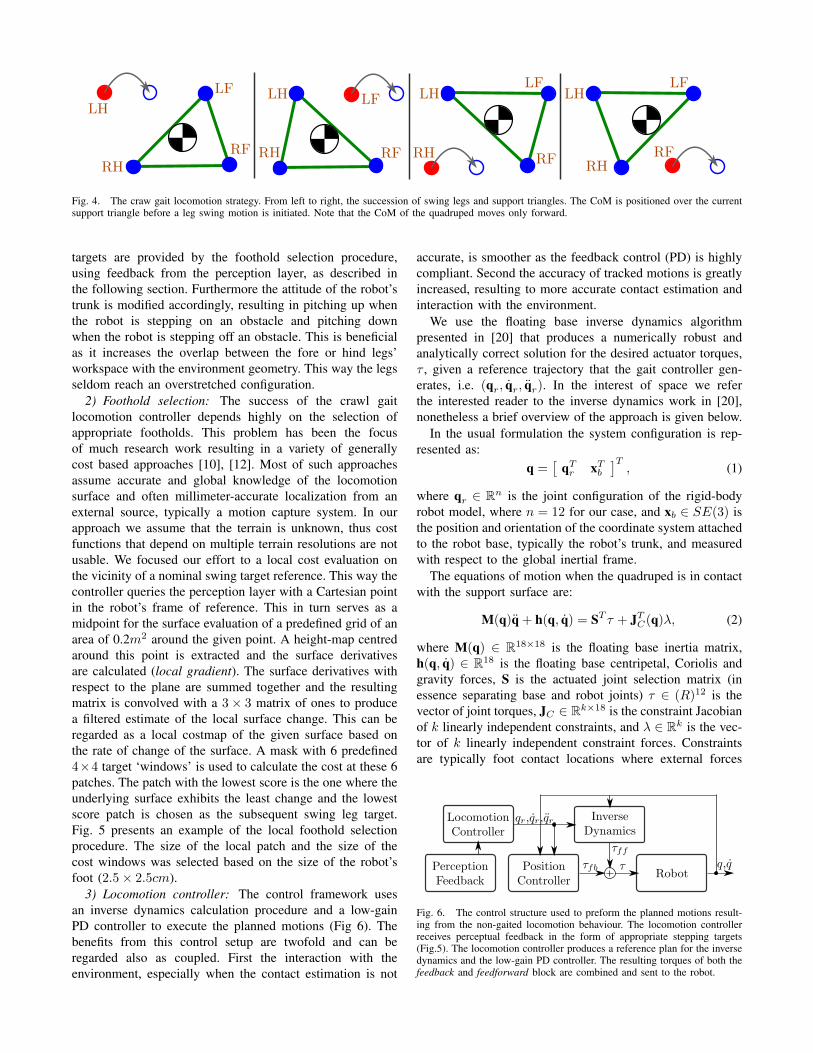
Fig. 4. The craw gait locomotion strategy. From left to right, the succession of swing legs and support triangles. The CoM is positioned over the currentsupport triangle before a leg swing motion is initiated. Note that the CoM of the quadruped moves only forward.
targets are provided by the foothold selection procedure,using feedback from the perception layer, as described inthe following section. Furthermore the attitude of the robot’strunk is modified accordingly, resulting in pitching up whenthe robot is stepping on an obstacle and pitching downwhen the robot is stepping off an obstacle. This is beneficialas it increases the overlap between the fore or hind legs’workspace with the environment geometry. This way the legsseldom reach an overstretched configuration.
2) Foothold selection: The success of the crawl gaitlocomotion controller depends highly on the selection ofappropriate footholds. This problem has been the focusof much research work resulting in a variety of generallycost based approaches [10], [12]. Most of such approachesassume accurate and global knowledge of the locomotionsurface and often millimeter-accurate localization from anexternal source, typically a motion capture system. In ourapproach we assume that the terrain is unknown, thus costfunctions that depend on multiple terrain resolutions are notusable. We focused our effort to a local cost evaluation onthe vicinity of a nominal swing target reference. This way thecontroller queries the perception layer with a Cartesian pointin the robot’s frame of reference. This in turn serves as amidpoint for the surface evaluation of a predefined grid of anarea of 0.2m2 around the given point. A height-map centredaround this point is extracted and the surface derivativesare calculated (local gradient). The surface derivatives withrespect to the plane are summed together and the resultingmatrix is convolved with a 3× 3 matrix of ones to producea filtered estimate of the local surface change. This can beregarded as a local costmap of the given surface based onthe rate of change of the surface. A mask with 6 predefined4×4 target ‘windows’ is used to calculate the cost at these 6patches. The patch with the lowest score is the one where theunderlying surface exhibits the least change and the lowestscore patch is chosen as the subsequent swing leg target.Fig. 5 presents an example of the local foothold selectionprocedure. The size of the local patch and the size of thecost windows was selected based on the size of the robot’sfoot (2.5× 2.5cm).
3) Locomotion controller: The control framework usesan inverse dynamics calculation procedure and a low-gainPD controller to execute the planned motions (Fig 6). Thebenefits from this control setup are twofold and can beregarded also as coupled. First the interaction with theenvironment, especially when the contact estimation is not
accurate, is smoother as the feedback control (PD) is highlycompliant. Second the accuracy of tracked motions is greatlyincreased, resulting to more accurate contact estimation andinteraction with the environment.
We use the floating base inverse dynamics algorithmpresented in [20] that produces a numerically robust andanalytically correct solution for the desired actuator torques,τ , given a reference trajectory that the gait controller gen-erates, i.e. (qr, qr, qr). In the interest of space we referthe interested reader to the inverse dynamics work in [20],nonetheless a brief overview of the approach is given below.
In the usual formulation the system configuration is rep-resented as:
q =[
qTr xT
b
]T, (1)
where qr ∈ Rn is the joint configuration of the rigid-bodyrobot model, where n = 12 for our case, and xb ∈ SE(3) isthe position and orientation of the coordinate system attachedto the robot base, typically the robot’s trunk, and measuredwith respect to the global inertial frame.
The equations of motion when the quadruped is in contactwith the support surface are:
M(q)q + h(q, q) = ST τ + JTC(q)λ, (2)
where M(q) ∈ R18×18 is the floating base inertia matrix,h(q, q) ∈ R18 is the floating base centripetal, Coriolis andgravity forces, S is the actuated joint selection matrix (inessence separating base and robot joints) τ ∈ (R)12 is thevector of joint torques, JC ∈ Rk×18 is the constraint Jacobianof k linearly independent constraints, and λ ∈ Rk is the vec-tor of k linearly independent constraint forces. Constraintsare typically foot contact locations where external forces
Fig. 6. The control structure used to preform the planned motions result-ing from the non-gaited locomotion behaviour. The locomotion controllerreceives perceptual feedback in the form of appropriate stepping targets(Fig.5). The locomotion controller produces a reference plan for the inversedynamics and the low-gain PD controller. The resulting torques of both thefeedback and feedforward block are combined and sent to the robot.
5
10
15
20
5
10
15
0
2
4
5
10
15
5
10
15
20
−0.500.5
5
10
15
5
10
15
00.51
5
10
15
5
10
15
0
5
05
1015
20
0
5
10
15
200
5
10
15
20
x(cm)y(cm)
z(cm
)
05
1015
20
0
5
10
15
200
5
10
15
20
x(cm)y(cm)
z(cm
)
Fig. 5. An overview of the local foothold selection procedure. From left to right; a 0.02× 0.02 surface around the nominal swing target is converted toa height map. The local gradients are then computed, note that the surface estimate and surface gradients are typically noisy. The combined local gradientis filtered with a 3× 3(cm) matrix and a mask with 6 equidistant windows is used to calculate the local cost of each of the 6 patches. The midpoint of thepatch with the lowest cost is chosen as the swing target. This way the quadruped avoids stepping near sudden surface height changes (steps) and promotesstepping on the most flat path that the local surface can provide. The size of the local patch and the size of the cost windows was selected based on thesize of the robot’s foot.
are applied to the floating base system, i.e. ground reactionforces (GRFs).
The solution is of the form,
τ = (SuQT ST )+SuQT [Mqd + h], (3)
where Su is a selection matrix and Q is the dynamicsprojection matrix that results from a QR decomposition ofthe control space.
One problem that the above formulation poses occurswhen contact conditions change. In that instant, the inversedynamics solution changes from one support triangle to thenext, something that can result in abrupt torque changes andcan potentially result to sudden jerks that can render thesystem off-balanced. As the contact conditions change in aplanned fashion we overcome this limitation by interpolatingbetween the two contact model solutions in a linear manner.
VI. EXPERIMENTAL RESULTS
We have carried out a set of experimental trials both insideour lab, locomoting on a treadmill, and outside, on relativelyflat concrete ground. In the latter case we have used woodenboards to simulate irregular terrain as well as a flat woodenconstruction of approximately 1m2 area and 15cm height.In this setting the quadruped is asked to move forward whileno overall -navigation level- planning was utilized.
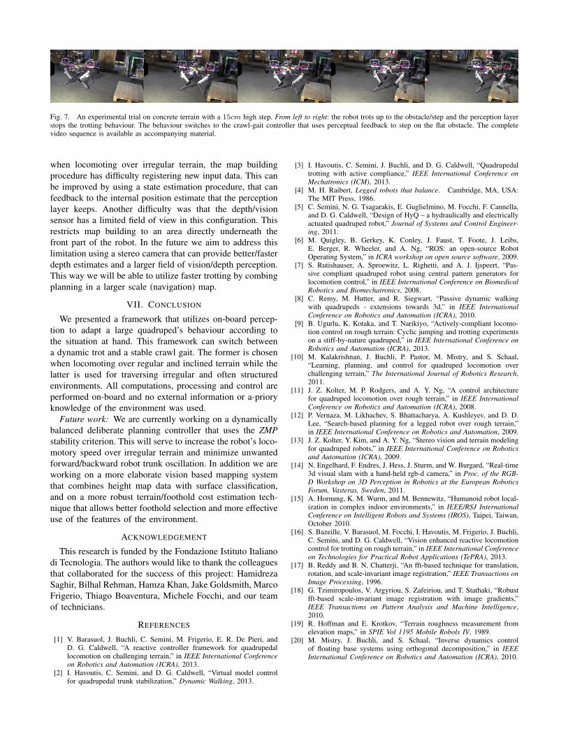
Trotting: The trotting controller as mentioned earlier isable to trot with a speed up to 0.5m/s according to the con-straints imposed by the perception layer. During trotting therobot can overcome obstacles up to 5cm without difficulty.This is achieved due to the controlled compliance of the legscombined with the trunk attitude corrective term as furtherdescribed in [1]. When the robot perceives obstacles that aretaller than 5cm the trotting controller is brought to a stopand the behaviour switches to the crawl gait.
Crawl-gait: The crawl gait is a slow locomotion behaviourwith emphasis on stable foot placement. The velocity of thetrunk in this mode never exceeds 0.05m/s in the forwarddirection as the motions are executed with strict stabilitybounds in mind. Nevertheless with this locomotion modewe have been able to overcome obstacles up to 0.15m, over20% of the HyQ’s leg in a fully extended configuration.Occasionally foot-slipping was observed, but this disturbancewas never large enough to impact the stability of the robot.
Perception: Overall the perception layer has been consis-tent while it operates with an average bandwidth of 15hz.When the crawl-gait controller queries the perception layerfor the next locally optimal foothold, it takes on average0.04s to complete this computation and to both-ways com-municate. In more detail, this is the time taken for the queryto be sent from the crawl-gait controller to the ROS layer,to transform the point to the appropriate reference frame,retrieve the local patch from the built map, calculate thelocally optimal point and reply back to the controller.
Data from a complete trial is presented in Fig.8. In thisexample the robot trots forward until it perceives an irregularobstacle. This results to a transition from trot to crawl wherethe robot needs to halt and reposition its legs accordingly.The crawl gait locomotion controller is then used and thetwo fore legs step on the obstacle. The data in Fig.8 is the z-axis position of the robot’s feet in the trunk (local) referenceframe. Snapshots from an experimental trial with a 15cmhigh step are presented in Fig. 7.
Limitations: We experimentally evaluated the trot con-troller to be utilized with speeds up to 0.5m/s. Neverthelessthe trot controller can locomote with a velocity up to 2.0m/s.When using a fast-paced trot (v > 0.5m/s), or sometimes
10 20 30 40 50 60
−0.6
−0.55
−0.5
−0.45
−0.4
−0.35
time(s)
z(m
)
LF foot
RF foot
LH foot
RH foot
Trot
Transition Crawl
Fig. 8. The transition from trotting to crawling gait as seen from the feetpositions in the robot’s trunk (local) coordinate frame. The robot perceivesan obstacle while trotting and its behaviour switches to the crawl gait. Theleft front foot then steps on the obstacle and the crawl gait cycle continues.
Fig. 7. An experimental trial on concrete terrain with a 15cm high step. From left to right: the robot trots up to the obstacle/step and the perception layerstops the trotting behaviour. The behaviour switches to the crawl-gait controller that uses perceptual feedback to step on the flat obstacle. The completevideo sequence is available as accompanying material.
when locomoting over irregular terrain, the map buildingprocedure has difficulty registering new input data. This canbe improved by using a state estimation procedure, that canfeedback to the internal position estimate that the perceptionlayer keeps. Another difficulty was that the depth/visionsensor has a limited field of view in this configuration. Thisrestricts map building to an area directly underneath thefront part of the robot. In the future we aim to address thislimitation using a stereo camera that can provide better/fasterdepth estimates and a larger field of vision/depth perception.This way we will be able to utilize faster trotting by combingplanning in a larger scale (navigation) map.
VII. CONCLUSION
We presented a framework that utilizes on-board percep-tion to adapt a large quadruped’s behaviour according tothe situation at hand. This framework can switch betweena dynamic trot and a stable crawl gait. The former is chosenwhen locomoting over regular and inclined terrain while thelatter is used for traversing irregular and often structuredenvironments. All computations, processing and control areperformed on-board and no external information or a-prioryknowledge of the environment was used.
Future work: We are currently working on a dynamicallybalanced deliberate planning controller that uses the ZMPstability criterion. This will serve to increase the robot’s loco-motory speed over irregular terrain and minimize unwantedforward/backward robot trunk oscillation. In addition we areworking on a more elaborate vision based mapping systemthat combines height map data with surface classification,and on a more robust terrain/foothold cost estimation tech-nique that allows better foothold selection and more effectiveuse of the features of the environment.
ACKNOWLEDGEMENT
This research is funded by the Fondazione Istituto Italianodi Tecnologia. The authors would like to thank the colleaguesthat collaborated for the success of this project: HamidrezaSaghir, Bilhal Rehman, Hamza Khan, Jake Goldsmith, MarcoFrigerio, Thiago Boaventura, Michele Focchi, and our teamof technicians.
REFERENCES
[1] V. Barasuol, J. Buchli, C. Semini, M. Frigerio, E. R. De Pieri, andD. G. Caldwell, “A reactive controller framework for quadrupedallocomotion on challenging terrain,” in IEEE International Conferenceon Robotics and Automation (ICRA), 2013.
[2] I. Havoutis, C. Semini, and D. G. Caldwell, “Virtual model controlfor quadrupedal trunk stabilization,” Dynamic Walking, 2013.
[3] I. Havoutis, C. Semini, J. Buchli, and D. G. Caldwell, “Quadrupedaltrotting with active compliance,” IEEE International Conference onMechatronics (ICM), 2013.
[4] M. H. Raibert, Legged robots that balance. Cambridge, MA, USA:The MIT Press, 1986.
[5] C. Semini, N. G. Tsagarakis, E. Guglielmino, M. Focchi, F. Cannella,and D. G. Caldwell, “Design of HyQ – a hydraulically and electricallyactuated quadruped robot,” Journal of Systems and Control Engineer-ing, 2011.
[6] M. Quigley, B. Gerkey, K. Conley, J. Faust, T. Foote, J. Leibs,E. Berger, R. Wheeler, and A. Ng, “ROS: an open-source RobotOperating System,” in ICRA workshop on open source software, 2009.
[7] S. Rutishauser, A. Sproewitz, L. Righetti, and A. J. Ijspeert, “Pas-sive compliant quadruped robot using central pattern generators forlocomotion control,” in IEEE International Conference on BiomedicalRobotics and Biomechatronics, 2008.
[8] C. Remy, M. Hutter, and R. Siegwart, “Passive dynamic walkingwith quadrupeds - extensions towards 3d,” in IEEE InternationalConference on Robotics and Automation (ICRA), 2010.
[9] B. Ugurlu, K. Kotaka, and T. Narikiyo, “Actively-compliant locomo-tion control on rough terrain: Cyclic jumping and trotting experimentson a stiff-by-nature quadruped,” in IEEE International Conference onRobotics and Automation (ICRA), 2013.
[10] M. Kalakrishnan, J. Buchli, P. Pastor, M. Mistry, and S. Schaal,“Learning, planning, and control for quadruped locomotion overchallenging terrain,” The International Journal of Robotics Research,2011.
[11] J. Z. Kolter, M. P. Rodgers, and A. Y. Ng, “A control architecturefor quadruped locomotion over rough terrain,” in IEEE InternationalConference on Robotics and Automation (ICRA), 2008.
[12] P. Vernaza, M. Likhachev, S. Bhattacharya, A. Kushleyev, and D. D.Lee, “Search-based planning for a legged robot over rough terrain,”in IEEE International Conference on Robotics and Automation, 2009.
[13] J. Z. Kolter, Y. Kim, and A. Y. Ng, “Stereo vision and terrain modelingfor quadruped robots,” in IEEE International Conference on Roboticsand Automation (ICRA), 2009.
[14] N. Engelhard, F. Endres, J. Hess, J. Sturm, and W. Burgard, “Real-time3d visual slam with a hand-held rgb-d camera,” in Proc. of the RGB-D Workshop on 3D Perception in Robotics at the European RoboticsForum, Vasteras, Sweden, 2011.
[15] A. Hornung, K. M. Wurm, and M. Bennewitz, “Humanoid robot local-ization in complex indoor environments,” in IEEE/RSJ InternationalConference on Intelligent Robots and Systems (IROS), Taipei, Taiwan,October 2010.
[16] S. Bazeille, V. Barasuol, M. Focchi, I. Havoutis, M. Frigerio, J. Buchli,C. Semini, and D. G. Caldwell, “Vision enhanced reactive locomotioncontrol for trotting on rough terrain,” in IEEE International Conferenceon Technologies for Practical Robot Applications (TePRA), 2013.
[17] B. Reddy and B. N. Chatterji, “An fft-based technique for translation,rotation, and scale-invariant image registration,” IEEE Transactions onImage Processing, 1996.
[18] G. Tzimiropoulos, V. Argyriou, S. Zafeiriou, and T. Stathaki, “Robustfft-based scale-invariant image registration with image gradients,”IEEE Transactions on Pattern Analysis and Machine Intelligence,2010.
[19] R. Hoffman and E. Krotkov, “Terrain roughness measurement fromelevation maps,” in SPIE Vol 1195 Mobile Robols IV, 1989.
[20] M. Mistry, J. Buchli, and S. Schaal, “Inverse dynamics controlof floating base systems using orthogonal decomposition,” in IEEEInternational Conference on Robotics and Automation (ICRA), 2010.