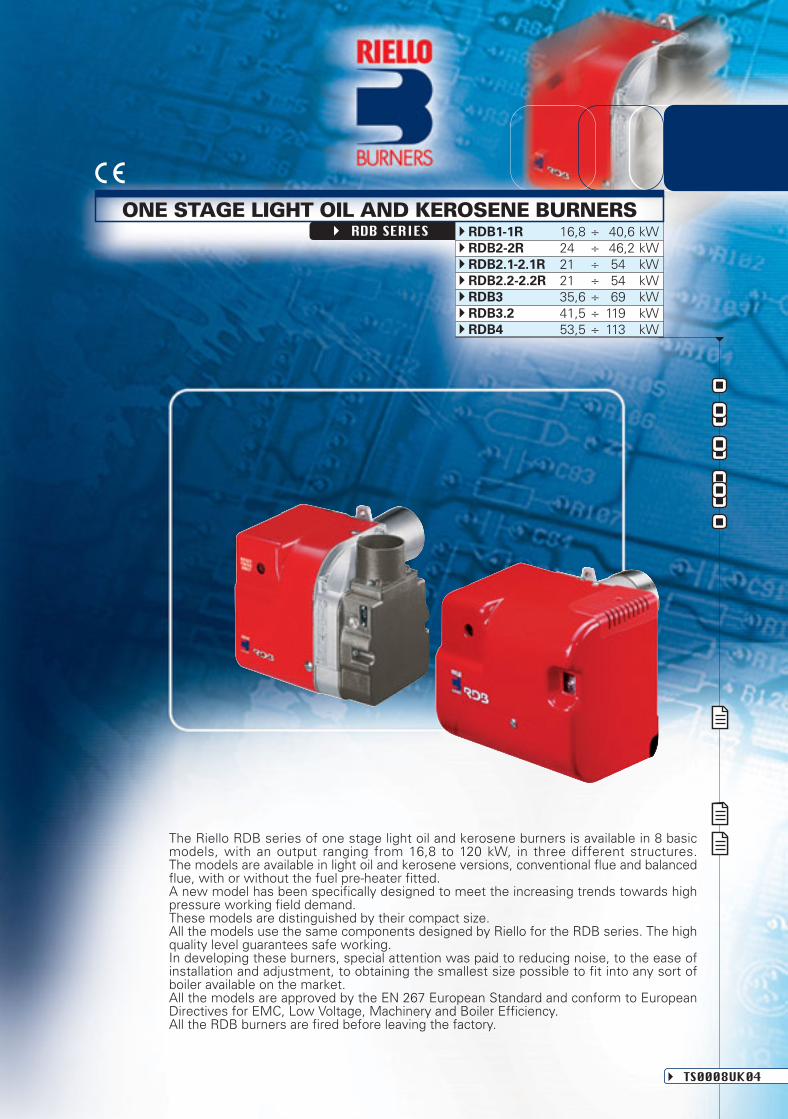
The Riello RDB series of one stage light oil and kerosene burners is available in 8 basic models, with an output ranging from 16,8 to 120 kW, in three different structures. The models are available in light oil and kerosene versions, conventional flue and balanced flue, with or without the fuel pre-heater fitted. A new model has been specifically designed to meet the increasing trends towards high pressure working field demand. These models are distinguished by their compact size. All the models use the same components designed by Riello for the RDB series. The high quality level guarantees safe working. In developing these burners, special attention was paid to reducing noise, to the ease of installation and adjustment, to obtaining the smallest size possible to fit into any sort of boiler available on the market. All the models are approved by the EN 267 European Standard and conform to European Directives for EMC, Low Voltage, Machinery and Boiler Efficiency. All the RDB burners are fired before leaving the factory. TS0008UK04 ONE STAGE LIGHT OIL AND KEROSENE BURNERS RDB SERIES RDB1-1R 16,8 ÷ 40,6 kW RDB2-2R 24, ÷ 46,2 kW RDB2.1-2.1R 21, ÷ 54 kW RDB2.2-2.2R 21, ÷ 54 kW RDB3 35,6 ÷ 69 kW RDB3.2 41,5 ÷ 119 kW RDB4 53,5 ÷ 113 kW
Transcript
The Riello RDB series of one stage light oil and kerosene burners is available in 8 basicmodels, with an output ranging from 16,8 to 120 kW, in three different structures.The models are available in light oil and kerosene versions, conventional flue and balancedflue, with or without the fuel pre-heater fitted.A new model has been specifically designed to meet the increasing trends towards highpressure working field demand.These models are distinguished by their compact size.All the models use the same components designed by Riello for the RDB series. The highquality level guarantees safe working.In developing these burners, special attention was paid to reducing noise, to the ease ofinstallation and adjustment, to obtaining the smallest size possible to fit into any sort ofboiler available on the market.All the models are approved by the EN 267 European Standard and conform to EuropeanDirectives for EMC, Low Voltage, Machinery and Boiler Efficiency.All the RDB burners are fired before leaving the factory.
TS0008UK04
ONE STAGE LIGHT OIL AND KEROSENE BURNERSRDB SERIES RDB1-1R 16,8 ÷ 40,6 kW
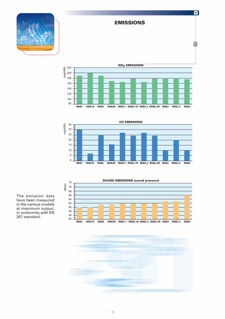
Reference conditions:Temperature: 20 °CPressure: 1013 mbarAltitude: 0 m a.s.l.Noise measured at a distance of 1 meter.
Since the Company is constantly engaged in the production improvement, the aesthetic and dimensional features, thetechnical data, the equipment and the accessories can be changed.This document contains confidential and proprietary information of RIELLO S.p.A. Unless authorised, this information shallnot be divulged, nor duplicated in whole or in part.
2
FIRING RATES
For every model (e.g. RDB1) are available many combustion heads which allow to optimizethe working field.
0
2
kW20
0
20
30
40
1
4
400 60 80 100 120
3
10
420 1 3 50
2
1
5
3
4
0
10
20
40
30
50
RDB3 RDB4
RDB3.2
RDB2.2 RDB2.2R
RDB2.1RRDB2.1
hP
a (m
bar
)
mm
H2O
hP
a (m
bar
)
mm
H2O
kW20 400 6010 30 50
Test conditions conforming to EN 267:Temperature: 20°CPressure: 1013 mbarAltitude: 0 m a.s.l.
Useful working field forchoosing the burner
Firing rate in progress
3
1086420 kg/h
0
0,5
0
5
10
15
1
1,5
RDB1RDB1R
hP
a (m
bar
)
mm
H2O
kW20 400 6010 30 50
420 1 3 5 kg/h
0
0,5
0
5
10
15
1
1,5
420 1 3 5
RDB2RRDB2
hP
a (m
bar
)
mm
H2O
kW20 400 6010 30 50
kg/h
kg/h
HYDRAULIC CIRCUIT
FUEL SUPPLY
All the models have a Riello geared pump with safety valve on thereturn circuit, and some are fitted with a fuel pre-heater.The kerosene models have a special kerosene pump, whichguarantees reliable operations with this type of fuel.
RDB - RDB R
Fuel pump
S
1
VR(NO)
2
T
S
VR(NO)
1
2
PH
U
Pump with filter and pressure regulator onthe delivery pipe
Oil return valve normally open
Oil input pipe to the nozzle
Oil return pipe from the regulator
Oil pre-heater with thermostat (where provided)
Nozzle
4
UPH
SELECTING THE FUEL SUPPLY LINES
The fuel feed must be completed with the safety devices required by the local regulations in force.
The table shows the choice of piping diameter for the various burners, depending on the differencein the height between the burner and the tank and the distance between them.
6
Type of system that can be installed
Pipe size
H (m)
0
0,5
1,0
1,5
2,0
3,0
3,5
Ø8mm
L max (m)
35
30
25
20
15
8
6
Ø10mm
L max (m)
100
100
100
90
70
30
20
Ø8mm
L max (m)
-
10
20
40
60
-
-
Ø10mm
L max (m)
-
20
40
80
100
-
-
Type A system
MAXIMUM EQUIVALENT LENGTH OF THE PIPEWORK L[m]
Type B system
Difference in height
Internal pipe diameter
Difference in height ≤ 4 m
Burner
Pump
Filter
Shut-off solenoid valve
Suction pipework
Bottom valve
Return pipework
H
Ø
P
1
2
3
4
5
6
7
HP
H
1
4
10 cm2
3
7 5 H
P
H
1
4
10 cm2
5
3
7
A
6
3
B
H
P
1
2
43
2
3
1
5
COMBUSTION HEAD
VENTILATION
The RDB series has been designed anddeveloped paying special attention toreducing noise levels, while guaranteeinghigh performance of pressure and airdelivery, inspite of their compact size.
Several types of combustion heads are available, to optimise all thevarious burner-boiler matchings.A simple adjustment to the combustion head (where fitted) allows adaptingsecondary air to the burner output.
Adjustable combustion head
Air suction
Dimensions of the flame
Fixed combustion head
Special attention has also been paid to the air-tightnessof the air circuit (this is also checked during the functionaltests to the burners on the production line); the air-tightnessis guaranteed by special technical solutions and seals, andis always conserved after any servicing operations.All the conventional flue models can be easily convertedto balanced flue, and vice versa, by using a special kit.
Example:Burner thermal output = 350 kW;L flame (m) = 1,2 m (medium value);D flame (m) = 0,6 m (medium value)
D
L
Burner output (kW)
Flam
e le
ng
th (
m)
Flam
e d
iam
eter
(m
)
0 200
1
100 300
2
400 500
0 0
0,5
1L max
L min
D max
D min
6
ADJUSTMENT
All these models are one stage operation; the special profile on theair-damper and its micrometric adjustment, ensure precise workingeven at the lowest output levels of the burner.
BURNER OPERATION MODE
The RDB burners can be fitted either with analogic control box RBL 535 SE/LD or with the newmicroprocessor control panel, MO535, which allows the the supervision during intermittentoperation.With reference to the MO 535 digital control panel, there are two main elements for helping thecommissioning and maintenance work:
The lock-out reset button is the central operating element for resetting the burner controland for activating / deactivating the diagnostic functions.
The multi-color LED is the central indication element for visual diagnosis and interfacediagnosis.
Both elements are located under the transparent cover of lock-out reset button, as showed below.
Switch
There are two diagnostic choices, for indication of operation and diagnosis of fault cause:
- visual diagnosis:
Ou
tpu
tC
hec
ked
var
iab
le bar°C
ON
OFF
time
time
ON
OFF
“One stage” operation
Air damper adjustmentAir damper
7
Switch
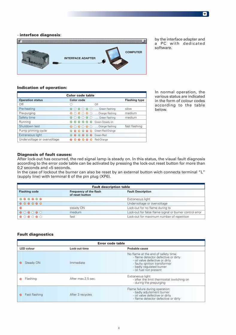
Indication of operation:In normal operation, thevarious status are indicatedin the form of colour codesaccording to the tablebelow.
Color code tableOperation status Color code Flashing type
Off Off
Pre-heating ….. Green flashing slowPre-purging ..…Orange flashing mediumSafety time ….. Green flashing mediumRunning Green-Steady on
Shutdown test ..…Orange flashing fast flashingPump priming cycle Green-Red-Orange
Extraneous light Green-Red Undervoltage or overvoltage Red-Orange
Fault diagnostics
Error code table
Probable cause
No flame at the end of safety time:- flame detector defective or dirty- oil valve defective or dirty- faulty ignition transformer- badly regulated burner- oil fuel not present
Extraneous light:- after the limit thermostat switching on- during the prepurging
Flame failure during operation:- badly adjutement burner- oil valve defective or dirty- flame detector defective or dirty
LED colour
Steady ON Immediate
Flashing After max.2,5 sec.
Fast flashing After 3 recycles
Lock-out time
- interface diagnosis: by the interface adapter anda PC with dedicatedsoftware.
COMPUTER
INTERFACE ADAPTER
8
Diagnosis of fault causes:After lock-out has occurred, the red signal lamp is steady on. In this status, the visual fault diagnosisaccording to the error code table can be activated by pressing the lock-out reset button for more than0,2 seconds and <5 seconds.In the case of lockout the burner can also be reset by an external button wich connects terminal “L”(supply line) with terminal 6 of the pin plug (XP6).
Fault description tableFlashing code Frequency of the flash Fault Description
of reset button
Extraneous lightUndervoltage or overvoltage
steady ON Lock-out for no flame during tsmedium Lock-out for false flame signal or burner control errorfast Lock-out for maximum number of repetition
The MO535 digital control box gives some other advantages:
RECYCLE FUNCTIONThe control box allows a recycle, i.e. complete repetition of the start-up programme, making up to 3attempts, in the event the flame failure during operation.If the flame failure again, this will cause the burner to lock out. If there is a new demand for heat duringthe recycle, the 3 attempts are reset when the limit thermostat (TL) switches.NOTE: After 510 seconds of continuous operation a new reignition possibility is added.By disconnecting power supply, when new heat demand occur (power supply is applied to the burner)all reignition possibilities are allowed (3 maximum).
LIMIT OF CONTINUOUS IGNITIONIn case of continuous ignition transformer recycling, the maximum permissible number of repetitionsis one attempt every minute.
IGNITION PREVENTED IN CASE OF EXTRANEOUS LIGHTIf extraneous light condition continues for more than 25 s, lock-out condition is reached.A new ignition attempt may occur by resetting the control box, when new heat demand occur (powersupply is applied to the burner).
SHUT-DOWN TESTIf the remote reset button is pressed during normal operation or during the start sequence for morethan 5s the unit will perform a shut-down. If the remote reset button is released, start up sequencebegins.
AUTOMATIC PUMP PRIMINGIn lock-out condition, the burner can be placed in a purge routine in order to purging air from oil linesand filters for 30 seconds. Repeat this function any 5 times to protect the pump.
Pump priming cycle can be deactivated before the end of “pump priming time” by repeating theactivation sequence.
LOCK-OUT AND RESETThe burner can be reset by pushing the built-in reset button for more than 0.2s (< 5s).In the case of lockout the burner can also be reset by an external button which connects terminal “L”(supply line) with terminal 6 of the pin plug (XP6).Attention: The burner can be reset only 5 times consecutively, then power supply has to be disconnectedfor a new 5 reset possibilities.The burner can only be reset if power supply is applied to the control box.
9
Automatic pump priming
Pump priming activation sequence Color code
The remote reset button must be pressed and held for more than 6s and afterwards released green / orange / redfast flashing
If then the remote reset button is pressed and afterwards released before 3s pump priming cycle starts green / orange / redflashing
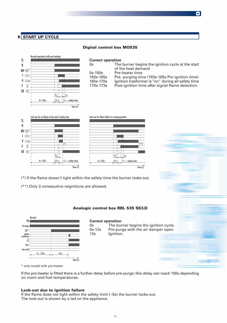
START UP CYCLE
Digital control box MO535
Correct operation0s The burner begins the ignition cycle at the start
of the heat demand0s-150s Pre-heater time150s-165s Pre- purging time (163s-165s Pre ignition time)165s-170s Ignition trasformer is “on” during all safety time170s-173s Post-ignition time after signal flame detection.
* only model with pre-heater
If the pre-heater is fitted there is a further delay before pre-purge; this delay can reach 150s dependingon room and fuel temperatures.
Lock-out due to ignition failureIf the flame does not light within the safety limit (~5s) the burner locks-out.The lock-out is shown by a led on the appliance.
Analogic control box RBL 535 SE/LD
Correct operation0s The burner begins the ignition cycle.0s-12s Pre-purge with the air damper open.12s Ignition.
(*) If the flame doesn’t light within the safety time the burner locks-out.
(**) Only 3 consecutive reignitions are allowed.
0 ÷ 150 s ~12 s
TR* Pre-heater
M
V
Ignitiontransformer
Lock-out led
Normal
time (s)
M
TL
MVIV
SB
Time (s)
K
F
M
TL
MVIV
SB
Time (s)
K
F
Time (s)
15 s
Normal operation (with pre-heating)
5 s = safety time0÷150 s
2 s 3 s
15 s
Lock-out for no flame at the end of safety time
5 s = safety time0÷150 s
2 s
(*)
Lock-out for flame failure in running position
15 s 5 s = safety time0÷150 s
2 s 3 s
(**)
10
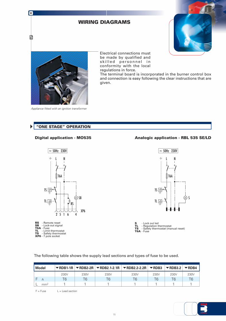
Electrical connections mustbe made by qualified ands k i l l e d p e r s o n n e l i nconformity with the localregulations in force.The terminal board is incorporated in the burner control boxand connection is easy following the clear instructions that aregiven.
WIRING DIAGRAMS
Appliance fitted with an ignition transformer
The following table shows the supply lead sections and types of fuse to be used.
“ONE STAGE” OPERATION
Digital application - MO535 Analogic application - RBL 535 SE/LD
Skilled and qualified personnel must perform installation, startup and maintenance.A nozzle is fitted to the burner and used for fire tests in thefactory. If necessary, change the nozzle on the basis of themaximum output of the boiler.All operations must be carried out as described in the technicalhandbook supplied with the burner.
Head setting area is easily accessible and the operationis simple thanks to a graduated scale.
RDB series burners can be adjusted from the back ofthe burner just using a single tool; the air damper iseasily adjustable (thanks to a micrometric screw and aposition indicator) without removing the burner cover.
In models RDB3 and RDB4, the maintenance positionis easily carried out by hooking the burner to the flange,after removing it from the fixing screws.
Maintenance is easy because all the components,including the combustion head, are easily accessed byjust unscrewing a single nut.
The main components - the control box, motor andpump - are outside the air circuit, thus avoiding anyrisk of oil build up inside the circuit.
All the electrical components are connected by socket-plugs and they are easy to reach for controls.
BURNER SETTING
MAINTENANCE
14
BURNER ACCESSORIES
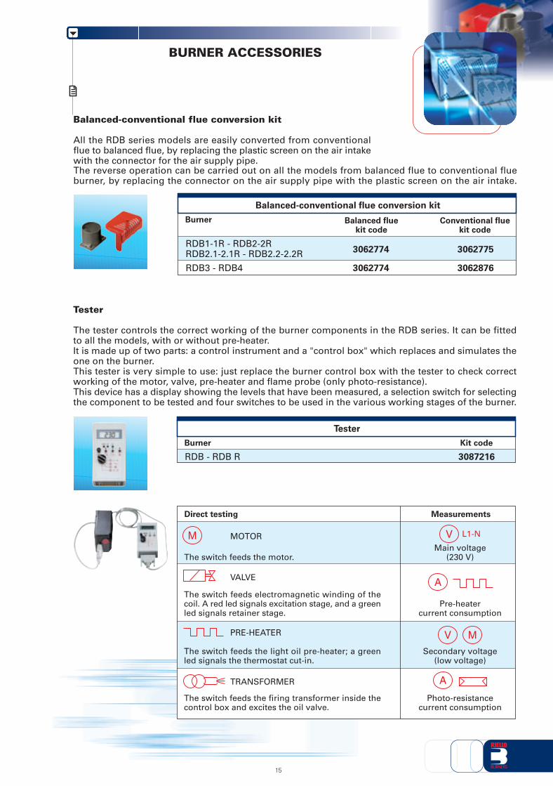
Balanced-conventional flue conversion kit
All the RDB series models are easily converted from conventionalflue to balanced flue, by replacing the plastic screen on the air intakewith the connector for the air supply pipe.
Balanced fluekit code
3062774
3062774
RDB1-1R - RDB2-2RRDB2.1-2.1R - RDB2.2-2.2R
RDB3 - RDB4
Burner
Balanced-conventional flue conversion kit
The reverse operation can be carried out on all the models from balanced flue to conventional flueburner, by replacing the connector on the air supply pipe with the plastic screen on the air intake.
Conventional fluekit code
3062775
3062876
Tester
The tester controls the correct working of the burner components in the RDB series. It can be fittedto all the models, with or without pre-heater.It is made up of two parts: a control instrument and a "control box" which replaces and simulates theone on the burner.This tester is very simple to use: just replace the burner control box with the tester to check correctworking of the motor, valve, pre-heater and flame probe (only photo-resistance).This device has a display showing the levels that have been measured, a selection switch for selectingthe component to be tested and four switches to be used in the various working stages of the burner.
Kit code
3087216RDB - RDB R
Burner
Tester
Measurements
MOTOR
Direct testing
Main voltage(230 V)
VALVE
Pre-heatercurrent consumption
The switch feeds the motor.
The switch feeds electromagnetic winding of thecoil. A red led signals excitation stage, and a greenled signals retainer stage.
PRE-HEATER
Secondary voltage(low voltage)
The switch feeds the light oil pre-heater; a greenled signals the thermostat cut-in.
TRANSFORMER
Photo-resistancecurrent consumption
The switch feeds the firing transformer inside thecontrol box and excites the oil valve.
M L1-NV
V M
A
A
15
Extended head kit
Kit code
3004590RDB4 111
Standard headlength (mm)
170
Extended headlength (mm)
Kit codeBurner
3006561All modelsFiltering degree (μm)
60
Filter made up of aluminium body and stainless steel filtering cartridge; available singularly.
For cleaning light oil from dirty particles and impurities filters with the following features are available:
Light oil filter
Light oil filter/degassing unit
To solve problems of air or water in the oil circuit a special filter/degassing unit is available, made upof aluminium cover, plastic tank, stainless steel filtering cartridge, air release cap and water purgevalve. It is available singularly.
Burner
Extended head kit
Burner
Light oil filter/degassing unit
Kit code
3000926All modelsFiltering degree (μm)
100
Light oil filter
Light oil filter
Filter made up of aluminium cover, plastic tank and nylon filtering cartridge; available in packagingof 50 pieces.
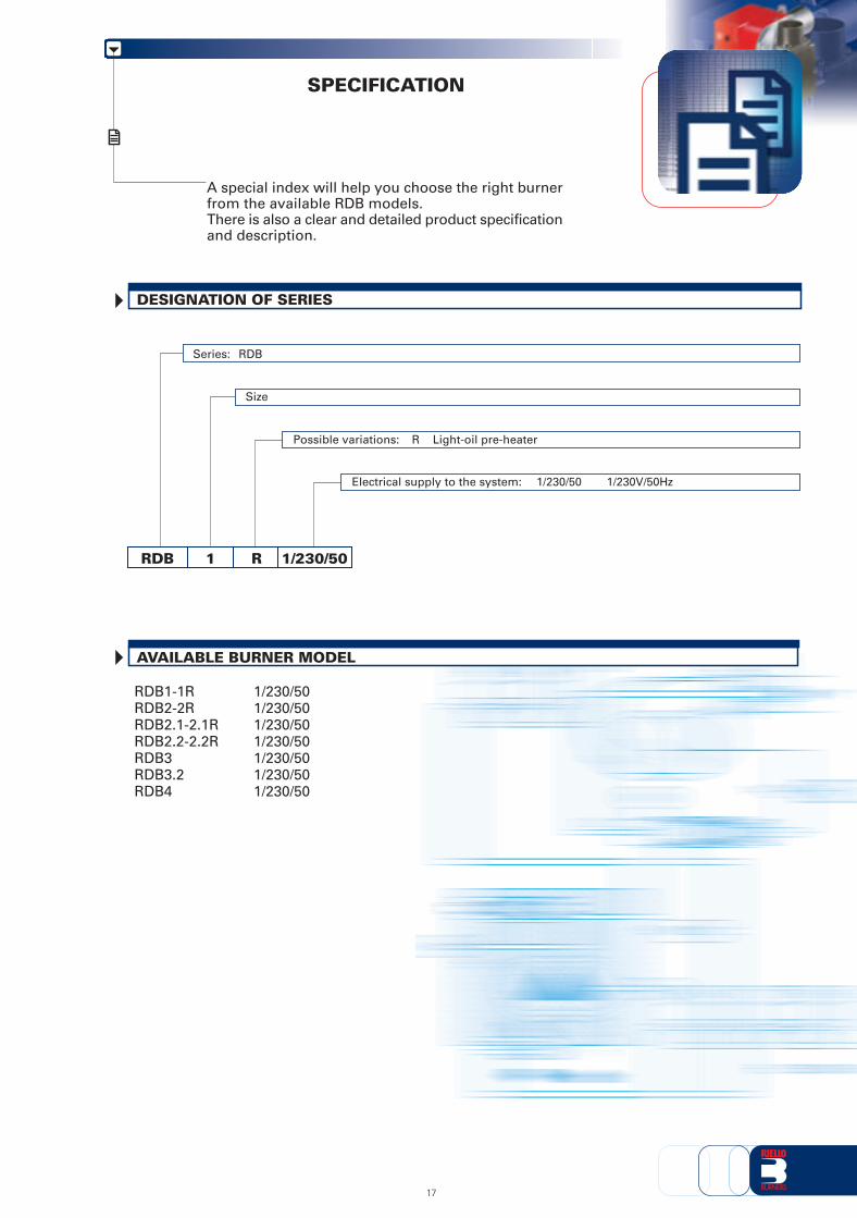
A special index will help you choose the right burnerfrom the available RDB models.There is also a clear and detailed product specificationand description.
Electrical supply to the system: 1/230/50 1/230V/50Hz
17
PRODUCT SPECIFICATION
Burner
Completely automatic monobloc light oil and kerosene burners, with single-stage operation fittedwith:- Fan with forward inclined blades- Air damper with external adjustment, with no need to remove the cover- Air-tight air circuit, also available in the balanced flue version- Single phase electric motor 230 V, 50 Hz- Combustion head fitted with:
- stainless steel head cone, resistant to high temperatures- ignition electrodes- flame stability disk
- Geared pump (specific version for kerosene) for fuel supply, fitted with filter- pressure regulator- attachments for fitting a pressure gauge and vacuum meter
- internal by-pass for preparing for single-pipe installations- Fuel feed solenoid valve incorporated in the pump- Photocell for flame detection- Electronic flame control equipment available with MO 535 (on demand)- Protective filter against radio interference- Light oil nozzle- IP X0D protection level- Fuel pre-heater (optional).
Standard equipment:- Two flexible pipes for connection to the light oil supply line- Two nipples for connection to the pump- Flange, screws and nuts for fixing- Thermal screen- Air intake- Protection grill- Exagonal key- Instruction handbook for installation, use and maintenance- Spare parts list.
Available accessories to be ordered separately:- Balanced-conventional flue conversion kit- Tester- Light oil filter- Light oil filter/ degassing unit- Extended head kit (only for RDB4).
18
19
RIELLO S.p.A. - Via Ing. Pilade Riello, 5 - 37045 Legnago (VR) ItalyTel. ++39.0442630111 - Fax ++39.044221980
Internet: http://www.rielloburners.com - E-mail: [email protected] 9001 Cert. n. 0061
Since the Company is constantly engaged in the production improvement, the aesthetic anddimensional features, the technical data, the equipment and the accessories can be changed.
This document contains confidential and proprietary information of RIELLO S.p.A.Unless authorised, this information shall not be divulged, nor duplicated in whole or in part.