21
BULLETIN 7703E www.klinkmann.com 6 / 2011

BULLETIN 7703E
www.klinkmann.com6 / 2011

Because of the variety of uses for the products described in this publication, those responsible for the application and use of this control equipment must satisfy themselves that all necessary steps have been taken to assure that each application and use meets all performance and safety requirements, including any applicable laws, regulations, codes and standards.
The illustrations, charts, sample programs and layout examples shown in this guide are intended solely for purposes of example. Since there are many variables and requirements associated with any particular installation, Rockwell Automation does not assume responsibility or liability (to include intellectual property liability) for actual use based upon the examples shown in this publication.
Important User Information

Table of Contents
7703E SMC OEM Components
Description ....................................................................................................1
Standard Control Module ............................................................................. 1
Optional Control Module .............................................................................. 1
Features ...................................................................................................... 1
Optional Communication Modules ............................................................... 1
Product Selection Guide – 10-15 kV ............................................................ 1
Typical Power System Diagram – 10-15 kV ................................................ 2
Typical Power Circuit – Standard Module (10-15 kV) .................................. 3
Functional Design Specifications ................................................................. 4
7703E OEM Component Kits
PowerBrick™ ............................................................................................... 5
Description ........................................................................................... 5
Specifications ....................................................................................... 5
Options and Catalog Numbers ............................................................. 6
Typical Mounting Arrangement for 10-12 kV PowerBrick System ........ 8
Voltage Sensing Board ................................................................................ 9
Description ........................................................................................... 9
Catalog Number ................................................................................... 9
Interface Board .......................................................................................... 10
Description ......................................................................................... 10
Specifications ..................................................................................... 10
Catalog Number ................................................................................. 10
Fiber Optic Multiplexer Board .................................................................... 11
Description ......................................................................................... 11
Specifications ..................................................................................... 11
Catalog Number ................................................................................. 11
SMC Flex Control Module .......................................................................... 12
Description ......................................................................................... 12
Starting and Stopping Options ............................................................ 12
Specifications ..................................................................................... 12
Dimensions ......................................................................................... 13
Options and Catalog Numbers ........................................................... 13
Fiber Optics ............................................................................................... 14
Description ......................................................................................... 14
Specifications ..................................................................................... 14
Options and Catalog Numbers ........................................................... 14
Gate Driver Test Power Supply ................................................................. 15
Description ......................................................................................... 15
Specifications ..................................................................................... 15
Options and Catalog Numbers ........................................................... 15

Overview
Rockwell Automation has produced quality Medium Voltage products to meet the
requirements of all types of industries for well over six decades.
From the original oil-immersed contactor to air break and vacuum contactors, to solid-state
controllers such as Smart Motor Controllers and AC Variable Frequency Drives, Rockwell
Automation has developed and built a medium voltage product line that satisfies industries who
are demanding more safety, less maintenance, longer life and reliability in motor control equipment.
Added to those demands is the need for smaller, more flexible medium voltage products that
are more efficient and reduce building and expansion costs.
OEM frames and components leverage the existing family of motor controllers built by
Rockwell Automation. They also incorporate some of the most fundamental, high volume
components available in our OEM product line for Original Equipment Manufacturers and
electrical equipment companies.
Bulletin 1502 vacuum contactors are a comprehensive line of vacuum contactors used as
isolating contactors or as bypass contactors. Light weight and maintainability are but two of
the features of this fixed-mounted design.
Bulletin 1503F OEM components are a series of medium voltage frame-mounted
components designed to mount into new or existing structures or enclosures. These
assemblies can also be used to retrofit existing motor controllers. These products are
available as a complete OEM frame or sold individually as components.
Bulletin 1503E MV SMC™ Flex OEM kits are a series of solid-state reduced voltage
components designed to mount into new or existing structures or enclosures. These
assemblies can also be used to retrofit existing motor controllers. These products are
available as an OEM frame and components.
Bulletin 857 is a motor/feeder protection relay that includes all the essential functions
needed to protect motors and feeders in diverse industrial applications. The programmable
857 includes the optional arc protection feature, thermal, trip circuit supervision and circuit
breaker protection. The device can include numerous communication protocols, as well as a
twelve-channel RTD scanner.
Bulletin 865 is a differential protection relay that includes the necessary functions to protect
transformers for distribution networks of utilities, industry power plants and offshore
applications, as well as motor and generator differential protection. The device’s
programmable functions include thermal and circuit breaker protection, and numerous
communications protocols. An optional arc flash protection is available.
Rockwell Automation also offers standard motor controllers, solid-state reduced voltage
starters, and variable speed drives with standard, yet flexible, product configurations for all
product lines.
Rockwell Automation offers several OEM programs, such as customer-specific program
(custom engineered options and configurations with a standard quick-ship delivery). Contact
your local Rockwell Automation office for more information on these programs and other
OEM products.

1
Description
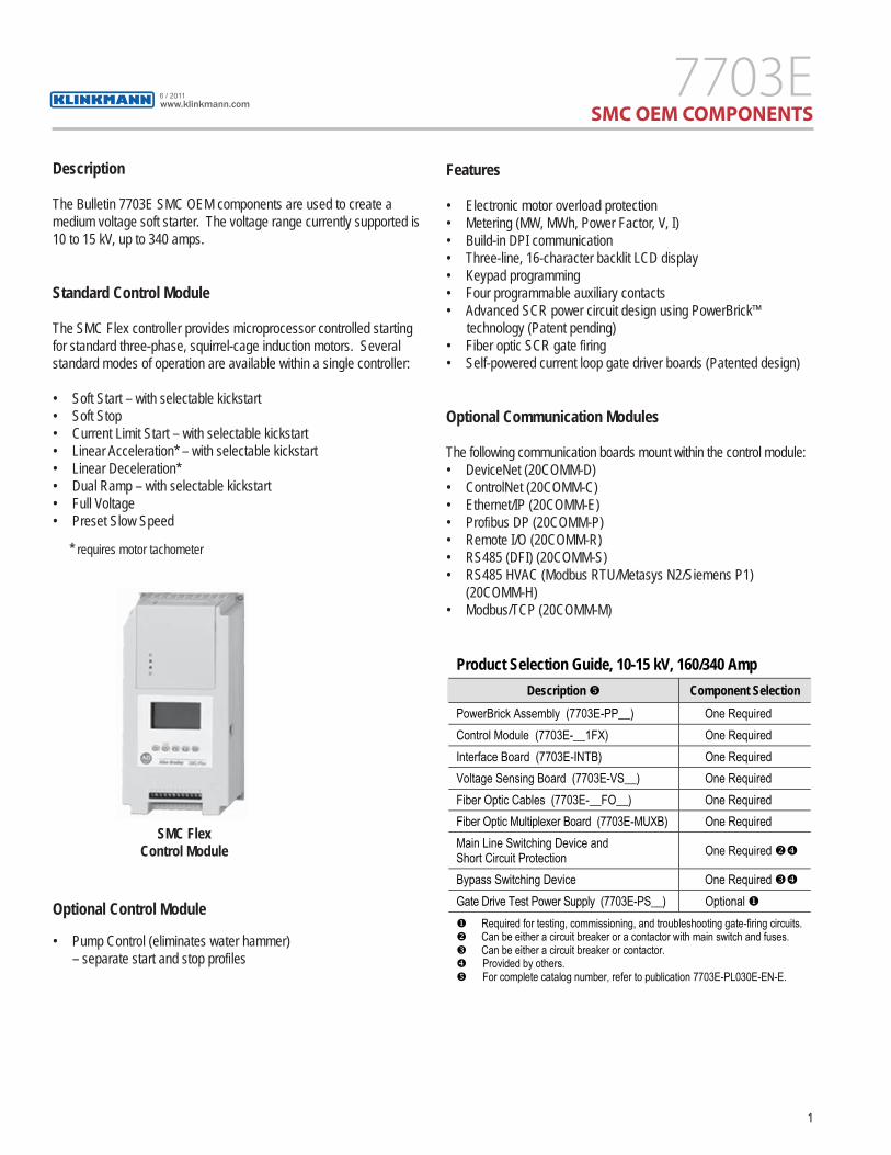
The Bulletin 7703E SMC OEM components are used to create a medium voltage soft starter. The voltage range currently supported is 10 to 15 kV, up to 340 amps.
Standard Control Module
The SMC Flex controller provides microprocessor controlled starting for standard three-phase, squirrel-cage induction motors. Several standard modes of operation are available within a single controller:
• Soft Start – with selectable kickstart • Soft Stop• Current Limit Start – with selectable kickstart• Linear Acceleration* – with selectable kickstart• Linear Deceleration* • Dual Ramp – with selectable kickstart • Full Voltage• Preset Slow Speed
* requires motor tachometer
Optional Control Module
• Pump Control (eliminates water hammer) – separate start and stop profi les
Features
• Electronic motor overload protection• Metering (MW, MWh, Power Factor, V, I)• Build-in DPI communication• Three-line, 16-character backlit LCD display• Keypad programming• Four programmable auxiliary contacts• Advanced SCR power circuit design using PowerBrick™
technology (Patent pending)• Fiber optic SCR gate fi ring• Self-powered current loop gate driver boards (Patented design)
Optional Communication Modules
The following communication boards mount within the control module:• DeviceNet (20COMM-D)• ControlNet (20COMM-C)• Ethernet/IP (20COMM-E)• Profi bus DP (20COMM-P)• Remote I/O (20COMM-R)• RS485 (DFI) (20COMM-S)• RS485 HVAC (Modbus RTU/Metasys N2/Siemens P1) (20COMM-H)• Modbus/TCP (20COMM-M)
SMC Flex Control Module
Product Selection Guide, 10-15 kV, 160/340 Amp Description � Component Selection
PowerBrick Assembly (7703E-PP__) One Required Control Module (7703E-__1FX) One Required Interface Board (7703E-INTB) One Required Voltage Sensing Board (7703E-VS__) One Required Fiber Optic Cables (7703E-__FO__) One Required Fiber Optic Multiplexer Board (7703E-MUXB) One Required Main Line Switching Device and Short Circuit Protection One Required ��
Bypass Switching Device One Required ��Gate Drive Test Power Supply (7703E-PS__) Optional �� Required for testing, commissioning, and troubleshooting gate-firing circuits. � Can be either a circuit breaker or a contactor with main switch and fuses. � Can be either a circuit breaker or contactor. � Provided by others. � For complete catalog number, refer to publication 7703E-PL030E-EN-E.
www.klinkmann.com6 / 2011

2
Typical Power System Diagram – 10-15 kV (Requires short circuit protection, as well as Start and Bypass switching devices)
L1
L2
GRD
L3
24C
PHAS
E A
PHAS
E B
PHAS
E C
FO3
FO2
FO1
FO4-
15FO
16-2
7FO
28-3
9
GND2
GND1
J1
1 2 3 4 5 6
POWERIN
GNL1TB1
GATE
TRA
NSMI
TTER
S TB6
ØA
U16
U18
U20
TEMP.GATE TRANSMITTERS
ØBTX
7
GDPS
TX1
VSB
TB21
GL2/NL1
POWERIN
TB1
ØCTX
13
-RS
1-R
S n
TO S
MC F
LEX
CT IN
PUTS
CT INPUTS
C+A- A+ B+B-TB5
C-J3
-QB
-QB
-QE
FROM
CONT
ROL
CIRC
UIT
SMC
FLEX
CONT
ROL
MODU
LELOOP
CT
FROM
CUR
RENT
MTR
FROM
CONT
ROL
CIRC
UIT
2
1
OV1
C1S1
OV2
RR1/2
RS1/2
/3
C2S2
CS
RX1
GTX
1C
T
-GP1
TEST
-BC
-+
OVS
C
RX1
TX1
TC
GOV
-BC
TEST
+-
-GP2S
C
G1G2
TT
G2
2
1
C1S1
RS1/2
/3
C2S2
CS
G1
TT
RX1
GTX
1C
T
-GP2
TEST
-BC
-+
OVS
C
RX1
TX1
TC
GOV
-BC
TEST
+-
-GP1S
C
OV2
OV1
RR1/2
RX
-KF1
-KF2
TO
FROM
STA
RTCO
NTRO
LLER
PHAS
E CT
S
STAR
T CO
NTRO
LLER
BYPA
SS C
ONTR
OLLE
R
POW
ER C
ONVE
RTER
- CUR
RENT
LOOP
GAT
E DR
IVER
BOA
RD-G
P
- SMC
FLE
X IN
TERF
ACE
BOAR
D-K
F2-BC
- SMC
FLE
X FI
BRE
OPTI
C BO
ARD
-KF1
- CUR
RENT
TRA
NSFO
RMER
- CIR
CUIT
BRE
AKER
-QB
- EAR
THIN
G SW
ITCH
(OPT
IONA
L EQU
IPME
NT)
-QE
- SMC
FLE
X PO
WER
BRIC
K AS
SEMB
LY-R
S
- VOL
TAGE
SEN
SING
BOA
RD-B
V
WIR
E CO
NNEC
TION
S FO
R PH
ASE
A
CONN
ECTI
ONS
SHOW
N FO
R PH
ASE
C
LEGE
ND
WIR
E CO
NNEC
TION
S FO
R PH
ASE
B
ON T
HE C
URRE
NT LO
OP A
SSEM
BLY
CURR
ENT
LOOP
CON
DUCT
ORS
PASS
THR
OUGH
THE
C.T
.'S
REMO
TE E
QUIP
MENT
VOLT
AGE
NUMB
ER O
F
10-1
2kV
512
.1-14
.4kV
6
INCO
MING
LINE
UNIT
INCO
MING
LINE
CUST
OMER
'S
L3L2L1
1
-BC2
-BC1
-BC3
-BC2
-BC1
-BC3
-BV
T3T2T1
POWEROUT
www.klinkmann.com6 / 2011

3
Typical Control Circuit – Standard Module (10-15 kV)(Requires a Start and Bypass switching device, control panels, as well as control relays and pilot devices)
-BC4
LEGEND
CURRENT LOOP CONDUCTORS PASS THROUGH THE C.T.'S
ØA ØB ØC
TO SMC FLEXINTERFACE
INTERFACE BOARD
STOPSTART
H1 H3 H2 H4
230V
OR
CONTROL POWER
START/STOP SIGNAL
BYPASS CONTROLLERPILOT CONTROL RELAY
START CONTROLLER
- CURRENT LOOP TRANSFORMER-TT1
- MINIATURE CIRCUIT BREAKER OR CONTROL FUSE-FB
29 3028272524 2623 33 34
201918171514 161311 12
SMCTM FLEX
DPI
21 22
31 32
CONTROL TERMINALS
GROUNDFAULT
TACHINPUT
PTCINPUT
-FB
-FB
-TT1
H1 H3 H2 H4
X1 X2
115V
BOARD -TB6-BC4
FROM SMC FLEX
CONTROL RELAY
PILOT CONTROL RELAY
-KG1
-KG1
-KG3
AUX.1UP-TO-SPEED
AUX.4NORMAL
AUX.2FAULT
AUX.3ALARM
SMC FLEX TO BE PROGRAMMED BYTHE CUSTOMERBEFORE START-UP
- BYPASS CONTROLLER PILOT CONTROL RELAY-KG2
- START/STOP SIGNAL CONTROL RELAY-KG1
- START CONTROLLER PILOT CONTROL RELAY-KG3
-KG3
- CURRENT LOOP CURRENT SENSORON THE CURRENT LOOP ASSEMBLY
SMC FLEX FIBER OPTIC BOARDPOWER IN
-KG3
-KG2
-KG1
SMC FLEX INTERFACE BOARDPOWER IN
R
www.klinkmann.com6 / 2011

4
Functional Design Specifications Features Description
Power Wiring The MV SMC Flex Controller must be wired with a start contactor or circuit breaker as per local/regional codes. A bypass contactor or circuit breaker must be employed after the controller has brought the motor to full speed. Installation
Control Wiring 2- and 3-wire control for a wide variety of applications.
Keypad The MV SMC Flex Controller is configured with the front keypad and backlit LCD display.
Set-up Software
Parameter values can be downloaded to the MV SMC Flex Controller with Drive Tools programming software and an optional (20COMM-x) communication module.
Communications (two ports) One serial (DPI) port provided for connection to optional human interface One serial (DPI) port provided for optional 20-COMMx modules (mounted within SMC Flex control module)
Starting Modes Soft Start with selectable kickstart, Soft Stop, Current Limit Start with selectable kickstart, Linear Acceleration with selectable kickstart, Linear Deceleration, Dual Ramp with selectable kickstart, Full Voltage, Preset Slow Speed
Protection and Diagnostics Power loss, line fault, voltage unbalance, current unbalance, excessive starts/hour, phase reversal, undervoltage, overvoltage, controller temperature, stall, jam, open gate, overload, underload, communication fault, ground fault
Metering Amps, volts, elapsed time, motor thermal capacity usage, power (MW, MWh, PF) Status Indication Stopped, ramping, stopping, at speed, and fault.
Auxiliary Contacts One single-pole, double-throw contact programmable as normal or External Bypass; one contact programmable as normal or fault.
Control Voltage 110/120 V AC to 220/240 V AC; 50/60 Hz
Fibre Optic Cables Available in two lengths (2.5 m and 5.0 m). Provides isolation between interface board and power stacks.
Standard Features
Soft Stop Extended coast-to-rest to minimize load shifting. Ramp down time may be adjusted. �
Pump Control Helps reduce fluid surges in centrifugal pumping systems during starting and stopping period. Starting time is adjustable from 0 to 30 seconds. Depending on application, stopping time may be adjusted. �Optional
Features Communication Modules DeviceNet, ControlNet, Ethernet/IP, Profibus DP, Remote I/O, RS485 (DF1),
RS485 (Modbus RTU, Metasys N2, Siemens P1), Modbus/TCP � Thermal capacity limits must not be exceeded.
The combined maximum ratings for MV SMC Flex units are as follows: • 30 second Start/Stop • 40°C Ambient temperature • 2 Start/Stop in an hour • 450% FLC (average during starting) If any of the above maximums are not required, it is generally possible to exceed some of the other ratings. Please consult factory for details.
www.klinkmann.com6 / 2011
5
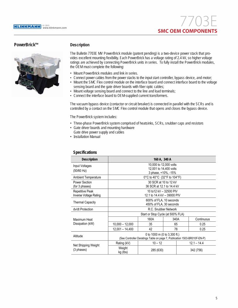
PowerBrick™ Description
The Bulletin 7703E MV PowerBrick module (patent pending) is a two-device power stack that pro-vides excellent mounting fl exibility. Each PowerBrick has a voltage rating of 2.4 kV, so higher voltage ratings are achieved by connecting PowerBrick units in series. To fully install the PowerBrick modules, the OEM must complete the following: • Mount PowerBrick modules and link in series.
• Connect power cables from the power stacks to the input start controller, bypass device, and motor;• Mount the SMC Flex control module on the interface board and connect interface board to the voltage
sensing board and the gate driver boards with fi ber optic cables; • Mount voltage sensing board and connect to the line and load terminals; • Connect the interface board to OEM-supplied current transformers.
The vacuum bypass device (contactor or circuit breaker) is connected in parallel with the SCRs and is controlled by a contact on the SMC Flex control module that opens and closes the bypass device.
The PowerBrick system includes:• Three-phase PowerBrick system comprised of heatsinks, SCRs, snubber caps and resistors• Gate driver boards and mounting hardware Gate drive power supply and cables
• Installation Manual
SpecificationsDescription 160 A, 340 A
Input Voltages (50/60 Hz)
10,000 to 12,000 volts 12,001 to 14,400 volts 3 phase, +10%, -15%
Ambient Temperature 0°C to 40°C (32°F to 104°F) Power Section (for 3 phases)
30 SCR at 10 to 12 kV 36 SCR at 12.1 to 14.4 kV
Repetitive Peak Inverse Voltage Rating
10 to12 kV – 32500 PIV 12.1 to 14.4 kV – 39000 PIV
Thermal Capacity 600% of FLA, 10 seconds 450% of FLA, 30 seconds
dv/dt Protection R.C. Snubber Network Start or Stop Cycle (at 500% FLA)
160A 340A Continuous 10,000 – 12,000 35 65 0.25
Maximum Heat Dissipation (kW)
12,001 – 14,400 42 78 0.25
Altitude 0 to 1000 m (0 to 3,300 ft.) (See Controller Deratings Table on page 7, Publication 1503-BR010F-EN-P)
Rating (kV) 10 – 12 12.1 – 14.4 Net Shipping Weight (3 phases) Weight
kg (lbs) 285 (630) 342 (756)
www.klinkmann.com6 / 2011

6
PowerBrick - 3D View
PowerBrick2400V, 200/400 A
PowerBrick™ Options and Catalog Numbers ���
Line Voltage � Size (Amps) � Catalog Number �160 7703E-PPMT 12 kV 340 7703E-PPMA 160 7703E-PPNT 15 kV 340 7703E-PPNA
� Includes transformer for current loop gate driver system. Wiring to be supplied by OEM. � 3 phase, 50/60 Hz. – 12 kV can be used for motor voltage from 10 to 12 kV, includes 5 PowerBrick units per phase – 15 kV can be used for motor voltage from 12.1 to 14.4 kV, includes 6 PowerBrick units per phase � Nominal motor full load current. May require derating depending on enclosure type, ambient
and application conditions. � The following components are also required to complete one unit kit:
– One of 7703E-S1FX or 7703E-B1FX – One 7703E-INTB – One 7703E-MUXB – One 7703E-VSM or 7703E-VSN
– One of 7703E-xxFOxx � Additional hardware is required for main and bypass switching and circuit protection (not
supplied by Rockwell Automation). PowerBrick units are rated for starting duty only, and must be bypassed after the motor reaches full speed.
� Current loop CT assembly included.
www.klinkmann.com6 / 2011

7
Front View Side View
Current Loop Gate Drive Cable(mounts on PowerBricks)
Current Loop Gate Drive Cable(mounts on PowerBricks)
Current Loop Gate Drive Cable(mounts on PowerBricks)
www.klinkmann.com6 / 2011

8
Typical Mounting Arrangementfor 10-12 kV PowerBrick System
Note: For 12-15 kV PowerBrick system, an additional PowerBrick is required per phase. This will add 250 mm (9.84 in.) to the height of each phase assembly.
160,0[6.30]
160,0[6.30]
65465.1]
80,0 [3.15] 25,0 [0.98]
1326 [52.2]
627 [24.7]
160,0[6.30]
90,0[3.54]
Typical spacing to ground metallic enclosure parts.Spacing may be reduced through the full use ofsuitable insulation systems.
Front View Side View
www.klinkmann.com6 / 2011
9
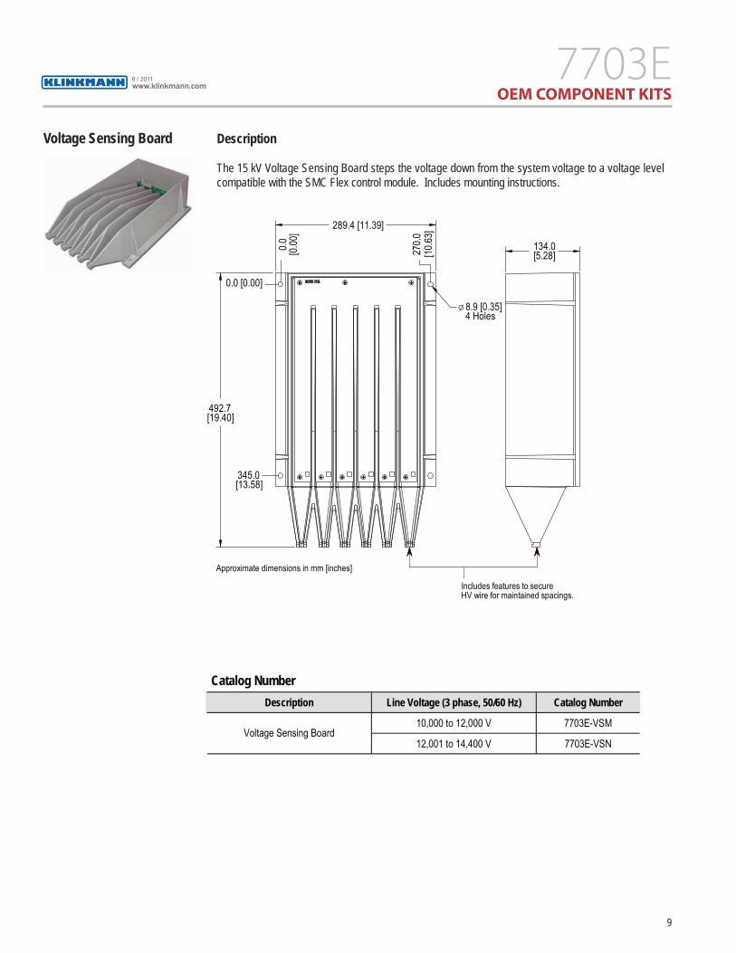
Voltage Sensing Board Description
The 15 kV Voltage Sensing Board steps the voltage down from the system voltage to a voltage level compatible with the SMC Flex control module. Includes mounting instructions.
Catalog Number Description Line Voltage (3 phase, 50/60 Hz) Catalog Number
10,000 to 12,000 V 7703E-VSM Voltage Sensing Board
12,001 to 14,400 V 7703E-VSN
Approximate dimensions in mm [inches]
289.4 [11.39]
0.0 [0.00
]
270.0
[10.63
]
0.0 [0.00]
134.0[5.28]
8.9 [0.35]4 Holes
345.0[13.58]
492.7[19.40]
Includes features to secureHV wire for maintained spacings.
www.klinkmann.com6 / 2011

10
Interface Board Description
Converts digital signals from the SMC Flex control module to drive the gate driver boards via fi ber optics. It also provides voltage, current and temperature feedback to the control module. Includes mounting instructions.
Note: Dimensions shown include mounting bracket assembly which is included with the interface board.
Interface Board and Mounting Brackets27.6
[1.09]
Approximate dimensions in mm [inches]
Front View
Mounting holes (4)7.14 mm [0.281 in.) dia.
Top mounting holes for SMC Flex Control Module
Bottom mounting holes for SMC Flex Control Module Side View
27.6[1.09]
.
256.2 [10.09]
241.3 [9.50]
241.3[9.50]
285.8[11.25]
SpecificationsControl Voltage 110/120 to 220/240 V – 50/60 Hz, 15 VA
Gate Drive Via Fiber Optics
SCR Overtemperature Via Fiber Optics
Catalog NumberInterface Board Catalog Number
110/120 to 220/240 V AC – 50/60 Hz 7703E-INTB
www.klinkmann.com6 / 2011

11
Fiber Optic Multiplexer DescriptionBoard Accepts fi ber optic gate drive signals from the interface board (7703E-INTB) and splits them into the
required fi ber optic gate drive signals for 10-15 kV.
4.0 [0.16] (5) MTG HOLES
118.4[4.66]
52.8[2.08]
210.0 [8.27]
201.4 [7.93]
100.7 [3.96]
127.0[5.00]
28.6[1.13]
Phase A Phase B Phase C
SpecificationsControl Voltage 110/120 to 220/240 V – 50/60 Hz, 30 VA
Gate Drive (In/Out) Via Fiber Optics
Catalog Number Fiber Optic Multiplexer Board Catalog Number
110/120 to 220/240 VAC – 50/60 Hz 7703E-MUXB
www.klinkmann.com6 / 2011

12
SMC Flex Control Module Description
The SMC Flex control module provides microprocessor controlled starting for standard three-phase, squirrel-cage induction motors. The SMC Flex control module provides the following modes of operation as standard:
• Soft Start – with selectable kickstart • Soft Stop
• Current Limit Start – with selectable kickstart• Linear Acceleration* – with selectable kickstart
• Linear Deceleration*• Dual Ramp – with selectable kickstart • Full Voltage• Preset Slow Speed
* requires motor tachometer
The SMC Flex control module provides motor protection, including overload, underload, stall, jam, etc., during starting and while the bypass contactor is energized.
Starting and Stopping Options
The following control option is available:
• Pump Control
www.klinkmann.com6 / 2011
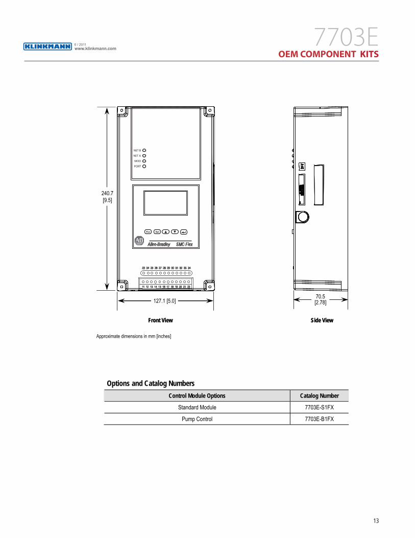
13
Options and Catalog Numbers Control Module Options Catalog Number
Standard Module 7703E-S1FX
Pump Control 7703E-B1FX
Front View Side View
240.7[9.5]
127.1 [5.0]70.5[2.78]
Approximate dimensions in mm [inches]
Front View Side View
240.7[9.5]
127.1 [5.0]70.5[2.78]
Approximate dimensions in mm [inches]
NET B
NET A
MOD
PORT
Allen-Bradley SMC Flex
Esc Sel
23 24 25 26 27 28 29 30 31 32 33 34
11 12 13 14 15 16 17 18 19 20 21 22
www.klinkmann.com6 / 2011

14
Fiber Optics Description
Fiber optic cables connect the interface board to gate driver boards mounted on power stacks. They are also used to connect thermistors in the power stacks to interface boards. Two lengths are available to aid the design and manufacture of a new controller, or to retrofi t into an existing enclosure. Includes mounting instructions.
SpecificationsNo. of Cables Voltage Range 2.5 m (8.2 ft) 5.0 m (16.4 ft)
12000 V 36 3613800 V 42 42
Options and Catalog Numbers Fiber Optic System Voltage Length of Cable Catalog Number
2.5 m (8.2 ft) 7703E-25FO30 12000 V 5.0 m (16.4 ft) 7703E-50FO30 2.5 m (8.2 ft) 7703E-25FO36 13800 V 5.0 m (16.4 ft) 7703E-50FO36
www.klinkmann.com6 / 2011

Gate Driver Test Power DescriptionSupply
The test power supply is used to provide power for the gate driver board during commissioning and/or troubleshooting. Includes operating instructions.
Options and Catalog Numbers Test Power Supply Options Catalog Number
120 V AC, 60 Hz 7703E-PSD Universal (requires power cord) 7703E-PSU
Specifications
Voltage Range 120 V AC – 60 Hz 110/220 V AC – 50/60 Hz
AC Power Cord North American (Cord supplied)
Universal (Cord supplied by OEM)
Publication 7703E-BR001A-EN-P – May 2011 Copyright © 2011 Rockwell Automation, Inc. All rights reserved. Printed in Canada.
Rockwell_Medium_Voltage_7703E_OneGear_Brochure_en_0611.pdf
Samaratel. +7 846 273 95 [email protected]
Yekaterinburgtel. +7 343 376 [email protected]
St. Petersburgtel. +7 812 327 [email protected]
Moscowtel. +7 495 641 [email protected]
Helsinkitel. +358 9 540 [email protected]
Vilniustel. +370 5 215 [email protected]
Rigatel. +371 6738 [email protected]
Мinsktel. +375 17 200 [email protected]
Tallinntel. +372 668 [email protected]
Кievtel. +38 044 495 33 [email protected]
www.klinkmann.com


