ONIX8 and ONIX10 Installation Guide T ABLE OF CONTENTS Introduction ......................................... 1 Install the Control Head ............................... 2 Install the Transducer................................. 4 Route the Cables .................................... 16 Connect the Transducer Cable ........................ 17 Install Accessories .................................. 17 Connect the Control Head Power Cable ................ 19 Test and Finish the Installation ....................... 20 Power On the Control Head ........................... 22 Setup Guide ........................................ 22 Set Up the Control Head .............................. 26 Manage Your Control Head ........................... 30 NMEA Input/Output .................................. 31 Specifications ...................................... 34 Maintenance ........................................ 38 Troubleshooting ..................................... 39 Side Imaging Transducer Mounting Template ........... 41 Contact Humminbird ................................ 42 532187-1_A
THANK YOU!Thank you for choosing Humminbird®, the #1 name in marine electronics. Humminbird has built its reputation by designing andmanufacturing top-quality, thoroughly reliable marine equipment. Your Humminbird is designed for trouble-free use in even the harshestmarine environment. In the unlikely event that your Humminbird does require repairs, we offer an exclusive Service Policy. For completedetails, see the separate warranty card included with your unit. We encourage you to read this operations manual carefully in order to getfull benefit from all the features and applications of your Humminbird product.
Contact Humminbird Customer Service at 1-800-633-1468 or visit our Web site at humminbird.com.
WARNING! This device should not be used as a navigational aid toprevent collision, grounding, boat damage, or personal injury. Whenthe boat is moving, water depth may change too quickly to allowtime for you to react. Always operate the boat at very slow speedsif you suspect shallow water or submerged objects.
WARNING! The electronic chart in your Humminbird unit is an aid tonavigation designed to facilitate the use of authorized governmentcharts, not to replace them. Only official government charts andnotices to mariners contain all of the current information neededfor the safety of navigation, and the captain is responsible for theirprudent use.
WARNING! Compass Safe Distance: The control head must beinstalled at least 4 feet (1.2 meters) from the compass or othermagnetic equipment on the boat. Also, see your compassinstallation guide for details.
WARNING! Humminbird is not responsible for the loss of data files(waypoints, routes, tracks, groups, recordings, etc.) that may occurdue to direct or indirect damage to the unit’s hardware or software.It is important to back up your control head’s data files periodically.Data files should also be saved to your PC before restoring the unit’sdefaults or updating the software. See your Humminbird onlineaccount at humminbird.com and the operations manual on yourHumminbird Manual CD for details.
WARNING! Disassembly and repair of this electronic unit shouldonly be performed by authorized service personnel. Anymodification of the serial number or attempt to repair the originalequipment or accessories by unauthorized individuals will void thewarranty.
WARNING! This product contains chemicals known to the State ofCalifornia to cause cancer and/or reproductive harm.
WARNING! Do not travel at high speed with the unit cover installed.Remove the unit cover before traveling at speeds above 20 mph.
NOTE: Some features discussed in this manual require a separatepurchase, and some features are only available on internationalmodels. Every effort has been made to clearly identify thosefeatures. Please read the manual carefully in order to understandthe full capabilities of your model.
NOTE: The illustrations in this manual may not look the same asyour product, but your unit will function in the same way.
NOTE: To purchase accessories or any additional equipment foryour control head configuration, go to humminbird.com or contactCustomer Service at 1-800-633-1468.
NOTE: The procedures and features described in this manual aresubject to change without notice. This manual was written inEnglish and may have been translated to another language.Humminbird is not responsible for incorrect translations ordiscrepancies between documents.
Environmental Compliance Statement: It is the intention of JohnsonOutdoors Marine Electronics, Inc. to be a responsible corporate citizen,operating in compliance with known and applicable environmentalregulations, and a good neighbor in the communities where we make orsell our products.
WEEE Directive: EU Directive 2002/96/EC “Waste of Electrical andElectronic Equipment Directive (WEEE)” impacts most distributors, sellers,and manufacturers of consumer electronics in the European Union. TheWEEE Directive requires the producer of consumer electronics to takeresponsibility for the management of waste from their products to achieveenvironmentally responsible disposal during the product life cycle.
WEEE compliance may not be required in your location for electrical &electronic equipment (EEE), nor may it be required for EEE designed andintended as fixed or temporary installation in transportation vehicles suchas automobiles, aircraft, and boats. In some European Union memberstates, these vehicles are considered outside of the scope of the Directive,and EEE for those applications can be considered excluded from the WEEEDirective requirement.
This symbol (WEEE wheelie bin) on product indicates the productmust not be disposed of with other household refuse. It must bedisposed of and collected for recycling and recovery of waste EEE.Johnson Outdoors Marine Electronics, Inc. will mark all EEE
products in accordance with the WEEE Directive. It is our goal to comply inthe collection, treatment, recovery, and environmentally sound disposalof those products; however, these requirements do vary within EuropeanUnion member states. For more information about where you shoulddispose of your waste equipment for recycling and recovery and/or yourEuropean Union member state requirements, please contact your dealeror distributor from which your product was purchased.
ROHS Statement: Product designed and intended as a fixed installationor part of a system in a vessel may be considered beyond the scope ofDirective 2002/95/EC of the European Parliament and of the Council of 27January 2003 on the restriction of the use of certain hazardoussubstances in electrical and electronic equipment.
ATTENTION INTERNATIONAL CUSTOMERS: Products sold in the U.S.are not intended for use in the international market. Humminbirdinternational units provide international features and are designedto meet country and regional regulations. Languages, maps, timezones, units of measurement, and warranty are examples offeatures that are customized for Humminbird international unitspurchased through our authorized international distributors.
To obtain a list of authorized international distributors, please visitour Web site at humminbird.com or contact Customer Service at(334) 687-6613.
360 Imaging™, Cross Touch™, Down Imaging®, DualBeam PLUS™, Humminbird®, i-Pilot®, ONIX™, and Side Imaging® are trademarked by or registered trademarks ofJohnson Outdoors Marine Electronics, Inc.
Adobe, Acrobat, Adobe PDF, and Reader are either registered trademarks or trademarks of Adobe Systems Incorporated in the United States and/or other countries.
Navionics® Gold and Navionics® Classic Charts are trademarked by or registered trademarks of Navionics®.
C-MAP® by Jeppesen is a registered trademark of Jeppesen Marine, Inc.
NMEA 2000® is a registered trademark of the National Marine Electronics Association.
INTRODUCTIONThis manual will guide you through the following installation requirements:
• Installing the Control Head
• Installing the Transducer
• Connecting Cables to the Control Head
• Connecting the Control Head to Power
• Powering On the Control Head
• Configuring the Control Head and Basic System Setup
PREPARATIONBefore you start the installation, please take a moment to familiarize yourself with the partslist and supplies list. We also encourage you to read the instructions beforehand so that youmay understand the installation requirements.
NOTE: Product supplies and features are subject to change without notice.
PartsYour ONIX includes the following items:
ONIX control head with cover
gimbal mounting bracket with gimbal mounting hardware
(2) gimbal knobs
(2) urethane washers
(4) flat washers
(4) 1" - #10 wood screws
(4) 1" - split ring cable grommets
(1) transducer with transducer mounting hardware
power cable
SuppliesIn addition to the parts supplied with your installation kit, you will need the following items:
• powered drill with various drill bits
• various hand tools, including
a socket wrench or flat blade screwdriver
ruler, straightedge, or measuring tape
level
12" plumb line (weighted string or monofilament line)
• marker or pencil
• safety glasses
• dust mask
• marine-grade silicone sealant
• dielectric grease (optional)
I
H
G
F
E
D
C
B
A
A
B
F
D
E
C
G
H
I
OR OR
DualBeam PLUStransducers
Side Imagingtransducer
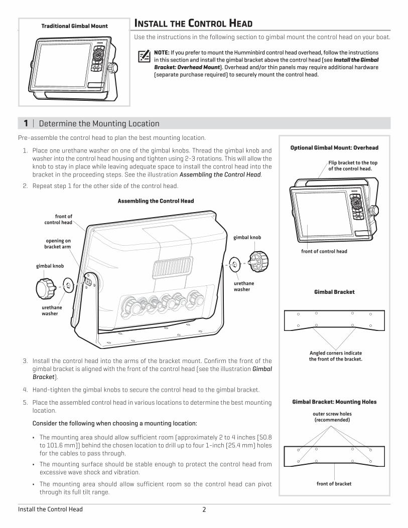
INSTALL THE CONTROL HEADUse the instructions in the following section to gimbal mount the control head on your boat.
NOTE: If you prefer to mount the Humminbird control head overhead, follow the instructionsin this section and install the gimbal bracket above the control head (see Install the GimbalBracket: Overhead Mount). Overhead and/or thin panels may require additional hardware(separate purchase required) to securely mount the control head.
1 | Determine the Mounting Location
Pre-assemble the control head to plan the best mounting location.
1. Place one urethane washer on one of the gimbal knobs. Thread the gimbal knob andwasher into the control head housing and tighten using 2-3 rotations. This will allow theknob to stay in place while leaving adequate space to install the control head into thebracket in the proceeding steps. See the illustration Assembling the Control Head.
2. Repeat step 1 for the other side of the control head.
3. Install the control head into the arms of the bracket mount. Confirm the front of thegimbal bracket is aligned with the front of the control head (see the illustration GimbalBracket).
4. Hand-tighten the gimbal knobs to secure the control head to the gimbal bracket.
5. Place the assembled control head in various locations to determine the best mountinglocation.
Consider the following when choosing a mounting location:
• The mounting area should allow sufficient room (approximately 2 to 4 inches [50.8to 101.6 mm]) behind the chosen location to drill up to four 1-inch (25.4 mm) holesfor the cables to pass through.
• The mounting surface should be stable enough to protect the control head fromexcessive wave shock and vibration.
• The mounting area should allow sufficient room so the control head can pivotthrough its full tilt range.
urethanewasher
urethanewasher
front ofcontrol head
opening onbracket arm
gimbal knob
gimbal knob
Assembling the Control Head
Gimbal Bracket
Angled corners indicatethe front of the bracket.
Gimbal Bracket: Mounting Holes
front of bracket
outer screw holes(recommended)
Optional Gimbal Mount: Overhead
Flip bracket to the topof the control head.
front of control head
Traditional Gimbal Mount
2Install the Control Head
• The mounting location should allow for visibility duringoperation, as well as easy installation and removal.
• You must have access, either above or below themounting surface, to pass the cables through to thecontrol head.
6. Test route the appropriate cables (power, accessory, etc.) tothe control head mounting location. If the cables are tooshort for your application, extension cables are available.Contact Customer Service for information.
2 | Drill the Mounting Holes1. Loosen the gimbal knobs and remove the control head from
the gimbal bracket.
2. Place the gimbal bracket in the chosen position on themounting surface and mark the four outer screw locationsusing a pencil or center punch (see the illustration GimbalBracket: Mounting Holes). Confirm the front of the bracket isfacing forward.
NOTE: The outer mounting holes are recommended.You may use the interior mounting holes if necessary.
3. Set the gimbal bracket aside. Select an appropriately sizeddrill bit for the #10 wood screws and drill four pilot screwholes.
NOTE: When drilling holes in fiberglass, start with asmaller bit and use progressively larger drill bits toreduce the chance of chipping the outer coating.
4. Mark and drill a 1-inch (25.4 mm) diameter hole that willallow you to run the cables close to the mounting bracket.This hole should be centered approximately 2 to 4 inches(50.8 to 101.6 mm) from the back of the control head.
NOTE: Your installation may require additional cableholes. Mark and drill up to four holes according to theinstructions in step 4.
5. Insert the plastic cable grommets (included) to smooth thehole edges and prevent damage to the cables.
3 | Install the Gimbal BracketRefer to the section that applies to your installation and performthe procedures to install the gimbal bracket.
Traditional Mount1. Place the bracket on the mounting surface aligned with the
drilled holes and fill the holes with marine-grade siliconesealant.
2. Place one flat washer on each wood screw and install thewood screws into the four mounting holes (see theillustration Installing the Gimbal Bracket).
3. After all four screws are in place, tighten each screw untilsecure.
4. Place the control head back onto the gimbal bracket (seeDetermine the Mounting Location for details). Adjust thecontrol head viewing angle as needed and tighten the gimbalknobs until the assembly is secured.
Overhead Mount1. Place the bracket on the mounting surface aligned with the
drilled holes. Fill one hole with marine-grade siliconesealant.
2. Place one flat washer on a wood screw and install the woodscrew into the hole (see the illustration Installing the GimbalBracket). Repeat for the remaining three holes.
3. Tighten each screw until it is secure.
4. Place the control head back onto the gimbal bracket (seeDetermine the Mounting Location for details). Adjust thecontrol head viewing angle as needed and tighten the gimbalknobs until the assembly is secured.
NOTE: Overhead and/or thin panels may requireadditional hardware (separate purchase required) tosecurely mount the control head.
Installing the Gimbal Bracket
wood screws
flat washers
3 Install the Control Head
INSTALL THE TRANSDUCERReview the transducer installation options and the transducer mounting requirements in the following sections. Then proceed to theinstallation section for your transducer type as follows:
• DualBeam PLUS Transducer
• Side Imaging Transducer
NOTE: If the included transducer will not work for your application, you can exchange it, NEW and UNASSEMBLED, with the transducermounting hardware included, for a transducer appropriate for your application. This offer applies to the DualBeam PLUS transducer only.Visit humminbird.com for more information or call Customer Service at 1-800-633-1468.
TRANSDUCER INSTALLATION OPTIONSYour ONIX control head includes either a DualBeam PLUS transducer or a Side Imaging transducer. Depending on your transducer type,there are different options available for mounting the transducer on the boat. Review the transducer installation options below.
Transom Transducer InstallationAvailable for the DualBeam PLUS transducer and the Side Imaging transducer.
Your transducer includes the transom mounting hardware. See Transom TransducerInstallation for additional information.
In-Hull Transducer InstallationAvailable for the DualBeam PLUS transducer only.
In-hull mounting generally produces good results in single thickness, fiberglass-hulled boats.See DualBeam PLUS Inside the Hull Installation for installation instructions.
Humminbird cannot guarantee depth performance when transmitting and receiving throughthe hull of the boat, since some signal loss occurs. The amount of loss depends on hullconstruction and thickness, as well as the installation position and process.
NOTE: This installation requires slow-cure two-part epoxy. Do not use silicone or any othersoft adhesive to install the transducer, as this material reduces the sensitivity of the unit. Donot use five-minute epoxy, as it has a tendency to cure before all the air bubbles can bepurged, thus reducing signal strength.
NOTE: The integral temperature probe will not work with in-hull mounting, so you may wantto consider purchasing a Temperature/Speed accessory, a Temp Sensor, or obtaining adifferent transducer.
NOTE: In-hull mounting requires an installed and operational control head.
Trolling Motor Transducer InstallationAvailable for the DualBeam PLUS transducer and the Side Imaging transducer.
You can purchase a Trolling Motor Adapter kit that will allow you to mount the transducer onthe trolling motor. If you already have a trolling motor bracket, refer to the separate installationinstructions that are included with the bracket.
NOTE: Visit our Web site at humminbird.com for more information, or call Customer Serviceat 1-800-633-1468 for details and pricing.
In-Hull Transducer Installation
Trolling Motor Transducer Installation
Transom Transducer Installation
4Install the Transducer
TRANSOM TRANSDUCER INSTALLATIONYour ONIX control head includes transom mounting hardware for your DualBeam PLUS orSide Imaging transducer. Review the mounting requirements in this section, and then proceedto the section for your transducer type to begin the installation.
NOTE: Due to the wide variety of hulls, only general instructions are presented in thisinstallation guide. Each boat hull represents a unique set of requirements that should beevaluated prior to installation. It is important to read the instructions completely andunderstand the mounting guidelines before beginning installation.
INSTALLATION OVERVIEWThe transom mount installation provides the following:
• Least loss of signal since the transducer is mounted outside the hull.
• Allows adjustment of both running angle and depth after the transducer is mounted, which enables you to tune the installationfor best results.
• The mounting hardware is designed to pivot the transducer body out of the way should the boat strike debris in the water, or whentrailering.
TRANSOM TRANSDUCER MOUNTING REQUIREMENTSYou must first determine the best location on the transom to install the DualBeam PLUS or Side Imaging transducer. Review thefollowing information to help you identify the best mounting location.
TurbulenceIt is very important to locate the transducer in an area that is relatively free of turbulentwater. Consider the following to find the best location with the least amount of turbulence:
Turbulence: As the boat moves through the water, turbulence is generated by the weight ofthe boat and the thrust of the propeller(s) - either clockwise or counter-clockwise. This turbulent water is normally confined to areas immediately aft ofribs, strakes, or rows of rivets on the bottom of the boat, and in the immediatearea of the propeller(s).
Propellers: Clockwise propellers create more turbulence on the port side. On outboard orinboard/outboard boats, it may be best to locate the transducer at least 15" tothe side of the propeller(s). The Side Imaging transducer has additionalmounting requirements. See the section Side Imaging Transducer MountingRequirements.
If the transom is behind the propeller(s), it may be impossible to find an areaclear from turbulence, and a different mounting technique or transducer typeshould be considered.
Find a turbulence-free location that is not in line with trailer bunks or rollers.
rivets transom
strakeshull
Areas of Possible Turbulence
step rib
Stepped Hull
Installing the Transom Mount Transducer
5 Transom Transducer Installation
Observation: The best way to locate turbulence-free water is to view the transom while the boat is moving. This method isrecommended if maximum high-speed operation is a high priority. If this is not possible, select a location on thetransom where the hull forward of this location is smooth, flat, and free of protrusions or ribs.
Boat Characteristics
Stepped Hulls: On boats with stepped hulls, it may be possible to mount the transducer on the step. Do not mount the transducer onthe transom behind a step to avoid popping the transducer out of the water at higher speeds. The transducer mustremain in the water for the control head to maintain the sonar signal.
Trailering: If you plan to trailer your boat, do not mount the transducer too close to trailer bunks or rollers to avoid moving ordamaging the transducer during loading and unloading of the boat.
High-Speed Operation
DualBeam PLUS TransducerTraveling over 65 mph with the transducer in the water is not recommended for the 200/50 kHz DualBeam PLUS transom mounttransducer (XNT 14 74 T), as damage might occur. If high-speed operation is critical, you may want to consider using an inside the hulltransducer instead of this transom mount transducer (see DualBeam PLUS Inside the Hull Installation).
Side Imaging TransducerSide Imaging sonar is best performed at boat speeds from 2 to 6 mph, and is not recommended for high-speed operation as gapsbetween strips of information can appear. However, the transducer can support traditional 2D sonar and Down Imaging sonar at higherspeeds (up to 65 mph).
NOTE: The Side Imaging transducer has additional mounting requirements. See the section Side Imaging Transducer MountingRequirements.
NOTE: If you require a high-speed application (above 65 mph) and cannot find a transom mount location that will work for yourboat hull, a different mounting technique or transducer type should be considered. See the FAQ (Frequently Asked Questions)section of our Web site at humminbird.com or call Customer Service at 1-800-633-1468.
Deadrise
DualBeam PLUS TransducerThe hydrodynamic shape of your transducer allows the beam elements to point straight downwithout deadrise adjustment.
Side Imaging TransducerIn order for the side beams to be displayed accurately, the transducer must be mounted parallelwith the waterline. This positioning allows the beam elements to point straight down withoutdeadrise adjustment.
Deadrise
deadrise angle
6Transom Transducer Installation
INSTALL THE DUALBEAM PLUS TRANSDUCERUse the procedures in the following sections to install the DualBeam PLUS transducer onyour boat. Your installation choices are as follows:
• Transom Mount
• Inside the Hull Mount
NOTE: Your transducer might not look exactly like the illustrations in this guide, but it willmount in the same way.
DUALBEAM PLUS TRANSOM MOUNT INSTALLATION
1 | Prepare the Mounting LocationIn this procedure, you will determine the mounting location and drill two mounting holes,using the transducer mounting bracket as a guide.
1. Confirm you have read the transducer mounting requirements under TransomTransducer Mounting Requirements.
2. Make sure that the boat is level on the trailer, both from port to starboard and frombow to stern, by placing your level on the deck of the boat, first in one direction, then inthe other.
3. Hold the mounting bracket against the transom of the boat in the location you haveselected. Align the bracket horizontally using the level. Make sure that the lower cornerof the bracket does not protrude past the bottom of the hull, and there is at least 1/4"clearance between the bottom of the bracket and the bottom of the transom forfiberglass boats, and 1/8" clearance for aluminum boats.
NOTE: If you have a flat-bottomed aluminum boat, some additional adjustment may beneeded to accommodate the rivets on the bottom of the boat (in other words, the gapmay need to be a little smaller than 1/8"). This will help you to avoid excessive turbulenceat high speeds.
NOTE: If your propeller moves clockwise as the boat moves forward (as you're facing thestern of the boat from behind), mount the transducer on the starboard side, and alignthe bottom right corner of the mounting bracket with the bottom of the boat. If yourpropeller moves counterclockwise as the boat moves forward (as you're facing the sternof the boat from behind), mount the transducer on the port side, and align the bottomleft corner of the mounting bracket with the bottom of the boat.
4. Continue to hold the bracket on the transom of the boat, and use a pencil or marker tomark where to drill the two mounting holes. Mark the drill holes near the top of each slot,making sure that your mark is centered in the slot, as shown in the illustration.
NOTE: The third hole should not be drilled until the angle and height of the transducer isfinalized, which you will not do until a later procedure.
5. Make sure that the drill bit is perpendicular to the actual surface of the transom, NOTparallel to the ground, before you drill. Using a 5/32" bit, drill the two holes only to adepth of approximately 1".
NOTE: On fiberglass hulls, it is best to use progressively larger drill bits to reduce thechance of chipping or flaking the outer coating.
Using the Mounting Bracketto Mark the Initial Drill Holes
DualBeam PLUS Transducers
200/83 kHz 200/50 kHz
7 Install the DualBeam PLUS Transducer
2 | Assemble the Transducer and Initial MountingIn this procedure, you will assemble the transducer using the hardware provided, then mount it and make adjustments to its positionwithout locking it in place.
NOTE: You will initially assemble the transducer and the pivot arm by matching the two ratchets to a numbered position on thetransducer knuckle. Further adjustments may be necessary.
Determine Your Transom Angle1a. If you already know your transom angle, refer to the chart below for the initial position to use to set the ratchets. If your transom
is angled at 14 degrees (a common transom angle for many boats) use position 1 for the ratchets. In either case, go to step 2.
or...
1b. If you do not know your transom angle, measure it using a plumb line (weighted nylon stringor monofilament line) exactly 12 inches long. Hold the top of the plumb line against the topof the transom with your finger, and wait until the line hangs straight down. Using a ruler,measure the distance from the bottom of the plumb line to the back of the transom, thenuse the chart. Refer to the illustration, Measuring the Transom Angle, for more information.
NOTE: It is important to take your measurement in the location shown in the Measuring theTransom Angle illustration, from exactly 12 inches down from the top of the transom.
Assemble the Transducer2. Place the two ratchets, one on either side of the transducer knuckle, so that the beads on
each ratchet line up with the desired position number on the knuckle. If you are setting theratchets at position 1, the beads on each ratchet will line up with the rib on the transducerknuckle to form one continuous line on the assembly.
NOTE: The ratchets are keyed. Make sure that the square teeth on each ratchet face the squareteeth on the transducer knuckle, and the triangular teeth face outward.
3. Hold the ratchets on the transducer knuckle with one hand and fit the pivot arm over themuntil it snaps into place with the other hand. Refer to the illustrations below.
knuckle
Transducer Knuckle Positions
beads
ratchet
rib atposition 1
Ratchets Placed in Position 1bead
ratchet
rib
Ratchets Placed in Position 2 Fitting the MountingBracket Over the Ratchet
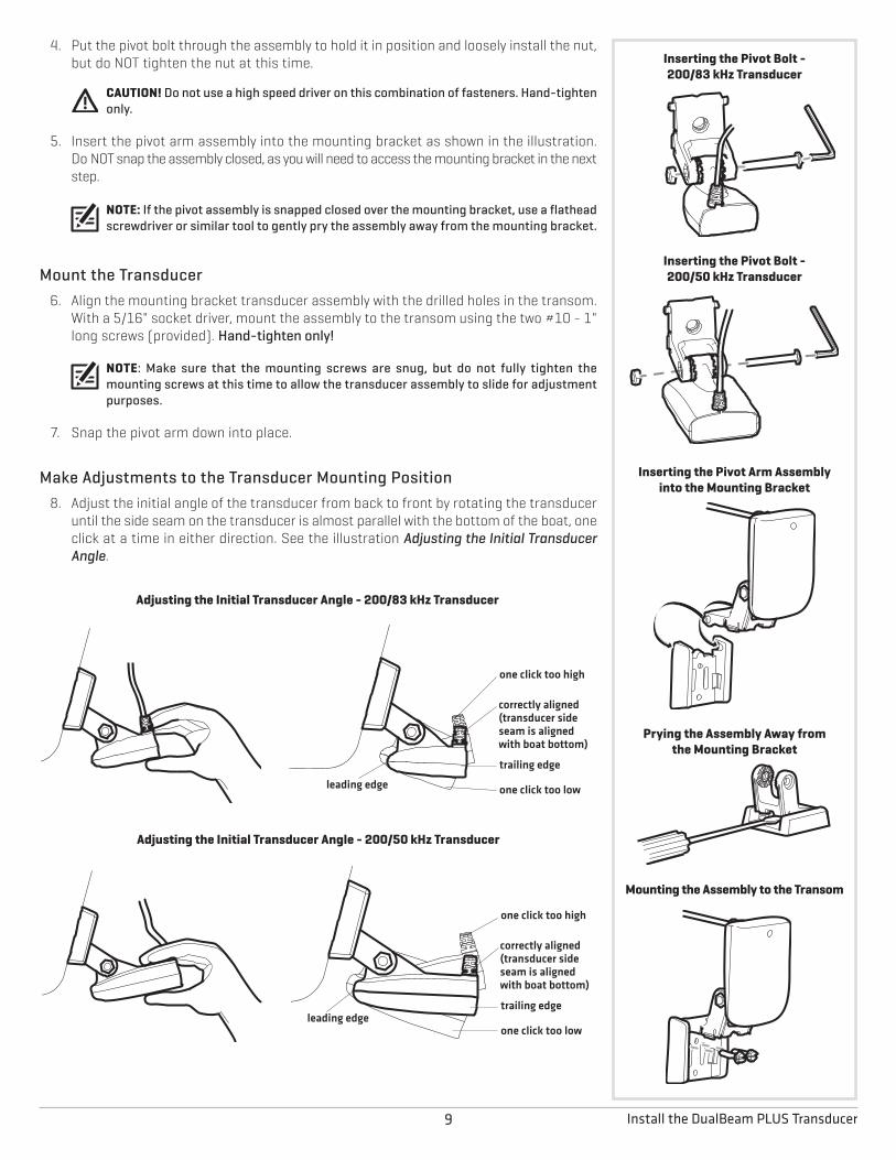
4. Put the pivot bolt through the assembly to hold it in position and loosely install the nut,but do NOT tighten the nut at this time.
CAUTION! Do not use a high speed driver on this combination of fasteners. Hand-tightenonly.
5. Insert the pivot arm assembly into the mounting bracket as shown in the illustration.Do NOT snap the assembly closed, as you will need to access the mounting bracket in the nextstep.
NOTE: If the pivot assembly is snapped closed over the mounting bracket, use a flatheadscrewdriver or similar tool to gently pry the assembly away from the mounting bracket.
Mount the Transducer6. Align the mounting bracket transducer assembly with the drilled holes in the transom.
With a 5/16" socket driver, mount the assembly to the transom using the two #10 - 1"long screws (provided). Hand-tighten only!
NOTE: Make sure that the mounting screws are snug, but do not fully tighten themounting screws at this time to allow the transducer assembly to slide for adjustmentpurposes.
7. Snap the pivot arm down into place.
Make Adjustments to the Transducer Mounting Position8. Adjust the initial angle of the transducer from back to front by rotating the transducer
until the side seam on the transducer is almost parallel with the bottom of the boat, oneclick at a time in either direction. See the illustration Adjusting the Initial TransducerAngle.
Adjusting the Initial Transducer Angle - 200/50 kHz Transducer
one click too high
correctly aligned(transducer sideseam is alignedwith boat bottom)
trailing edge
one click too lowleading edge
Adjusting the Initial Transducer Angle - 200/83 kHz Transducer
one click too high
correctly aligned(transducer sideseam is alignedwith boat bottom)
trailing edge
one click too lowleading edge
Inserting the Pivot Bolt -200/50 kHz Transducer
Prying the Assembly Away fromthe Mounting Bracket
Inserting the Pivot Arm Assemblyinto the Mounting Bracket
Mounting the Assembly to the Transom
Inserting the Pivot Bolt -200/83 kHz Transducer
9. Adjust the transducer assembly vertically, until the seam on the leading edge of thetransducer (the edge closest to the transom of the boat) is level and just slightlybelow the hull.
NOTE: The transducer has a natural downward slant of 4 to 5 degrees from leading edge(closest to the boat transom) to trailing edge (farthest away from the boat). Looking atthe back of the transducer, the seam should be slightly below the bottom of the hull.
10. Continue to adjust the transducer assembly until the bracket is also level from port tostarboard (horizontally level as you look at the transducer from behind the boat).
11. Mark the correct position on the transom by tracing the silhouette of the transducermounting bracket with a pencil or marker.
12. Tighten the pivot bolt, using the pivot screw and nut to lock the assembly. Hand-tightenonly!
CAUTION! Do not use a high speed driver on this combination of fasteners. Hand-tightenonly.
13. Snap open the assembly and hand-tighten the two mounting screws, then snap theassembly closed.
NOTE: You will drill the third mounting hole and finalize the installation after you routethe cable and test and finish the installation in the following procedures.
Proceed to the section Route the Cables.
DUALBEAM PLUS INSIDE THE HULL INSTALLATIONIn-hull mounting generally produces good results in single thickness, fiberglass-hulled boats. Humminbird cannot guarantee depthperformance when transmitting and receiving through the hull of the boat, since some signal loss occurs. The amount of loss dependson hull construction and thickness, as well as the installation position and process.
NOTE: The integral temperature probe will not work with in-hull mounting, so you may want to consider purchasing aTemperature/Speed accessory, a Temp Sensor, or obtaining a different transducer.
NOTE: In-hull mounting requires an installed and operational control head.
Level
Level
Leveling the MountingAssembly Horizontally
Adjusting the TransducerMounting Position
seam alignedwith boat hull
This installation requires slow-cure two-part epoxy. Do not use silicone or any other soft adhesive to install the transducer, as thismaterial reduces the sensitivity of the unit. Do not use five-minute epoxy, as it has a tendency to cure before all the air bubblescan be purged, thus reducing signal strength.
10Install the DualBeam PLUS Transducer
1 | Determine the Transducer Mounting LocationDecide where to install the transducer on the inside of the hull. Consider the following to findthe best location:
• Observe the outside of the boat hull to find the areas that are mostly free from turbulentwater. Avoid ribs, strakes, and other protrusions, as these create turbulence (see Areasof Possible Turbulence).
• As a general rule, the faster the boat can travel, the further aft and closer to the centerlineof the hull the transducer has to be located in order to remain in contact with the waterat high speeds (see Preferred Mounting Area).
2 | Trial InstallationYou will not be able to adjust the mounting after an inside the hull transducer is installed. It isbest, therefore, to perform a trial installation first that includes running the boat at variousspeeds, in order to determine the best mounting area before permanently mounting thetransducer.
1. Plug the transducer into the control head, then power up the control head. If the unitdoes not power-up, confirm that the cable connectors are properly connected and thatpower is available.
2. Setup Guide: See the section Setup Guide for initial start up instructions. You mustcomplete the steps indicated in the Setup Guide before starting normal operation.
NOTE: After completing the Setup Guide, the control head will automatically enter normaloperation.
3. Press the HOME key .
4. Select a sonar view from the Favorites bar to display on-screen.
NOTE: See your control head operations manual for more information about selectingviews.
5. View the sonar signal at its best by holding the transducer over the side, immersed in thewater, so that it is pointing straight down over a known flat bottom. Use the display tobenchmark against the sonar signal that will be detected once the transducer is placedin the hull.
6. Place the transducer body face down at the identified mounting location inside the hull,with the pointed end towards the bow (see In-Hull Transducer Installation).
7. Fill the hull with enough water to submerge the transducer body. Use a sand-filled bag orother heavy object to hold the transducer in position. The transducer cannot transmitthrough air, and the water purges any air from between the transducer and the hull, andfills any voids in the coarse fiberglass surface.
8. View the sonar signal on the display and compare against what was observed in Step 5,making sure that the boat is in the same location as it was during your observations inStep 5. If the results are comparable, move on to Step 9. Otherwise, locate a new positionin the hull and repeat Steps 6 through 8.
9. Run the boat at various speeds and water depths while observing the screen on thecontrol head. If depth performance is required, test the transducer in water at the desireddepth. If the performance is acceptable, move on to Step 10. If the performance is notacceptable, repeat Steps 6 through 9.
10. Once you have determined the best mounting location using the above steps, mark theposition of the transducer.
3 | Route the Cable1. Once the mounting location is determined and you have marked the position of the
transducer, route the cable from the transducer to the control head.
4 | Permanently Mount the Transducer1. Make sure the position of the transducer is marked.
2. You may have to disconnect the cable to the control head and reconnect it at the end ofthis procedure.
3. Remove the water from inside the hull and thoroughly dry the mounting surface. If thesurface is excessively rough, it may be necessary to sand the area to provide a smoothmounting surface.
4. Mix an ample quantity of two-part slow cure epoxy slowly and thoroughly. Avoid trappingair bubbles.
5. Coat the face of the transducer and the inside of the hull with epoxy (see In-HullTransducer Installation and Applying Epoxy to the Transducer).
6. Press the transducer into place with a slight twisting motion to purge any trapped airfrom underneath, keeping the pointed end of the transducer body pointed forward,towards the bow (see Installing the Transducer).
NOTE: Proper operation requires the pointed end of the transducer body to face towardsthe bow.
7. Weight the transducer so that it will not move while the epoxy is curing.
NOTE: When the epoxy cures, no water is necessary inside the hull.
NOTE: Neither water, spilled gasoline, nor oil will affect the performance of thetransducer.
Proceed to the section Connect the Transducer Cable.
Applying Epoxy to the200/50 kHz Transducer
Installing the 200/50 kHz Transducer
Applying Epoxy to the200/83 kHz Transducer
Installing the 200/83 kHz Transducer
12Install the DualBeam PLUS Transducer
13 Install the Side Imaging Transducer
INSTALL THE SIDE IMAGING TRANSDUCERUse the procedures in this section to install the Side Imaging transducer on your boat. Thetransducer mounting template is provided at the end of this manual (see Side ImagingTransducer Mounting Template).
NOTE: See the Transom Transducer Mounting Requirements before beginning theinstallation.
SIDE IMAGING TRANSDUCER MOUNTING REQUIREMENTS
Side Imaging Transducer
Side Imaging RequirementsIn addition to the requirements shown in the Transom TransducerMounting Requirements section, the Side Imaging transducer hassome special requirements because of its side viewingcapabilities:
• The Side Imaging transducer must NOT have anythingobstructing the ‘view’ of the side looking beams. Forexample, nothing can be in the line of sight of these beams(not a hull, motor, additional transducer, etc.). See theillustrations below.
NOTE: You may need to tilt the motor up and out ofthe way when using the side looking beams.
Multiple Transducer Installation (optional)If you have installed or are planning to install a second transducerin addition to this Side Imaging transducer, you must determinewhich transducer will be used as the primary source for traditional2D sonar when operating the boat at high speeds (up to 65 mph).There are special mounting requirements for the Side Imagingtransducer depending on if it will be in the water or out of the waterduring high-speed operation.
Primary Source - Side Imaging TransducerIf you plan to use the Side Imaging transducer as the primarysource for traditional 2D sonar and Down Imaging sonar duringhigh-speed operation (up to 65 mph), mount the transducer atleast 15" from the center of the engine with an unobstructed viewon both sides of the transducer (see Side Imaging Requirementsand the illustration Transducer Mount Position: UnobstructedView).
Primary Source - Secondary TransducerIf you plan to use a second transducer as the primary source fortraditional 2D sonar only during high-speed operation (up to 65mph), mount the Side Imaging transducer where it will not be indirect water flow. For this installation, you may install thetransducer less than 15" from the center of the engine. Reviewthe following mounting alternatives:
• The Side Imaging transducer can be mounted on or near thecenterline of the boat and higher on the transom to preventdirect contact with water flow under the boat at high speeds.Confirm that the transducer is low enough on the transom tobe submerged in the water at low speeds. It should not comeinto contact with the motor when it is raised or lowered.
NOTE: Mounting the Side Imaging transducer higheron the transom should not create turbulence thataffects the engine’s water intakes. Contact yourdealer to verify your individual boat setup.
• The Side Imaging transducer can be mounted to the jackplate. Contact your dealer for more information about thebrands of jack plates that will accommodate this type ofinstallation.
NOTE: A Y-cable or transducer switch may be requiredto connect the Side Imaging transducer to the secondtransducer. The Y-cable and transducer switch requireseparate purchases.
Transducer Mount Position: Unobstructed ViewThe jack plate gives the transducer safe distance from the motorand turbulence. The Side Imaging beams have a clear view side-to-side.
Transducer Mount Position: Obstructed ViewThe transducer is too close tomotor turbulence, and the Side Imaging viewis blocked by the motor. The view cannot extend from side-to-side.
14Install the Side Imaging Transducer
Deadrise• In order for the side beams to be displayed accurately, the transducer must be mounted
parallel with the waterline. This positioning allows the beam elements to point straightdown without deadrise adjustment (see the illustration Deadrise).
NOTE: Rough seas, high speed, and air bubbles can also affect the reading of the SideImaging transducer.
1 | Mount the Transducer BracketIn this procedure you will mount the bracket, using the mounting template provided as aguide. This template allows you to mark where the mounting holes should be drilled. SeeSide Imaging Transducer Mounting Template at the end of this manual.
1. Confirm you have read the transducer mounting requirements under TransomTransducer Mounting Requirements and Side Imaging Transducer MountingRequirements.
2. Cut out the transducer mounting template from the back of this manual (see SideImaging Transducer Mounting Template). Match the mounting bracket screw slots tothe template screw slots.
3. Hold the template on the transom of the boat in the location you have selected. Alignthe template vertically, matching the lower edge of the transom with the bottom cornerof the template.
NOTE: If your propeller moves clockwise as the boat moves forward (as you're facingthe stern of the boat from behind), mount the transducer on the starboard side, anduse the bottom left corner of the template. If your propeller moves counter-clockwiseas the boat moves forward (as you're facing the stern of the boat from behind), mountthe transducer on the port side, and use the bottom right corner of the template.
4. Continue to hold the template on the transom of the boat, and use a pencil or punchto mark where to drill the three mounting holes shown on the template.
5. Using a 5/32" bit, drill the three holes only to a depth of approximately 1".
NOTE: On fiberglass hulls, it is best to use progressively larger drill bits to reduce thechance of chipping or flaking the outer coating.
6. Use a marine-grade silicone sealant to fill the drilled holes, especially if the holespenetrated the transom wall.
7. Align the metal mounting bracket with the mounting holes. The center slot of yourmounting bracket should be above the two outer slots. Insert the three 1" flat headwood screws into the drilled holes, but do not completely tighten.
NOTE: The mounting bracket and all other hardware supplied is top quality stainlesssteel for maximum strength and corrosion protection.
2 | Assemble the TransducerIn this procedure you will attach the pivot to the transducer using the hardware provided.
1. Attach the pivot to the transducer body as shown in the illustrations using the squarenuts, toothed washers, and two 1/4–20 x 5/8" machine screws. The square nuts will beprevented from rotating by the pocket in the back of the pivot. The toothed washersmust fit on the inside of the transducer ears, between the pivot and the ears.
NOTE: An Allen wrench is provided which fits all of the 1/4–20 screws, but do not fullytighten the screws at this time.
Attaching the Bracket
Inserting the Square Nuts
squarenuts
pivottoothedwasher
transducerear
Attaching the Pivot
machinescrew
Deadrise
deadrise angle
15 Install the Side Imaging Transducer
3 | Attach the Transducer to the Bracket1. Slide the assembled transducer into the metal bracket from the bottom, aligning the
large hole at the top of the bracket with the hole in the pivot.
2. Insert the headed pin through the pivot holes in the bracket and pivot. The headed pincan be inserted from either side of the bracket.
3. Place the nylon washer over the opposite end of the headed pin. Place the stainlesswasher over the 1/4–20 x 5/8" screw threads, then insert into the opposite end of theheaded pin and finger tighten only. The screw has a thread locking compound on thethreads to prevent loosening, and should NOT be fully tightened until all adjustmentsare made.
4 | Adjust the Running PositionThe running position of the transducer is now completely adjustable. Subsequent adjustmentmay be necessary to tweak the installation after high speed testing. The mounting bracketallows height and tilt adjustment; the machine screws allow angle adjustment.
NOTE: Side Imaging is best performed at boat speeds from 2 to 6 mph. If the boat isstationary, the same information is displayed over and over. If the boat is moving tooquickly, there will be gaps between the strips of information. The best boat speed to usewill depend on the side range selected. Slower speeds are good for longer ranges, whilefaster speeds can be used at shorter ranges.
1. Adjust the angle of the transducer body first, so it is parallel with the hull of the boat.Fully tighten the two machine screws using the supplied Allen wrench. Access themachine screws through the lower holes in the side of the mounting bracket.
2. Next, adjust the height of the assembly so the face of the transducer is 1/8" to 1/4"beneath the bottom of the transom, and fully tighten the three mounting screws. Toaccess the mounting screws, pivot the transducer assembly up into the bracket asshown in the illustration Tightening the Mounting Screws.
CAUTION! Be careful not to alter the running angle, as some force is necessary to pivotthe assembly.
3. If access to the top mounting hole is not possible due to the selected height of thetransducer, fully tighten the two lower screws. Remove the headed pivot pin and thetransducer assembly, tighten the top screw, and then reassemble.
4. Confirm that the pivot angle has not changed and that all mounting screws are fullytightened.
ROUTE THE CABLESUse the procedures in the following section to route and connect all cables to the controlhead.
CAUTION! Do NOT mount the cables where the connectors could be submerged in wateror flooded. If cables are installed in a splash-prone area, it may be helpful to applydielectric grease to the inside of the connectors to prevent corrosion. Dielectric greasecan be purchased separately from a general hardware or automotive store.
CAUTION! Do not cut or shorten the transducer cable, and try not to damage the cableinsulation. Route the cable as far as possible from any VHF radio antenna cables ortachometer cables to reduce the possibility of interference. If the cable is too short,extension cables are available to extend the transducer cable up to a total of 50'. Forassistance, contact Customer Service at humminbird.com or call 1-800-633-1468for more information.
Route the Transducer CableThe transducer cable has a low profile connector, which must be routed to the point where thecontrol head is mounted. There are several ways to route the transducer cable to the areawhere the control head is installed. The most common procedure routes the cable throughthe transom into the boat.
NOTE: Your boat may have a pre-existing wiring channel or conduit that you can use forthe transducer cable.
1. Unplug the other end of the transducer cable from the control head. Make sure that thecable is long enough to accommodate the planned route by running the cable over thetransom.
NOTE: The transducer can pivot up to 90 degrees in the bracket. Allow enough slack inthe cable for this movement. It is best to route the cable to the side of the transducerso the transducer will not damage the cable during movement.
2a. If you are routing the cable over the transom of the boat, secure the cable by attachingthe cable clamp to the transom, drilling 9/64" diameter holes for the #8 x 5/8" woodscrew(s), then skip directly to Connect the Transducer Cable.
or...
2b. If you are routing the cable through a hole in the transom, drill a 1 1/8" diameter holeabove the waterline. Route the cable through this hole, then fill the hole with marine-grade silicone sealant and proceed to the next step immediately.
3. Place the escutcheon plate over the cable hole and use it as a guide to mark the twoescutcheon plate mounting holes. Remove the plate, drill two 9/64" diameter x 5/8" deepholes, and then fill both holes with marine-grade silicone sealant. Placethe escutcheon plate over the cable hole and attach with two #8 x 5/8" wood screws.Hand-tighten only!
4. Route and secure the cable by attaching the cable clamp to the transom. Drill one 9/64"diameter x 5/8" deep hole, then fill hole with marine-grade silicone sealant, then attachthe cable clamp using a #8 x 5/8" screw. Hand-tighten only!
NOTE: If there is excess cable that needs to begathered at one location (as shown in theillustration), dress the cable routed from bothdirections so that a single loop is left extendingfrom the storage location. Doubling the cableup from this point, form the cable into a coil.Storing excess cable using this method canreduce electronic interference.
Storing Excess Cable
1 1/8"hole
escutcheonplate
cable clamp
Routing the Cable: 200/50 kHzDualBeam PLUS Transducer
1 1/8"hole
escutcheonplate
cableclamp
Routing the Cable:Side Imaging Transducer
Routing the Cables
17 Connect the Transducer Cable - Install Accessories
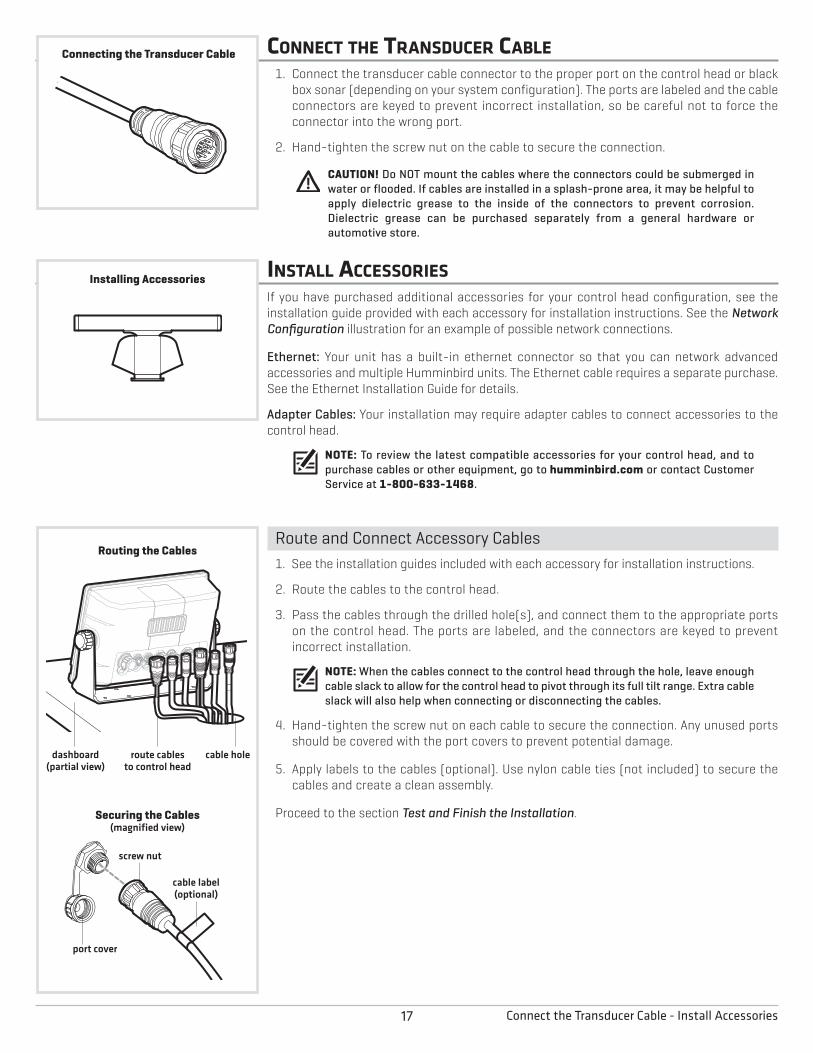
CONNECT THE TRANSDUCER CABLE1. Connect the transducer cable connector to the proper port on the control head or black
box sonar (depending on your system configuration). The ports are labeled and the cableconnectors are keyed to prevent incorrect installation, so be careful not to force theconnector into the wrong port.
2. Hand-tighten the screw nut on the cable to secure the connection.
CAUTION! Do NOT mount the cables where the connectors could be submerged inwater or flooded. If cables are installed in a splash-prone area, it may be helpful toapply dielectric grease to the inside of the connectors to prevent corrosion.Dielectric grease can be purchased separately from a general hardware orautomotive store.
INSTALL ACCESSORIESIf you have purchased additional accessories for your control head configuration, see theinstallation guide provided with each accessory for installation instructions. See the NetworkConfiguration illustration for an example of possible network connections.
Ethernet: Your unit has a built-in ethernet connector so that you can network advancedaccessories and multiple Humminbird units. The Ethernet cable requires a separate purchase.See the Ethernet Installation Guide for details.
Adapter Cables: Your installation may require adapter cables to connect accessories to thecontrol head.
NOTE: To review the latest compatible accessories for your control head, and topurchase cables or other equipment, go to humminbird.com or contact CustomerService at 1-800-633-1468.
Route and Connect Accessory Cables1. See the installation guides included with each accessory for installation instructions.
2. Route the cables to the control head.
3. Pass the cables through the drilled hole(s), and connect them to the appropriate portson the control head. The ports are labeled, and the connectors are keyed to preventincorrect installation.
NOTE: When the cables connect to the control head through the hole, leave enoughcable slack to allow for the control head to pivot through its full tilt range. Extra cableslack will also help when connecting or disconnecting the cables.
4. Hand-tighten the screw nut on each cable to secure the connection. Any unused portsshould be covered with the port covers to prevent potential damage.
5. Apply labels to the cables (optional). Use nylon cable ties (not included) to secure thecables and create a clean assembly.
Proceed to the section Test and Finish the Installation.
route cablesto control head
cable holedashboard(partial view)
Routing the Cables
cable label(optional)
port cover
screw nut
Securing the Cables(magnified view)
Installing Accessories
Connecting the Transducer Cable
18Install Accessories
NOTE: To view more examples of network configurations, visit our Web site at humminbird.com.
Power/Speed/Temp
Sonar/Temp
Video Out
Ethernet
NMEA 2000
NMEA 0183 (1-2)
Radar AS 360
Gigabit Ethernet Switch TV
Engine Monitor
Compass/GPS
Power
Speed and Temp
Sonar with Temp
Network Configuration
19 Connect the Control Head Power Cable
CONNECT THE CONTROL HEAD POWER CABLEA 6 ft (2 m) power cable is included to connect power to the control head. You may shortenor lengthen the cable using 18 gauge multi-stranded copper wire.
CAUTION! Some boats have 24 or 36 Volt electric systems, but the control head MUSTbe connected to a 12 VDC power supply.
WARNING! Humminbird is not responsible for over-voltage or over-current failures.The control head must have adequate protection through the proper selectionand installation of a 5 Amp fuse (recommended fuse type: slow-blow, time-delay, ortime-lag).
Connect to PowerThe power cable can be connected to a fuse panel (usually located near the console) or toa battery switch.
1. Make sure that the power cable is disconnected from the control head.
Fuse Terminal Connection2a. Use crimp-on type electrical connectors (not included) that match the terminal on the
fuse panel. Attach the black wire to ground (–), and the red wire to positive (+)12 VDCpower. Install a 5 Amp fuse (not included) for protection of the unit.
OR
Battery Switch Connection2b. Install the battery switch (not included) using the instructions provided with it. You will
also need to install an inline fuse holder and a 5 Amp fuse (not included) for protectionof the unit. Attach the black wire to (–) ground, and the red wire to (+)12 VDC power.
NOTE: In order to minimize the potential for interference with other marineelectronics, a separate power source (such as a second battery) may be necessary.
3. Route the power cable to the Humminbird control head, and insert the connector intothe POWER-SPEED-TEMP port. The ports are labeled, and the connectors are keyed toprevent incorrect installation. Hand-tighten the screw nut to secure the cableconnection.
CAUTION! Do NOT mount the cables where the connectors could be submerged inwater or flooded. If cables are installed in a splash-prone area, it may be helpful toapply dielectric grease to the inside of the connectors to prevent corrosion.Dielectric grease can be purchased separately from a general hardware orautomotive store.
Proceed to the section Test and Finish the Installation.
Connecting the Power Cable
Battery Switch Connection
Fuse Terminal Connection
PowerCable
Fuse Terminal orBattery Switch
Black Wire (–) Ground
Red Wire (+) 12 VDC
Connecting the Power Cableto the Power-Speed-Temp Port
(magnified view)
cable label(optional)
port cover
screw nut
20Test and Finish the Installation
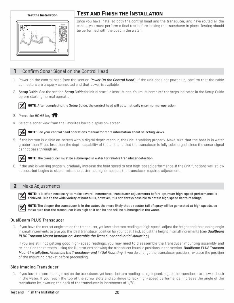
TEST AND FINISH THE INSTALLATIONOnce you have installed both the control head and the transducer, and have routed all thecables, you must perform a final test before locking the transducer in place. Testing shouldbe performed with the boat in the water.
1 | Confirm Sonar Signal on the Control Head
1. Power on the control head (see the section Power On the Control Head). If the unit does not power-up, confirm that the cableconnectors are properly connected and that power is available.
2. Setup Guide: See the section Setup Guide for initial start up instructions. You must complete the steps indicated in the Setup Guidebefore starting normal operation.
NOTE: After completing the Setup Guide, the control head will automatically enter normal operation.
3. Press the HOME key .
4. Select a sonar view from the Favorites bar to display on-screen.
NOTE: See your control head operations manual for more information about selecting views.
5. If the bottom is visible on-screen with a digital depth readout, the unit is working properly. Make sure that the boat is in watergreater than 2' but less than the depth capability of the unit, and that the transducer is fully submerged, since the sonar signalcannot pass through air.
NOTE: The transducer must be submerged in water for reliable transducer detection.
6. If the unit is working properly, gradually increase the boat speed to test high-speed performance. If the unit functions well at lowspeeds, but begins to skip or miss the bottom at higher speeds, the transducer requires adjustment.
2 | Make AdjustmentsNOTE: It is often necessary to make several incremental transducer adjustments before optimum high-speed performance isachieved. Due to the wide variety of boat hulls, however, it is not always possible to obtain high speed depth readings.
NOTE: The deeper the transducer is in the water, the more likely that a rooster tail of spray will be generated at high speeds, somake sure that the transducer is as high as it can be and still be submerged in the water.
DualBeam PLUS Transducer1. If you have the correct angle set on the transducer, yet lose a bottom reading at high speed, adjust the height and the running angle
in small increments to give you the ideal transducer position for your boat. First, adjust the height in small increments (see DualBeamPLUS Transom Mount Installation: Assemble the Transducer and Initial Mounting).
If you are still not getting good high-speed readings, you may need to disassemble the transducer mounting assembly andre-position the ratchets, using the illustrations showing the transducer knuckle positions in the section DualBeam PLUS TransomMount Installation: Assemble the Transducer and Initial Mounting. If you do change the transducer position, re-trace the positionof the mounting bracket before proceeding.
Side Imaging Transducer1. If you have the correct angle set on the transducer, yet lose a bottom reading at high speed, adjust the transducer to a lower depth
in the water. If you reach the top of the screw slots and continue to lack high-speed performance, increase the angle of thetransducer by lowering the back of the transducer in increments of 1/8".
Test the Installation
21 Test and Finish the Installation
3 | Finalize the Transducer InstallationOnce you have reached a consistently good sonar signal at the desired speeds, you are readyto lock down the transducer settings.
DualBeam PLUS Transducer1. Force the pivot to the Up position to gain access to the mounting screws, then re-align
the mounting bracket against the transom of the boat to match the traced silhouette.Check the bracket position with the level again to make sure it is still level, then markthe third mounting hole using a pencil or marker. Unscrew and remove the mountingscrews and the transducer assembly and set aside.
2. Drill the third mounting hole, using a 5/32" drill bit. Use a marine-grade silicone sealantto fill all three drilled mounting holes, especially if the holes penetrated the transomwall.
NOTE: On fiberglass hulls, it is best to use progressively larger drill bits to reduce thechance of chipping or flaking the outer coating.
3. Re-position the transducer assembly against the transom of the boat, then hand-install all three screws. Make sure that the transducer location and the pivot angle havenot changed, then fully tighten all three mounting screws. Hand-tighten only!
4. Snap the pivot back down. If you have performed the preceding procedures correctly,the transducer should be level and at the right height for optimal operation.
Lock Down the DualBeam PLUS Transducer (optional)
The following procedures are for the DualBeam PLUS transom mount transducer only.
NOTE: You have the option to lock down the Two Piece Kick-Up bracket if you do notwant the transducer to kick up. Be aware, however, that the transducer can be damagedif it is locked down and it strikes debris in the water.
1. To lock down the transducer, trace the position of the mounting bracket. Force the pivotto the Up position to gain access to the mounting screws, then re-align the mountingbracket against the transom of the boat to match the traced silhouette. Check thebracket position with the level again to make sure it is still level, then mark the fourthmounting hole using a pencil or marker. Unscrew and remove the mounting screws andthe transducer assembly and set aside.
2. Drill the fourth mounting hole, using a 9/64" drill bit. Use a marine-grade siliconesealant to fill all four drilled mounting holes, especially if the holes penetrate thetransom wall.
3. Re-position the transducer assembly against the transom of the boat, then hand installthe first three screws (two on the outside edges and one in the 3rd mounting hole).Make sure that the transducer location and the pivot angle have not changed, thenfully tighten all three mounting screws. Hand-tighten only!
4. Snap the pivot back down. Install the #8 x 1" wood screw into the 4th hole to lock downthe pivot arm. Hand-tighten only!
Side Imaging Transducer1. Once you have reached a consistently good sonar signal at the desired speeds, fully
tighten your assembly to lock it into place.
3rd mounting hole
4th mounting hole
Fully Tightening All ThreeMounting Screws
Locking Down the 200/50 kHzTransducer (optional)
Drilling the Third Mounting Hole
Locking Down the 200/83 kHzTransducer (optional)
22Power On the Control Head - Setup Guide
POWER ON THE CONTROL HEADUse the procedures in this section to power on and power off the control head.
Power On
1. Press and hold the POWER key .
First Power On: On the first power on after installation, theWelcome Menu displays on the screen.
2a. Select Start Normal Mode.
2b. International Units only: Select Language to select the languagedisplayed on the control head.
3. Selecting Start Normal Mode launches the Setup Guide. Proceedto the section Setup Guide for instructions.
Cross Touch: The Cross Touch feature allows you to use the touch screenor press the control head keys to select menus and start actions on thecontrol head. See the Quick Start Guide for more information.
Power Off
1. Press and hold the POWER key .
SETUP GUIDEThe Setup Guide is a first time setup tool to help you configure basic system preferences, such as the sonar source and mapsource. The following sections provide basic instructions for each step of the Setup Guide.
See the Quick Start Guide and your control head operations manual for more information about the menu system.
NOTE: All settings are automatically saved.
NOTE: The Setup Guide settings can be changed at any time. See each menu option in the menu system for details. See yourcontrol head operations manual for more information.
First-Time Setup | Begin Manual Setup
1. Select Begin Manual Setup to manually select the settings.
Selecting Begin Manual Setup will automatically open the firstmenu dialog box.
currently selected menu optionmenu name
Welcome Menu
OR
tap to select select open
+
23 Setup Guide
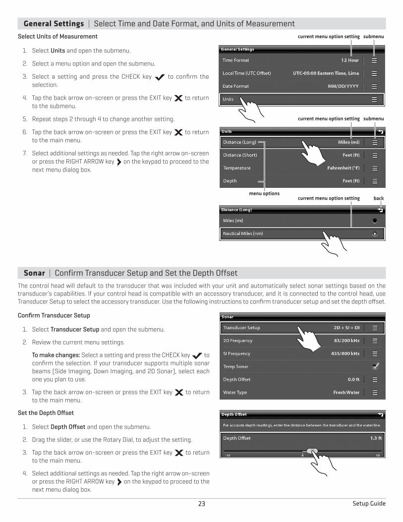
General Settings | Select Time and Date Format, and Units of MeasurementSelect Units of Measurement
1. Select Units and open the submenu.
2. Select a menu option and open the submenu.
3. Select a setting and press the CHECK key to confirm theselection.
4. Tap the back arrow on-screen or press the EXIT key to returnto the submenu.
5. Repeat steps 2 through 4 to change another setting.
6. Tap the back arrow on-screen or press the EXIT key to returnto the main menu.
7. Select additional settings as needed. Tap the right arrow on-screenor press the RIGHT ARROW key on the keypad to proceed to thenext menu dialog box.
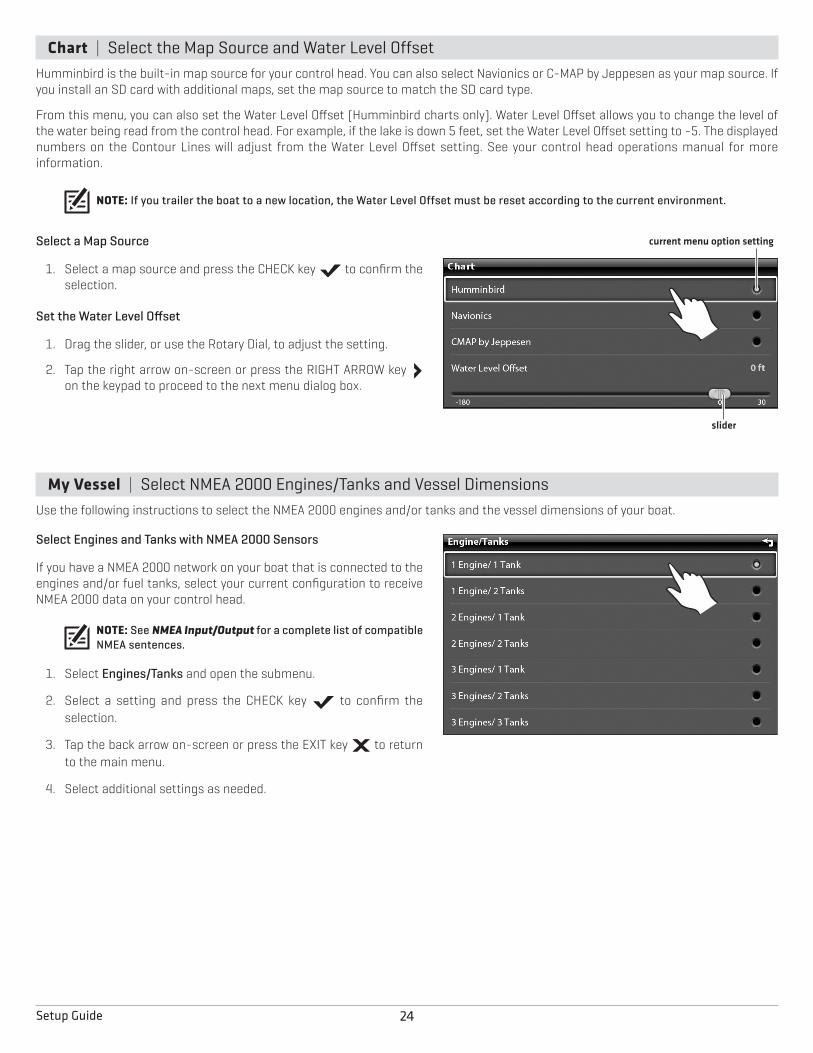
Sonar | Confirm Transducer Setup and Set the Depth OffsetThe control head will default to the transducer that was included with your unit and automatically select sonar settings based on thetransducer’s capabilities. If your control head is compatible with an accessory transducer, and it is connected to the control head, useTransducer Setup to select the accessory transducer. Use the following instructions to confirm transducer setup and set the depth offset.
Confirm Transducer Setup
1. Select Transducer Setup and open the submenu.
2. Review the current menu settings.
To make changes: Select a setting and press the CHECK key toconfirm the selection. If your transducer supports multiple sonarbeams (Side Imaging, Down Imaging, and 2D Sonar), select eachone you plan to use.
3. Tap the back arrow on-screen or press the EXIT key to returnto the main menu.
Set the Depth Offset
1. Select Depth Offset and open the submenu.
2. Drag the slider, or use the Rotary Dial, to adjust the setting.
3. Tap the back arrow on-screen or press the EXIT key to returnto the main menu.
4. Select additional settings as needed. Tap the right arrow on-screenor press the RIGHT ARROW key on the keypad to proceed to thenext menu dialog box.
menu options
current menu option setting
back
submenu
current menu option setting submenu
current menu option setting
24Setup Guide
Chart | Select the Map Source and Water Level OffsetHumminbird is the built-in map source for your control head. You can also select Navionics or C-MAP by Jeppesen as your map source. Ifyou install an SD card with additional maps, set the map source to match the SD card type.
From this menu, you can also set the Water Level Offset (Humminbird charts only). Water Level Offset allows you to change the level ofthe water being read from the control head. For example, if the lake is down 5 feet, set the Water Level Offset setting to -5. The displayednumbers on the Contour Lines will adjust from the Water Level Offset setting. See your control head operations manual for moreinformation.
NOTE: If you trailer the boat to a new location, the Water Level Offset must be reset according to the current environment.
Select a Map Source
1. Select a map source and press the CHECK key to confirm theselection.
Set the Water Level Offset
1. Drag the slider, or use the Rotary Dial, to adjust the setting.
2. Tap the right arrow on-screen or press the RIGHT ARROW keyon the keypad to proceed to the next menu dialog box.
My Vessel | Select NMEA 2000 Engines/Tanks and Vessel DimensionsUse the following instructions to select the NMEA 2000 engines and/or tanks and the vessel dimensions of your boat.
Select Engines and Tanks with NMEA 2000 Sensors
If you have a NMEA 2000 network on your boat that is connected to theengines and/or fuel tanks, select your current configuration to receiveNMEA 2000 data on your control head.
NOTE: See NMEA Input/Output for a complete list of compatibleNMEA sentences.
1. Select Engines/Tanks and open the submenu.
2. Select a setting and press the CHECK key to confirm theselection.
3. Tap the back arrow on-screen or press the EXIT key to returnto the main menu.
4. Select additional settings as needed.
current menu option setting
slider
25 Setup Guide
Set Vessel Dimensions
It is important to set the height, width, and depth allowances required foryour vessel as that information affects the accuracy of auto routecalculations during navigation.
1. Select Vessel Dimensions and open the submenu.
2. Select a setting. Drag the slider, or use the Rotary Dial, to adjust thesetting.
3. Select additional settings as needed.
4. Tap the back arrow on-screen or press the EXIT key to returnto the main menu.
5. Select Confirm to confirm the selected settings.
The unit will automatically enter normal operation.
26Set Up the Control Head
SET UP THE CONTROL HEADAfter completing the Setup Guide, use the following sections to configure basic system settingsand confirm operation.
NOTE: See the Quick Start Guide and the control head operations manual that wasprovided with your unit for additional information.
Start Radar TransmissionIf you have a radar connected to the control head system, use thefollowing instructions to start radar transmission.
WARNING! The radar must be configured before it can be usedfor on-the-water operations. See the operations manual forconfiguration instructions.
Start Radar Transmission
1. Confirm the radar power source is turned on (breaker or switch).
2. Press the HOME key .
3. Tap the Radar View on the Favorites Bar, or use the Joystick toselect it and press the CHECK key to open.
4. With the Radar View open on-screen, press the MENU key .
5. Turn Transmit ON. A radar icon will appear in the system status barconfirming the radar is transmitting (see Confirm SensorConnection).
Use the same instructions to turn Radar Transmit off.
Confirm Radar TransmissionRadar icon is displayed in the system status bar.
Transmit is ON. Radar data is displayed on-screen.
Favorites Bar
Home Screen
27 Set Up the Control Head
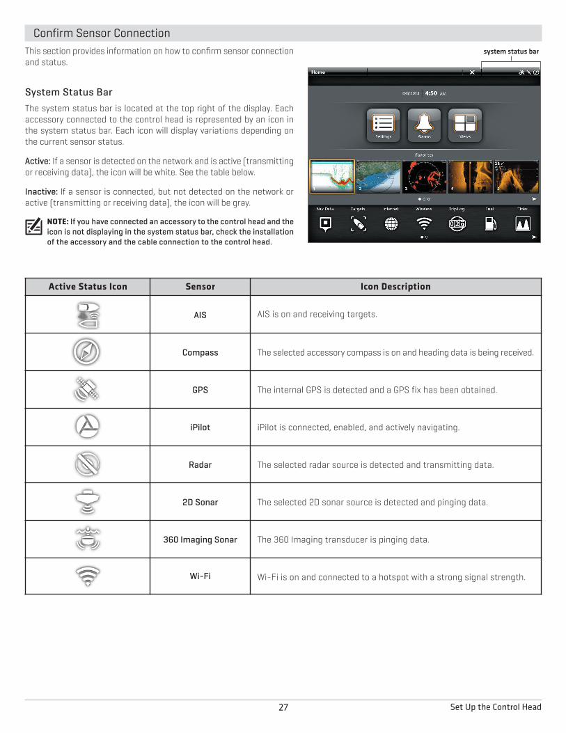
Confirm Sensor ConnectionThis section provides information on how to confirm sensor connectionand status.
System Status BarThe system status bar is located at the top right of the display. Eachaccessory connected to the control head is represented by an icon inthe system status bar. Each icon will display variations depending onthe current sensor status.
Active: If a sensor is detected on the network and is active (transmittingor receiving data), the icon will be white. See the table below.
Inactive: If a sensor is connected, but not detected on the network oractive (transmitting or receiving data), the icon will be gray.
NOTE: If you have connected an accessory to the control head and theicon is not displaying in the system status bar, check the installationof the accessory and the cable connection to the control head.
Active Status Icon Sensor Icon Description
AIS AIS is on and receiving targets.
Compass The selected accessory compass is on and heading data is being received.
GPS The internal GPS is detected and a GPS fix has been obtained.
iPilot iPilot is connected, enabled, and actively navigating.
Radar The selected radar source is detected and transmitting data.
2D Sonar The selected 2D sonar source is detected and pinging data.
360 Imaging Sonar The 360 Imaging transducer is pinging data.
Wi-Fi Wi-Fi is on and connected to a hotspot with a strong signal strength.
system status bar
28Set Up the Control Head
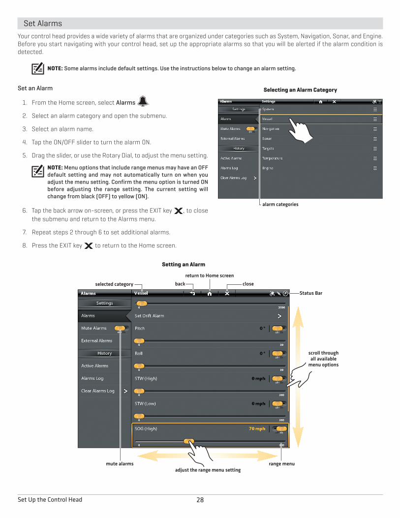
Set AlarmsYour control head provides a wide variety of alarms that are organized under categories such as System, Navigation, Sonar, and Engine.Before you start navigating with your control head, set up the appropriate alarms so that you will be alerted if the alarm condition isdetected.
NOTE: Some alarms include default settings. Use the instructions below to change an alarm setting.
Set an Alarm
1. From the Home screen, select Alarms .
2. Select an alarm category and open the submenu.
3. Select an alarm name.
4. Tap the ON/OFF slider to turn the alarm ON.
5. Drag the slider, or use the Rotary Dial, to adjust the menu setting.
NOTE: Menu options that include range menus may have an OFFdefault setting and may not automatically turn on when youadjust the menu setting. Confirm the menu option is turned ONbefore adjusting the range setting. The current setting willchange from black (OFF) to yellow (ON).
6. Tap the back arrow on-screen, or press the EXIT key , to closethe submenu and return to the Alarms menu.
7. Repeat steps 2 through 6 to set additional alarms.
8. Press the EXIT key to return to the Home screen.
selected category back
Setting an Alarm
closereturn to Home screen
Status Bar
range menumute alarmsadjust the range menu setting
scroll throughall availablemenu options
Selecting an Alarm Category
alarm categories
29 Set Up the Control Head
Display a Data Bar
Your control head allows you to choose a standard data bar or a navigation data bar with preset data boxes. If you attach additionalaccessories to the control head or network, additional data bar options may also be displayed. The data boxes in the data bar can also bechanged.
Select the Data Bar Type
1. With a view displayed on-screen, press the PANE key once. Ina multi-pane view, press the PANE key repeatedly until the statusbar turns yellow.
2. Press the MENU key once.
3. Select Data Bar from the View Options Menu.
4. Select the type of data bar to display. To hide the data bar, selectOff.
Customize the Data Bar
Your control head provides a wide variety of data types (categories),including Vessel, Navigation, Speed, Wind, Fuel, and Engine, with multipledata box options. The data bars can be customized with the data boxesyou select. See your control head operations manual for moreinformation.
Set the Trip Log
The Trip Log provides current navigation data, such as Speed OverGround (SOG), timer for elapsed time, distance traveled since last reset,average speed, and trip fuel.
Turn On the Trip Log
1. From the Home screen, select the Trip Log tool .
2. Under Trip Log, select Trip.
3. Select Trip Log and tap the ON/OFF slider to turn Trip Log ON.
Use the same instructions to turn the Trip Log off.
Starting the Trip Logreturn to Home screen close
Trip Log data boxes
Down Imaging View with Data Bar Displayed
standard data bar
30Manage Your Control Head
MANAGE YOUR CONTROL HEADWARNING! Humminbird is not responsible for the loss of data files (waypoints, routes, tracks, groups, snapshots, recordings, etc.)that may occur due to direct or indirect damage to the unit’s hardware or software. It is important to back up your control head’sdata files periodically. Data files should also be saved to your PC before restoring the unit’s defaults or updating the software. Seeyour Humminbird online account at humminbird.com and the operations manual on your Humminbird Manual CD for details.
Rename Your Control HeadUse the following instructions to rename your control head.
1. From the Home screen, select Settings .
2. Select Network.
3. Select System Info.
4. Select Rename Unit. Using the on-screen keyboard orkeypad, enter the name you would like to use for your controlhead. Select Save.
You can use the same instructions to rename the Network, underNetwork Info.
Register Your Humminbird UnitSet up an online account so that you will receive the latestHumminbird news, including accessory compatibility and softwareupdate information.
1. Go to our Web site at humminbird.com, and click MyAccount.
2. Follow the on-screen instructions to create a new account.Then, click Register a Product.
Save System Settings to an SD CardYou can save your customized system settings to an SD Card. Thisallows you to import your favorite settings to another control heador to a control head that has been restored to its factory settings.
1. Insert an SD Card into one of the SD Card slots on thecontrol head.
2. From the Home screen, select the Files tool .
3. Under Export, select Menu Settings.
4. Follow the on-screen prompts to export the menu settingsto the SD Card.
You can use the same instructions to import saved settings tothe control head. Select Import > Menu Settings.
Humminbird Manuals on CDThe CD included with your control head contains the operationsmanuals (and other related manuals) for your Humminbird product.To open, read, and print the Adobe PDF files, you will need AdobeReader software installed on your computer.
To download the free Adobe Reader Software to your computer, visithttp://get.adobe.com/reader.
1. Insert the CD into your computer’s CD drive.
2. From the on-screen window, click Open Folder to View Files.
NOTE: If the window does not automatically open,locate the CD drive from your desktop and double-click the CD title to open the folder.
3. Under Files Currently on the Disc, select a manual folder anddouble-click to open.
4. Select a language folder. Double-click the folder to view theincluded PDF files. (EN = English, FR = French)
5. Double-click the PDF file to open the manual.
PDF File Tips (also see Adobe Reader Help):
• In the Bookmarks Panel, click a section name to jump to aspecific section of the manual. Bookmarks can be expandedand collapsed by clicking on the plus (+) or minus (-) icons.
• To search words or phrases throughout the manual, pressCtrl F and type the word(s) into the text box.
*The included CD is not a DVD.
Update the Control Head SoftwareIf your model can be updated, you can download software updatesfrom your Humminbird online account.
1. Log into your account at humminbird.com.
2. From the My Equipment tab, click the file name of the latestcontrol head software update (unit name [version #]).
• Read the instructions in the dialog box and click Download.
• Follow the on-screen instructions to save the software fileto the SD Card.
3. Install the SD card with the software file into your controlhead card slot. Press the POWER key to power on yourcontrol head. The unit will recognize the new software andrun through a series of prompts to confirm the softwareinstallation.
31 NMEA Input/Output
NMEA INPUT/OUTPUTYour control head is compatible with the NMEA 0183 and NMEA 2000 sentences shown in the following sections.
NOTE: Humminbird verifies maximum stated depth in saltwater conditions, but actual depth performance may vary due totransducer installation, water type, thermal layers, bottom composition, and slope.
NOTE: Product specifications and features are subject to change without notice.
NOTE: Humminbird verifies maximum stated depth in saltwater conditions, but actual depth performance may vary due totransducer installation, water type, thermal layers, bottom composition, and slope.
NOTE: Product specifications and features are subject to change without notice.
NOTE: Humminbird verifies maximum stated depth in saltwater conditions, but actual depth performance may vary due totransducer installation, water type, thermal layers, bottom composition, and slope.
NOTE: Product specifications and features are subject to change without notice.
NOTE: Humminbird verifies maximum stated depth in saltwater conditions, but actual depth performance may vary due totransducer installation, water type, thermal layers, bottom composition, and slope.
NOTE: Product specifications and features are subject to change without notice.
SPECIFICATIONS
38Maintenance
MAINTENANCEYour control head is designed to provide years of trouble-free use with very little maintenance. Use the following procedures to ensureyour Humminbird continues to deliver top performance.
Control Head MaintenanceIt is important to consider the following precautions when using your Humminbird control head:
• Chemicals, such as those found in bug spray and sunscreen, may cause permanent damage to the control head screen. Suchdamage is not covered by the warranty.
• NEVER leave the control head in a closed car or trunk. The high temperatures generated in hot weather can damage theelectronics.
• When the control head is not in use, cover the unit with the control head cover.
• Repairs should be performed only by an authorized technician.
Use the following information to keep the control head and screen clean.
• Screen: To clean the control head screen, use a mild soap (such as a non-abrasive liquid hand soap) and warm water. Wipe thescreen dry with a soft cloth. Be careful to avoid scratching the screen. If water spots remain, use a solution of water and vinegar.
WARNING! Do not use a chemical glass cleaner on the screen. Chemicals in the solution may cause cracking in the lens of the unit.
NOTE: Do not wipe the screen while dirt or grease is on the screen.
• Control Head: If the control head comes into contact with salt spray, wipe the affected surfaces with a cloth dampened with freshwater.
Transducer MaintenanceUse the following information to maintain the transducer operation.
• If your boat remains in the water for long periods of time, algae and other marine growth can reduce the effectiveness of thetransducer. Periodically clean the face of the transducer with a mild, marine-safe and plastic-safe soap or solution.
NOTE: To clean the transducer, you may need to pivot the transducer up in the bracket.
• If your boat remains out of the water for a long period of time, it may take some time to wet the transducer when it is returned tothe water. Small air bubbles can climb to the surface of the transducer and interfere with proper operation. These bubblesdissipate with time, or you can wipe the face of the transducer with your fingers after the transducer is in the water.
39 Troubleshooting
TROUBLESHOOTINGBefore contacting Humminbird Customer Service, please read the following section. Taking the time to review these troubleshootingguidelines may allow you to solve a performance problem yourself, and therefore avoid sending your unit back for repair.
Control Head Doesn’t Power UpIf your control head doesn’t power up, use the Installation section of this manual for specific confirmation details, making sure that:
• the power cable is properly connected to the control head
• the power cable is wired correctly, with red to positive battery terminal and black to negative terminal or ground
• the fuse is operational
• the battery voltage of the power connector is at least 10 Volts
Correct any known problems, including removing corrosion from the battery terminals or wiring, or actually replacing the battery ifnecessary.
Control Head Doesn’t Detect the Connected TransducerA connected and functioning transducer will automatically be detected by the control head. The control head will default to thetransducer that was included with your unit and automatically select sonar settings based on the transducer’s capabilities. If, when youpower up the control head, it does not automatically select sonar settings or display sonar data, even though a transducer is alreadyconnected, this means that the control head is not detecting the transducer. Perform the following troubleshooting tasks:
• Using the Installation section of this manual, check to make sure that the transducer cable is securely connected to the controlhead. Reconnect if necessary, and power up the unit again to see if this fixes the problem.
• Replace the non-functioning transducer with a known good transducer if available and power up the control head again.
• Check the transducer cable. Replace the transducer if the cable is damaged or corroded.
40Troubleshooting
Display Problems
There are several main conditions or sources of possible interference that may cause problems with the quality of the informationdisplayed on the control head. Look in the following table for some symptoms of display problems and possible solutions:
Finding the Cause of Noise
Electrical noise usually affects the display with many black dots at high speeds, and high sensitivity readings. See the table below forpossible sources that can cause noise or interference.
Possible Source of Noise Isolation
Other electronic devicesTurn off any nearby electronic devices to see if the problem goes away, then turn themon one at a time to see if the noise re-appears.
The boat’s engine
To determine whether the boat’s engine is the source of the noise, increase the RPMswhile the boat is in neutral and stationary to see if the noise increases proportionately;if the noise appears when you rev the engine, the problem could be the spark plugs,alternator, or tachometer wiring. Replace the spark plugs with resistor plugs, install analternator filter, or route the control head power and transducer cables away from theengine wiring.
Cavitation from the boat’s propeller
Turbulence created by the propeller can cause noise. Confirm the transducer has beenproperly installed according to its specific mounting requirements (see TransomTransducer Mounting Requirements and Side Imaging Transducer MountingRequirements). Also, make sure that the water flows smoothly over the face of thetransducer at all times.
Display Problems Possible Solutions
The control head loses power at highspeeds.
If the power output of your boat’s engine is unregulated, the control head may beprotecting itself using its over-voltage protection feature. Make sure the input voltagedoes not exceed 20 Volts.
When the boat moves at higher speeds,the bottom disappears or suddenlyweakens, or the display contains gaps.
The transducer position may need to be adjusted. A mix of air and water flowing aroundthe transducer (cavitation) may be interfering with the interpretation of sonar data.See the installation section for your transducer for instructions on adjusting thetransducer position.
Electrical noise from the boat’s engine may be interfering with sonar reception. SeeFinding the Cause of Noise for more information.
There are no fish detected, even whenyou know they are in the water under theboat, or sonar readings seem weak orfaulty.
Sonar readings may be affected if the transducer is not positioned correctly (i.e.mounted at an angle, not straight down), or there is some kind of mechanicalinterference, either because it is mounted inside a hull that is too thick for proper sonartransmission, the bond between the transducer and the hull is not airtight, or becausethe transducer is dirty. See the installation section for your transducer for instructionson adjusting the transducer position, and make sure the transducer is clean.
Low battery voltage may be affecting the power of signal transmission.
Electrical noise from the boats engine may be interfering with sonar reception. SeeFinding the Cause of Noise for more information.
SIDE IMAGING TRANSDUCER MOUNTING TEMPLATEIf you are reproducing or printing this template from an electronic file, start with the following print settings:
• Scale = None
• Paper = 8.5 x 11 inches
• Layout = Portrait
Confirm the template matches the transducer bracket slots and adjust the print as needed.
Drill
Drill
Drill
Use 5/32II
drill bit.
TOP
PLACE EITHER CORNERON DEADRISE ANGLE
Remove and use fortransducer installation
41 Side Imaging Transducer Mounting Template
42Contact Humminbird
CONTACT HUMMINBIRDContact Humminbird Customer Service in any of the following ways: