ONLINE POSITION CONTROL SYSTEM USING INCREMENTAL FUZZY CONTROL WAN HAMIDAH BINTI WAN ABAS A project report submitted in partial fulfillment of the requirement for the award of the Degree of Master of Electrical Engineering Faculty of Electrical and Electronic Engineering Universiti Tun Hussein Onn Malaysia JULY 2014
Transcript
ONLINE POSITION CONTROL SYSTEM USING INCREMENTAL FUZZY
CONTROL
WAN HAMIDAH BINTI WAN ABAS
A project report submitted in partial
fulfillment of the requirement for the award of the
Degree of Master of Electrical Engineering
Faculty of Electrical and Electronic Engineering
Universiti Tun Hussein Onn Malaysia
JULY 2014
v
ABSTRACT
In the field of fuzzy control theory, fuzzy logic controllers is one of the most active
research areas and are particularly useful in controlling various types of physical
processes. Therefore, this project also involved in usage of the fuzzy logic controller.
Main objective of this project is to develop online position control of DC motor
using Incremental Fuzzy Logic Controller (IFLC). The IFLC were developed by
using MATLAB Simulink and implemented in the real position control system
hardware. RAPCON platform is a hardware that was implemented in real-time
session with DC motor. For simulation, signal generator used as the reference input
in the form of square wave. The best gains used for the IFLC in simulation are: gain
of error (GE) is 2.721, gain of change error (GCE) is 0.019 and gain of output (GCU)
is 0.259. While real-time simulation use the most gains such as gain error (GE) of
1.785, gain of change error (GCE) is 0.0056955 and gain of output (GCU) is 0.01.
Both method either simulation or real-time generate in 20 seconds. The result was
obtained in form of graph and their performance was analysed. Based on the result,
the IFLC shows the better performance of the overshoot percentage (%OS) of 0%.
vi
ABSTRAK
Dalam bidang teori kawalan kabur, pengawal logik kabur merupakan satu bidang
penyelidikan yang sangat aktif dan berguna dalam mengawal beberapa jenis proses
fizikal. Oleh itu, projek ini juga termasuk dalam penggunaan pengawal logik kabur.
Tujuan utama projek ini adalah untuk membina kawalan kedudukan secara talian
bagi motor AT (arus terus) dengan menggunakan pengawal logik kabur tambahan
(PLKT). PLKT telah dibangunkan dengan menggunakan MATLAB Simulink dan
dilaksanakan dalam perkakasan sistem kawalan kedudukan sebenar. RAPCON
platfom merupakan perkakasan yang digunakan dalam sesi masa-sebenar bersama
motor AT. Bagi simulasi, penjana isyarat digunakan sebagai masukan rujukan dalam
bentuk gelombang persegi. Gandaan yang digunakan bagi PLKT dalam simulasi
adalah: ralat gandaan (GE) adalah 2.721, perubahan ralat gandaan (GCE) adalah
0.019 dan gandaan keluaran (GCU) adalah 0.259. Sementara simulasi masa-sebenar
banyak menggunakan gandaan seperti ralat gandaan (GE) adalah 1.785, perubahan
ralat gandaan (GCE) adalah 0.0056955 dan gandaan keluaran (GCU) adalah 0.01.
Setelah simulasi dan scenario masa-sebenar telah berjaya, keputusan yang yang
diperolehi adalah dalam bentuk graf dan prestasinya dianalisis. Berdasarkan kepada
keputusan yang diperolehi, PLKT menunjukkan perlaksanaannya yang amat baik
dengan peratus lajakan lampau maksimum (%OS) adalah 0%.
vii
CONTENTS
TITLE i
DECLARATION ii
DEDICATION iii
ACKNOWLEDGEMENT iv
ABSTRACT v
CONTENTS vii
LIST OF TABLES x
LIST OF FIGURES xii
LIST OF SYMBOLS AND ABBREVIATIONS xiv
CHAPTER 1 INTRODUCTION 1
1.1 Introduction 1
1.2 Problem Statement 2
1.3 Project Objectives 2
1.4 Project Scope 3
1.5 Project Outline 3
CHAPTER 2 LITERATURE REVIEW 4
2.1 Introduction 4
2.2 Previous Work 4
2.3 DC Motor Theory 6
2.3.1 Mathematical Equation 7
2.3.2 Transfer Function 8
viii
2.4 Control Requirement 9
2.5 PID Controller 10
2.6 Incremental Fuzzy Logic 12
CHAPTER 3 METHODOLOGY 15
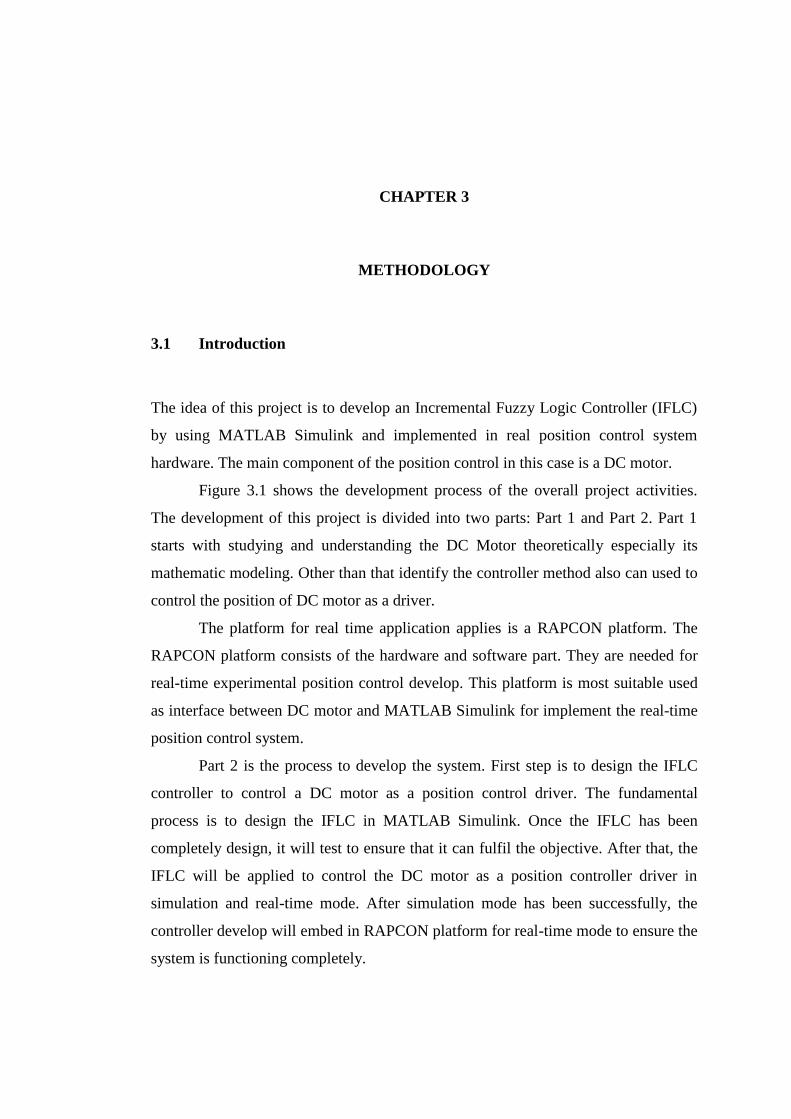
3.1 Introduction 15
3.2 Concept of The Project 17
3.3 Fuzzy Logic Controller Design 17
3.3.1 Mamdani Fuzzy Logic Control 19
3.3.2 Fuzzy Rule Base System 20
3.4 RAPCON Board 20
3.4.1 Specification 21
3.4.2 Hardware 22
3.4.3 Software 24
3.5 Hardware Connection 25
3.6 DC Motor With Encoder 25
CHAPTER 4 RESULT AND ANALYSIS 28
4.1 Introduction 28
4.2 DC Motor System Response 29
4.3 Incremental Fuzzy Controller Test 30
4.4 Incremental Fuzzy Controller with RAPCON 41
(Real-Time Experiment)
4.5 Discussion 51
CHAPTER 5 CONCLUSION AND RECOMMENDATION 52
5.1 Conclusion 52
5.2 Recommendation 53
ix
REFERENCES 54
VITA 57
x
LIST OF TABLES
3.1 Rule Base for fuzzy controller 20
3.2 Specification of the RAPCON platform 21
3.3 Summary part of the RAPCON board functional
block diagram
23
3.4 The DC motor parameters 26
4.1 IFLC controller parameter values 32
4.2 Reference input values setting 32
4.3 Specifications of parameter associated with response
at 360°
34
4.4 Specifications of parameter associated with response
at 330°
34
4.5 Specifications of parameter associated with response
at 300°
35
4.6 Specifications of parameter associated with response
at 270°
36
4.7 Specifications of parameter associated with response
at 240°
37
4.8 Specifications of parameter associated with response
at 210°
37
4.9 Specifications of parameter associated with response
at 180°
38
4.10 Specifications of parameter associated with response
at 150°
39
4.11 Specifications of parameter associated with response
at 120°
39
4.12 Specifications of parameter associated with response
at 90°
40
xi
4.13 Specifications of parameter associated with response
at 60°
41
4.14 IFLC controller parameter values 42
4.15 Reference input values setting 42
4.16 Specifications of parameter associated with response
at 360°
44
4.17 Specifications of parameter associated with response
at 330°
44
4.18 Specifications of parameter associated with response
at 300°
45
4.19 Specifications of parameter associated with response
at 270°
46
4.20 Specifications of parameter associated with response
at 240°
46
4.21 Specifications of parameter associated with response
at 210°
47
4.22 Specifications of parameter associated with response
at 180°
48
4.23 Specifications of parameter associated with response
at 150°
48
4.24 Specifications of parameter associated with response
at 120°
49
4.25 Specifications of parameter associated with response
at 90°
50
4.26 Specifications of parameter associated with response
at 60°
50
xii
LIST OF FIGURES
2.1 Crisp PD control system 5
2.2 Output and control signals for crisp PD control
system
5
2.3 Separately excited DC motors 6
2.4 Response specification 9
2.5 General feedback control architecture 10
2.6 Functional diagram of a PID Control Loop 11
2.7 Incremental Fuzzy Controller 13
3.1 Flow chart for develop project 16
3.2 Block diagram of position control using IFLC system 17
3.3 Block diagram of fuzzy controller system 18
3.4 Fuzzy Inference System (FIS) 19
3.5 The Input and Output of variable 19
3.6 The functional block diagram of the RAPCON board 22
3.7 RAPCON Board (hardware) 24
3.8 RAPCON Software 24
3.9 Interfacing between Personal computer and DC
Motor using RAPCON Board
25
3.10 DC motor with encoder 26
3.11 Block diagram of DC motor 27
4.1 Hardware connection 28
4.2 Open loop of DC motor diagram 29
4.3 Open loop of DC motor response 29
4.4 Close loop of DC motor diagram 30
4.5 Close loop of DC motor response 30
4.6 IFLC controller in subsystem form 31
4.7 Complete design of IFLC controller system 31
xiii
4.8 Output response at 360 degree 33
4.9 Zooming of output response at 360 degree 33
4.10 Output response at 330 degree 34
4.11 Output response at 300 degree 35
4.12 Output response at 270 degree 35
4.13 Output response at 240 degree 36
4.14 Output response at 210 degree 37
4.15 Output response at 180 degree 38
4.16 Output response at 150 degree 38
4.17 Output response at 120 degree 39
4.18 Output response at 90 degree 40
4.19 Output response at 60 degree 40
4.20 Incremental Fuzzy Logic controller for DC motor
system (real-time)
41
4.21 Output response based on IFLC at 360º 43
4.22 Zooming of output response based on IFLC at 360º 43
4.23 Output response based on IFLC at 330º 44
4.24 Output response based on IFLC at 300º 45
4.25 Output response based on IFLC at 270º 45
4.26 Output response based on IFLC at 240º 46
4.27 Output response based on IFLC at 210º 47
4.28 Output response based on IFLC at 180º 47
4.29 Output response based on IFLC at 150º 48
4.30 Output response based on IFLC at 120º 49
4.31 Output response based on IFLC at 90º 49
4.32 Output response based on IFLC at 60º 50
xiv
LIST OF SYMBOLS AND ABBREVIATIONS
DC - Direct Current
FIS - Fuzzy Interence System
FLC - Fuzzy Logic Controller
FPD - Fuzzy Proportional Derivative
GCE - Gain of Change Error
GE - Gain Error
GCU - Gain of Output
IFLC - Incremental Fuzzy Logic Controller
MATLAB - MATrix LABoratory
NN - Neural Network
OS - Overshoot
PD - Proportional-Derivative
PID - Proportional-Integral-Derivative
Tp - Peak Time
Tr - Rise Time
Ts - Settling Time
1
CHAPTER 1
INTRODUCTION
1.1 Introduction
DC motor has been widely used to improve the quality of human work, either
globally or individually such as in home appliances, industrial applications, robot
manipulators etc. The DC motors are choosing because it has high reliabilities,
flexibilities and low costs. Most of the applications of DC motor drivers are need a
position control and speed.
There are many methods used as DC motor drivers such as PID, NN, Fuzzy
Logic etc. Some applications may require using only one or two actions to provide
the appropriate system control.
“Proportional-Integral-Derivative (PID) controllers are commonly used for
motor control applications because of their simple structures and intuitionally
comprehensible control algorithms” (Manafeddin Namazov and Onur Basturk,
2010). “The PID controller has been implemented in position control system, but still
suffers from poor performance because of non-linear parameters. The PID does not
give satisfactory results when control parameters, loading conditions and the motor
itself are changed” (Mohammad Syah Rizal, 2013).
Neural Network (NN) controllers are another method used for motor control
applications. In the NN, there is abundant of architecture can be used to perform a
variety types of functions. There are kind of neural network with high efficiency and
strong function generalizing in terms of learning speed and simplicity of the
structure. The NN need increasing the number input neural network and put some
delay to the input neural network to improve performance of the network
(Mohammad Syah Rizal, 2013). In this project, the fuzzy logic controller (FLC) as
an intelligent controller will apply. The FLC can be designed without the exact
2
model of the system. Fuzzy logic is based on the principle of human expert decision
making in problem solving mechanism (Dirman et. all, 2011).
By using the FLC, the position control performance will improve. This FLC
develop will use Mamdani method. Mamdani method is widely accepted for
capturing expert knowledge. Computer simulation is guided to illustrate the
performance and show the result.
1.2 Problem Statements
Normally, the DC motor controller has a problem to achieve the desire position
control. This problem among other is affected by the existing the nonlinearities
component in the system. Moreover, these nonlinearities are often unknown and
decrease the performance of position control. PID controller has been used because it
most simple and easy to implement, but this type of controller still not able to
improve the position control system performance because of the nonlinearities and
uncertainties issues. The PID controller is not able to work well for non-linear
system, and particularly complex and vague system that has no precise mathematical
models. Some researchers used NN controller to improve the performance of
position control, but it’s still not have a good performance. To overcome these
problems, the Incremental Fuzzy Control System (IFLC) is developed in this project
to ensure the DC motor as a position control driver is operable in any circumstance
of situations.
1.3 Project Objectives
The major objective of this research is to use the incremental fuzzy logic control to
develop online position control. Its measurable objectives are as follows:
1. To design the incremental fuzzy control system for position control with DC
motor as a driver.
2. To implement an online position control based on incremental fuzzy control
system.
3. To test the performance of position control based on incremental fuzzy.
3
1.4 Project Scopes
The scopes of this project are as follows:
a) MATLAB Simulink software is used to simulate the incremental fuzzy logic
controller system developed.
b) The controller type is an Incremental Fuzzy Logic Control system.
c) DC motor is as a driver of the position control.
d) The controller develop is an online.
e) Interfacing between personal computer (pc) where the controller is build and
DC motor as a plant is done by RAPCON Board.
f) The type of layout is square wave.
1.5 Report Outline
This project deals with the proposed idea of develop a position control system for DC
motor by using an Incremental Fuzzy Logic Controller (IFLC). This report is divided
into five chapters. Chapter 1 is an introduction and gives an overview of the project and
speaks about the scope and the main objective. Chapter 2 discusses briefly about the DC
motor theory, PID controller and Incremental Fuzzy Logic Controller. Chapter 3
explained the method that was used in this project. Among the subtopics described are
flow chart for develop project, flow chart for the IFLC system, IFLC design, hardware
and software RAPCON, and concept of the project. Chapter 4 describes the MATLAB
Simulink model for IFLC system of position control. It also shows the result of
simulation and real-time experiment. And the last chapter is Chapter 5. This chapter is
about the conclusion and the future scope of the designed controller.
1
CHAPTER 2
LITERATURE REVIEW
2.1 Introduction
This chapter will discuss the previous studies that have been accomplished by other
researchers in same area. There are many researchers who have been implemented
fuzzy logic control on the position control with DC motor as a driver. Related to this
project title, the review focused on the incremental fuzzy control system resources
like journal, proceeding thesis and also book.
2.2 Previous Works
There are many papers have been published about fuzzy control system design for
DC motor (Manafeddin Namazov and Onur Basturk, 2010). The comparison
between Proportional-Integral-Derivative (PID) and Fuzzy Logic Controller (FLC)
application for position control has been done (Paul et.all.,1994) and the result shows
the FLC performed better than PID. Other work, based on Neural Network
controller. The results are obtained from the simulation and real-time experiment.
From the result, neural network controller has been given the best controller for
position control with DC motor as driver. The neural network controller satisfies all
the specifications underlined better than PID controller. The neural network
controller provides faster response and more precise control compared to PID
controller (Muhamad Syah Rizal, 2013).
Figure 2.1 shows the PD control system designed in MATLAB Simulink where
controller coefficients are adjusted using the Signal Constraint blocks. Integral
5
coefficient of PID controller is set to zero (i.e K = 0) (Manafeddin Namazov and Onur
Basturk, 2010).
Figure 2.1: Crisp PD control system
FLCs are complex, nonlinear controllers. Therefore it’s difficult to predict how
the rise time, settling time or steady state error is affected when controller parameters or
control rules are changed. On the contrary, PID controllers are simple, linear controllers
which consist of linear combinations of three signals (Manafeddin Namazov and Onur
Basturk, 2010).
Figure 2.2: Output and control signals for crisp PD control system
6
Figure 2.2 shows output and control signals of PD control system with
adjusted parameters.
Ankur Gupta et.all. (2011) has been presented the position control of servo
motor in three difference schemes. They are PID, Fuzzy and sliding mode Fuzzy
Control. Each of them is discussed in term of the normal case, parameter variation
case, and disturbance. The results show that PID is effective for a constant reference
input but is ineffective for parameter variation and disturbance cases. Then Fuzzy
controller gives better performance compared to PID controller but results are
ineffective for disturbance case. While sliding mode fuzzy control shows that the
system performance improvement when compared to PID and fuzzy control for
parameter variation case and for disturbance case. So sliding mode fuzzy control is
better in terms of control performance compared with other controllers.
2.3 DC Motor Theory
In armature control of separately excited DC motors, the voltage applied to the
armature of the motor is adjusted without changing the voltage applied to the field.
Figure 2.3 describes a separately excited DC motor equivalent model (Norman S.
Nise , 1995).
Figure 2.3: Separately excited DC motors
Where:
J - Moment of Inertia of the motor (kg m2)
B - Friction coefficient of the motor (Nm/rad/sec)
Ke - Torque constant of the motor (Nm/A)
7
Kb ‐ Motor back emf constant (V/rad/sec)
ia - Armature current (A)
Va - Armature voltage applied (V)
Ra - Armature resistance (ohms)
La - Armature inductance (mH)
2.3.1 Mathematical Equation
Voltage equation of the armature circuit under transient is given by
From the dynamics of motor load system
Further
When field current is kept constant, flux remains constant. Replacing Keф by a
constant Ke, yields
(2.3)
(2.4)
(2.5)
(2.6)
(2.1)
(2.2)
8
2.3.2 Transfer Function
Laplace transforms of Eq. (2.1) to Eq. (2.5) are:
Substitute Eq. (2.9) into Eq. (2.6):
Then the relation between rotor shaft speed and applied armature voltage is
represented by transfer function below:
The relation between position and speed is:
Then the transfers function between shaft position and armature voltage without load
is:
(2.7)
(2.8)
(2.9)
(2.10)
(2.11)
(2.12)
(2.13)
(2.14)
(2.15)
9
2.4 Control Requirement
The controller requirements are analyzed based on its output response parameters. It
will indicate the performance of the controller. The parameters are given below
(Norman S. Nise , 1995).
Figure 2.4: Response specification
(i) Rise time, Tr
The time required for the response to progress from 0.1 to 0.9 of the final
value.
(ii) Peak time, Tp
The time required to reach the first or maximum peak.
(iii) Settling time, Ts
The time required for the response taken to fall within and stay within 2% of
the steady-state value.
(2.16)
10
(iv) Percent overshoot, %OS
The maximum amount limits for the response to overshoots the steady-state,
or final value at the peak time. The percentage overshoot is expressed as in
Equation (2.16)
100%max
final
final
c
ccOS
2.5 PID controller
PID stands for Proportional-Integral-Derivative. This is a type of feedback controller
whose output, a control variable (CV), is generally based on the error between some
user-defined set point (SP) and some measured process variable (PV). Each element
of the PID controller refers to a particular action taken on the error.
There are many situations that require some type of position control system.
This section reviews the fundamental of PID controllers and presents detailed
simulations or design for development of digital servomotor controller. PID
controllers are commonly used to regulate the time-domain behavior of many
different types of dynamic plants. These controllers are extremely popular because
they can usually provide good closed loop response characteristics, can be tuned
using relatively simple rules and are easy to construct using either analogue or digital
components. Consider the feedback system shown in Figure 2.5 where assume that
the plan is a DC motor whose shaft position must be accurately regulated.
Figure 2.5: General feedback control architecture
(2.16)
+ -
PID
controller DC motor
feedback
R(s)
Input
position
C(s)
Output
position
11
The PID controller algorithm involves three separate constant parameters that
is the proportional (P), the integral (I) and derivative (D) values. These values can be
interpreted in terms of time where P depends on the present error, I on the
accumulation of past errors, and D is a prediction of future errors, based on current
rate of change. The weighted sum of these three actions is used to adjust the process
via a control element such as the position of a control valve, a damper, or the power
supplied to a heating element.
By tuning the three parameters in the PID controller algorithm, the controller
can provide control action designed for specific process requirements. The response
of the controller can be described in terms of the responsiveness of the controller to
an error, the degree to which the controller overshoots the setpoint, and the degree of
system oscillation. Note that the use of the PID algorithm for control does not
guarantee optimal control of the system or system stability.
Some applications may require using only one or two actions to provide the
appropriate system control. This is achieved by setting the other parameters to zero.
A PID controller will be called a PI, PD, P or I controller in the absence of the
respective control actions. PI controllers are fairly common, since derivative action is
sensitive to measurement noise, whereas the absence of an integral term may prevent
the system from reaching its target value due to the control action.
Figure 2.6: Functional diagram of a PID Control Loop