252
Technical Proposal to Revise the Engineering Assessment Guidelines PART C Concrete Buildings C5 ONLY TO BE USED FOR SEISMIC ASSESSMENTS OUTSIDE THE EPB METHODOLOGY

Technical Proposal to Revise the Engineering Assessment Guidelines
PART C
Concrete Buildings C5
ONLY TO BE USED FOR SEISMIC ASSESSMENTS OUTSIDE THE EPB METHODOLOGY

30 November 2018
ISBN:978-1-98-857036-5 (Online)
ISBN: 978-1-98-857037-2 (Print)
NON-EPB P
URPOSES ONLY

Document Status and Amendments
Version Date Purpose/ Amendment Description
Version 1 17 July 2017 Initial release
Version 1A 31 November 2018
Proposed technical revision only for use for non-Earthquake Prone Building purposes
Refer to the following page for a summary of the key changes from Version 1
This proposed technical revision to the 1 July 2017 Engineering Assessment Guidelines is for general commercial Detailed Seismic Assessments of concrete buildings. It is to be used in conjunction with Part A and other relevant sections of the Engineering Assessment Guidelines. Engineers engaged to assess buildings identified by a territorial authority as being potentially earthquake prone in accordance with the EPB methodology must continue to use Version 1 of Section C5 (1 July 2017).
Document Access
This document may be downloaded from www.EQ-Assess.org.nz , along with a document which provides further guidance on its application in different assessment situations. Updates will be notified on the above website.
Document Management and Key Contact
This document is managed jointly by the Ministry of Business, Innovation and Employment, the Earthquake Commission, the New Zealand Society for Earthquake Engineering, the Structural Engineering Society and the New Zealand Geotechnical Society. Errata and other technical developments will be notified via www.EQ-Assess.org.nz
Document Feedback
Please go to www.EQ-Assess.org.nz to provide feedback or to request further information about these Guidelines.
NON-EPB P
URPOSES ONLY

Summary of Key Changes from Version 1
The revisions encompass new guidance on assessing precast concrete floor systems to take account of learnings from the Kaikoura earthquake, and respond to recommendations made in the Statistics House Investigation. An initial phase of the revision involved the correction of eight equations within C5, and this was completed in April 2018. These corrections form an addendum to Version 1, and are incorporated into this proposed revised version of C5. The main changes from the July 2017 version of Section C5 can be summarised as follows:
• Material properties improved, including concrete tensile strength and elastic modulus and per-grade reinforcement, with explicit warning on cold-drawn mesh (C5.4.2. C5.4.3)
• Improved provisions for inadequate splices (C5.4.4)
• Material added for assessing couplers/mechanical anchors, welded connections and drossbachs/grout sleeves and inserts in more modern construction (C5.4.5)
• Provisions to better address ‘single crack’ scenarios in concrete members (C5.5.1 and C5.5.3.4)
• Improved guidance on effective stiffness of elements (C5.5.1 and C5.5.3.1)
• Improved guidance on the contribution of flanges to capacity (C5.5.1)
• Addition of guidance on deformation limits arising from lateral buckling of walls and columns (C5.5.3.2)
• Introduction of the direct rotation method for determining rotation capacity as an alternative to the existing moment-curvature/hinge length approach (C5.5.3)
• Refinement of aspects of the moment-curvature method (C5.5.3.4)
• Guidance added for the limiting conditions leading to the loss of gravity support in columns, slab-column connections, and walls (C5.5.4)
• A column shear strength model better aligned to experimental results has been adopted (C5.5.5)
• Strength degradation for lightly reinforced joints reintroduced (C5.6.2)
• Content added for ‘modern’ beam-column joints (C5.6.2)
• Introduction of a “deemed to comply” approach for obviously robust diaphragms (C5.6.3.1)
• A full revision to the appendix on assessing precast concrete floors (was C5G, now C5E)
• The deletion of appendices C5B, C5E and C5J due to concerns about their relevance, completeness, and/or correctness
A more detailed list of changes from Version 1 of Section C5 is provided in the guidance document that is available from www.EQ-Assess.org.nz . The extent and nature of the changes would make it difficult to clearly highlight the areas of change within the text.
NON-EPB P
URPOSES ONLY

Acknowledgements
This revision was prepared during 2017/18 under the leadership of Professor Ken Elwood of the University of Auckland and Dr Nicholas Brooke of Compusoft Engineering Ltd. Extensive technical input was provided by the following members of the Technical Working Groups:
Carl Ashby WSP-Opus Ray Patton Clendon Burns and Park
Des Bull Holmes Consulting Group
Chris Poland Clendon Burns and Park
Richard Henry University of Auckland Alistair Russell Holmes Consulting Group
Rob Jury Beca Craig Stevenson Aurecon
Stuart Oliver Holmes Consulting Group Weng Yuen Kam Beca
Valuable research input and resource was provided through the QuakeCoRE and Natural Hazards Research Platform research programmes. Contributions from Eyitayo Opabola, Signy Crowe, Alex Shegay, Tongyue Zhang, Sam Corney are noted with appreciation. Overall editing of the revision was undertaken by Rob Jury of Beca, with support from Sandy Cole. A draft of this document was reviewed by members of the Technical Review Group, comprising leading practitioners drawn from the technical societies (NZSEE, SESOC and Concrete NZ – Learned Society). Final review and technical verification was provided by the Guidelines Technical Committee at a meeting held on 4 October 2018. Project oversight was provided by Dave McGuigan and Bruce Deam of MBIE, and Dave Brunsdon of Kestrel Group. Funding for the development and revision of these Guidelines was provided by the Ministry of Business, Innovation and Employment and the Earthquake Commission.
NON-EPB P
URPOSES ONLY
Part C – Detailed Seismic Assessment
Contents For Non-EPB Purposes i DATE: NOVEMBER 2018 VERSION: 1A
Contents
C5. Concrete Buildings .............................................. C5-1
NON-EPB P
URPOSES ONLY

Part C – Detailed Seismic Assessment
Contents For Non-EPB Purposes ii DATE: NOVEMBER 2018 VERSION: 1A
NON-EPB P
URPOSES ONLY

Part C – Detailed Seismic Assessment
Revised C5: Concrete Buildings For Non-EPB Purposes C5-1 DATE: NOVEMBER 2018 VERSION: 1A
C5. Concrete Buildings
C5.1 General
C5.1.1 Scope and outline of this section
This section provides guidelines for performing a Detailed Seismic Assessment (DSA) for
existing reinforced concrete (RC) buildings from the material properties to section, member,
element/component, sub-assembly, and ultimately the system level. Unreinforced concrete
structures are not addressed.
The overall aim is to provide engineers with:
• an understanding of the underlining issues associated with the seismic response of
RC buildings (including the presence of inherent vulnerabilities or weaknesses), and
• a set of assessment tools based on different levels of complexity (not necessarily
corresponding to different levels of reliability) for the DSA of the behaviour of
RC buildings, with particular reference to evaluation of %NBS.
Note:
This section is based on the latest information and knowledge relating to the seismic
behaviour of existing RC buildings which has been developed and gained over the last
15 years at both the national and international level. It also draws on international
standards and guidelines on seismic assessment and strengthening/retrofitting, with the
aim of adapting and integrating best practice to best suit New Zealand conditions.
Increased knowledge in relation to RC buildings has been obtained through extensive
experimental and analytical/numerical investigations, and also through damage
observations and lessons learned following major earthquakes. In particular, there have
been two significant projects relating to New Zealand construction practice:
• the Foundation of Research Science and Technology (FRST) research project ‘Retrofit
Solutions for New Zealand Multi-storey Buildings’ , which was carried out jointly by
the University of Canterbury and University of Auckland from 2004 to 2010, and
• the ‘SAFER Concrete Technology’ Project (2011-2015), funded by the Natural
Hazard Research Platform (NHRP).
These projects have provided very valuable evidence-based information on the expected
seismic performance of concrete buildings designed and constructed according to
New Zealand practice and Building Code provisions. (For an overview of these findings
refer to Pampanin, 2009, and for more details refer to Marriott, 2009; Kam, 2011;
Akguzel, 2011; Genesio, 2012; and Quintana-Gallo, 2014.)
More recently, the Canterbury earthquake sequence of 2010-2011 has represented a
unique “open-air laboratory” and an important source of information for assessing and
evaluating the actual seismic performance of New Zealand RC buildings of different
structural type, age, construction practice and design details. The effects of the 2016
Kaikoura Earthquake on taller RC buildings in Wellington, particularly those containing
precast floor systems, also represent yet another opportunity to consider the actual seismic
performance of this type of building.
NON-EPB P
URPOSES ONLY

Part C – Detailed Seismic Assessment
Revised C5: Concrete Buildings For Non-EPB Purposes C5-2 DATE: NOVEMBER 2018 VERSION: 1A
Recent experience has highlighted several key structural weaknesses and failure
mechanisms, either at an element level or at a global system level. It has not only confirmed
that pre-1970s RC buildings – as expected – have a potentially high inherent seismic
vulnerability, but also that some modern (i.e. post-1970s) RC buildings can be expected to
perform poorly. In some cases, this has led to catastrophic collapses or “near misses”. This
has been a wake-up call as it has identified a “new generation” of potentially vulnerable
buildings that need to be scrutinised with care.
This section of the guidelines attempts to capture these new learnings and provide up to date
procedures for evaluating the vulnerability of existing RC buildings and for determining
their earthquake rating. It dedicates specific effort to describing, both qualitatively and
quantitatively, key aspects of the local and global mechanisms and their impact on the
building response. This is to provide engineers with a more holistic understanding of the
overall building capacity and expected performance, which is essential when determining
the earthquake rating for a building.
Note:
RC buildings designed post-1976 can still have structural weaknesses – even severe
structural weaknesses, such as non-ductile gravity columns with low drift capacity, and
inadequate diaphragm connectivity – which could lead to a progressive and catastrophic
collapse in severe earthquakes.
This section covers in turn:
• typical building practices, structural deficiencies and observed behaviour of
RC buildings in earthquakes (refer to Sections C5.2 to C5.3)
• material properties and testing, element probable capacities and global system capacities
(Sections C5.4 to C5.7), and
• brief comments on improving RC buildings (Section C5.8).
Given their importance in the overall behaviour of a building system, as emphasised by the
lessons learnt in recent earthquakes, RC floor diaphragms and their interactions with the
main vertical lateral load-resisting systems are covered in some detail in Section C5.6.3.
Additionally, extensive discussion regarding assessment of precast concrete floors can be
found in Appendix C5E, which is an integral part of the assessment procedures contained in
this part.
This material should be read in conjunction with the more general guidance outlined in
Section C2.
Note:
An appreciation of the observed behaviour of a building in the context of its age and the
detailing present is considered an essential part of assessing its earthquake rating.
Sections C5.2 and C5.3, referred to above, provide important context for any assessment
of RC buildings and include findings from the Canterbury earthquake sequence of
2010-11. It is expected that an engineer, having read these sections and being familiar with
NON-EPB P
URPOSES ONLY

Part C – Detailed Seismic Assessment
Revised C5: Concrete Buildings For Non-EPB Purposes C5-3 DATE: NOVEMBER 2018 VERSION: 1A
them, will thereafter be able to concentrate on Sections C5.4 to C5.7.3 and their associated
appendices, which contain the specific assessment requirements.
The appendices to this section summarise:
• the evolution of New Zealand concrete design standards and code-based reinforcing
requirements (refer to Appendix C5A)
• the evolution of steel reinforcing standards in New Zealand, including reference values
for the mechanical properties of the reinforcing steel depending on the age of
construction (Appendix C5B)
• material test methods for concrete and reinforcing steel (Appendix C5C), and
• diaphragm grillage modelling (Appendix C5D)
• assessing the deformation capacity of precast concrete floor systems (Appendix C5E)
• assessing the buckling of vertical reinforcement in shear walls (Appendix C5F)
• procedure for evaluating the equivalent flexural capacity of a joint and the internal
hierarchy of strength and sequence of mechanisms in other elements (Appendix C5G)
The content previously found in Appendices C5B, C5E, and C5J has either been removed
from this document or moved to other sections and appendices.
Note:
The impact of masonry infills on the performance of the primary structural systems is
covered in Section C7. The effects of Soil-Structure Interaction (SSI) in terms of seismic
performance, modifications of demand and development of mixed mechanisms are
discussed in Section C4.
NON-EPB P
URPOSES ONLY

Part C – Detailed Seismic Assessment
Revised C5: Concrete Buildings For Non-EPB Purposes C5-4 DATE: NOVEMBER 2018 VERSION: 1A
C5.1.2 Definitions and acronyms
Brittle A brittle material or structure is one that fractures or breaks suddenly once its probable yield capacity is exceeded. A brittle structure has little ability to deform before it fractures.
Critical structural weakness (CSW)
The lowest scoring structural weakness determined from a DSA. For an ISA all structural weaknesses are considered to be potential CSWs.
Damping The value of equivalent viscous damping corresponding to the energy dissipated by the structure, or its systems and elements, during the earthquake. It is generally used in nonlinear assessment procedures. For elastic procedures, a constant 5% damping as per NZS 1170.5:2004 is used.
Design level/ULS earthquake
Design level earthquake or loading is taken to be the seismic load level corresponding to the ULS seismic load for the building at the site as defined by NZS 1170.5:2004 (refer to Section C3)
Detailed Seismic Assessment (DSA)
A seismic assessment carried out in accordance with Part C of these guidelines
Diaphragm A horizontal structural element (usually a suspended floor, ceiling, or braced roof structure) that is connected to the vertical elements around it and that distributes earthquake lateral forces to vertical elements, such as walls, of the primary lateral system. Diaphragms can be classified as flexible or rigid.
Diaphragm collector element
A tension and/or compression element that gathers (collects) shear forces from diaphragms and delivers the force directly to vertical elements functioning as the primary lateral force resisting system. A diaphragm collector element can be in the form of a beam or a zone within a slab. Where shear forces are transferred directly from the diaphragm along the length of the vertical element (not intended to include along a beam of a moment resisting frame), shear friction reinforcement associated with this transfer mechanism is also considered to be a diaphragm collector element.
Ductile/ductility Describes the ability of a structure to sustain its load carrying capacity and dissipate energy when it is subjected to cyclic inelastic displacements during an earthquake
Elastic analysis Structural analysis technique that relies on linear-elastic assumptions and maintains the use of linear stress-strain and force-displacement relationships. Implicit material nonlinearity (e.g. cracked section) and geometric nonlinearity may be included. Includes equivalent static analysis, modal response spectrum analysis, and elastic time history analysis.
Initial Seismic Assessment (ISA)
A seismic assessment carried out in accordance with Part B of these guidelines.
An ISA is a recommended first qualitative step in the overall assessment process.
Non-ductile column Lightly reinforced concrete columns and/or beam-column joints with axial loads greater than 50% of the gross column capacity (i.e. 𝑁∗ ≥ 0.5𝐴g𝑓 c
′) and
spacing of effective transverse reinforcement exceeding 50% of the column effective depth (i.e. 𝑠/𝑑 ≥ 0.5).
Nonlinear analysis Structural analysis technique that incorporates the material nonlinearity (strength, stiffness and hysteretic behaviour) as part of the analysis. Includes nonlinear static (pushover) analysis and nonlinear time history dynamic
analysis.
Non-structural item An item within the building that is not considered to be part of either the primary or secondary structure. Non-structural items such as individual window glazing, ceilings, general building services and building contents are
not typically included in the assessment of the building’s earthquake rating.
NON-EPB P
URPOSES ONLY

Part C – Detailed Seismic Assessment
Revised C5: Concrete Buildings For Non-EPB Purposes C5-5 DATE: NOVEMBER 2018 VERSION: 1A
Primary gravity structure Portion of the main building structural system identified as carrying the gravity loads through to the ground. Also required to carry vertical earthquake induced accelerations through to the ground. May also function as the primary lateral structure.
Primary lateral structure Portion of the main building structural system identified as carrying the lateral seismic loads through to the ground. May also be the primary gravity structure.
Probable capacity The expected or estimated mean capacity (strength and deformation) of a member, an element, a structure as a whole, or foundation soils. For structural aspects this is determined using probable material strengths. For geotechnical issues the probable resistance is typically taken as the ultimate geotechnical
resistance/strength that would be assumed for design.
pseudo-Equivalent static analysis (pESA)
Loading for rigid diaphragm assessment. Refer to Section C2 and the broader definition in NZS 1170.5:2004
Rigid diaphragm A diaphragm that is not a flexible diaphragm
Secondary structure Portion of the structure that is not part of either the primary lateral or primary gravity structure but, nevertheless, is required to transfer inertial and vertical loads for which assessment/design by a structural engineer would be expected. Includes precast panels, curtain wall framing systems, stairs and supports to significant building services items
Serviceability limit state (SLS)
Limit state as defined in AS/NZS 1170.0:2002 (or NZS 4203:1992) being the point at which the structure can no longer be used as originally intended without repair
Severe structural weakness (SSW)
A defined structural weakness that is potentially associated with catastrophic collapse and for which the capacity may not be reliably assessed based on
current knowledge
Simple Lateral Mechanism Analysis (SLaMA)
An analysis involving the combination of simple strength to deformation representations of identified mechanisms to determine the strength to deformation (pushover) relationship for the building as a whole
Single-degree-of-freedom (SDOF) system
A simple inverted pendulum system with a single mass
Structural element Combinations of structural members that can be considered to work together; e.g. the piers and spandrels in a penetrated wall, or beams and columns in a moment resisting frame
Structural member Individual items of a building structure, e.g. beams, columns, beam/column joints, walls, spandrels, piers
Structural sub-system Combination of structural elements that form a recognisable means of lateral or gravity load support for a portion of the building: e.g. moment resisting frame, frame/wall. The combination of all of the sub-systems creates the
structural system.
Structural system Combinations of structural elements that form a recognisable means of lateral or gravity load support; e.g. moment resisting frame, frame/wall. Also used to describe the way in which support/restraint is provided by the foundation soils.
Structural weakness (SW)
An aspect of the building structure and/or the foundation soils that scores less than 100%NBS. Note that an aspect of the building structure scoring less than 100%NBS but greater than or equal to 67%NBS is still considered to be a SW even though it is considered to represent an acceptable risk.
Ultimate capacity (seismic)
A term defined in regulations that describes the limiting capacity of a building for it to be determined to be an earthquake-prone building. This is typically taken as the probable capacity but with the additional requirement that exceeding the probable capacity must be associated with the loss of gravity support (i.e. creates a significant life safety hazard).
Ultimate limit state (ULS) A limit state defined in the New Zealand loadings standard NZS 1170.5:2004 for the design of new buildings
NON-EPB P
URPOSES ONLY

Part C – Detailed Seismic Assessment
Revised C5: Concrete Buildings For Non-EPB Purposes C5-6 DATE: NOVEMBER 2018 VERSION: 1A
XXX%NBS The ratio of the ultimate capacity of a building as a whole or of an individual member/element and the ULS shaking demand for a similar new building on the same site, expressed as a percentage.
Intended to reflect the expected seismic performance of a building relative to the minimum life safety standard required for a similar new building on the same site by Clause B1 of the New Zealand Building Code.
XXX%ULS shaking (demand)
Percentage of the ULS shaking demand (loading or displacement) defined for the ULS design of a new building and/or its members/elements for the same
site.
For general assessments 100%ULS shaking demand for the structure is defined in the version of NZS 1170.5 (version current at the time of the assessment) and for the foundation soils in NZGS/MBIE Module 1 of the Geotechnical Earthquake Engineering Practice series dated March 2016.
For engineering assessments undertaken in accordance with the EPB methodology, 100%ULS shaking demand for the structure is defined in NZS 1170.5:2004 and for the foundation soils in NZGS/MBIE Module 1 of the Geotechnical Earthquake Engineering Practice series dated March 2016 (with appropriate adjustments to reflect the required use of NZS 1170.5:2004).
Refer also to Section C3.
NON-EPB P
URPOSES ONLY

Part C – Detailed Seismic Assessment
Revised C5: Concrete Buildings For Non-EPB Purposes C5-7 DATE: NOVEMBER 2018 VERSION: 1A
C5.1.3 Notation, symbols and abbreviations
Symbol Meaning
%NBS Percentage of new building standard as calculated by application of these guidelines
𝑎 Depth of the compression stress block (=𝛽𝑐)
𝐴co Area enclosed by the equivalent tube
𝐴e Effective joint area (= 𝑏j x ℎc)
𝐴g Gross area of the member section
𝐴jh Total area of effective horizontal joint shear reinforcement in the direction being considered, mm2
𝐴jh,eff Area of joint shear reinforcement that effectively contributes to joint strength
𝐴s Area of reinforcement in tension
𝐴s’ Area of reinforcement in compression
𝐴s,bal Tension reinforcement area required to balanced strain
𝐴s,bottom Area of effectively continuous bottom bars passing through the column reinforcing cage
𝐴sh Total effective area of hoop and supplementary tie bars within spacing, 𝑠h, in direction under consideration
𝐴st Area of longitudinal reinforcing steel
𝐴v Area of transverse shear reinforcement at spacing s
𝐴wb Area of wall boundary element
𝑏c Column width or thickness of wall boundary element
𝑏core Width of column core, measured from centre to centre of the peripheral transverse reinforcement in the web
𝑏eff Effective slab width
𝑏j Effective joint width
𝑏t Width of equivalent hollowcore tube
𝑏w Web width
𝐵s Bottom flexural reinforcement anchorage capacity
𝐵′s Top flexural reinforcement anchorage capacity
𝑐 Depth of the compression zone
𝑐 Neutral axis depth
𝑐0 Cover to longitudinal bars
𝑐prob Neutral axis depth at probable capacity
𝑐u Neutral axis depth at ultimate curvature
𝑐y Neutral axis depth when tension steel reaches the strain at first yield, 휀y
𝐶′ Resultant of compression stresses in compression reinforcement
NON-EPB P
URPOSES ONLY

Part C – Detailed Seismic Assessment
Revised C5: Concrete Buildings For Non-EPB Purposes C5-8 DATE: NOVEMBER 2018 VERSION: 1A
Symbol Meaning
𝐶′c Concrete compression force in the top flexural compression zone of a beam
𝐶c Concrete compression force in the bottom flexural compression zone of a beam
𝐶f Compression force in the flexural compression reinforcement of a beam
𝐶j Factor describing the reduction of beam-column joint shear strength due to bidirectional loading
𝑑 Effective depth of column/section/beam in direction being considered
𝑑" Depth of the concrete core of the column measured in the direction of the shear force for rectangular hoops, and the diameter of the concrete core for spirals or circular hoops
𝑑b Average diameter of longitudinal reinforcement
𝑑core Depth of core, measured from centre to centre of the peripheral transverse reinforcement
𝑑t Depth of equivalent hollowcore tube
𝐷c Diagonal concrete compression strut capacity
𝑒vx Strength eccentricity in x direction
𝑒vy Strength eccentricity in y direction
𝐸c Elastic modulus of concrete
𝐸m Young’s Modulus (MPa) for mesh
𝐸ps Young’s Modulus (MPa) for prestressing strand
𝐸s Elastic modulus of steel
𝐸ε Internal strain energy over the hollowcore unit length
𝑓 c′ Probable concrete compressive strength
𝑓 cc′ Probable confined concrete compressive strength
𝑓c Concrete compression stress
𝑓ct Probable tensile strength of concrete for calculation of the cracking moment
𝑓h 𝛼j𝐴jh𝑓yt
𝑏jℎb represents horizontal confinement effects due to the shear
reinforcement in the joint
𝑓o Probable overstrength of reinforcing steel
𝑓p/𝑓pi Strand stress
𝑓pc Longitudinal prestress at the critical location
𝑓s Longitudinal reinforcement stress for non-ductile member
𝑓se Effective strand stress
𝑓splice Stress that can be developed in a spliced reinforcing bar
𝑓st Stress in the steel related to the maximum tensile strain in the first part of the cycle
𝑓u Probable tensile strength of reinforcing steel
NON-EPB P
URPOSES ONLY

Part C – Detailed Seismic Assessment
Revised C5: Concrete Buildings For Non-EPB Purposes C5-9 DATE: NOVEMBER 2018 VERSION: 1A
Symbol Meaning
𝑓v Normal stress in the vertical direction
𝑓 y′ Probable yield strength of reinforcing steel
𝑓y Probable yield strength of reinforcing steel
𝑓y/slab Probable yield strength of the slab reinforcing steel in tension
𝑓yh Yield strength of confinement reinforcement
𝑓ypm Mesh probable yield strength (MPa)
𝑓yt Probable yield strength of the transverse reinforcement
𝐹 Lateral earthquake force demand
𝐹Di Diaphragm floor force at floor i
𝐹D,i Floor compatibility force
𝐹OPi Vertical element out-of-plane force due to diaphragm actions at floor i
𝐹os.i Diaphragm inertia force
ℎ Member section depth
ℎ∗ Joint core height between top and bottom flexural beam reinforcement
ℎ" Depth of the beam-column joint core measured between the centrelines of the inner most beam longitudinal bars
ℎ" Dimension of concrete core of rectangular section, measured perpendicular to the direction of the hoop bars measured to the outside of the peripheral hoop
ℎb Beam section depth
ℎc Column section depth
ℎc Effective height of column
ℎcr Vertical height of inclined crack
ℎe Effective height of system
ℎeff Height of the effective mass
ℎL Ledge height
ℎn Clear vertical height between floors or other effective lines of lateral support
ℎs Height between beam centreline and support seal
ℎw Wall height
𝐻eff The effective height of wall element
𝐼e Effective cracked stiffness in the unrestrained direction (Section C5.5.1.7)
𝐼g Stiffness modifier
𝑗𝑑 Internal couple lever arm
𝑘 Effective length factor for Euler buckling
𝑘f Normalised stiffness of frame
𝑘j Coefficient for calculating the shear capacity of a joint
NON-EPB P
URPOSES ONLY

Part C – Detailed Seismic Assessment
Revised C5: Concrete Buildings For Non-EPB Purposes C5-10 DATE: NOVEMBER 2018 VERSION: 1A
Symbol Meaning
𝑘lb Coefficient related to lateral buckling of walls
𝑘lp Coefficient related to the plastic hinge calculation
𝑘nl Shear strength degradation factor
𝑘p Plastic hinge section parameter
𝐾pv Ratio of reference joint equivalent shear demand to joint shear demand
𝑘r Coefficient that accounts for the effect of shear span-to-effective depth ratio on inelastic column rocking deformation capacity
𝑘s System stiffness
𝑘sp Strain penetration factor for couplers in critical sections
𝑘w Normalised stiffness of wall
𝐾 Shear strength degradation factor
𝐾d Material strain factor
𝐾dia Diaphragm demand-side multiplier
𝐾eff Effective system stiffness
𝑙′b Beam length from inflection point to column face
𝑙b Beam length from inflection point to column centre-line
𝑙e Elongation length used in relation to diaphragm cracking
𝑙m Development length of 665 mesh
𝑙c Column length between inflection points
𝑙ps Development length of prestress
𝑙s Development length of starter bars
𝑙w Wall length, i.e. wall section depth
𝐿 Unit length
𝐿c Shear span, distance of the critical section from the point of contra-flexure
𝐿d Theoretical development length
𝐿dh Hooked bar development length
𝐿dh,prov Provided hook bar development length
𝐿d,red Reduced development length in yielding regions of columns
𝐿o Critical bucking length of wall
𝐿p Plastic hinge length
𝐿p,b Beam plastic hinge length specified in NZS 3101:2006
𝐿p,w Wall plastic hinge length specified in NZS 3101:2006
𝐿sp Strain penetration length
𝐿u Unrestrained length
𝑚 Mechanical reinforcement ratio of wall end region
NON-EPB P
URPOSES ONLY

Part C – Detailed Seismic Assessment
Revised C5: Concrete Buildings For Non-EPB Purposes C5-11 DATE: NOVEMBER 2018 VERSION: 1A
Symbol Meaning
𝑚 probable yield strength of longitudinal reinforcement
0.85𝑓′c
𝑀∗ Bending moment demand
𝑀b Moment in the beam (at the interface with the column)
𝑀col Equivalent moment in the column (at the level of the face of the beam)
𝑀cr Probable cracking moment
𝑀fo Overturning moment resisted by frame elements
𝑀o Moment capacity at end of hollowcore unit
𝑀o,beam Overstrength beam moment capacity
𝑀p Probable flexural moment capacity of an element
𝑀p,col Probable column moment capacity
𝑀pi Moment introduced to column by plastic hinge from beam end i
𝑀prob Probable flexural capacity
𝑀w,b Overturning moment capacity of the wall element
𝑀wo Overturning moment resisted by wall elements
𝑁∗ Axial load demand (combined gravity and seismic)
𝑁b Axial load for balanced tension and compression yield in a section carrying axial load
𝑁∗E Varying portion of axial load demand due to seismic actions
𝑁f Normal force on shearing surface
𝑁∗G Column axial force due to gravity actions only and taken as zero where
tension forces act on the column
𝑁max Yield force of starters
𝑁p,max Probable axial load compressive strength of column when the load is applied with zero eccentricity
𝑁v Axial load demand on column
𝑝t, 𝑝c Tensile and compressive average principal stresses in the joint panel
𝑝t Ratio of non-prestressed longitudinal column reinforcement
𝑃 Support reaction
𝑞 Torsional shear flow
𝑟 Radius of gyration of column cross section
𝑅 Overturning earthquake force demand on external column
𝑠 Spacing of transverse shear reinforcement
𝑆cf Strain concentration factor for mesh
𝑆cr Probable cracking strength
NON-EPB P
URPOSES ONLY

Part C – Detailed Seismic Assessment
Revised C5: Concrete Buildings For Non-EPB Purposes C5-12 DATE: NOVEMBER 2018 VERSION: 1A
Symbol Meaning
𝑆E,μ=1.25 Diaphragm element demand calculated using pESA with the base shear 𝑉E
calculated from Section 6.2 of NZS 1170.5:2004 using 𝜇 = 1.25 and 𝑆p = 0.9
𝑠h Hoop or stirrup set pitch or spacing
𝑆i Sway index
𝑆n Nominal strength
𝑆o Overstrength
𝑆p Structural performance factor. Determined in accordance with Sections C2 and C3.
𝑆𝑝𝑎𝑙𝑙ledge Potential spalling from the supporting ledge
𝑆𝑝𝑎𝑙𝑙unit Spalling from the back face of the supported unit
𝑆prob Probable capacity of diaphragm element
𝑇 Resultant of tension stresses in tension reinforcement
𝑡c Maximum wall thickness of equivalent tube
𝑇crack Nominal torque to crack hollowcore unit
𝑡i Thickness of hollowcore flange
𝑡link Thickness of linking slab
𝑡topping Thickness of topping concrete on double-tee unit
𝑇o Maximum torsional demand for which torsional reinforcement is not required
𝑡w Wall thickness
𝑣cj Basic strut contribution to joint shear strength in the absence of column axial load
𝑣jh∗ Average horizontal joint shear stress
𝑣jh,e∗ Reference joint equivalent shear demand
𝑣jh,e Reference joint equivalent shear demand
𝑣jn Contribution of column axial load to the concrete strut contribution to joint shear strength
𝑣p,jh Probable horizontal joint shear stress capacity
𝑣p,jh,c Principal joint compression stress
𝑣p,jh,t Principal joint tension stress
𝑣sh Contribution of joint shear reinforcement to joint shear strength
𝑣tn Limiting shear stress
𝑉∗ Shear force demand
𝑉 col∗ Shear force demand in column
𝑉 g∗ Perimeter shear demand with probable gravity loadings
𝑉jh∗ Horizontal joint shear force demand in the direction being considered
𝑉′col Shear force in column below joint
NON-EPB P
URPOSES ONLY

Part C – Detailed Seismic Assessment
Revised C5: Concrete Buildings For Non-EPB Purposes C5-13 DATE: NOVEMBER 2018 VERSION: 1A
Symbol Meaning
𝑉b Shear force in beam
𝑉base,i Base shear in lateral load resisting element i
𝑉c Shear force resisted by concrete mechanism
𝑉ch Horizontal joint shear capacity of diagonal compression strut mechanism crossing joint
𝑉c−n Concrete contribution to the shear strength of a column including effect of axial load
𝑉col Shear force in column above joint
𝑉col,i Shear force demand in column i
𝑉dual,p Probable base shear strength of a dual wall/frame system
𝑉E Base shear due to earthquake loads
𝑉end Shear force demand at the end of a hollowcore unit
𝑉f Friction force on shearing surface
𝑉jh Total horizontal joint shear capacity in the direction being considered
𝑉jh,tr Horizontal joint shear force in the direction transverse to the considered direction
𝑉fp Probable shear capacity of frame element
𝑉n Shear resisted as a result of the axial compressive load
𝑉p Probable shear strength of an element
𝑉p,cb Probable shear strength of a conventionally reinforced coupling beam
𝑉p,col Degraded probable shear strength of a column
𝑉p,col0 Undegraded probable shear strength of a column
𝑉pi Equivalent static shear force at level i. or storey shear force
𝑉p,jh Probable horizontal joint shear capacity
𝑉prob Probable shear strength
𝑉prob,jh Probable joint shear capacity
𝑉r Reaction force
𝑉s Shear force resisted by the transverse shear reinforcement
𝑉s,col Contribution of transverse reinforcement to the shear strength of a column
𝑉sh Horizontal joint shear capacity of the truss mechanism reinforcement
𝑉u Ultimate shear capacity
𝑉wp Probable shear capacity of wall element
𝑉y Column shear capacity in x-z plane (unidirectional bending)
𝑉z Column shear capacity in x-y plane (unidirectional bending)
𝑤i Width of hollowcore web
NON-EPB P
URPOSES ONLY

Part C – Detailed Seismic Assessment
Revised C5: Concrete Buildings For Non-EPB Purposes C5-14 DATE: NOVEMBER 2018 VERSION: 1A
Symbol Meaning
𝑋 Distance from beam face to tip of support angle
𝑍 Elastic section modulus
𝛼 Parameter relating the average compression stress in an equivalent rectangular stress block to the concrete compressive strength
𝛼 Angle between the longitudinal axis of a column/wall and the diagonal compression strut that resists the column/wall axial load
𝛼1 Rectangular stress block parameter calculated according to NZS 3101:2006 as 𝛼1 = 0.85 − 0.004(𝑓 c
′ − 55) ≥ 0.75
𝛼j Coefficient relating the total area of joint shear reinforcement to the effective area of joint shear reinforcement
𝛼v,col Dimensionless parameter accounting for the effectiveness of column transverse reinforcement
𝛽 Parameter relating the depth of an equivalent rectangular stress block to the neutral axis depth
𝛽n factor to account for the effect of the anchorage of ties on the effective compressive strength of a nodal zone
𝛽s factor to account for the effect of cracking and confining reinforcement on the effective compressive strength of the concrete in a strut
𝛽v Dimensionless parameter that accounts for the influence of shear span-to-effective depth ratio and axial load on the contribution of shear deformation to total yield deformation
𝛽w Wall effective width factor
𝛾 Shear deformation
𝛾i Shear strain in the flanges and webs
Δa/𝐿c Inelastic deformation or drift ratio to onset of axial failure
∆cap Probable displacement capacity
∆cap/𝐿c Probable drift capacity
∆f/𝐿c Drift ratio for onset of loss of gravity load carrying capacity
∆fy Nominal yield displacement
∆i Element yield displacement
∆max System displacement capacity
∆p Plastic displacement
∆s Horizontal sliding displacement
∆sy Effective system yield displacement
∆tot Total displacement
∆u Displacement capacity
∆wy Wall element displacement (used as reference for frame and system displacements)
∆y Effective yield displacement
NON-EPB P
URPOSES ONLY

Part C – Detailed Seismic Assessment
Revised C5: Concrete Buildings For Non-EPB Purposes C5-15 DATE: NOVEMBER 2018 VERSION: 1A
Symbol Meaning
Δy/𝐿c Yield deformation or drift ratio
𝛿 Inter-storey drift
𝛿b Combined elastic beam deformation and deformation due to formation of beam plastic hinge adjacent to column face
𝛿d Total differential displacement
𝛿e Elastic drift
𝛿el Elongation at mid-depth of beam
𝛿el_unit Unit movement due to plastic strain in starter bars
𝛿max Maximum average drift above effective height
𝛿 p∗ Plastic displacement at the onset of bar buckling
𝛿r1 Movement of precast unit on support ledge due to rotation of support beam within elongation zone
𝛿r2 Movement of precast unit on support ledge due to rotation of support beam outside elongation zone
𝛿tot Total movement of precast floor unit on support ledge due to elongation and rotation of support beam
𝛿ty Average drift at first yield in frames
𝛿wy Average drift at first yield in wall
휀0+ Tensile strain in the steel at zero stress
휀c Maximum concrete cover strain
c,max Maximum concrete compressive strain (between extreme fibre and core, refer Table C5.10)
휀cu Concrete ultimate compressive strain
휀p Strain in strand due to flexural compression
휀 p∗ Steel plastic strain at the onset of bar buckling
휀 cmr Concrete strain at the onset of bar buckling (reversed actions)
휀s Tension steel strain
휀s.cr Steel tensile strain at the onset of bar buckling (cyclic actions)
휀sm Maximum steel strain
s,max Maximum steel tension strain
휀st Maximum tensile strain in the steel in the first part of the cycle
휀su Steel ultimate tensile strain
휀su,b Steel tensile strain at the onset of bar buckling (monotonic actions)
휀y Yield strain of reinforcing steel
휀ym Peak yield strain
𝜃 Rotation
NON-EPB P
URPOSES ONLY

Part C – Detailed Seismic Assessment
Revised C5: Concrete Buildings For Non-EPB Purposes C5-16 DATE: NOVEMBER 2018 VERSION: 1A
Symbol Meaning
𝜃a Plastic hinge rotation at onset of axial failure
𝜃c Column rotation
𝜃cap Probable rotation capacity
𝜃cr Average cracking angle
𝜃crack Torsional rotation to cause cracking in web of hollowcore
𝜃f Probable rotation at onset of loss of gravity load carrying capacity
𝜃p Inelastic rotation capacity
𝜃prob,SC Probable drift ratio capacity of diaphragm element
𝜃r Inelastic rocking rotation capacity for a column with plain longitudinal reinforcement
𝜃SD Inter-storey drift ratio demand for diaphragm assessment
𝜃y Yielding rotation
𝜇 Structural ductility factor in accordance with NZS 1170.5:2004
𝜇 Coefficient of friction
𝜇part Part ductility factor (NZS 1170.5:2004)
𝜇s Effective system ductility
𝜇휀 A dimensionless unit
𝜇ϕ Curvature ductility
𝜉c Normalised critical out-of-plane wall displacement
𝜌 Ratio of tension reinforcement area, 𝐴s, including effective flange
reinforcement to web area, = 𝐴s/𝑏w𝑑
𝜌′ Ratio of compression reinforcement area, 𝐴 s′ , including effective flange
reinforcement to web area, = 𝐴 s′ /𝑏w𝑑
𝜌bal Ratio of area of reinforcement corresponding to balanced strain conditions, 𝐴s,bal, to web area, = 𝐴s,bal/𝑏w𝑑
𝜌h Horizontal reinforcement ratio of a wall
𝜌ℓ Longitudinal reinforcement ratio for a beam, = 𝐴s/𝑏w𝑑
𝜌s Volumetric ratio of transverse reinforcement to concrete core
𝜌st Volumetric ratio of confinement reinforcement within a beam or column =0.75𝐴v,d
𝑏c𝑠+
0.75𝐴v,b
𝑑c𝑠
𝜌t Longitudinal reinforcement ratio of a column, = 𝐴st/𝐴g
𝜙 Curvature
𝜙cap Probable curvature capacity
𝜙o Overstrength factor
𝜙ob Building overstrength factor
𝜙 prob∗ Probable curvature
NON-EPB P
URPOSES ONLY

Part C – Detailed Seismic Assessment
Revised C5: Concrete Buildings For Non-EPB Purposes C5-17 DATE: NOVEMBER 2018 VERSION: 1A
Symbol Meaning
𝜙y First yield curvature
𝛹1 Coefficient for calculating the development length
𝛹2 Coefficient for calculating the development length
𝛹a Coefficient for calculating the development length
NON-EPB P
URPOSES ONLY

Part C – Detailed Seismic Assessment
Revised C5: Concrete Buildings For Non-EPB Purposes C5-18 DATE: NOVEMBER 2018 VERSION: 1A
Typical Concrete Building Practices in New Zealand
C5.2.1 General
Construction methods for RC buildings in New Zealand have changed significantly over the
years since their first appearance in the early 1900s. The evolution of construction methods
matches the evolution of the relevant codes and standards in line with increasing
understanding of the behaviour of these buildings in earthquakes.
An understanding of the development of seismic design provisions for RC buildings is
relevant for the engineer as it often provides valuable insight into why certain detailing
decisions were made and the need to recognise the presence of severe structural weaknesses
(SSWs) (refer to Section C1), particularly where deformation capacity might be limited.
Developments in the design requirements for RC buildings and the corresponding evolution
of design actions standards are summarised in Appendix C5A, along with some pointers on
what to look for in RC buildings of the corresponding eras. An overview of the key historical
code developments is given in this section.
Note:
The term design actions standard is used here to describe all New Zealand Standards
specifying the demands on structures, though it is noted that prior to the introduction of
AS/NZS 1170 such documents were referred to as loadings standards.
For a more detailed comparison of New Zealand standards used for seismic design of
RC buildings refer to Fenwick and MacRae, 2009 and MacRae et al., 2011.
C5.2.2 1920s to 1950s: early years of seismic design
The first known New Zealand publication on earthquake design was written by C. Reginald
Ford (1926) several years before the 7.8 magnitude Napier earthquake of 1931 that
dramatically changed New Zealand construction practice. Ford’s description drew heavily
from the state of knowledge and lessons following the San Francisco (1906) and Kanto,
Japan (1923) earthquakes. However, the significant loss of lives and devastation following
the 1931 Napier earthquake provided the government with the impetus to legislate building
construction in relation to earthquake resistance. A Building Regulations Committee was set
up and reported on a draft earthquake building by-law, which was presented to the
New Zealand Parliament in June 1931 (Cull, 1931). This draft building by-law was
subsequently published by New Zealand standards as the 1935 New Zealand Standard (NZS)
Model Building By-Law (NZSS 95:1935) and the 1939 NZS Code of Building By-Laws
(NZSS 95:1939).
The 1935 by-law (NZSS 95:1935) was not compulsory and depended on adoption by local
territorial authorities. There were no specific recommendations for the design of concrete
buildings. However, it is interesting to note that 135º hooks were already shown for stirrups
in reinforced construction (Clause 409 of NZSS 95:1935).
NON-EPB P
URPOSES ONLY

Part C – Detailed Seismic Assessment
Revised C5: Concrete Buildings For Non-EPB Purposes C5-19 DATE: NOVEMBER 2018 VERSION: 1A
The 1955 revision of the NZS Standard Model Building By-Law (NZSS 95:1955)
introduced changes but lacked significant improvement in terms of seismic structural
detailing. For example, while it gave explicit definitions for deformed bars (which only
became common in New Zealand in the mid-1960s) and plain round bars, it only specified
10% higher allowable bond stresses for deformed bars. The provisions for shear resistance
of concrete elements were tightened and the requirement of 135° anchorage for stirrups was
included. However, no other specific seismic details for reinforced concrete structures were
specified.
C5.2.3 1960s to mid-1970s: advent of structural ductility
In 1961, work by Blume, Newmark and Corning (Blume, et al., 1961) had pioneered the
concept of ductile RC buildings and introduced detailing for ductile RC elements. As the
1960s and 1970s progressed, there were significant developments in earthquake engineering
internationally, as summarised in the 1966-1973 Structural Engineers Association of
California (SEAOC) recommendations (SEAOC 1966, 1973) and the 1971 ACI 318
concrete code (ACI 1971). The need for different ductility coefficients for different lateral-
resisting systems, ductile RC detailing, and beam-column joint seismic design were
identified in these documents.
Similarly, the NZS 1900:1964 code (NZS 1900.8:1965; NZS 1900.9:1964) was a significant
evolution from its predecessors. It showed increased understanding of RC seismic design
and was also based on best international practice and knowledge (ACI 318-63;
CEB 1964), although NZS 1900:1964 was still based on the working (allowable) stress
concept for member design while the international trend, in particular for RC design
provisions or Model Codes (fib), was starting to move towards the introduction of limit state
design concepts (ACI 318-63; CEB 1964). Notwithstanding this limitation, NZS 1900:1964
introduced the concept of structural ductility with the stated assumption of 5-10% damping
for structural ductility 𝜇= 4 for RC structures, although no provisions for ductile RC
detailing were included.
Neither the 1960s New Zealand (NZS 1900.8:1965; NZS 1900.9:1964) nor 1971 U.S. codes
(ACI 1971) contained any of the capacity design provisions which were developed in
New Zealand in the late 1960s-1970s.
In 1969, J.P. Hollings published a step-by-step design procedure to achieve a beam-hinging
inelastic mechanism in RC frames subjected to earthquake demands (Hollings, 1969), which
was a precursor of the concept of capacity design. Similar concepts were implemented in the
1968 and 1970 Ministry of Work’s Codes of Practice for Design of Public Buildings
(Fenwick and MacRae, 2009; Megget, 2006; MOW-NZ 1968, 1970), which also adopted
many ductile detailing recommendations from the 1966 SEAOC recommendations (SEAOC
1966).
Park and Paulay (1975) produced a seminal text book that detailed many concepts of modern
seismic RC design and detailing, including a rigorous capacity design procedure for
RC frames and quantification of the ductility capacity of RC beam, column, wall, and joint
elements. These innovations were quickly disseminated in New Zealand engineering
practice and building standards from the mid-1970s onwards.
NON-EPB P
URPOSES ONLY
Part C – Detailed Seismic Assessment
Revised C5: Concrete Buildings For Non-EPB Purposes C5-20 DATE: NOVEMBER 2018 VERSION: 1A
In the same period, the provisional NZS 3101 concrete standard, published in
1972 (NZS 3101:1970P) also adopted many parts of the 1971 ACI-318 code (ACI 318-71)
and some recommendations from the draft of Park and Paulay’s publication (Park and
Paulay, 1975). It introduced some detailing of plastic hinge regions with a focus on shear
reinforcement, lapping of bars and column confinement.
However, it was not until the introduction of a new design actions standard (NZS 4203:1976)
and the publication of drafts of the then-new Concrete Structures Standard (NZS 3101:1982)
that modern seismic design for RC buildings was fully codified in New Zealand.
C5.2.4 Mid-1970s onwards: modern seismic design
The introduction of the NZS 4203:1976 design actions standard represented a dramatic
change in the approach to seismic design. The limit state approach using defined Ultimate
Limit State (ULS) and Serviceability Limit State (SLS) was codified in preference to the
working stress approach. Ductility was required to be explicitly allowed for as per the 1966
SEAOC recommendations. Structures without any ductile detailing were required to be
designed for higher seismic loading.
NZS 3101:1982 provided improved requirements in the detailing of plastic hinge regions,
including shear, confinement and anti-buckling reinforcement. Lapped bars were not
permitted at floor levels in columns where there was a possibility of yielding. Improved
methods of determining spacing of transverse reinforcement for seismic columns were
provided. A strong-column weak beam mechanism was explicitly specified in the
commentary of this standard, with requirements to account for overstrength moments
including flange effects from the slab.
NZS 3101:1982 was reviewed and updated periodically to reflect the findings of further
research and to accommodate revisions of the design actions standard (NZS 4203:1976) in
1992 and the introduction of the NZS 1170 design actions standard (NZS 1170.5:2004) in
2004. These revisions included major releases in 1995 and 2006, and multiple, sometimes
substantial, amendments before, between, and after these dates.
Note:
The period from the late 1970s through to the 1990s is one in which the knowledge of
seismic performance of buildings improved significantly. As a result, the development of
standards over this period often lagged the published research. In New Zealand the
Bulletin of the New Zealand (National) Society for Earthquake Engineering published a
number of papers that were the precursor of provisions which ultimately translated into
design requirements (e.g. Williams, 1980 and associated papers). Designers often
incorporated these refinements into their designs long before the provisions were cited in
the standards.
For this reason, any assumptions regarding detailing that are based solely on the date of
design/construction should be approached with care. Non-invasive and/or intrusive
investigations will be required to confirm such assumptions when these are found to be
key to the assessed behaviour of the building.
NON-EPB P
URPOSES ONLY

Part C – Detailed Seismic Assessment
Revised C5: Concrete Buildings For Non-EPB Purposes C5-21 DATE: NOVEMBER 2018 VERSION: 1A
C5.3 Observed Behaviour of Reinforced Concrete Buildings
C5.3.1 General
Extensive experimental and analytical investigations into the seismic vulnerability and
response/performance of RC buildings, together with observations of damage in past
earthquakes (including the Canterbury earthquake sequence of 2010/11) have highlighted a
series of typical structural deficiencies in RC buildings.
These include:
• inadequate transverse reinforcement for shear and confinement in potential plastic hinge
regions
• insufficient transverse reinforcement in beam-column joints
• insufficient and inadequate detailing of column longitudinal and transverse
reinforcement
• inadequate anchorage detailing in general, for both longitudinal and transverse
reinforcement
• inadequate lap splices of column reinforcement just above the floor or at the foundation
level, or of beam reinforcement in regions where the gravity moments are high
• insufficient longitudinal reinforcement ratio in walls, combined with higher than
expected tensile strength in the concrete, leading to single crack opening and
concentrated deformation resulting in failure in tension of the rebars
• inadequate capacity of the foundations to resist overturning moment caused by lateral
loading
• lower quality of materials (concrete and steel) when compared to current practice; in
particular:
- use of low grade plain round (smooth) bars for longitudinal reinforcement until the
mid-1960s
- low-strength concrete (below 20-25 MPa and, in extreme cases, below 10 MPa)
• potential brittle failure mechanisms at both local and global level due to interaction with
spandrel beams, masonry infills, façades causing shear failure in columns (due to
short/captive column effects) and/or potential soft-storey mechanisms
• failure to properly consider displacement compatibility between lateral load resisting
systems, floor-diaphragms, and gravity load bearing systems (e.g. non-ductile columns
with limited confinement details and drift capacity)
• inadequate design of diaphragm actions and connection detailing; particularly in the case
of precast concrete floor systems which became common from the 1980s onwards
• inadequate protection against punching shear between columns and flat-slab connections
• plan and vertical irregularity, resulting in amplification and concentration of demands on
beams, walls and columns
• limited and inadequate consideration of bidirectional loading effect on critical structural
elements (e.g. columns, walls, or beam-column joints), and
• lack of, or inadequate consideration of, capacity design principles. While this is more
prevalent of pre-mid-1970s RC buildings designed before the introduction of
NZS 4203:1976 and the common adoption of capacity design, it can also arise in later
NON-EPB P
URPOSES ONLY

Part C – Detailed Seismic Assessment
Revised C5: Concrete Buildings For Non-EPB Purposes C5-22 DATE: NOVEMBER 2018 VERSION: 1A
buildings as this concept was under continuous refinement in further generations of
building standards and is today not mandatory in all circumstances.
Note:
Inadequate consideration of strength hierarchy is routinely encountered in buildings
designed using an assumed ductility of 𝜇 = 1.25 (i.e. “nominally ductile”, or “elastically
responding”) irrespective of the date of design. This inadequacy arises because design
Standards have not required rigorous application of capacity design principles for such
structures. While Standards have (and continue) to require consideration of the expected
sway mechanism for such structures, experience shows that failure to give this
consideration is not uncommon.
Structural deficiencies are often not isolated. Brittle failure mechanisms can be expected
either at local level (e.g. shear failure in the joints, columns or beams) or global level (e.g.
soft-storey mechanisms). The presence of multiple structural deficiencies and lack of an
alternative robust load path – i.e. lack of redundancy/robustness – can trigger progressive
collapse with catastrophic consequences, as evident in the 22 February 2011 Christchurch
(Lyttelton) earthquake.
The following sections discuss the behaviour of non-ductile columns and shear walls, and
also include observations made following the Canterbury earthquake sequence.
C5.3.2 Non-ductile columns and columns representing a SSW
The poor performance of reinforced concrete columns with inadequate detailing, such as
inadequate transverse reinforcement, lap-splices in the plastic hinge region and possibly
longitudinal rebars ‘cranked’ at the end of the lap splices, has been observed in historic
earthquakes (refer to Figure C5.1), investigated in the literature (Boys et al., 2008; Elwood
and Moehle, 2005a, and was brought to particular prominence in New Zealand due to notable
failures in Christchurch during the 22 February 2011 earthquake (Kam et al., 2011).
(a) Indian Hills Medical Centre (1994 Northridge earthquake)
(b) Olive View Hospital (1971 San Fernando earthquake)
Figure C5.1: Examples of failure of inadequately reinforced columns in past earthquakes
NON-EPB P
URPOSES ONLY

Part C – Detailed Seismic Assessment
Revised C5: Concrete Buildings For Non-EPB Purposes C5-23 DATE: NOVEMBER 2018 VERSION: 1A
Poorly detailed columns have come to be referred to in New Zealand as ‘non-ductile
columns’. Unsurprisingly, such columns are commonly encountered in older (pre-1970s)
columns where detailing deficiencies are expected. However, such columns are also
common in buildings designed using NZS 3101:1982 (i.e. between approximately 1982 and
1995) due to assumption that some columns could be treated as ‘secondary’ elements, and
thus be exempted from minimum requirements for confinement detailing. Columns treated
as ‘secondary’ elements were typically ‘gravity’ columns in structural systems that contain
shear walls, seismic frames, or a combination of both as the lateral load resisting system.
While not being relied on to contribute to the strength of the lateral system, these columns
often support significant areas of floor. To perform this function, they must remain capable
of carrying axial load while undergoing the required lateral displacements of the structural
system. Checks to ascertain the ability of columns to achieve this are described in Section
C5.5.4.
Note:
Experimental tests conducted at the University of Canterbury before the Canterbury
earthquake sequence of 2010-2011 (Boys et al., 2008), which reflected New Zealand
construction and design detailing, highlighted the potentially high vulnerability of gravity
columns with inadequate/poor detailing to sustain lateral displacements.
These tests comprised both unidirectional and bidirectional loading testing regimes. They
showed that the already-low displacement capacity of such columns was exacerbated by
a bidirectional loading regime that more realistically represented the actual response of a
building during an earthquake.
presents examples of axial-shear failure of non-ductile gravity columns subjected to
unidirectional cyclic loading.
The experimental tests that were carried out confirmed that the equations proposed for
axial-shear failure of columns according to the Elwood-Moehle model (Elwood and
Moehle, 2005b) generally capture the displacements at which shear-dominated
RC columns subject to unidirectional loading lose their axial load carrying capacity
(Boys et al., 2008). Notwithstanding this agreement, in many cases, and particularly when
subjecting the column specimens to bidirectional loading, failure with loss of axial load
capacity occurred at very low lateral drift levels in the range of 1.0-1.5%.
Figure C5.2: Performance of poorly detailed and confined gravity columns designed according to NZS 3101:1982 code provisions (after Boys et al., 2008)
NON-EPB P
URPOSES ONLY

Part C – Detailed Seismic Assessment
Revised C5: Concrete Buildings For Non-EPB Purposes C5-24 DATE: NOVEMBER 2018 VERSION: 1A
In these guidelines non-ductile columns (and/or beam-column joints) are considered to be a
SSW if the following conditions apply:
• The column is not protected from flexural yield
• Axial load is greater than 0.2 Agf’c
• The column and/or joint is lightly reinforced
• Failure would lead to progressive collapse of the entire storey
To be lightly reinforced the reinforcing steel in a column meets one of the following
conditions;
𝑠 > 𝑑2⁄ , or ...C5.1
For spiral or hoop reinforcement
𝜌s <(1−𝑝t𝑚)
4.8
𝐴g
𝐴c
𝑓c′
𝑓yt′
𝑁∗
𝑓c′𝐴g
− 0.0042 ...C5.2
For rectangular hoop or tie reinforcement
𝐴sh <(1−𝑝t𝑚)𝑠hℎ"
6.6
𝐴g
𝐴c
𝑓c′
𝑓yt′
𝑁∗
𝑓c′𝐴g
− 0.0033𝑠hℎ" ...C5.3
where:
𝜌s = the ratio of the volume of spiral reinforcement to the volume of the
concrete core measured to the outside of the spirals,
𝑠h = hoop or stirrup set pitch or spacing
𝑑 = effective depth of the section/joint
𝐴g = gross area of section
𝐴c = area of concrete core of section measured to outside of peripheral
spiral or hoop
𝐴sh = total effective area of hoop and supplementary tie bars within
spacing, 𝑠h in direction under consideration
𝑓′c = probable concrete compressive strength
𝑓y = probable yield strength of hoop or spiral reinforcement
𝑝t = ratio of non-prestressed longitudinal column reinforcement
ℎ" = dimension of concrete core of rectangular section, measured
perpendicular to the direction of the hoop bars measured to the
outside of the peripheral hoop
𝑁∗ = Axial load in column (+ compression, - tension)
𝑚 = probable yield strength of longitudinal reinforcement
0.85𝑓′c
In Equations C5.2 and C5.3 𝑝t𝑚 should not be taken greater than 0.4.
A lightly reinforced beam-column joint has beams framing in from less than or equal to three
sides of the joint (equivalent for joints other than rectangular in section) and reinforcement
meeting one of the conditions defined in Equations C5.1, C5.2 or C5.3
The conditions for progressive collapse should be assumed to be met if gravity loads cannot
be redistributed to the remaining structure once the affected columns/joints have been
removed from the structure.
NON-EPB P
URPOSES ONLY

Part C – Detailed Seismic Assessment
Revised C5: Concrete Buildings For Non-EPB Purposes C5-25 DATE: NOVEMBER 2018 VERSION: 1A
The lateral capacity of columns and/or beam-column joints meeting the above requirements
for a SSW should not be taken greater than one half of the probable strength and deformation
capacity for loss of gravity load that is otherwise calculated in accordance with this Section.
The probable deformation capacity for loss of gravity load should be assessed in accordance
with Section C5.5.4.
Note:
The SSW requirements for non-ductile columns are intended to identify and significantly
penalise lightly reinforced columns in situations where gravity loads cannot be
redistributed and that are susceptible to axial failure and loss of gravity load support. The
penalty factor of 2 is not intended to be applied to the probable lateral flexural deformation
capacity calculated in accordance with Section C5.5.3 nor in cases where in the event of
column failure gravity loads can be redistributed to other parts of the structure.
Equations C5.2 and C5.3 are based on 50% of the requirement for confining reinforcement
specified in NZS 3101:2006 for columns not required to exhibit ductility.
C5.3.3 Failure mechanisms for shear walls
Depending on the geometric and mechanical characteristics (reinforcing details and layout)
and on the demand (unidirectional or bidirectional, level of axial load and moment/shear),
structural (shear) walls can develop alternative and complex mechanisms as demonstrated
in extensive experimental testing in structural laboratories as well as by damage observed
following major earthquakes. Poor or inadequate detailing can lead to severe and sudden
strength degradation, potentially at relatively low levels of lateral displacement/drift
demand.
Figure C5.3 gives an overview of the most commonly expected and analysed failure
mechanisms in shear walls under unidirectional loading (Paulay and Williams, 1980). In
addition to the most desirable flexural yielding of the longitudinal reinforcement in the
plastic hinge region (b), alternative failure modes such as diagonal tension (c) or diagonal
compression due to shear, instability of thin walled sections or buckling of the main
compression reinforcement (refer to Appendix C5F), sliding shear along the construction
joints (d) and shear or bond failure along lapped splices or anchorage can occur. These failure
modes should generally be assessed, though it is noted that sliding shear behaviour is
considered unlikely to cause a hazard to life safety and need not be assessed for walls.
(a) Wall actions
(b) Flexure (c) Diagonal tension
(d) Sliding shear
(e) Hinge sliding
Figure C5.3: Various failure modes of cantilevered shear walls (Paulay and Williams, 1980)
Heff
NON-EPB P
URPOSES ONLY

Part C – Detailed Seismic Assessment
Revised C5: Concrete Buildings For Non-EPB Purposes C5-26 DATE: NOVEMBER 2018 VERSION: 1A
Note:
Concrete walls in buildings constructed before the importance of the ductile capacity was
recognised will typically have low levels of shear and confinement reinforcing.
Anti-buckling and confinement stirrups and ties were not required before NZS 3101:1982.
Compression zone ductile detailing was introduced at that time, with specific requirements
to limit the extreme fibre compressive strain or provide boundary confining stirrups.
Furthermore, pre-1970s concrete walls were often constructed as infill panels in between
concrete columns and perforated with multiple openings. Typical pre-1970s walls for low
to mid-rise buildings were 6” to 8” thick (approx. 150-200 mm) and lightly reinforced
with 3/8” or ¼” bars at 8” to 12” centres (approx. 200-300 mm). However, the increase in
flexural capacity of the wall including the longitudinal reinforcement of the boundary
columns may result in increased shear demands and a brittle shear-dominated inelastic
mechanism.
The major Chile earthquake of 2010 and the Canterbury earthquake sequence of 2010-2011
provided real examples of most, if not all, of the “traditional” mechanisms referred to earlier
as detailed in the NZSEE 2010-2011 and EERI/NZSEE 2015 special journal issues dedicated
to the Canterbury Earthquake sequence (e. g. Kam et al., 2010, 2011; Bech et al., 2014;
Fleischman et al., 2014; Sritharan et al., 2014).
In addition, a number of less-anticipated failure mechanisms have been observed. These
include:
• out-of-plane instability of doubly reinforced, well confined and not necessarily “thin”
(as typically considered) walls
• diagonal compression-shear failure of walls due to interaction (displacement
compatibility) with the floor system caused by elongation of the wall
• out-of-plane shear/sliding failure at lap-splice level, in part due to bidirectional loading
effects, and
• flexural tension failure of singly reinforced walls with low-reinforcement ratios.
The key parameters controlling the behaviour and alternative mechanisms of walls are both
geometrical and mechanical:
• element shear span ratio (𝑀/Vlw), i.e. squat vs. tall
• section aspect ratio (𝐿w/𝑡w)
• slenderness ratio (𝐻/𝑡w)
• longitudinal reinforcement ratio in the boundary elements and in the core (𝜌ℓ)
• transverse reinforcement and confinement details in the boundary regions, and
• axial load ratio (𝑁∗/𝑓c′𝐴g).
NON-EPB P
URPOSES ONLY

Part C – Detailed Seismic Assessment
Revised C5: Concrete Buildings For Non-EPB Purposes C5-27 DATE: NOVEMBER 2018 VERSION: 1A
C5.3.4 Typical deficiencies in beam-column joint design and detailing
Older RC buildings can be characterised by a number of different construction practices and
structural detailing for beam-column connections. Typical inadequacies can be related to
the:
• lack or absence of horizontal and/or vertical transverse reinforcement
• non-ductile anchorage of beam longitudinal bars into the joint, and
• lack of reliable joint shear transfer mechanism beyond diagonal cracking.
The primary deficiency of older beam-column joints, particularly before the 1970s, was the
inadequate joint shear reinforcement. In fact, in older construction practice beam-column
joints were treated either as construction joints or as part of the columns. Consequently, these
beam-column joints would have no, or very few, joint stirrups.
As demonstrated in laboratory testing (Hakuto et al., 2000; Liu, 2001; Pampanin et al., 2002,
2003) and post-earthquake observations, different types of damage or failure modes are
expected to occur in beam-column joints depending on the:
• typology (i.e. exterior or interior joints, with or without transverse beams) and
• structural details; i.e.:
- lack or insufficient transverse reinforcement in the joint
- type of reinforcement, i.e. plain round or deformed
- alternative bar anchorage solutions; i.e. bent in, bent out, end-hooked, or a
combination of these.
Figure C5.4 illustrates possible damage mechanisms of exterior tee-joints with no or
minimal transverse reinforcement in the joint regions and alternative beam anchorage
details.
Alternative damage mechanisms for exterior tee-joints are shown in Figure C5.4:
• beam bars bent inside the joint region – (a) and (b)
• beam bars bent outside the joint region – (c), and
• plain round beam bars with end-hooks: “concrete wedge” mechanism – (d).
All these details have been used in New Zealand.
NON-EPB P
URPOSES ONLY

Part C – Detailed Seismic Assessment
Revised C5: Concrete Buildings For Non-EPB Purposes C5-28 DATE: NOVEMBER 2018 VERSION: 1A
(a) Beam bars bent
in – cover cracking at back
to joint
(b) Beam bars bent in – loss of
joint integrity
(c) Beam bars bent away from
the joint
(d) Plain round beam bars with end-
hooks: concrete wedge mechanism
Figure C5.4: Alternative damage mechanisms expected in exterior joints depending on the structural detailing: (a) and (b) beam bars bent inside the joint region; (c) beam bars bent
outside the joint region; (d) plain round beam bars with end-hooks
Note:
Referring to the basic strut-and-tie theory for beam-column joints (Park and Paulay, 1975;
Paulay and Priestley, 1992), it is expected that exterior joints of older construction practice
(i.e. with poor or no transverse reinforcement in the joints and poor anchorage detailing
of the beam bars) are usually more vulnerable than interior beam-column joints.
After diagonal cracking, the shear transfer mechanism in a joint with no or very limited
shear reinforcement must essentially rely on a compression diagonal strut. This
mechanism can be maintained up to a certain level of compression stress in an interior
beam-column joint. However, when dealing with exterior beam-column joints the strut
efficiency is critically related to the anchorage solution adopted for the longitudinal beam
reinforcement.
When the beam bars are bent into the joint (refer to Figure C5.4(a) and (b)) they can
provide a limited resistance against the horizontal expansion of the joint. This is until the
hook opens under the combined action of the diagonal strut and the pulling tension force
in the beam reinforcement, which then leads to a rapid joint degradation. When the beam
bars are bent away from the joint (refer to Figure C5.4(c)), as is more typical of older
construction practice in New Zealand, no effective node point is provided for the
development of an efficient compression strut mechanism unless a significant amount of
transverse column hoops is placed immediately above the joint core. In this case, rapid
joint strength degradation after joint diagonal cracking is expected.
Arguably, the worst scenario is provided by the solution shown in Figure C5.4(d), which
is more common in pre-1970s buildings and consists of plain round bars with end-hook
anchorage. The combination of an inefficient diagonal strut action and a concentrated
compression force (punching action) at the end-hook anchorage due to slippage of the
longitudinal beam bars can lead to the expulsion of a ‘concrete wedge’ and rapid loss of
vertical load capacity.
NON-EPB P
URPOSES ONLY

Part C – Detailed Seismic Assessment
Revised C5: Concrete Buildings For Non-EPB Purposes C5-29 DATE: NOVEMBER 2018 VERSION: 1A
C5.3.5 Damage observations following the Canterbury earthquakes
Tables C5.1 (pre mid-1970s RC buildings) and C5.2 (post mid-1970s RC buildings) provide
a pictorial overview of the main structural deficiencies and observed damage of reinforced
concrete buildings following the Canterbury earthquake sequence of 2010-2011.
For a more detailed overview of the seismic performance of RC buildings following the
4 September 2010 (Darfield Earthquake) and the 22 February 2011 (Lyttleton earthquake)
events, refer to the NZSEE, 2010, 2011 and EERI/NZSEE 2014 Special Issues dedicated to
the Canterbury Earthquake sequence (e. g. Kam et al., 2010, 2011; Bech et al., 2014;
Fleischman et al., 2014; Sritharan et al., 2014).
NON-EPB P
URPOSES ONLY

Part C – Detailed Seismic Assessment
Revised C5: Concrete Buildings For Non-EPB Purposes C5-30 DATE: NOVEMBER 2018 VERSION: 1A
Table C5.1: Typical/expected structural deficiencies and observed damage/failure mechanism in pre- to mid-1970s Canterbury RC buildings
Component or global structure
Typical deficiency Observed damage
Beams Poor confinement details and transverse reinforcement in beams
Structural drawings of beam reinforcement and confinement details. Often the stirrups were ‘opened’ with a 90-degree angle instead of the more modern 135 degrees.
Structural drawings of beam reinforcement and confinement details
Flexural plastic hinge in beams, often characterised by single crack opening (refer to photo below) - especially when plain round bars adopted.
This would lead to higher deformability (fixed end rotation), lower moment capacity at a given drift demand and possibly excessive strain demand in the reinforcing steel bars.
Also due to the poor confinement and transverse reinforcement details, higher level of demand could lead to premature compression-shear damage and failure in the plastic hinge region.
Inadequate anchorage of beam bars into the joint
(Refer to Joint section) NON-EPB P
URPOSES ONLY

Part C – Detailed Seismic Assessment
Revised C5: Concrete Buildings For Non-EPB Purposes C5-31 DATE: NOVEMBER 2018 VERSION: 1A
Component or global structure
Typical deficiency Observed damage
Inadequate splice detailing (short development length, 𝐿d, well below
40 diameters)
Photo: Splices: 21” lap for D32 𝐿d =16 diameters); shear: 3/8” (R10)
stirrups @ 18” centres (457 mm)
Photo: Observed lap-splice failure in beams due to limited splice
length
Lapping was probably done at expected point of contraflexure due
to gravity loading, without considering seismic effects.
Use of plain round (smooth) bars Development of single crack instead of a wider plastic hinge region. Concentration of strain and stresses in the reinforcing bars
with possible premature failure in tension.
Bond degradation and slip with reduced flexural capacity and energy dissipation (pinched hysteresis loop).
NON-E
PB PURPOSES O
NLY

Part C – Detailed Seismic Assessment
Revised C5: Concrete Buildings For Non-EPB Purposes C5-32 DATE: NOVEMBER 2018 VERSION: 1A
Component or global structure
Typical deficiency Observed damage
Beam-column joints
Lack or total absence of horizontal and/or vertical transverse reinforcement in the joint panel zone
Figure: Schematic illustrations of joint traverse reinforcement in pre-1970s buildings related to column stirrups and design assumptions:
(a)-(b) Joint neglected in design or considered as a construction joint
(c)-(d)-(e) Joints treated as part of column, therefore quantity of joint stirrups depended on column stirrup spacing and beam depth
Shear damage/failure in joint area with potential loss of gravity load bearing capacity in column
Figure: Structural drawing of joint reinforcing details
Photo: Observed shear failure of exterior joints. (It is worth noting that the failure in this case was due to a combination of lateral loading and vertical settlement due
to failure of a foundation beam.)
NON-E
PB PURPOSES O
NLY

Part C – Detailed Seismic Assessment
Revised C5: Concrete Buildings For Non-EPB Purposes C5-33 DATE: NOVEMBER 2018 VERSION: 1A
Component or global structure
Typical deficiency Observed damage
Inadequate anchorage of beam longitudinal bars into the joint
Lack of reliable joint shear transfer mechanism beyond diagonal cracking
Figure: Alternative structural detailing of non-ductile beam-column joint:
(a) 180° hooks (typical of plain round bars)
(b) beam bars bent into the joint with 90° inward bends
(c) beam bars bent out with 90° outwards bends
(d) top beam bars bent in at 90°, bottom bars stop short with no anchorage hook or bend
(e) top beam bars bent in at 90° bottom bars with hook
anchorage (typically of plain round bars), and
(f) U-shaped bar splice into the joint core.
NON-EPB P
URPOSES ONLY

Part C – Detailed Seismic Assessment
Revised C5: Concrete Buildings For Non-EPB Purposes C5-34 DATE: NOVEMBER 2018 VERSION: 1A
Columns Inadequate confinement detailing in the plastic hinge region:
• not all of the bars of the longitudinal reinforcement are confined with stirrups
• inadequate spacing for anti-buckling.
Figure: Structural drawings of column confinement details
Shear failure of the column at the plastic hinge
Buckling of the longitudinal reinforcement at the plastic hinge
Photo: Example of shear failure and bucking of column in plastic hinge region
NON-EPB P
URPOSES ONLY

Part C – Detailed Seismic Assessment
Revised C5: Concrete Buildings For Non-EPB Purposes C5-35 DATE: NOVEMBER 2018 VERSION: 1A
Component or global structure
Typical deficiency Observed damage
Inadequate lap-splice details
Inadequate shear reinforcement
Figure: Structural drawing showing poor shear reinforcement details and lap splices
Potential for weak-column/strong-beam mechanism due to significant decrease in the flexural capacity of the plastic hinge
Potential shear failure
Photo: Shear failure of the columns due to short-column phenomenon
NON-EPB P
URPOSES ONLY

Part C – Detailed Seismic Assessment
Revised C5: Concrete Buildings For Non-EPB Purposes C5-36 DATE: NOVEMBER 2018 VERSION: 1A
Component or global structure
Typical deficiency Observed damage
Short (captive) columns effects – effective shortening of the clear shear span of the columns due to presence of masonry or concrete infills, heavy
spandrel beams or stiff non-structural facades
Shear failure of columns
Photo: Short column effect and shear failure due to presence of masonry infills
Photo: Short column effect due to presence of spandrel elements (bottom)
NON-E
PB PURPOSES O
NLY

Part C – Detailed Seismic Assessment
Revised C5: Concrete Buildings For Non-EPB Purposes C5-37 DATE: NOVEMBER 2018 VERSION: 1A
Component or global structure
Typical deficiency Observed damage
Walls Inadequate longitudinal reinforcement ratio
Figure: Structural drawing of a thin and singly reinforced wall
Opening of single crack in the plastic hinge region, with concentration of strain demand and potential tensile failure of
longitudinal bars
Photo: Tensile failure of longitudinal rebars hidden behind a
single and small (residual) crack
Inadequate confinement and shear reinforcement in walls
Figure: Structural drawing of confinement and shear reinforcement details in a wall
Crushing and buckling failure in the boundary regions
Photo: Wall failure due to buckled longitudinal reinforcements
NON-EPB P
URPOSES ONLY

Part C – Detailed Seismic Assessment
Revised C5: Concrete Buildings For Non-EPB Purposes C5-38 DATE: NOVEMBER 2018 VERSION: 1A
Component or global structure
Typical deficiency Observed damage
Photo: Combination of buckling, single crack opening and shear
sliding due to inadequate detailing
Photo: Crushing of end connection in boundary regions
Excessive wall slenderness ratio (wall height-to-thickness ratio) Out-of-plane (lateral) instability Refer to example of associated observed damage in the following table (related to post mid-1970s walls) NON-E
PB PURPOSES O
NLY

Part C – Detailed Seismic Assessment
Revised C5: Concrete Buildings For Non-EPB Purposes C5-39 DATE: NOVEMBER 2018 VERSION: 1A
Component or global structure
Typical deficiency Observed damage
Inadequate lap-splice detailing
Figure: Structural drawings of reinforcing details at lap-splices
NON-EPB P
URPOSES ONLY

Part C – Detailed Seismic Assessment
Revised C5: Concrete Buildings For Non-EPB Purposes C5-40 DATE: NOVEMBER 2018 VERSION: 1A
Component or global structure
Typical deficiency Observed damage
Global structure Lack of capacity design: weak-column, strong beam mechanism, soft-storey prone
Figure: Structural drawings of weak-column, strong beam mechanisms
Severe damages to columns or joints, which can lead to global brittle failure mechanism
Photos: Severe shear damage and failure in columns NON-EPB P
URPOSES ONLY

Part C – Detailed Seismic Assessment
Revised C5: Concrete Buildings For Non-EPB Purposes C5-41 DATE: NOVEMBER 2018 VERSION: 1A
Component or global structure
Typical deficiency Observed damage
Columns Lap-splicing with not sufficient length and confinement. More often away from the plastic hinge region.
Figure: Structural drawings showing inadequate lap-splicing
Figure: Structural drawings showing inadequate lap-splicing
Damage due to the compromised continuity of the element, loss of moment-capacity, potential soft-storey mechanism
NON-EPB P
URPOSES ONLY

Part C – Detailed Seismic Assessment
Revised C5: Concrete Buildings For Non-EPB Purposes C5-42 DATE: NOVEMBER 2018 VERSION: 1A
Component or global structure
Typical deficiency Observed damage
Inadequate confinement at the plastic hinge region of columns with high axial load ratio
Figure: Structural drawings of column confinement details
Shear-axial failure of columns
Photo: Compression-shear failure in columns
Inadequate transverse reinforcement in circular columns to resist torsion
Figure: Structural drawings showing transverse reinforcement details in circular column
Torsional cracks
Photo: Torsional cracking of column
NON-EPB P
URPOSES ONLY

Part C – Detailed Seismic Assessment
Revised C5: Concrete Buildings For Non-EPB Purposes C5-43 DATE: NOVEMBER 2018 VERSION: 1A
Component or global structure
Typical deficiency Observed damage
Walls Inadequate confinement in boundary elements as well as core area
Figure: Structural drawings of wall reinforcement and confinement details
Figure: Structural drawings of confinement details at wall corner and boundary element
Crushing, spalling of concrete; bar buckling; out-of-plane failure
Photos: Spalling of concrete at wall end, and buckling failure
Photos: Shear failure at ground floor wall
NON-EPB P
URPOSES ONLY

Part C – Detailed Seismic Assessment
Revised C5: Concrete Buildings For Non-EPB Purposes C5-44 DATE: NOVEMBER 2018 VERSION: 1A
Table C5.2: Typical/expected structural deficiencies and observed damage/failure mechanism in post mid-1970s Canterbury RC buildings
Component or global structure
Typical deficiency Observed damage
Floor/diaphragm Beam elongation effects and lack of seating in precast floor diaphragms
Tearing/damage to diaphragm and potential loss of seating
Photos: Damage in the diaphragm due to beam elongation; potential unseating of floor units.
Non-ductile columns
Inadequate structural detailing to provide required ductility
Inadequate confinement and shear reinforcement, poor lap splices,
excessive cover concrete
Photo: Example of details of pre-1995 non-ductile (secondary)
columns. Large cover concrete, inadequate stirrups spacing.
Lack of capacity to sustain the imposed displacement-drift compatibly with the 3D response of the system
Loss of gravity load bearing capacity at earlier level of inter-storey drift
Potential catastrophic collapse of the whole building
Photos: Shear failure of non-ductile column details
NON-EPB P
URPOSES ONLY

Part C – Detailed Seismic Assessment
Revised C5: Concrete Buildings For Non-EPB Purposes C5-45 DATE: NOVEMBER 2018 VERSION: 1A
Component or global structure
Typical deficiency Observed damage
Walls
Flanged or irregular shaped walls
Figure: Quasi-symmetric configuration of flanged-walls, yet leading to asymmetric response and inelastic torsion
Local lateral instability and concentration of damage in compression region
Photos: Crushing of well confined boundary regions and lateral
instability
NON-EPB P
URPOSES ONLY

Part C – Detailed Seismic Assessment
Revised C5: Concrete Buildings For Non-EPB Purposes C5-46 DATE: NOVEMBER 2018 VERSION: 1A
Component or global structure
Typical deficiency Observed damage
Under-designed boundary region, lack of ties in the web, inadequate design against bidirectional loading, including out-of-plane shear
Figure: Example of details (top) of a 1980s shear wall and equivalent
redesign according to latest NZS 3101:2006 design
Photo: Out-of-plane shear-buckling failure of shear wall
NON-EPB P
URPOSES ONLY

Part C – Detailed Seismic Assessment
Revised C5: Concrete Buildings For Non-EPB Purposes C5-47 DATE: NOVEMBER 2018 VERSION: 1A
Component or global structure
Typical deficiency Observed damage
Global structure Plan irregularity
Figure: Irregular plan
Damage due to torsional effect to components
Photos: Torsional cracks on columns
NON-EPB P
URPOSES ONLY

Part C – Detailed Seismic Assessment
Revised C5: Concrete Buildings For Non-EPB Purposes C5-48 DATE: NOVEMBER 2018 VERSION: 1A
Component or global structure
Typical deficiency Observed damage
Figure: Plan irregularity
Photo: Complete progressive collapse of the building as a result of a
combination of a number of structural deficiencies including plan irregularity, non-ductile columns, weak diaphragm-to-lateral resisting system connection, etc.
Core Wall
Coupled Wall
Secondary
Non-Ductile
Columns
NON-EPB P
URPOSES ONLY

Part C – Detailed Seismic Assessment
Revised C5: Concrete Buildings For Non-EPB Purposes C5-49 DATE: NOVEMBER 2018 VERSION: 1A
Component or global structure
Typical deficiency Observed damage
Vertical irregularity
Figure: Schematic plan of an 11-storey building with plan and vertical irregularity
Photos: Vertical irregularity resulting in: (a) Severe basement columns shear-axial failure; (b) Transfer beam damage and repair; (c) and (d) Ground floor transfer slab and basement wall damage
NON-E
PB PURPOSES O
NLY

Part C – Detailed Seismic Assessment
Revised C5: Concrete Buildings For Non-EPB Purposes C5-50 DATE: NOVEMBER 2018 VERSION: 1A
Component or global structure
Typical deficiency Observed damage
Global structure Vertical irregularity and set backs
Photo: Vertical irregularity: set back
Photo: Axial compression failure of ground floor column at the
boundary of the setback. Transverse reinforcement: R6 spirals
@ ~300-400 mm
Photo: Captive column failure at building set-back level
NON-E
PB PURPOSES O
NLY

Part C – Detailed Seismic Assessment
Revised C5: Concrete Buildings For Non-EPB Purposes C5-51 DATE: NOVEMBER 2018 VERSION: 1A
Component or global structure
Typical deficiency Observed damage
Global structure Vertical irregularity and set-backs
Photo: Multi-storey building built mid-1980s with vertical irregularity
due to first floor set-back and number of floors hanged on a
transverse beam.
Asymmetric behaviour leading to ratcheting response, concentration of damage in gravity load-bearing elements; e.g. base wall at the
boundary with the set-back and columns under transfer beam
Photo: Axial-shear failure of columns under transverse beam due to ratcheting response
NON-EPB P
URPOSES ONLY

Part C – Detailed Seismic Assessment
Revised C5: Concrete Buildings For Non-EPB Purposes C5-52 DATE: NOVEMBER 2018 VERSION: 1A
C5.4 Material Properties and Testing
C5.4.1 General
For reinforced concrete structures, key material-related data for the assessment include:
• concrete strength (its probable strain capacity being indirectly derived/assumed)
• steel yield strength, probable tensile strength, probable strain capacity and the expected
variation in its properties.
Information on the mechanical properties of concrete and steel reinforcing can be sourced
from:
• the construction drawings
• the original design specifications
• original test reports
• knowledge of the practices of the time
• site observations of quality, and/or
• in-situ testing.
In the absence of specific information, default values for the mechanical properties of the
reinforcing steel and concrete may be assumed in accordance with the relevant standards and
practices at the time of construction, after first making an assessment on general material
quality (particularly in relation to the concrete work). The following sections provide the
intended default values.
More details on the historical material properties specifications and design requirements in
New Zealand can be found in the appendices.
Note:
The extent of any in-situ testing must be based on a careful assessment of the tangible
benefits that will be obtained. It will never be practical to test all materials in all locations.
In-situ testing may be justifiable in situations where the critical mechanism is highly
reliant on material strengths, or perhaps relative material strengths (e.g. steel grade in
interconnected beams and columns) but only when judgement based on an assumed range
of possible material strengths cannot indicate an appropriate outcome. “Spot” testing to
ascertain the material types in generic locations might be appropriate but it is not intended
that it be necessary to determine the range of properties present for a particular material.
Appendix C5C provides destructive and non-destructive techniques for gathering further
information on concrete and reinforcing steel material properties if this is considered
necessary.
Note:
Use of probable and overstrength member and element capacities as outlined in these
guidelines is considered to provide the required level of confidence that a mechanism will
be able to develop with the required hierarchy if the material strengths can be reasonably
NON-EPB P
URPOSES ONLY

Part C – Detailed Seismic Assessment
Revised C5: Concrete Buildings For Non-EPB Purposes C5-53 DATE: NOVEMBER 2018 VERSION: 1A
ascertained. This means it is not intended that the engineer applies any additional factors
to account for natural variation in material strengths when assessing the hierarchy within
a particular mechanism.
C5.4.2 Concrete
C5.4.2.1 General
Regardless of the information provided on the drawings, the actual properties of concrete
used in the building might vary significantly. This can be due to factors such as:
• the target average strength for batching being substantially higher than the specified
concrete strength
• construction practice at the time the building was constructed; e.g. poor placement and
compaction, addition of water for workability
• the fact that the concrete may have been subject to less stringent quality control tests on
site, and
• concrete aging.
Appendix C5A summarises the evolution of concrete property requirements and design
specifications in New Zealand.
Notwithstanding the potential inherent variability in concrete properties, which will be
impossible to determine precisely (even with extensive investigation), it is intended that a
seismic assessment is based on reasonably established generic concrete properties.
C5.4.2.2 Probable compressive strength of concrete
In the absence of specific information, the probable compressive strength of concrete,
𝑝𝑟𝑜𝑏𝑎𝑏𝑙𝑒 𝑓 c′ , may be taken as the nominal 28-day compressive strength of the concrete
specified for the original construction, 𝑓 c′ , multiplied by 1.5 for strengths less than or equal
to 40 MPa and 1.4 for strengths greater than 40 MPa.
Table C5.3 presents suggested default values for the probable compression strength of
concrete when the actual specified values cannot be ascertained. These are based on typical
28-day compressive strengths specified over different time periods. If inspection indicates
poor compaction, these default values may need to be reduced.
Table C5.3. Default assumed probable concrete compressive strengths
Period Default assumed 28 day compressive strength (MPa)
𝒔𝒑𝒆𝒄𝒊𝒇𝒊𝒆𝒅 𝒇 𝐜′
Default probable compressive strength (MPa)
𝒑𝒓𝒐𝒃𝒂𝒃𝒍𝒆 𝒇 𝐜′
1970-1981 20 30
1982-1994 25 40
1995-2005 30 45
2006-present 30 45
NON-EPB P
URPOSES ONLY

Part C – Detailed Seismic Assessment
Revised C5: Concrete Buildings For Non-EPB Purposes C5-54 DATE: NOVEMBER 2018 VERSION: 1A
Note:
Throughout the remainder of these guidelines, 𝑓 c′ is used to refer to the probable
compressive strength of concrete.
This usage is non-conventional. In most engineering documents, 𝑓 c′ is used to refer
specifically to the specified compressive strength when the concrete reaches a particular
age (most often 28 days).
Where assessment of a particular item requires reference to Standards or other documents
that define calculation methods based on the specified concrete strength, it is generally
acceptable to substitute the probable compressive strength for the purposes of the
assessment unless doing so would contradict provisions of these guidelines.
Attention should be paid to the possibility of concrete strength variation in buildings
constructed from precast concrete. Higher-than-expected concrete strengths may be found
in precast elements due to the common requirement for a high early strength to facilitate
lifting of elements. Conversely, relatively low strength concrete is commonly used for in-
situ toppings of precast floors. It may also be the case that beam-column joints and other
connections between precast elements were poured using the same concrete as the floor
topping.
Note:
The actual compressive strength of old concrete is likely to exceed the specified value
because of conservative mix design, the aging effect, and the coarser cement particles that
were used. Furthermore, probable strength values should be used for assessment instead
of the fifth percentile values (or lower bound of compression strength) typically adopted
for design.
The extent of in-situ testing of New Zealand structures is insufficient to allow the strength
of aged concrete to be reliably determined.
As an indicative reference only, tests on the concrete of 30-year-old bridges in California
consistently showed compressive strengths approximately twice the specified strength
(Priestley, 1995). Concrete from the columns of the Thorndon overbridge in Wellington
had a measured compressive strength of about 2.3 times the specified value of 27.5 MPa
about 30 years after construction (Park, 1996). Brunsdon and Priestley (1984) reported
results from testing of concrete from three bridges approximately 50 years after
construction that showed the strength to be on average 3.0 times the specified value of
17 MPa.
Similarly, concrete from collapsed columns of the elevated Hanshin Expressway in Kobe,
Japan after the January 1995 earthquake had a measured compressive strength of about
1.8 times the specified value of 27.5 MPa almost 30 years after construction (Park, 1996;
Presland, 1999).
Eurocode 2 Part 1, 2004 provides an expression to evaluate the aging factor as a function
of the strength class of cement adopted. The aging factor tends almost asymptotically after
10-20 years to values in the range of 1.2-1.4 depending on the cement strength class.
This limited evidence, at least, would suggest that the use of factors of between 1.4 and
1.5 depending on the originally specified concrete strength (lower bound – fifth percentile)
to obtain the probable current concrete strength is a reasonable approach. Generally
accepted relationships for concrete strength gain with age indicate that enhanced strength
NON-EPB P
URPOSES ONLY

Part C – Detailed Seismic Assessment
Revised C5: Concrete Buildings For Non-EPB Purposes C5-55 DATE: NOVEMBER 2018 VERSION: 1A
can be expected for structures of relatively young age (beyond a year), so distinguishing
for age is not considered necessary.
Recourse to default generic values is considered a reasonable approach when considered
against the extent (and cost) of in-situ testing required to generate an appropriate statistical
sample with no certainty of identifying areas of under-strength concrete.
C5.4.2.3 Probable elastic modulus
The probable elastic modulus of concrete can be calculated as:
𝐸c = 4700√𝑓 c′ …C5.4
Note:
During design, the elastic modulus of concrete is often calculated using a higher
compressive strength than the specified value (e.g. 𝑓 c′ + 10 MPa is suggested in
NZS 3101:2006), with the intent being to estimate the average compressive strength. The
values of probable compressive strength used in this document are already estimates of
the average strength, thus no further increase is required for calculation of the elastic
modulus.
C5.4.2.4 Probable tensile strength of concrete
The tensile strength of concrete should not generally be relied on when calculating the
strength of concrete members.
For the purposes of estimating the cracking strength of concrete members, the probable
tensile strength of concrete can be calculated as:
𝑓ct = 0.55√𝑓 c′ …C5.5
The formula above is a simplification of the procedure described in the fib Model Code
(fib 2012a) and is consistent with the provisions of NZS 3101:2006.
Note:
The tensile strength of concrete is highly variable, and prone to being reduced significantly
by shrinkage of the concrete. While the equation above gives an estimate of when cracking
is expected to occur that is appropriate for the purposes of this document, it must be
understood that cracking under significantly smaller demands is a realistic possibility.
C5.4.3 Reinforcing steel
The mechanical properties of reinforcing steel will vary depending on the source, targeted
grade and age. It is important to note that prior to 1989, reinforcement grades were
denominated based on minimum yield strength, whereas from the introduction of
NZS 3402:1989 onwards reinforcement grades were denominated based on lower
characteristic yield strength. This change affects the ratio between specified strength and
actual strength; for example, grade 275 reinforcement and grade 300 reinforcement are
practically the same material irrespective of their differing denominations.
NON-EPB P
URPOSES ONLY

Part C – Detailed Seismic Assessment
Revised C5: Concrete Buildings For Non-EPB Purposes C5-56 DATE: NOVEMBER 2018 VERSION: 1A
Table C5.4 contains a summary of relevant key parameters for commonly encountered
grades of reinforcing steel. A historical overview of reinforcing steel in New Zealand is
provided in Appendix C5B, which should provide a useful basis for selecting the expected
mechanical characteristics of reinforcing steel if more specific information is not available
from the building’s structural and construction drawings, or appropriate testing. Appendix
C5B also provides information about the range of bar sizes available at various times.
The probable modulus of elasticity of reinforcing steel may be taken as 200,000 MPa.
Table C5.4: Summary of expected properties for various grades of reinforcing steel
Grade Approximate date range
Probable yield
strength, 𝒇𝒚, (MPa)
Probable tensile
strength, 𝒇𝐮, (MPa)
Lower bound4 tensile strain,
𝝐𝐬𝐮
Overstrength factor,
𝝓𝐨 = 𝒇𝐨/𝒇𝐲5
- Pre-1945 280 475 0.10 1.25
331 1945-1965 280 475 0.10 ..1.25
401 1960-1970 324 475 0.15 1.25
2751 1970-1989 324 475 0.15 1.25
3002 1989-present 324 475 0.15 1.25
HY601 1960-1970 455 700 0.12 1.5
3801 1970-1989 455 700 0.12 1.5
4302 1989-2003 464 640 0.12 1.25
500N2 2003-2017 5007 7507 0.05 1.57
500E2 2003-present 540 680 0.10 1.25
Cold drawn mesh
Any 6003 720 0.0158 1.2
‘Ductile’ mesh6 2000-2010 500 550 0.03 1.2
Grade 500E mesh
2010-present 540 680 0.10 1.25
Note:
1. Specified as minimum yield strength
2. Specified as lower characteristic strength
3. Cold drawn mesh does not exhibit a defined yield plateau. The value shown is an approximate 0.2% offset proof
stress.
4. The values shown are specified minimum uniform elongation values where such values exist for a reinforcement
grade, and an approximation of the likely minimum for other grades.
5. The overstrength factor is not directly related to the probable tensile strength, 𝑓u
6. ‘Ductile’ mesh was sold during the 2000s using trade names such as Hurricane Ductile Mesh (HDM) and
Ductile 430 Mesh (MDT).
7. Values presented are not supported by extensive data and should be confirmed by testing if considered critical
8. Appropriate testing can be carried out to confirm the strain available from cold drawn mesh but should not be
taken greater than 0.04.
Note:
The data in Table C5.4 is mostly taken from available literature reporting testing on large
samples of reinforcing steel (Allington et al., 2006; Andriono and Park, 1986; Davies-
NON-EPB P
URPOSES ONLY

Part C – Detailed Seismic Assessment
Revised C5: Concrete Buildings For Non-EPB Purposes C5-57 DATE: NOVEMBER 2018 VERSION: 1A
Colley et al., 2015; Lim, 1991; Mackenzie, 1969; Restrepo-Posada, 1993). Where a
reinforcement type is not covered by a broad study values have been estimated from
multiple discrete test results on representative pieces of steel.
The studies and test data underpinning Table C5.4 generally featured New Zealand
manufactured reinforcing steel. Engineers should be cautious about relying on data from
the table if there is reason to believe imported reinforcing steel was used in a building.
The probable yield strength of the reinforcing steel may be taken as the mean of the upper
characteristic (95th percentile value) and the lower characteristic (5th percentile value)
yield strength.
Where the lower and upper yield strength bounds are not known, the probable yield
strength of the reinforcing steel may be taken as 1.08 times the lower characteristic yield
strength value.
The ratio between the upper and lower characteristic yield strengths will typically be in
the range of 1.17 to 1.3 depending on source and age. The 1.08 factor is based on the lower
end of this expected range.
Note:
The material strain capacity of cold drawn mesh is highly variable, and the available strain
capacity in-situ is prone to being reduced materially by (i) strains induced by long term
effects such as shrinkage and (ii) concentration of strain arising from eccentric anchorage
of forces by the cross wires. Shrinkage strains alone can be sufficient to exceed the strain
capacity of cold drawn mesh and cause fracture.
If reliance is to be made on cold drawn mesh as a source of capacity to resist seismic
actions it must therefore be done with caution. Even if testing is carried out to justify a
higher available strain than shown in Table C5.4, the capacity of cold drawn mesh should
not be taken greater than 0.04 to reflect this uncertainty.
C5.4.4 Reinforcing bar anchorage and development
Requirements for development and anchorage of reinforcing bars shall generally follow the
requirements of NZS 3101:2006.
Where the development length provided is less than required by NZS 3101:2006, the
maximum tension stress that can be developed in the bars, 𝑓splice, can be calculated
(ASCE 41-17, 2017) as:
𝑓splice = 1.25 (𝐿d,prov
𝐿d⁄ )
2/3
𝑓y ≤ 𝑓y …C5.6
where:
𝐿d,prov = development length provided, reduced for longitudinal column bars
as detailed below
𝐿d = development length determined from NZS 3101:2006. For plain bars
the development length shall be taken as twice that required for an
equivalent deformed bar
NON-EPB P
URPOSES ONLY

Part C – Detailed Seismic Assessment
Revised C5: Concrete Buildings For Non-EPB Purposes C5-58 DATE: NOVEMBER 2018 VERSION: 1A
𝑓splice = stress that can be developed in the bar at the lap splice location.
Note:
Experimental testing has shown straight plain bar laps are susceptible to failure before the
bar yields even when the lap length provided is theoretically sufficient develop the
probable yield strength of the bar. This is due to the loss of chemical bond that occurs
when the plain bar contracts because of the Poisson effect.
More detailed information on bond capacity and development length of plain round bars
can be found in Fabbrocino et al. (2002) and Kam (2011).
For columns (ASCE 41-17, 2017), where the lap splice is in a region where inelastic
deformations and yielding is anticipated, a reduced development length, 𝐿d,red, shall be used
in place of 𝐿d,prov in Equation C5.6, where:
𝐿d,red = 𝐿d,prov −2
3𝑑 …C5.7
where:
d = column effective depth.
The equation above can also be applied to inadequate hooked development lengths, with the
hook development length required by NZS 3101:2006, 𝐿dh, and the provided hook
development length, 𝐿dh,prov, substituted for 𝐿d and 𝐿d,prov respectively.
If the maximum stress in the longitudinal bars is greater than 𝑓splice calculated using the
equation above, the capacity of the bar shall be deemed controlled by inadequate anchorage.
Equation C5.6 is not applicable to:
• development lengths shorter than a minimum effective length of:
- The greater of 100 mm or 10𝑑b for straight bar development lengths (fib 2012a,
2014). Straight bar anchorages shorter than 200 mm shall also be checked as anchors
in accordance with Section C5.4.6
- The greater of 200 mm or 15𝑑b for straight bar lap splices (fib 2012a, 2014), and
- 8𝑑b for hooked development lengths (NZS 3101:2006), nor to
• hooked development lengths that do not comply with the requirements of
NZS 3101:2006 for hooked development lengths to either be confined by reinforcement
perpendicular to the hook or to have clear cover greater than 1.5𝑑b over the hooked
development length.
Development lengths not complying with the requirements above may be prone to brittle
failure due to spalling or tensile failure (cone pull-out) of concrete and should be assessed
as anchors in accordance with Section C5.4.6.
Alternatively, the process described in Sections 5.5.4 and 7.4.5 of Priestley et al. (1996) can
be used to assess the effectiveness of development lengths for bars.
NON-EPB P
URPOSES ONLY

Part C – Detailed Seismic Assessment
Revised C5: Concrete Buildings For Non-EPB Purposes C5-59 DATE: NOVEMBER 2018 VERSION: 1A
Note:
Consideration must be given to the load paths available to transfer forces from developed
bars to other parts of the structure. In many cases this will require use of strut-and-tie
methods as discussed in Section C5.6.1 to identify and assess the load paths.
C5.4.5 Reinforcing bar mechanical couplers and welded splices
C5.4.5.1 Deformation capacity at reinforcing bar connections
The deformation capacity of elements which have mechanical couplers, or welded splices,
with adequate capacity to develop the probable tensile strength of the jointed reinforcing
bars can be assumed to be the same as for an equivalent element with continuous reinforcing
bars except if the coupler or weld is expected to lead to strain concentrations. Coupler types
prone to causing such concentration are discussed in Section C5.5.3.4.
Elements that contain mechanical couplers, or welded splices that do not have adequate
capacity to develop the probable tensile strength of the spliced reinforcing bar (i.e. those
identified in the preceding sections as only capable of developing the probable yield
strength) shall be subject to the following limitations:
• the reinforcing bar connection shall be assumed to be brittle at the section where the
reinforcing bar splice is located, and unable to sustain plastic deformations
• when determining probable member strengths, the capacity of the reinforcing bar
connection shall be multiplied by:
- 0.67 when the mechanical couplers or welded splices are located in plastic regions,
defined as equal to the member depth to either side of the critical section, or
- 0.67 when the demands on the mechanical couplers or welded splices are not derived
from a capacity design philosophy, or
- 1.0 when mechanical couplers or welded splices are located outside a plastic region,
and capacity design is used to determine the reinforcing bar connection demands
Note:
The capacity reduction factor of 0.67 for mechanical couplers and welded splices that are
unable to develop the probable tensile strength of the spliced reinforcing bar and not
protected by capacity design recognises that these connections are force controlled and
typically have low redundancy. The capacity reduction factor of 0.67 is intended to
provide a margin of resilience.
It is unlikely that all couplers or welds will fail prematurely even where it is indicated that
only the yield strength of a bar can be sustained. When assessing the significance of splice
or weld failure, consideration should be given to:
• The number of bars acting at the section, and the impact that failure of (e.g.) 50% of
these would have on the section
• The consequence of failure of the connection.
NON-EPB P
URPOSES ONLY

Part C – Detailed Seismic Assessment
Revised C5: Concrete Buildings For Non-EPB Purposes C5-60 DATE: NOVEMBER 2018 VERSION: 1A
C5.4.5.2 Reinforcing bar mechanical couplers
Recommended probable capacities of mechanical couplers for jointing of reinforcing bars
are detailed in Table C5.5 below.
Table C5.5: Probable capacities for reinforcing bar mechanical couplers
Coupler manufacturer
Coupler name Reinforcing bar grade
Capacity of coupled bar1,3
ANCON BT threaded couplers G300 and G500 (Pre-October 2015)2
Probable tensile strength
G300 and G500 (Post- October 2015)2
Probable yield strength
MBT bolted couplers G300 and G500 Probable yield strength
NMB Super UX, NXII and Slim Sleeve grouted couplers
G380 and G300 Probable tensile strength
Reidbar Cast iron threaded couplers
RB500 Probable yield strength
Grout sleeves RB500 Probable yield strength
Steel couplers (from 2017 only)
RB500 Probable yield strength unless positive evidence exists of correct installation including filling with epoxy as required by Reid in which case probable tensile strength
Drossbach Corrugated duct Any Calculate based on provided development length
Notes:
1. Coupler capacity is quantified in terms of strength which can be reliably developed in the coupled reinforcing
bars.
2. Pacific Steel reinforcing steel manufacturing process changed in October 2015 from using recycled steel as the
source material to iron sand.
3. When the capacity of the coupled bar is limited to its probable tensile strength, the strain in the coupled bar shall
be limited to its yield strain. Refer to Section C5.4.5.1.
Note:
The information in Table C5.5 is based on experience gained from testing of couplers with
New Zealand manufactured reinforcing bars. Engineers should be cautious about relying
on data from the table if there is reason to believe imported reinforcing steel was used in
a building.
In addition to assessment of the capacity of the coupler, consideration needs to be given to
the potential for various types of coupler to affect other aspects of performance. These
include the potential for couplers to:
• reduce yield penetration, and consequently affect the plastic hinge length
• induce cracking when located in close proximity to the face of the concrete, and
• reduce the stiffness of elements due to slip of couplers when subjected to large-
magnitude cyclic loading.
NON-EPB P
URPOSES ONLY

Part C – Detailed Seismic Assessment
Revised C5: Concrete Buildings For Non-EPB Purposes C5-61 DATE: NOVEMBER 2018 VERSION: 1A
The first of these issues is discussed further in Section C5.5.3.4. The significance of the
second issue is dependent on the extent to which the coupler is confined by transverse
reinforcement. If confinement is not present, cracking induced by the couplers may result in
spalling and consequent performance degradation. Guidance regarding how to assess this
aspect can be found in Section C5.5.3.4. Generic guidance is not available regarding the
third issue, though past testing (Bai, 2003) provides further information on the subject.
Note:
Care is required during grouting of drossbach ducts and grout sleeves to ensure that
the connections are sufficiently filled. If such connections are employed in critical
connections of a structure being assessed, it is recommended that appropriate
investigations are undertaken to ensure the connections are adequately filled. This can be
achieved by drilling a pilot hole near the top of the duct to check for voids or using recently
available radar/ultrasound techniques. Assessment of the capacity of inadequately filled
drossbach connections requires significant judgement, but may be based on Equation C5.6
provided the total length of competent grout exceeds 100 mm and 10 times the anchored
bar diameter, i.e. 10𝑑b (fib 2012a). Premature bar buckling is likely to occur if a
significant continuous length of duct is left unfilled (greater than 4𝑑b), and bars in such
unfilled ducts should be treated as ineffective in resisting seismic demands.
C5.4.5.3 Reinforcing bar welded splices
Recommended probable capacities of welded splices for jointing of reinforcing bars detailed
in accordance with AS/NZS 1554.3, previous relevant New Zealand Standards, or equivalent
international Standards are detailed in Table C5.6 below.
Table C5.6: Probable capacities for reinforcing bar welded splices
Welded splice type AS/NZS 1554.3 Designation
Reinforcing bar grade
Splice capacity1,2
Full penetration butt weld BD-2a, BD-2b, BD-3a, BD-3b, BD-4 and BD-5
All but G380 G380
Probable tensile strength Probable yield strength
Fillet weld - concentric BI-1d All but G380 G380
Probable tensile strength Probable yield strength
Fillet weld - eccentric BI-1a, BI-1b, BI-1c and BI-1e
All Probable yield strength
Note:
1. Welded splice capacity is quantified in terms of strength which can be reliably developed in the jointed
reinforcing bars.
2. When the capacity of the spliced bar is limited to its probable tensile strength, the strain in the spliced bar shall be
limited to its yield strain. Refer to Section C5.4.5.1
C5.4.6 Anchorage to concrete elements
All anchorage into concrete elements, including cast-in-place and post-installed (mechanical
and chemical) shall be assessed for their strength capacity. Their behaviour shall be
considered to be brittle unless calculation shows that the capacity of the concrete
mechanisms exceeds the overstrength of the metal component. The interaction of tensile and
shear forces from both seismic and gravity loading acting simultaneously must be
considered.
NON-EPB P
URPOSES ONLY

Part C – Detailed Seismic Assessment
Revised C5: Concrete Buildings For Non-EPB Purposes C5-62 DATE: NOVEMBER 2018 VERSION: 1A
Anchor capacities shall be assessed using one of the following methods:
• NZS 3101:2006 Chapter 17, which provides procedures for calculating the strength of
cast-in inserts and anchors
• ACI 318-14 which provides procedures for assessment of the capacity of post-installed
anchors, or
• for any anchor or insert, a first principles approach as described by Eligehausen et al.
(2006) may be adopted.
Strength reduction factors for anchors should be implemented following the principles
outlined in NZS 3101:2006.
Note:
Shallow embedded and post-installed anchors are used extensively in New Zealand
construction. The capacity of such anchors varies widely due to the range of products that
have been historically available. It is not uncommon for anchors to form an integral part
of the lateral load resisting system of a building and as such should be given adequate
attention.
The role of the anchors and the impact of their pulling out and sudden loss of strength
must be understood. For cases where failure would result in a life safety risk (e.g. single
anchor support to precast concrete panels or stair corbels), the level of scrutiny should be
greater than in less critical cases or where there is sufficient redundancy. In critical
situations, the component actions on the anchorage should be determined based on either
capacity design principles or over-strength actions.
Where there is no information on the anchors or there is reason to doubt their capacities,
physical pullout testing should be undertaken following the criteria for determination of
usable strengths in AS/NZS 1170.0:2002 Appendix B with consideration of the following
requirements:
• Test loads should be not less than 75% of the required strength, but not more than 80%
of the probable yield strength of the steel components of the anchor
• The test load should be sustained for a period of no less than 5 minutes without loss
of capacity
• At least 10% of the critical anchors (and not less than one of each type) should be
tested
• Where the critical anchors are not accessible then testing should be carried out on
representative anchors.
Details on testing of anchors can be found in ASTM E488 (2015).
NON-EPB P
URPOSES ONLY

Part C – Detailed Seismic Assessment
Revised C5: Concrete Buildings For Non-EPB Purposes C5-63 DATE: NOVEMBER 2018 VERSION: 1A
C5.5 Probable Capacities of Beams, Columns and Walls
This section sets out the procedures for evaluating the probable strength and deformation
capacities of beams, columns, and walls, including coupled walls.
For typical reinforced concrete members represented as a simple shear span such as the
cantilever column shown in Figure C5.5, relationships between lateral strength and lateral
deformation, and axial strength (i.e. gravity load capacity) and lateral deformation can be
generalised as shown in Figure C5.6. For column and wall sections the relationship shown
is for a particular axial load and for all members is shown without influence by flexural-
shear interaction.
(a) Member (b) Elastic
deformation (c) Inelastic deformation
(d) Curvature distribution
Figure C5.5: Cantilever column (or general shear span), elastic and plastic components of deflection, and idealised curvature distribution
Figure C5.6: Generalised lateral and axial strength versus lateral deformation relationships for reinforced concrete members
Probable capacity, 𝑆prob
Nominal capacity, 𝑆n
Deformation Probable drift capacity, Δcap/𝐿c
Yield drift, Δy/𝐿c
Overstrength capacity, 𝑆o
Assumed probable capacity without strain hardening
Assumed probable capacity with strain hardening
Onset of loss of gravity capacity,
Δf/𝐿c
Lateral Load
Gravity Load
Deformation
Probable gravity capacity
(a) Lateral capacity
(b) Gravity capacity
NON-EPB P
URPOSES ONLY

Part C – Detailed Seismic Assessment
Revised C5: Concrete Buildings For Non-EPB Purposes C5-64 DATE: NOVEMBER 2018 VERSION: 1A
Note:
The probable drift capacity, ∆cap/𝐿c, will generally need to be calculated for all elements.
In contrast, the drift ratio at onset of loss of gravity load carrying capacity, ∆f/𝐿c, will
generally only need to be calculated for columns, slab-column joints, and walls..
For columns, the probable drift capacity, Δcap/𝐿c, shall not be taken as greater than two-
thirds of the drift ratio at onset of loss of gravity load carrying capacity, Δf/𝐿c, i.e.:
∆cap
𝐿c≤
2
3.
∆𝑓
𝐿c …C5.8
Whether expressed as lateral deflections, ∆, as shown in Figure C5.5, or more generally as
drift ratios, ∆/𝐿c, as shown in Figure C5.6 and used hereafter, the lateral force-lateral
deformation relationship shown in Figure C5.6(a) can be summarised as:
• effectively elastic until the development of the probable lateral strength, 𝑆prob, of the
member, noting that the change of stiffness associated with cracking is neither shown in
Figure C5.6 nor usually considered in assessments
• the member yields and deforms plastically without significant decrease of strength until
the probable deformation capacity, Δcap/𝐿c, is reached, and
• the lateral strength degrades significantly when the probable deformation capacity,
Δcap/𝐿c, is exceeded. Consequently, the member is considered to be ineffective at
resisting lateral forces when subjected to deformations exceeding the probable
deformation capacity, ∆cap/𝐿c.
It is commonly convenient to express the probable deformation capacity, ∆cap/𝐿c, as the
sum of the elastic (i.e. yield) and inelastic (i.e. plastic) components of deformation, i.e.:
∆cap
𝐿c=
∆y
𝐿c+
∆p
𝐿c …C5.9
where: ∆y
𝐿c = yield deformation or drift ratio
∆p
𝐿c = inelastic deformation capacity or drift ratio.
The yield deformation, Δy/𝐿c, can be determined based on the yield curvature, 𝜙y, and
geometry of the member. For example, taking the cantilever column shown in Figure C5.5:
∆y
𝐿c= 𝛽v
𝜙y𝐿c
3 …C5.10
where:
𝛽v = dimensionless parameter that accounts for the influence of shear
span-to-effective depth ratio and axial load on the contribution of the
flexure component to total yield deformation.
Alternatively, the yield deformation can be determined from an appropriate finite element
analysis of the member.
NON-EPB P
URPOSES ONLY

Part C – Detailed Seismic Assessment
Revised C5: Concrete Buildings For Non-EPB Purposes C5-65 DATE: NOVEMBER 2018 VERSION: 1A
Note:
The yield drift ratio, ∆y/𝐿c, is defined as the deformation that occurs at the development
of the probable member capacity, 𝑆prob, (moment or shear). For non-ductile members, the
yield deformation corresponds to the probable deformation capacity, ∆cap/𝐿c, of the
member, i.e. the probable inelastic deformation capacity is ∆p/𝐿c = 0. Many non-ductile
members are unable to develop the yield stress of the longitudinal reinforcement they
contain. Despite this fact, the term yield rotation is used to describe the rotation at which
these members develop their probable capacity, albeit with appropriate modifications
made to reflect the reduced strains corresponding to the inability to develop the
reinforcement yield stress.
Inelastic deformation, ∆p/𝐿c, generally concentrates in discrete regions referred to as plastic
hinges, and the overall inelastic deformation capacity is restricted by the inelastic rotation
capacity, 𝜃p, of the plastic hinge. Based on geometric considerations the inelastic
deformation capacity can then be expressed as a function of the inelastic rotation capacity of
the member. For example, taking the cantilever column shown in Figure C5.5:
∆p
𝐿c=
1
𝐿c(𝐿c −
𝐿p
2) 𝜃p …C5.11
Note:
Figure C5.5 and the equation above imply that the plastic hinge length, 𝐿p, starts at the
critical section (the column base in Figure C5.5) and extends upwards. Strain penetration
into the support beyond the critical section means the plastic hinge length will commonly
extend below the critical section as referred to in the discussion of plastic hinge lengths in
Section C5.5.3.4. This may be accounted for when calculating the plastic displacement or
drift.
The onset of lateral strength degradation at exceedance of the probable deformation capacity,
∆cap/𝐿c, does not necessarily correspond to axial strength degradation. As shown in
Figure C5.6(b), the axial strength is deemed to remain constant until the axial failure
deformation, Δf/𝐿c, is reached. When this deformation is exceeded the axial strength
degrades and the member is considered ineffective at resisting axial forces, i.e. gravity load
support is compromised.
In a manner like that described above for the probable deformation capacity, it is commonly
convenient to express the axial failure deformation capacity, Δf/𝐿c, as the sum of the elastic
(i.e. yield) and inelastic (i.e. plastic) components of deformation, i.e.:
∆f
𝐿c=
∆y
𝐿c+
∆a
𝐿c …C5.12
where: ∆y
𝐿c = yield deformation or drift ratio
𝛥a
𝐿c = inelastic deformation or drift ratio to onset of axial failure.
NON-EPB P
URPOSES ONLY

Part C – Detailed Seismic Assessment
Revised C5: Concrete Buildings For Non-EPB Purposes C5-66 DATE: NOVEMBER 2018 VERSION: 1A
Again, as with the probable deformation capacity, the inelastic deformation to the onset of
axial failure, Δa/𝐿c, can be expressed as a function of the plastic rotation to the onset of axial
failure, 𝜃a. For example, taking the cantilever column shown in Figure C5.5:
𝛥a
𝐿c=
1
𝐿c(𝐿c −
𝐿p
2) 𝜃a …C5.13
Determination of the strengths (or moment capacities) and deformation capacities referred
to above is required for the assessment of beam, wall, and column elements. In summary,
the parameters that may need to be determined are:
• probable cracking strength - 𝑆cr
• probable strength – 𝑆prob
• overstrength capacity - 𝑆o
• effective yield curvature - 𝛽v𝜙y
• probable rotation capacity - 𝜃cap
• probable rotation at onset of loss of gravity load carrying capacity - 𝜃f.
Additionally, checks may be required to determine the limiting effect on strength or
deformation capacity, if any, of sliding shear, reinforcing steel splices, buckling of bars, and
out-of-plane instability in walls.
Appropriate methods for calculating these parameters are presented in the following
sections.
Note:
Member/element capacities will be dependent, in many situations, on the actions in the
member/element (e.g. axial loads in columns and walls and shear in regions subjected to
nonlinear deformations). Therefore, an iterative approach is likely to be employed
whereby some analysis is undertaken in parallel with assessing the capacities to gain an
appreciation of the likely range of actions. In this way the quantum of work required to
evaluate capacities can be kept to a minimum, with a focus on only those
members/elements that are likely to limit the capacity of the subsystems and systems
within the building.
The probable capacity of a member/element calculated simply from consideration of
section capacities may be significantly overstated if issues such as deterioration of
reinforcing steel laps (particularly for round bars), buckling of poorly restrained
longitudinal reinforcing steel (axially loaded members), lateral stability (thin walls), and
deterioration of shear capacity in nonlinear regions are not taken into account. Guidance
on how to allow for these issues is provided below.
Where specific requirements are not covered in these guidelines the probable strength
capacities may be taken as the nominal capacities from NZS 3101:2006 (i.e. 𝜙 = 1)
determined using probable material strengths. Such an approach is likely to be
conservative compared with the requirements outlined below and therefore may be used
in lieu of those requirements.
NON-EPB P
URPOSES ONLY

Part C – Detailed Seismic Assessment
Revised C5: Concrete Buildings For Non-EPB Purposes C5-67 DATE: NOVEMBER 2018 VERSION: 1A
C5.5.1 Key terms
The following key terms are used in the derivation of probable element capacities outlined
in the following sections.
C5.5.1.1 Nominal strength and deformation capacity
For reinforced concrete the nominal strength, 𝑆n, is the theoretical strength of a member
section based on established theory, calculated using the section dimensions as detailed and
the lower characteristic reinforcement yield strengths (fifth percentile values) and the
specified (nominal) compressive strength of the concrete.
The nominal strength is the value typically used for design.
Similarly, for design, the nominal deformation capacity is determined in accordance with
the concrete design standard NZS 3101:2006.
For assessment, the probable values as defined below should be used.
C5.5.1.2 Probable strength and deformation capacity
The probable strength, 𝑆prob, which is also referred to as expected strength, is the theoretical
strength of a member section based on established theory, calculated using the section
dimensions as detailed (or measured on site) and the probable (mean) material strengths and
a strength reduction factor as noted below.
The probable or expected deformation capacity is determined as indicated in the following
sections. Alternately, it is considered acceptable to determine probable strength capacity as
the nominal strength determined from NZS 3101:2006 using the probable material properties
obtained from Section C5.4.
C5.5.1.3 Overstrength
The overstrength, 𝑆o, accounts for factors that may contribute to an increase in strength, such
as: higher than specified strengths of the steel and concrete, steel strain hardening,
confinement of concrete, and additional reinforcement placed for construction and otherwise
unaccounted for in calculations.
The overstrength in flexure, when tension failure is controlling the behaviour, is mainly due
to the steel properties along with the slab flange effect and possibly the increase in axial load
due to elongation. Appropriate overstrength factors for common grades of reinforcing steel
used in New Zealand at different times can be found in Table C5.4 on page C5-56.
Note:
While adequate confinement can cause an increase in the concrete compressive strain and
ultimate deformation capacity for columns, the effect on the increase in flexural strength
is limited. For poorly detailed and confined columns this enhancement in flexural strength
is further limited. The actual overstrength of the concrete section can be established using
a moment curvature analysis, stress/strain assumptions for material strengths as noted later
in this Section, and the range of expected axial loads.
NON-EPB P
URPOSES ONLY

Part C – Detailed Seismic Assessment
Revised C5: Concrete Buildings For Non-EPB Purposes C5-68 DATE: NOVEMBER 2018 VERSION: 1A
C5.5.1.4 Strength reduction factors
For the purposes of calculating the probable strength capacity, no strength reduction factor
𝜙 should be used for either flexure or shear (i.e. 𝜙 =1.0). Where considered necessary, a
factor to provide a safety margin against undesirable failures has been included in the
derivation of the shear capacity equations.
C5.5.1.5 Bounds of flexural strength
The lower and upper bounds of flexural strength can be important when assessing hierarchy
of strength mechanisms for post-elastic deformation (e.g. moment resisting frames). The
lower bound of flexural strength can be taken as the probable strength, and the upper bound
as the overstrength.
When the hierarchy of strength mechanisms is critical to the assessment result or relied on
to limit actions, the overstrength should be taken as the full overstrength at the probable
curvature capacity, 𝜙cap, irrespective of the maximum deformation demand calculated under
XXX%ULS shaking.
Note:
For lateral sway mechanisms (e.g. frame action) reliant on a hierarchy of strength it is
important to also account for the variation in strength due to resulting axial loads and/or
due to displacement incompatibility issues (e.g. vertical restraint of wall elongation by
floors or horizontal restraint forces induced due to beam elongation effects).
The full overstrength should be used in assessing strength hierarchies to reflect the
underlying philosophy of these guidelines that shaking is not limited to XXX%ULS
shaking.
C5.5.1.6 Distribution of cracking
Deformation concentration at a single crack can be expected to occur if reinforcement
detailing is such that the flexural strength adjacent to the critical section is materially greater
than at the critical section. This can occur due to termination of longitudinal reinforcement
adjacent to the critical section (for example as illustrated in Figure C5.7), at locations where
the reinforcement crossing a cold joint is less than in the connected members (e.g. in a
‘jointed’ precast concrete wall) or because the probable flexural strength of the critical
section does not sufficiently exceed the probable cracking strength of the section.
Distributed cracking can be assumed to occur provided the probable strength of longitudinal
reinforcement crossing the critical section (𝐴s𝑓y) is not less than the probable strength of
longitudinal reinforcement at sections located less than half the member depth away from
the critical section and either:
• the probable flexural strength is at least double the probable cracking moment, i.e. 𝑀p ≥
2.0𝑀cr, or
• the reinforcement content of a member exceeds the appropriate minimum value that
would be used for new design of the member according to NZS 3101:2006,
NON-EPB P
URPOSES ONLY

Part C – Detailed Seismic Assessment
Revised C5: Concrete Buildings For Non-EPB Purposes C5-69 DATE: NOVEMBER 2018 VERSION: 1A
Note:
The equations provided in NZS 3101 for minimum reinforcement contents are based on
the average long-term concrete tensile strength expected to result from the specified
concrete strength. When checking a member for assessment purposes, either the specified
concrete compressive strength (if known) or the expected compressive strength divided
by 1.5 should be used to determine the minimum reinforcement content that would be
required by NZS 3101:2006.
Figure C5.7: Example of location where termination of reinforcing bars adjacent to the critical section is likely to cause concentration of inelastic deformation
C5.5.1.7 Effective stiffness
When analysing reinforced concrete members and structures, appropriate allowance shall be
made for the anticipated stiffness reduction that occurs because of cracking. Generally, the
stiffness modifiers (𝐼e 𝐼g⁄ ) provided in the commentary to NZS 3101:2006 should be adopted
unless contradicted by specific provisions of these guidelines. Where the recommendations
in NZS 3101:2006 are dependent on the yield stress of reinforcement, linear interpolation
may be used to determine intermediate values.
Note:
When nonlinear modelling is being undertaken it is important that the definition of hinge
properties does not result of ‘double counting’ of flexibility and consequent
overestimation of the period of the structure. This is particularly a problem when fibre
hinges are used in analysis.
It is generally inappropriate to determine member effective stiffness modifiers (𝐼e/𝐼g)
based on the effective yield curvature at the critical section as is recommended in some
publications (e.g. Priestley et al., 2007). This approach does not account for tension
stiffening, and consequently results in underestimation of the member stiffness (Fenwick
and Bull, 2000; Fenwick et al., 2001).
NON-EPB P
URPOSES ONLY

Part C – Detailed Seismic Assessment
Revised C5: Concrete Buildings For Non-EPB Purposes C5-70 DATE: NOVEMBER 2018 VERSION: 1A
When joint stiffness is not modelled explicitly, it the recommendations of ASCE 41-17
(ASCE, 2017) can be used to model the joint flexibility implicitly by adjusting a centerline
model (refer Figure C5.5):
• For ∑MColE/∑MBE > 1.2, column offsets are rigid and beam offsets are not.
• For ∑MColE/∑MBE < 0.8, beam offsets are rigid and column offsets are not.
• For 0.8 ≤ ∑MColE/∑MBE ≤ 1.2, half of the beam and column offsets are considered rigid.
where:
∑MColE and ∑MBE are respectively the sums of the column and beam probable moment
capacities at the joint faces.
Figure C5.8: Rigid end zones for beam-column joint modelling (Elwood et al. 2007)
Note:
Various approaches to explicitly model beam-column joints are available (El-Metwally
and Chen 1988; Ghobarah and Biddah 1999; Lin and Restrepo 2002; Mitra and Lowes
2007; Shin and LaFave 2004), and Lin and Restrepo (2002). For simplicity of
implementation in commercial structural analysis software and agreement with calibration
studies performed in the development of ASCE 41-17 (ASCE, 2017), an implicit beam-
column joint modeling technique using centerline models with semi-rigid joint offsets can
be used. In the implicit joint model, only a portion of the beam, column, or both, within
the geometric joint region is defined as rigid. In typical commercial software packages,
this portion can range from 0, in which case the model is a true centerline model, to 1.0,
where the entire joint region is rigid. Background material is provided in Elwood et al.
(2007) and Birely et al. (2009).
The modelling approach described above accounts only for joint shear flexibility. Therefore
additional allowance is required for flexibility resulting from bar slip where this is expected
to have a significant impact. The stiffness of frame structures can be markedly reduced if
beam or column reinforcement is not effectively anchored at beam-column joints (e.g.
Hakuto et al., 1999). Anchorage failure at exterior joints may also cause loss of gravity load
capacity, but this is unlikely to be the case for interior joints. When anchorage (i.e. bond)
failure of beam or column reinforcement is expected at interior beam-column joints, the
impact of resulting stiffness reduction on the behaviour of the structure should be considered
during assessment. This can be achieved by assuming that the stiffness of the elements
affected by anchorage failure (i.e. beams or columns respectively depending on whether
beam or column reinforcement is ineffectively anchored) is reduced by 70% compared to
the effective stiffness that would otherwise be used (Hakuto 1995; Liu 2002)..
NON-EPB P
URPOSES ONLY

Part C – Detailed Seismic Assessment
Revised C5: Concrete Buildings For Non-EPB Purposes C5-71 DATE: NOVEMBER 2018 VERSION: 1A
Anchorage failure should be assumed to be possible when either:
• Deformed bars pass through a joint that where the column depth (for beam bars) or beam
depth (for column bars) is less than 15 times the bar diameter, or
• Plain bars pass through a joint, irrespective of the dimensions of the joint.
The assumption that anchorage failure occurs may be non-conservative with respect to some
aspects of assessment. Where anchorage failure is deemed possible, assessment should
consider both the case where such failure does and does not occur.
Note:
When actions are governed by drift caution is required to ensure that stiffness is not
underestimated.
C5.5.2 Flexural (moment) capacity
C5.5.2.1 Probable cracking strength
The probable cracking strength of a reinforced concrete member can be calculated based on
the probable tensile strength of the concrete as described in Section C5.4.2.4. Due allowance
for axial forces acting on the member must be included in the calculation. Generally, the
cracking moment is equal to:
𝑀cr = (𝑓ct +𝑁∗
𝐴g) 𝑍 …C5.14
where:
𝑍 = elastic section modulus
𝑁∗ = axial force, taken positive for compression forces.
Note:
The probable cracking strength is required to determine whether distributed cracking (and
consequently significant spread of plasticity) can occur in a member. The probable
cracking strength should generally not be used as the strength for determination of the
member capacity (%NBS).
C5.5.2.2 Probable flexural strength
General
The probable flexural strength of member sections should be calculated using the probable
material strengths determined in accordance with Section C5.4 and the standard theories for
flexural strength of RC sections (e.g. Park and Paulay, 1975). The probable flexural strength
should be determined as the moment corresponding to the occurrence of a strain of -0.003 at
the extreme compression fibre.
Note:
The basic theory for RC section flexural strength generally relies on assumptions that
‘plane sections remain plane’ and that bond is sufficient that strains in concrete and
NON-EPB P
URPOSES ONLY
Part C – Detailed Seismic Assessment
Revised C5: Concrete Buildings For Non-EPB Purposes C5-72 DATE: NOVEMBER 2018 VERSION: 1A
reinforcement are proportional. While these assumptions are generally valid for modern
and relatively well-designed members, issues can arise when dealing with older
construction detailing such as inadequate anchorage/development length and/or use of
plain round bars (Hakuto et al., 1999).
In these cases, the flexural capacity as well as the probable curvature and ductility capacity
of the beams and columns can be reduced because bond deterioration (particularly through
beam-column joints) can result in the ‘compression’ reinforcement being in tension. This
can (Hakuto et al., 1999):
• Reduce the probable flexural strength by 5-10%
• Reduce the curvature capacity of the beam.
Available evidence (Hakuto et al., 1999) indicates the effect of bar slip on flexural strength
of beams can be neglected in the assessment. As a first approximation the reduced level
of ductility capacity can be calculated by ignoring the compression reinforcement. The
effect of bond failure on stiffness should also be considered as discussed in section
C5.5.1.7.
The probable flexural strength of a wall should be determined based on the effective
vertical reinforcement at the base and the gravity loads. The neutral axis depth to wall
length ratio, 𝑐/𝑙w, which is derived as a by-product of this calculation, is used
subsequently when checking the curvature ductility capacity of each wall section. A
conventional section analysis can be carried out. This should account for the distributed
reinforcement and assume a linear strain profile based on “plane sections remaining plane”
assumption and a full bond condition between the steel rebars and the concrete.
In general terms, consideration of the upper and lower bounds of flexural strength of beams
and columns is important when assessing the behaviour of moment resisting frames, for
example, to determine the likely hierarchy of strength and global mechanism, and therefore
whether plastic hinging can occur in the beams or columns or both.
The axial forces due to gravity and seismic actions should be accounted for when assessing
the flexural strength of columns and walls.
Note:
When the axial load demands in columns and walls vary, a range will need to be
considered when assessing the flexural capacity of these elements. This could have
relevance for the development of some mechanisms dependent on a strength hierarchy.
Slab and transverse beam contributions to beam flexural strength
When calculating the probable flexural strength of beams, it is important to account for the
potential “flange-effect” contribution from the slab reinforcement (refer to Figure C5.9).
This is particularly important when cast-in-place floor slabs (which are integrally built with
the beams) are used. However, it should not be underestimated when precast floors with
topping and starter bars are used.
NON-EPB P
URPOSES ONLY

Part C – Detailed Seismic Assessment
Revised C5: Concrete Buildings For Non-EPB Purposes C5-73 DATE: NOVEMBER 2018 VERSION: 1A
Figure C5.9: (a) Schematic monolithic one-way floor slab with beams (b) T-beam in double-bending (c) X-sections of T-beam showing different tension and compression zones
(MacGregor, 1997)
Note:
Experimental research has shown that the presence of a slab and transverse beam can
increase the negative flexural strength of a beam by up to 1.7 to 2 times (Durrani and
Zerbe, 1987; Ehsani and Wight, 1985; Di Franco et al., 1995; Shin and LaFave, 2004)
with the slab reinforcement across the full width of the slab potentially contributing to the
flexural strength of a beam. Experimental evidence has also revealed the influence of the
transverse beam torsion resistance on the magnitude of the effective width due to flange
effect, 𝑏eff, in exterior beam-column joints of cast-in-place two-way frames (Durrani and
Zerbe, 1987; Di Franco et al., 1995).
The actual contributions of slab reinforcement to the negative moment flexural strength
of a beam are dependent on: (1) the type of floor system, (2) the boundary conditions of
the slab, (3) the level of imposed deformation on the beam-slab section, (4) the torsional
resistance of transverse beams, if any, and (5) the quality of the anchorage of the
reinforcing bars to develop full tensile strength.
The probable flexural strength of beams built integrally with in-situ slabs or topped precast
concrete slabs may be calculated considering a width of effective flange on each side of the
beam corresponding to the lesser of the following:
• one fifth of the clear span of the beam
• one half of the span of the slab transverse to the beam under consideration
• the actual slab overhang
• eight times the flange thickness
• where the beam is perpendicular to the edge of the floor and frames into an exterior
column, one fifth of the span of the transverse edge beam, and
• where the beam is perpendicular to the edge of the floor and frames into an exterior
column, but no transverse edge beam is present, one half of the column depth, extending
each side from the face of the column section.
The longitudinal reinforcement within the effective width of the flange and developed
beyond the critical section shall be considered fully effective for resisting flexural loads.
NON-EPB P
URPOSES ONLY

Part C – Detailed Seismic Assessment
Revised C5: Concrete Buildings For Non-EPB Purposes C5-74 DATE: NOVEMBER 2018 VERSION: 1A
Low ductility reinforcement that does not have a tensile strain capacity in excess of 0.05
according to Table C5.4 shall not be considered as effective in the assessment of the probable
flexural strength.
The above effective flange widths may also be considered effective in resisting flexure when
the flange is in compression (positive flexural capacity).
Note:
The criteria above this will generally result in higher probable strengths than would be
determined based on effective flange widths calculated in accordance with
NZS 3101:2006. This is appropriate for assessment, where less conservatism is warranted.
The limits of NZS 3101:2006 on the contribution of slab reinforcement to the probable
negative flexural strength of a beam can be somewhat relaxed as experimental research
has found tensile forces in the slab reinforcement can be carried by the reinforcement in
the adjacent bay (as long as adequately lapped) and then transferred though slab shear to
the compression region on the opposite side of the column rather than via direct shear flow
from the slab panel to the longitudinal beam of concern.
The probable flexural overstrength of beams built integrally with in-situ slabs or topped
precast concrete slabs should be calculated in accordance with NZS 3101:2006. In
Amendment 3 of NZS 3101:2006, the requirements relevant to the overstrength are in
Clause 9.4.1.6.2. All reinforcement within the effective width of the flange and developed
beyond the critical section shall be considered fully effective for resisting flexural loads.
This should include low ductility reinforcement that does not have a tensile strain capacity
in excess of 0.05 according to Table C5.4.
Note:
Low ductility reinforcement cannot be relied on as a source of flexural strength because it
may rupture when only small curvature demands are imposed. Additionally, the curvature
at rupture cannot be accurately predicted due to the unknown influence of shrinkage,
which may induce strains that represent close to the total strain capacity of low ductility
reinforcement.
In contrast, low ductility reinforcement must be included when calculating the flexural
overstrength because the aim in this case is to estimate the maximum feasible strength of
the beam. The low ductility reinforcement may resist significant flexural tension forces,
and hence affect the hierarchy of strengths in the structure.
Where beams are built integrally with slabs that contain post-tensioned prestressed cables,
both the width of the outstanding flange that contributes to overstrength and the stress level
that may be sustained by the cables shall be determined by a special study.
In addition to increasing the flexural strength, the slab reinforcement reduces the rotation
capacity of a beam section because the greater flexural forces result in the neutral axis depth
being deeper than would be the case without the slab reinforcement.
Flange contribution to wall flexural strength
The flexural strength of walls can be increased significantly by the presence of flanges.
NON-EPB P
URPOSES ONLY

Part C – Detailed Seismic Assessment
Revised C5: Concrete Buildings For Non-EPB Purposes C5-75 DATE: NOVEMBER 2018 VERSION: 1A
For the purposes of determining the probable flexural strength of a wall, as shown in
Figure C5.10, the effective flange width to one side of the wall shall be taken:
• For a flange in tension, the minimum of:
- 0.5 times the height of the height of the wall above the section being considered
- half the distance to an adjacent web (if any), and
- the total length of the flange
• For a flange in compression, the minimum of:
- 0.15 times the height of the wall above the section being considered
- half the distance to an adjacent web (if any), and
- the total length of the flange.
Figure C5.10: Illustration of effective flange widths for walls (Paulay and Priestley, 1992)
Consideration should be given to the detailing of the web-flanges intersections and the ability
to transfer flexural tension and compression forces from the flanges to the web. If the web
horizontal reinforcement is not effectively anchored in the flange to the outside of flange
horizontal reinforcement, then effective mobilisation of the flanges is unlikely to be
achieved. For walls with very light horizontal reinforcement it may also be necessary to
check (using the strut-and-tie method) that the truss mechanism required to mobilise the
flange reinforcement can be sustained.
When it is necessary to calculate the overstrength capacity of a wall, substantially greater
effective widths should be assumed. For flanges in either tension or compression, the
effective width should be taken as the minimum of:
• the height of the height of the wall above the section being considered
• half the distance to an adjacent web (if any), and
• the total length of the flange.
Flexural strength at lap splices
The flexural strength at lap splices depends on the provided lap length. If the lap length
provided is sufficient to develop the probable yield strength of the lapped longitudinal bars,
NON-EPB P
URPOSES ONLY

Part C – Detailed Seismic Assessment
Revised C5: Concrete Buildings For Non-EPB Purposes C5-76 DATE: NOVEMBER 2018 VERSION: 1A
then the probable flexural strength capacity can be attained at the lap splice location. For
lesser lap lengths, exceedance of the capacity of the lap splice quickly degrades the bond
strength and results in rapid lap splice failure.
Note:
Development length, anchorage details and lap splices can represent potential issues in
buildings designed to earlier standards. In older frames, column lap-splice connections
can often be found immediately above the floor level, where the potential location of
moment reversal plastic hinges cannot be precluded.
Premature lap-splice failure can protect against the failure of more brittle failure
mechanisms. It is therefore necessary to use full flexural capacity (without reduction due
to lap spice failure) when assessing shear demands on a member.
In older shear walls lap splices can often be found within the height of the potential plastic
hinge region (i.e. the potential plastic hinge region can extend one full storey or more
depending on the full wall height and section depth). The wall capacity should be checked
not only at the base of the wall but also at the top of the lap splice. If necessary, an
appropriate reduction in moment capacity should be accounted for.
Lap splice failure in column or wall elements may not necessarily result in a total loss of
flexural capacity, as the member is still able to transfer moment due to the presence of the
eccentric compression stress block that arises because of the axial load in the vertical
member. However, the hierarchy of strength at a floor level can change to the extent the
mechanism may also change from a weak-beam to a weak-column mechanism, potentially
leading to a soft-storey.
Lap splices of deformed bars or hooked plain bars
The probable flexural capacity of members with laps splices of deformed bars, or hooked
plain bars, may be determining assuming the maximum tension stress that can be
developed in the longitudinal bars at the splice location, 𝑓s, is the value calculated based on
Equations C5.6 and C5.7 in Section C5.4.4.
If the maximum stress in the longitudinal bars at the lap splice is greater than 𝑓s calculated
using Equation C5.6 the flexural capacity of the section shall be deemed controlled by
inadequate development or splicing.
The strength of lap splices in longitudinal reinforcement in plastic hinge regions will tend to
degrade during imposed cyclic loading in the post-elastic range.
• For beams and columns assessed using the Direct Rotation Method described in
Section C5.5.3.3, it can be assumed that the splice tension stress, 𝑓splice, calculated using
Equation C5.6, is maintained until the equivalent inelastic rotation capacity of the
member,
• In other cases, 𝑓splice can be assumed to degrade from 1.0𝑓splice when the probable yield
rotation of the section is reached to 0.2𝑓splice at a member rotational ductility demand
equal to 2.0 (ASCE 41-17, 2017). This degradation should be assumed to occur
irrespective of whether the splice length is sufficient to develop the yield stress of the
reinforcement.
NON-EPB P
URPOSES ONLY

Part C – Detailed Seismic Assessment
Revised C5: Concrete Buildings For Non-EPB Purposes C5-77 DATE: NOVEMBER 2018 VERSION: 1A
Alternatively, a detailed process for assessing the probable behaviour of inadequate splices
including the effects of splice confinement can be found in Sections 5.5.4 and 7.4.5 of
Priestley et al. (1996).
Plain bar lap splices
For members with plain bar lap splices the maximum tension stress that can be developed in
the longitudinal bars at the splice location, 𝑓s, can be determined using Equation C5.6 except
that 𝐿d shall be taken as twice the development length determined from NZS 3101:2006 for
an equivalent diameter deformed bar.
The strength of lap splices in longitudinal reinforcement in plastic hinge regions will tend to
degrade during imposed cyclic loading in the post-elastic range. These guidelines only
provide guidance on assessing the deformation capacity of elements reinforced with plain
reinforcement by the direct rotation method. Where this approach is used:
• it can be assumed that the splice tension stress, 𝑓splice, calculated using Equation C5.6,
is maintained until the equivalent inelastic rotation capacity of the member provided that
either:
- the bars terminate with hooks, and/or
- for columns only, the splice length is greater than 24𝑑b
• if the splice does not meet the requirements above and if the maximum stress in a
longitudinal bar at a lap splice is greater than 𝑓y, or 𝑓splice calculated using
Equation C5.6, the lap splice shall be considered to be ineffective at transferring any
tension stress and the capacity of the section shall be taken as that associated with the
axial load only.
C5.5.2.3 Flexural overstrength
The flexural overstrength of beams, walls, and columns shall be calculated on the same basis
outlined for the calculation of probable flexural strength, but using a reinforcement stress of
𝑓o = 𝜙o𝑓y, with the appropriate value of the overstrength factor, 𝜙o, for the reinforcement
in the member selected from Table C5.4 on page C5-56.
C5.5.3 Probable deformation capacity
The deformation capacity of reinforced concrete beams, columns, and walls can be
determined using the procedures detailed in the following sections. Two different
approaches are available for determining the rotation capacities required, namely:
• the moment-curvature method, based on moment-curvature analysis and determination
of an appropriate plastic hinge length, and
• the direct rotation method, based on rotation capacities derived from experimental data.
Either method may be used for most elements. However, the following restrictions should
be noted:
• the direct rotation method as described in these guidelines is not currently valid for
elements where deformations are expected to concentrate at a single crack in accordance
with Section C5.5.1.6. Such elements should be assessed using the moment-curvature
method, and
NON-EPB P
URPOSES ONLY
Part C – Detailed Seismic Assessment
Revised C5: Concrete Buildings For Non-EPB Purposes C5-78 DATE: NOVEMBER 2018 VERSION: 1A
• these guidelines do not provide details regarding assessment of members containing
plain longitudinal reinforcement by the moment-curvature method. Such elements
should be assessed using the direct rotation method.
The same approach, described in Section C5.5.3.1, is used in both cases to determine the
probable yield curvature. Additionally, deformation limits described in Section C5.5.3.2
accounting for member geometric effects (i.e. buckling and associated effects) in walls and
columns must be complied with irrespective of the approach taken to determining the
(‘section’ level) rotation capacity.
Note:
While both the moment-curvature and direct rotation methods have the same goal of
estimating the probable rotation capacity of an element, they have different bases and may
produce different results for the same element. Recent studies have shown that (on
average) both approaches provide similarly realistic assessments of member rotation
capacity (Opabola and Elwood, 2018). While either method is considered valid, in cases
where there is gross divergence between the results of the two approaches preference
should be given to the direct rotation method unless there is a compelling reason to believe
that the moment-curvature result is more realistic.
The moment-curvature method may be more familiar to engineers due to its longstanding
use in the predecessors of these guidelines. The direct rotation method has been the basis
of commonly used U.S. assessment guidelines for many years (ASCE 41-13, 2014;
ASCE 41-17, 2017). Both approaches provide advantages depending on the member being
assessed:
• The experimental data on which the direct rotation method is based implicitly account
for the spread of plasticity, occurrence of bar buckling, influence of shear deformation,
and other factors that affect the rotation capacity. Consequently, there is generally no
need to consider these factors explicitly in the determination of member behaviour,
which simplifies the determination of rotation capacities.
• The moment-curvature method can be used to assess members with any geometry
provided appropriate consideration is given to all factors that affect member
behaviour. This makes it more appropriate for members with unusual section shapes
that may not be sufficiently represented in the database of experimental results used
to calibrate the direct rotation method.
The procedures presented here do not account for the potentially detrimental impact of bi-
directional loading on walls and columns (e.g. Boyes et al., 2008). Work is underway to
rectify this omission, but until it is available engineers should exercise caution in situations
where critical elements may be affected by bi-directional loading.
C5.5.3.1 Probable yield curvature
As noted previously in reference to Figure C5.5, the effective yield drift ratio that arises from
flexural and shear deformation along the length of a shear span can be calculated based on
the probable yield curvature of the member as:
Δy/𝐿c = 𝛽v𝜙y (𝐿c
3) ...C5.15
NON-EPB P
URPOSES ONLY
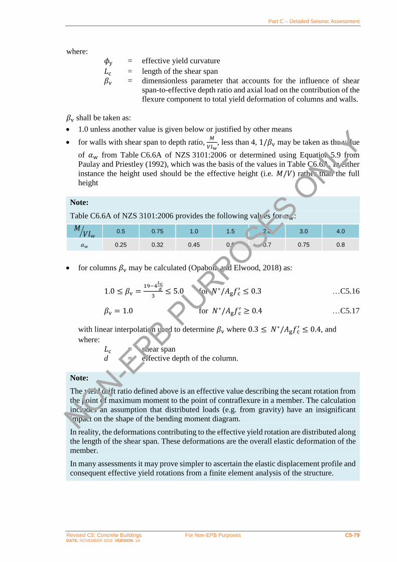
Part C – Detailed Seismic Assessment
Revised C5: Concrete Buildings For Non-EPB Purposes C5-79 DATE: NOVEMBER 2018 VERSION: 1A
where:
𝜙y = effective yield curvature
𝐿c = length of the shear span
𝛽v = dimensionless parameter that accounts for the influence of shear
span-to-effective depth ratio and axial load on the contribution of the
flexure component to total yield deformation of columns and walls.
𝛽v shall be taken as:
• 1.0 unless another value is given below or justified by other means
• for walls with shear span to depth ratio, 𝑀
𝑉𝑙w, less than 4, 1/𝛽v may be taken as the value
of 𝛼w from Table C6.6A of NZS 3101:2006 or determined using Equation 5.9 from
Paulay and Priestley (1992), which was the basis of the values in Table C6.6A. In either
instance the height used should be the effective height (i.e. 𝑀/𝑉) rather than the full
height
Note:
Table C6.6A of NZS 3101:2006 provides the following values for 𝛼w:
𝑀𝑉𝑙w
⁄ 0.5 0.75 1.0 1.5 2.0 3.0 4.0
𝛼w 0.25 0.32 0.45 0.6 0.7 0.75 0.8
• for columns 𝛽v may be calculated (Opabola and Elwood, 2018) as:
1.0 ≤ 𝛽v =19−4
𝐿c𝑑
3≤ 5.0 for 𝑁∗/𝐴g𝑓 c
′ ≤ 0.3 …C5.16
𝛽v = 1.0 for 𝑁∗/𝐴g𝑓 c′ ≥ 0.4 …C5.17
with linear interpolation used to determine 𝛽v where 0.3 ≤ 𝑁∗/𝐴g𝑓 c′ ≤ 0.4, and
where:
𝐿c = shear span
d = effective depth of the column.
Note:
The yield drift ratio defined above is an effective value describing the secant rotation from
the point of maximum moment to the point of contraflexure in a member. The calculation
includes an assumption that distributed loads (e.g. from gravity) have an insignificant
impact on the shape of the bending moment diagram.
In reality, the deformations contributing to the effective yield rotation are distributed along
the length of the shear span. These deformations are the overall elastic deformation of the
member.
In many assessments it may prove simpler to ascertain the elastic displacement profile and
consequent effective yield rotations from a finite element analysis of the structure.
NON-EPB P
URPOSES ONLY

Part C – Detailed Seismic Assessment
Revised C5: Concrete Buildings For Non-EPB Purposes C5-80 DATE: NOVEMBER 2018 VERSION: 1A
Ductile members
The effective yield curvature, 𝜙y, for a section containing a single layer of longitudinal
tension reinforcement that are able to develop their probable flexural capacity without other
failures occurring can be evaluated using a section analysis as:
𝜙y =𝜀y
𝑑−𝑐y …C5.18
where:
휀y = strain corresponding to the probable yield stress of the longitudinal
tension reinforcement
𝑑 = effective depth of the section
𝑐y = neutral axis depth when tension steel reaches the yield strain, 휀y.
Generally, the effective yield curvature, 𝜙y, should be defined using a bilinear
approximation (refer to Figure C5.11), particularly for members containing multiple layers
of longitudinal reinforcement. The yield curvature determined from a bilinear approximation
is referred to as the effective yield curvature.
Figure C5.11: Bilinear representation of moment-curvature relationship
Note:
The bilinear approximation of a moment-curvature relationship should be determined as
follows:
• The elastic response of the member is defined by a line extending from the origin and
passing through the point corresponding to first yield of reinforcement, i.e. yielding of
the outermost longitudinal reinforcing bars.
• The plastic response of the member is defined by a constant moment corresponding to
the probable moment capacity, 𝑀p.
• The effective yield curvature, 𝜙y, is determined as the curvature corresponding to the
intersection of the lines representing elastic and plastic response.
NON-EPB P
URPOSES ONLY

Part C – Detailed Seismic Assessment
Revised C5: Concrete Buildings For Non-EPB Purposes C5-81 DATE: NOVEMBER 2018 VERSION: 1A
Priestley and Kowalsky (2000) have shown that the effective yield curvature is largely
insensitive to the axial load and reinforcement ratio, and can be estimated:
• for rectangular-section beams and columns, as:
𝜙y =2.0 y
ℎb …C5.19
• for T-section beams, as:
𝜙y =1.7y
ℎb …C5.20
• for rectangular shear walls, as:
𝜙y =2y
𝑙w ...C5.21
• for flanged shear walls, as:
𝜙y =1.5y
𝑙w …C5.22
where:
ℎb = beam or column depth
𝑙w = wall length.
Non-ductile members
Non-ductile members are not able to develop their probable flexural capacity without other
behaviour such as shear failure or lap splice failure limiting their performance. The effective
yield curvature for non-ductile members can be calculated using the methods described in
the preceding section but replacing the reinforcement yield stress, 𝑓y, with the longitudinal
reinforcement stress, 𝑓s, corresponding to the occurrence of non-ductile behaviour.
Note:
In many cases where the members are unable to develop the yield stress of the longitudinal
reinforcement they contain, the yield rotation corresponds to the rotation capacity, 𝜃cap,
i.e. the inelastic rotation capacity of the member is equal to zero.
C5.5.3.2 Deformation limits due to member geometric effects
In certain scenarios both walls and columns can be susceptible to lateral
deformation/buckling over the length of a member between points of lateral restraint.
Appropriate limits on deformation capacity accounting for this behaviour are described in
the following sections.
NON-EPB P
URPOSES ONLY
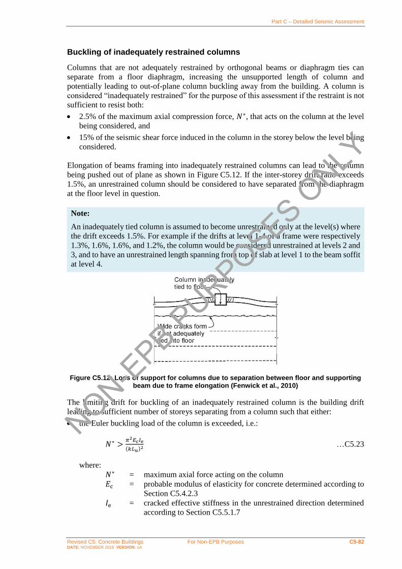
Part C – Detailed Seismic Assessment
Revised C5: Concrete Buildings For Non-EPB Purposes C5-82 DATE: NOVEMBER 2018 VERSION: 1A
Buckling of inadequately restrained columns
Columns that are not adequately restrained by orthogonal beams or diaphragm ties can
separate from a floor diaphragm, increasing the unsupported length of column and
potentially leading to out-of-plane column buckling away from the building. A column is
considered “inadequately restrained” for the purpose of this assessment if the restraint is not
sufficient to resist both:
• 2.5% of the maximum axial compression force, 𝑁∗, that acts on the column at the level
being considered, and
• 15% of the seismic shear force induced in the column in the storey below the level being
considered.
Elongation of beams framing into inadequately restrained columns can lead to the column
being pushed out of plane as shown in Figure C5.12. If the inter-storey drift ratio exceeds
1.5%, an unrestrained column should be considered to have separated from the diaphragm
at the floor level in question.
Note:
An inadequately tied column is assumed to become unrestrained only at the level(s) where
the drift exceeds 1.5%. For example if the drifts at level 1-4 of a frame were respectively
1.3%, 1.6%, 1.6%, and 1.2%, the column would be considered unrestrained at levels 2 and
3, and to have an unrestrained length spanning from top of slab at level 1 to the beam soffit
at level 4.
Figure C5.12: Loss of support for columns due to separation between floor and supporting beam due to frame elongation (Fenwick et al., 2010)
The limiting drift for buckling of an inadequately restrained column is the building drift
leading to sufficient number of storeys separating from a column such that either:
• the Euler buckling load of the column is exceeded, i.e.:
𝑁∗ >𝜋2𝐸c𝐼e
(𝑘𝐿u)2 …C5.23
where:
𝑁∗ = maximum axial force acting on the column
𝐸c = probable modulus of elasticity for concrete determined according to
Section C5.4.2.3
𝐼e = cracked effective stiffness in the unrestrained direction determined
according to Section C5.5.1.7
NON-EPB P
URPOSES ONLY

Part C – Detailed Seismic Assessment
Revised C5: Concrete Buildings For Non-EPB Purposes C5-83 DATE: NOVEMBER 2018 VERSION: 1A
𝑘 = Effective length factor that shall be taken as 1.0 unless a lower value
can be justified based on the provisions of NZS 3101:2006 or other
suitable reference. Notwithstanding other calculations, 𝑘 shall not be
taken as less than 1.0 unless it can be shown based on capacity design
principles that plastic hinges cannot form in the unrestrained length
of the column
𝐿u = Unrestrained length in the out-of-plane direction, taken as the clear
distance between floor slabs, beams, or other members capable of
providing lateral support for that column or pier, in the direction
being considered and accounting for separations from the diaphragm
or
• the column slenderness ratio exceeds 100, i.e.:
𝑘𝐿u
𝑟> 100 …C5.24
where 𝑘 and 𝐿u are as defined above, and
𝑟 = column radius of gyration, taken equal to 0.30 times the overall
dimension in the direction stability is being considered for a
rectangular column, and 0.25 times the diameter for a circular
column. For other shapes, r shall be computed for the gross concrete
section.
Note:
NZS 3101:2006 Clause 10.3.6 provides requirements for the restraint of columns at each
diaphragm level. Similar requirements were also included in NZS 3101:1995
Clause 4.3.6.7. Older buildings were not required to provide this level of restraint for
exterior columns not supported by a perpendicular beam and may be vulnerable to
movement out of plane due to elongation of the in-plane beam hinges. This is particularly
critical for buildings without starter bars attaching the exterior beam to the diaphragm.
Even when starters are present, for columns in a frame parallel to the precast units, the
engineer should check possible splitting at the junction between units where only mesh is
present.
Matthews (2004) showed that elongation of beams can lead to out of plane movement of
an unsupported column and tearing of the diaphragm mesh at 1.9% drift. Considering
variability in performance and bidirectional actions in a real building, this drift is rounded
down to 1.5% drift at which tearing of the diaphragm can be expected.
Out of plane (lateral) instability of walls
For all walls the probable inelastic rotation capacity shall not be taken as larger than the
rotation predicted to cause out-of-plane instability of the wall.
Out-of-plane (or lateral) instability can cause failure of slender rectangular RC walls. This
mode of failure, which involves buckling of a large portion of a wall element as opposed to
the ‘local’ bar buckling phenomenon where a single bar is affected, was previously observed
in experimental studies of rectangular walls. Appendix C5F provides an overview of the
issue and a description of current knowledge on the topic.
NON-EPB P
URPOSES ONLY

Part C – Detailed Seismic Assessment
Revised C5: Concrete Buildings For Non-EPB Purposes C5-84 DATE: NOVEMBER 2018 VERSION: 1A
The approach developed by Oliver et al. (2012) based on the work of Paulay and Priestley
(1993) has been adapted for use here. On this basis, the probable rotation capacity at the
onset of wall lateral instability shall be calculated as:
𝜃p =2𝜀y
𝑙w𝐿p,w (
40𝑏c2𝐸s𝛽w𝜉c
7𝐿o2𝑓y
− 1) …C5.25
where:
휀y = reinforcement yield strain but shall not be taken as greater than
0.0002.
𝑙w = wall length
𝐿p,w = wall effective plastic hinge length
= 0.15 (𝑀
𝑉) ≤ 0.5𝑙w where
𝑀
𝑉 is the moment to shear force ratio
𝑏c = effective thickness of wall boundary element within plastic hinge
region
𝐸s = elastic modulus of reinforcing steel, taken as 200,000 MPa
𝑓y = yield stress of wall longitudinal reinforcement
𝛽w = wall effective width factor
= 0.8 for doubly reinforced walls
= 0.5 for singly reinforced walls
𝜉c = normalised critical out-of-plane displacement
= 0.5 + 1.18𝑚 − √1.38𝑚2 + 1.18𝑚 …C5.26
𝐿o = critical buckling length of wall
= 0.2𝑙w + 0.044ℎw ≤ 0.8ℎn …C5.27
where:
ℎw = total height of the wall above the critical section of the plastic
hinge
ℎn = clear height to the next floor above the critical section
𝑚 = mechanical reinforcement ratio of the wall end region
= 𝜌ℓ𝑓y
𝑓 c′ …C5.28
where:
𝜌ℓ = longitudinal reinforcement ratio in the end region of the wall.
For walls without flanges or boundary elements, the effective thickness of the boundary
region, 𝑏c, shall be taken as the wall web width, 𝑏w. For walls with boundary elements or
flanges:
𝑏c = minimum of √𝐴wb or 10𝐴wb
𝑙w, but not less than 𝑏w …C5.29
where:
𝐴wb = area of the wall boundary element.
NON-EPB P
URPOSES ONLY

Part C – Detailed Seismic Assessment
Revised C5: Concrete Buildings For Non-EPB Purposes C5-85 DATE: NOVEMBER 2018 VERSION: 1A
C5.5.3.3 Probable rotation capacity - direct rotation method
An alternative to calculating the inelastic rotation capacity based on moment-curvature
analysis is to determine appropriate values from experimental testing of reinforced concrete
elements.
The applicability of experimentally-derived rotation capacities is limited to the element
configurations included in the database of experiments used to derive the capacities. Care is
required to ensure that the parameters of members being assessed fit within the bounds
specified for the capacities. For example, rotation capacities derived from tests on planar
walls may not be applicable for determination of the rotation capacity of an L-shaped wall.
An advantage of the direct rotation method is that factors such as bar buckling and concrete
spalling are implicitly accounted for, provided the underlying dataset sufficiently captures
such phenomena.
The direct rotation approach follows the approach implemented in typical U.S. practice
(ASCE 41-17, 2017).
Note:
The use of experimentally derived data to determine deformation capacities has been
introduced as an alternative to the moment-curvature approach used in previous versions
of these guidelines as the traditional approach may not able to capture shear deformations
which can be significant in poorly detailed reinforced concrete members. The use of
experimentally data to determine deformation capacities also results in more accurate
estimates of the likely failure mechanism and ultimate rotation capacity of the member
(Opabola and Elwood, 2018).
Rotation limits for beams, columns, and walls of various configurations are described in the
following sections.
The rotation capacities specified in this section for elements containing deformed
longitudinal bars are generally only applicable where distributed cracking is expected to
occur in accordance with Section C5.5.1.6. If distributed cracking is not expected to occur,
then the rotation capacity should not be taken as greater than that calculated based on the
single-crack plastic hinge length and appropriate strain limits defined in Section C5.5.3.4.
The rotation capacities specified in this section for elements containing plain longitudinal
bars are applicable to all such elements irrespective of the expected distribution of cracking.
Probable rotation capacity of beams
The probable rotation capacity of beams depends on the reinforcement detailing they
contain, and on whether plain or longitudinal bars are used for the longitudinal
reinforcement.
In all cases the probable yield rotation can be calculated using the procedures described in
Section C5.5.3.1.
NON-EPB P
URPOSES ONLY

Part C – Detailed Seismic Assessment
Revised C5: Concrete Buildings For Non-EPB Purposes C5-86 DATE: NOVEMBER 2018 VERSION: 1A
Beams reinforced with deformed bars
For beams the equivalent inelastic rotation capacity, 𝜃p, can be determined from Table C5.7,
where:
𝜌 = ratio of tension reinforcement area, 𝐴s, including effective flange
reinforcement to web area, = 𝐴s/𝑏w𝑑
𝜌′ = ratio of compression reinforcement area, 𝐴 s′ , including effective
flange reinforcement to web area, = 𝐴 s′ /𝑏w𝑑
𝜌bal = ratio of area of reinforcement corresponding to balanced strain
conditions, 𝐴s,bal, to web area, = 𝐴s,bal/𝑏w𝑑
𝑉∗ = design shear force
𝑏w = beam web width
𝑑 = beam effective depth
𝑓 c′ = probable concrete compressive strength.
Table C5.7: Probable inelastic rotation capacity for beams reinforced with deformed bars
that do not comply with the limited ductile or ductile detailing requirements of
NZS 3101:2006 (ASCE 41-17, 2017)
Probable Failure Mechanismb Probable inelastic rotation
capacity, 𝜽𝐩, (radians)a
Beams controlled by flexure:
(𝜌 − 𝜌′
𝜌bal)
𝑉∗
𝑏w𝑑√𝑓′c
≤ 0.0 0.25 0.020
≤ 0.0 0.50 0.010
≥ 0.5 0.25 0.010
≥ 0.5 0.50 0.005
Beams controlled by shear 0.003
Beams controlled by inadequate development or splicing along length
0.003
Beams controlled by inadequate embedment into beam-column joint 0.015
Note:
1. Values between those listed in the table shall be determined by linear interpolation.
2. Where more than one failure mechanism might apply the minimum elastic rotation capacity shall be used.
Note:
The equivalent inelastic rotation capacities detailed in Table C5.7 have been derived from
ASCE 41-17 (2017) with the ASCE 41-17 ‘a’ modelling parameter adopted.
For beams that comply with the limited ductile or ductile detailing requirements of
NZS 3101:2006 the probable inelastic rotation capacity, 𝜃p, can be determined as follows,
but need not be taken as less than the value determined from Table C5.7:
𝜃p = (𝐾d − 1)2𝜀y
ℎb𝐿p,b …C5.30
NON-EPB P
URPOSES ONLY

Part C – Detailed Seismic Assessment
Revised C5: Concrete Buildings For Non-EPB Purposes C5-87 DATE: NOVEMBER 2018 VERSION: 1A
where:
𝐾d = limiting material strain factor
= 11 for beams that comply with the limited ductile detailing
requirements of NZS 3101:2006
= 19 for beams that comply with the ductile detailing requirements of
NZS 3101:2006
휀y = reinforcement yield strain, but shall not be taken as greater than
0.0002.
ℎb = beam depth
𝐿p,b = beam effective plastic hinge length.
For the purpose of determining the equivalent inelastic rotation capacity of a beam with
reversing plastic hinges the effective plastic hinge length, 𝐿p,b, shall be evaluated as:
0.25𝑘pℎb ≤ 𝐿p,b = 0.25𝑘p (𝑀
𝑉) ≤ 0.5𝑘pℎb …C5.31
where:
𝑀/𝑉 = the moment to shear force ratio
ℎb = height of the beam
𝑘p = plastic hinge section parameter
= (ℎb
𝑑− 0.25) ≥ 1.0 …C5.32
where 𝑑 is the effective depth longitudinal tension reinforcement.
For beams with unidirectional plastic hinges, where inelastic rotation can develop on both
sides of the critical section, the effective plastic hinge length, 𝐿p,b , can be taken as twice
that calculated using Equation C5.31 above.
Beams reinforced with plain round bars
The probable rotation capacity of beams reinforced with plain longitudinal bars that are
adequately spliced or developed using hooks as described in Section C5.5.2.2, can be
assessed using Table C5.7.
Beams reinforced with plain longitudinal bars with inadequate lap splices shall be considered
to be brittle and have no inelastic rotation capacity.
Probable rotation capacity of columns
The inelastic rotation capacity for columns shall be calculated based on the appropriate
procedure below depending on whether the columns have:
• deformed longitudinal reinforcement that is not controlled by inadequate development
or splicing along the clear height
• deformed longitudinal reinforcement that is controlled by inadequate development or
splicing along the clear height, or
• plain longitudinal reinforcement, whether or not controlled by inadequate development
or splicing.
NON-EPB P
URPOSES ONLY

Part C – Detailed Seismic Assessment
Revised C5: Concrete Buildings For Non-EPB Purposes C5-88 DATE: NOVEMBER 2018 VERSION: 1A
Columns are considered to be controlled by inadequate development or splicing if the stress
developed in the column longitudinal reinforcement at any point in the span of the column
exceeds the lap/splice stress limit calculated using Equations C5.6 and C5.7.
In all cases, the probable yield rotation can be calculated using the procedures described in
Section C5.5.3.1.
Note:
When determining the probable rotation capacity of columns, it is important to keep in
mind the limitation as imposed by Equation C5.8 as discussed on page C5-64 that the
probable drift capacity, Δcap/𝐿c, shall not be taken as greater than two-thirds of the drift
ratio at onset of loss of gravity load carrying capacity, Δf/𝐿c. The drift ratio at onset of
loss of gravity load carrying capacity, Δf/𝐿c, can be determined using procedures outlined
in Section C5.5.4.
Columns with deformed bars not controlled by inadequate splices
For columns with an axial load ratio, 𝑁∗
𝐴g𝑓 c′ , exceeding 0.5, the inelastic rotation capacity, 𝜃p,
shall be taken as zero.
For columns not controlled by inadequate development or splicing along the clear height the
equivalent inelastic rotation capacity, 𝜃p, can be determined (Opabola and Elwood, 2018)
as:
𝜃p = 0.031 − 0.032𝑁∗
𝐴g𝑓 c′ + 0.47𝜌t − 0.017
𝑉y
𝑉p,col0≥ 0.0 …C5.33
where:
𝐴g = gross section area of column
𝑓 c′ = probable concrete compression strength
𝑁∗ = axial load accounting for the effects of seismic loads 𝑁∗
𝐴g𝑓 c′ = column axial load ratio, not to be taken as less than 0.1 for this
calculation
𝑉y = column shear demand associated with the development of the
probable flexural capacity of the plastic hinges at the top and bottom
of the column
𝑉p,col0 = undegraded probable shear capacity of the column calculated using
the procedures in Section C5.5.5.2.
𝜌t = transverse reinforcement ratio. 𝜌t shall not be taken greater than
0.0175 in any case, nor greater than 0.0075 when ties are not
adequately anchored into the core. The equation is not valid for 𝜌t
less than 0.0005.
The shear ratio, 𝑉y/𝑉p,col0, shall not be taken less than 0.2. The column shear demand 𝑉y
should be calculated assuming that the probable yield stress of the reinforcement can be
developed at the top and bottom of the column irrespective of whether anchorage and/or
splice lengths are found to be inadequate.
NON-EPB P
URPOSES ONLY

Part C – Detailed Seismic Assessment
Revised C5: Concrete Buildings For Non-EPB Purposes C5-89 DATE: NOVEMBER 2018 VERSION: 1A
The transverse reinforcement ratio, 𝜌t, can be calculated for rectangular columns as:
𝜌t =𝐴v
𝑏c𝑠 …C5.34
where:
𝐴v = area of transverse shear reinforcement within spacing, 𝑠
𝑏c = column dimension perpendicular to the direction of the shear
𝑠 = spacing of transverse shear reinforcement.
Note:
Columns shall be considered shear controlled when the inelastic rotation capacity, 𝜃p,
calculated using Equation C5.33 is less than or equal to zero. In this instance the probable
capacity of the column will be equal to the undegraded shear capacity of the column,
𝑉p,col0, and the probable rotation capacity will be equal to the yield rotation.
Columns with deformed bars controlled by inadequate splices
The inelastic rotation capacity, 𝜃p, for columns controlled by inadequate development or
splicing shall be taken as zero if the splice region is not crossed by at least two tie groups
over the length of the splice.
Otherwise, for columns controlled by inadequate development or splicing along their clear
height where the inadequate splice is confined by at least two stirrup sets along its length the
equivalent inelastic rotation capacity, 𝜃p, can be evaluated as (ASCE 41-17, 2017):
𝜃p =1
10
𝜌t
𝜌ℓ
𝑓yt
𝑓y{
≥ 0.0≤ 0.02
…C5.35
where:
𝑓yt = probable yield strength of transverse reinforcement
𝜌ℓ = longitudinal reinforcement ratio
𝜌t = transverse reinforcement ratio.
Notwithstanding the above, neither the equivalent inelastic rotation capacity, 𝜃p, nor
inelastic rotation at the onset of axial failure, 𝜃f, for columns controlled by inadequate
development or splicing along their clear height shall be taken greater than the equivalent
value applicable to columns not controlled by inadequate development or splicing.
Note:
Equations C5.33 and C5.35 have been derived from ASCE 41-17 (2017). When deriving
the equations a soft conversion factor of 0.75 has been applied to the ASCE 41-17 (2017)
‘a’ modelling parameter.
Columns with plain bars
Columns with 𝑉y
𝑉p,col0≥ 1.0 are vulnerable to shear failure and should be assessed using the
previously presented provisions for columns with deformed bars.
NON-EPB P
URPOSES ONLY

Part C – Detailed Seismic Assessment
Revised C5: Concrete Buildings For Non-EPB Purposes C5-90 DATE: NOVEMBER 2018 VERSION: 1A
Otherwise, the probable inelastic rotation capacity of columns with plain bars for
longitudinal reinforcement and axial load ratio, 𝑁∗
𝐴g𝑓 c′, less than or equal to 0.3 is defined as
equal to the equivalent post-yield rocking capacity, 𝜃r:
𝜃p = 𝜃r …C5.36
For columns with an axial load ratio, 𝑁∗
𝐴g𝑓 c′ , exceeding 0.5, the probable rocking capacity, 𝜃r,
shall be taken as zero. Linear interpolation shall be used where the axial load ratio is between
0.3 and 0.5. The axial load used to determine the rocking capacity should not be taken as
less than 0.0.
The probable rocking capacity, 𝜃r, is defined as the inelastic rotation corresponding to the
onset of significant loss in lateral strength. The probable rocking capacity, 𝜃r, can be
determined as follows:
𝜃r = 0.2𝑘r𝛼 …C5.37
where:
𝛼 = angle of the diagonal compression strut to the longitudinal axis of
the column as illustrated in Figure C5.13
𝑘r = coefficient that accounts for the effect of shear span-to-effective
depth ratio on deformation capacity
= 0.1 for 𝐿c
𝑑≤ 1
= 2.0 for 𝐿c
𝑑≥ 5
with linear interpolation used where 1.0 <𝐿c
𝑑< 5.
Note:
Other than where pre-emptive shear failure is expected to occur, Equation C5.37 is
intended to apply to all concrete columns reinforced with plain longitudinal bars, including
those columns which have lap splices. Data from experimental testing has demonstrated
seismic performance is governed by bond degradation which starts to occur at, or close to,
the yield strain of the longitudinal bars.
NON-EPB P
URPOSES ONLY

Part C – Detailed Seismic Assessment
Revised C5: Concrete Buildings For Non-EPB Purposes C5-91 DATE: NOVEMBER 2018 VERSION: 1A
(a) Reverse Bending (b) Single Bending
Figure C5.13: Column compression strut angle, 𝜶 ,(adapted from Priestley et al., 1996)
Probable rotation capacity of walls
Structural walls or wall segments shall not be considered effective at resisting seismic loads
where the axial load sustained by the wall is greater than 0.35𝑁p,max, where:
𝑁p,max = α1𝑓 c′(𝐴g − 𝐴st) + 𝑓y𝐴st …C5.38
where:
𝛼1 = rectangular stress block parameter calculated according to
NZS 3101:2006 as 𝛼1 = 0.85 − 0.004(𝑓 c′ − 55) ≥ 0.75
𝑓 c′ = probable concrete compressive strength
𝐴g = gross area of section
𝐴st = Total area of longitudinal reinforcing steel
𝑓y = probable yield strength of longitudinal reinforcing steel.
Where a wall or wall segment has a horizontal reinforcement ratio, 𝜌h, less than 0.0015 the
inelastic rotation capacity, 𝜃p, shall be taken as zero.
The deformation capacity of walls considered effective at resisting seismic loads can be
determined based on the method from the appropriate sections below. These sections provide
limits for walls having:
• plain longitudinal reinforcement
• slender walls (shear span to depth ratio greater than 2) with deformed longitudinal
reinforcement, and
• squat walls (shear span to depth ratio less than 2) with deformed longitudinal
reinforcement.
c/2
N* (axial load)
a
N*
c/2
Vn
Vn
N*cosa
a
N*cosa
N*
c/2
Vn
N* (axial load)
Vn
Lc
Lc
d d
hc hc
NON-EPB P
URPOSES ONLY

Part C – Detailed Seismic Assessment
Revised C5: Concrete Buildings For Non-EPB Purposes C5-92 DATE: NOVEMBER 2018 VERSION: 1A
Splice lengths for longitudinal reinforcement should be evaluated using the procedures
detailed in Section C5.5.2.2. Reduced flexural strengths shall be evaluated at locations where
splices govern the useable stress in the longitudinal reinforcement.
Irrespective of the wall detailing, the inelastic rotation capacity shall not be taken as greater
than the deformation corresponding to the onset of out-of-plane instability as defined in
Section C5.5.3.2.
Walls with plain reinforcement
The probable inelastic rotation capacity of walls with plain bars for longitudinal
reinforcement is taken as equal to the equivalent post-yield rocking capacity, 𝜃r:
𝜃p = 𝜃r …C5.39
but not greater than the probable rotation capacity that would be calculated if the
reinforcement was assumed to be deformed.
The probable rocking capacity, 𝜃r, is defined as the inelastic rotation corresponding to the
onset of significant loss in lateral strength. The probable rocking capacity, 𝜃r, can be
determined as follows:
𝜃r = 0.2𝑘r𝛼 …C5.40
where:
𝛼 = angle of the diagonal compression strut to the longitudinal axis of
the wall as illustrated in Figure C5.13
𝑘r = coefficient that accounts for the effect of shear span-to-effective
depth ratio on deformation capacity
= 0.1 for 𝐿c
𝑑≤ 1
= 2.0 for 𝐿c
𝑑≥ 5
with linear interpolation used where 1 <𝐿c
𝑑< 5.
Slender walls with deformed longitudinal reinforcement
Slender walls are those that have shear span to depth ratio, 𝑀
𝑉𝑙w, greater than or equal to 2.
Walls with shear span ratios greater than or equal to 2 may have their inelastic behaviour
controlled by shear or flexure. In cases where flexure is found to control, the probable
inelastic rotation capacity, (𝜃p), of walls with shear span to depth ratios greater than or equal
to 2.0 can be determined (Shegay et al., 2018) as:
𝜃p = (𝐾d − 1)𝜙y𝐿p …C5.41
where:
𝜙y = the probable yield curvature determined in accordance with
Section C5.5.3.1 as 𝜙y =2y
𝑙w
𝐾d = curvature ductility index calculated as outlined below
NON-EPB P
URPOSES ONLY

Part C – Detailed Seismic Assessment
Revised C5: Concrete Buildings For Non-EPB Purposes C5-93 DATE: NOVEMBER 2018 VERSION: 1A
휀y = reinforcement yield strain but shall not be taken as greater than
0.0002.
𝑙w = wall length
𝐿p = wall effective plastic hinge length
= 𝑘. 𝐿c + 0.1𝑙w + 𝐿 sp
𝐿sp = strain penetration = 0.022𝑓y𝑑b
𝑘 = 0.2 (𝑓u
𝑓y− 1) ≤ 0.08
𝐿c = distance from the critical section to the point of contraflexure.
The curvature ductility capacity, 𝐾d, shall be determined as (Crowe, 2018):
𝐾d = 15 − 20𝑐
𝑙w …C5.42
where:
𝑐 = neutral axis depth corresponding to the development of the probable
moment capacity
For walls complying with the ductile detailing requirements of NZS 3101:2006, 𝐾d need not
be taken as less than the value calculated using Equation C5.42, but may be determined as
(Shegay et al 2018):
𝐾d = min {
0.009
𝜀y(𝑐
𝐿w)
𝐾d_max
…C5.43
where:
𝐾d_max = 22 for 𝑠/𝑑b ≤ 4
= 12 for 𝑠/𝑑b ≥ 5 and linearly interpolated in between.
When determining if a wall complies with the detailing requirements of NZS 3101:2006 the
following shall be acceptable:
• confirmation that distributed cracking is expected to occur in accordance with
Section C5.5.1.6 may be used in lieu of compliance with the longitudinal reinforcement
limits of NZS 3101:2006
• wall lateral stability may be checked on the basis outlined in Section C5.5.3.2 in lieu of
compliance with the wall dimensional limits of NZS 3101:2006, and
• splices in the wall shall be deemed acceptable provided they are sufficient to develop the
yield strength of the reinforcement in accordance with Equation C5.6.
Squat walls
Squat walls are those with shear span to depth ratio, 𝑀
𝑉𝑙w, less than 2.
If the axial load ratio, 𝑁∗
𝐴g𝑓 c′ , exceeds 0.15 the probable inelastic rotation capacity of walls
with shear span ratios less than 2.0 shall be taken as equal to zero.
NON-EPB P
URPOSES ONLY

Part C – Detailed Seismic Assessment
Revised C5: Concrete Buildings For Non-EPB Purposes C5-94 DATE: NOVEMBER 2018 VERSION: 1A
Walls with shear span to depth ratios 1 ≤𝑀
𝑉𝑙w< 2 that comply with the limited ductile or
ductile detailing requirements of NZS 3101:2006 to the extent described in the previous
section on slender walls, may have their inelastic deformation capacity determined according
to the procedures for slender walls, but need not have their drift capacity taken as less than
the values determined from the equations in this section for squat walls.
When the axial load ratio, 𝑁∗
𝐴g𝑓 c′ , is less than 0.15 the probable deformation capacity of walls
with shear span ratios less than 2.0 is:
Δcap
𝐿c= 0.01 when
(𝐴s− 𝐴′s)𝑓y+𝑁∗
𝑡w𝑙w𝑓 c′ ≤ 0.05 …C5.44
Δcap
𝐿c= 0.0075 when
(𝐴s− 𝐴′s)𝑓y+𝑁∗
𝑡w𝑙w𝑓 c′ > 0.05 …C5.45
where:
𝐴s = area of non-prestressed tension reinforcement
𝐴′s = area of compression reinforcement
𝑓y = the probable yield strength of the longitudinal reinforcement
𝑁∗ = axial load
𝑡w = wall thickness
𝑙w = wall length.
Walls with shear span to depth ratio 𝑀
𝑉< 2.0 are assumed to have their inelastic response
controlled by shear.
Note:
Shear dominated interconnected walls (i.e. shear cores) with axial load ratios, 𝑁∗
𝐴g𝑓 c′ , greater
than 0.15 may constitute a SSW. As described in Part C1, categorisation as a SSW depends
on whether more than 60% of the lateral demand on the building is required to be resisted
by such shear dominated walls.
Probable rotation capacity of coupling beams
The probable rotation capacity of coupling beams depends on whether they are diagonally
reinforcement or conventionally reinforced, i.e. have longitudinal reinforcement parallel to
the longitudinal axis of the beam. In both cases, the probable rotation capacity is defined as
the equivalent chord rotation as illustrated in Figure C5.14. NON-EPB P
URPOSES ONLY

Part C – Detailed Seismic Assessment
Revised C5: Concrete Buildings For Non-EPB Purposes C5-95 DATE: NOVEMBER 2018 VERSION: 1A
Figure C5.14: Rotation definition for a coupling beam
In order to be effective, the longitudinal and/or diagonal reinforcement must be adequately
anchored into the walls coupled by the beam. The adequacy of development shall be
confirmed using the procedures described in Section C5.4.4 along with verification by the
strut-and-tie method (Section C5.6.1) that load paths exist to transfer the anchored forces
into the wall.
Note:
Failure of coupling beams is not likely to cause a significant hazard to life safety.
Notwithstanding this point, it is important to assess the capacity of coupling beams
because the overall flexibility (and consequently drift demand) is likely to be significantly
increased if coupling between walls becomes ineffective.
Diagonally reinforced coupling beams
For diagonally reinforced coupling beams that comply with the reinforcement detailing
specified in Clauses 11.4.9.3 and 11.4.9.4 of NZS 3101:2006, the probable deformation
capacity shall be taken as Δcap
𝐿c= 0.035.
For other diagonally reinforced coupling beams, the probable deformation capacity shall be
taken as Δcap
𝐿c= 0.03.
Conventionally reinforced coupling beams
The probable deformation capacity, Δcap
𝐿c, of conventionally reinforced coupling beams shall
be determined from either Table C5.8 if the beam is controlled by flexural behaviour or
Table C5.9 if controlled by shear, where:
𝑉y = shear force corresponding to development of probable flexural
strength at either end of the coupling beam
𝑉p,cb = coupling beam probable shear strength calculated according to
Section C5.5.5.1
𝑏w = beam web width
𝑑 = beam effective depth
𝑓 c′ = probable concrete compressive strength.
NON-EPB P
URPOSES ONLY

Part C – Detailed Seismic Assessment
Revised C5: Concrete Buildings For Non-EPB Purposes C5-96 DATE: NOVEMBER 2018 VERSION: 1A
Coupling beams can be considered shear controlled when the shear ratio 𝑉y/𝑉p,cb is greater
than or equal to one. Coupling beams can be considered flexural or flexure-shear controlled
when the shear ratio 𝑉y/𝑉p,cb is less one. The probable coupling beam shear strength, 𝑉p,cb,
can conservatively be calculated using the procedures for beams described in
Section C5.5.5.1
Alternatively, the inelastic rotation capacity, 𝜃p,of conventionally reinforced coupling
beams that comply with the limited ductile or ductile detailing provisions of NZS 3101:2006
may be assessed using Equation C5.30.
Table C5.8: Probable deformation capacities, 𝚫𝐜𝐚𝐩
𝑳𝐜, for conventionally reinforced coupling
beams with behaviour controlled by flexure
Shear stress ratio Stirrup spacing 𝒔 ≤ 𝒅/𝟑 and
𝑽𝐬 ≥ 𝟎. 𝟕𝟓𝑽𝐲
Stirrup spacing 𝒔 > 𝒅/𝟑 or
𝑽𝐬 ≥ 𝟎. 𝟕𝟓𝑽𝐲
𝑉y
𝑏w𝑑√𝒇 𝐜′
≤ 0.25 𝑀𝑃𝑎 0.025 0.020
0.25 <𝑉y
𝑏w𝑑√𝒇 𝐜′
< 0.5 0.03 − 0.02𝑉𝑦
𝑏w𝑑√𝒇 𝐜′ 0.03 − 0.04
𝑉y
𝑏w𝑑√𝒇 𝐜′
≥ 0.5 MPa 0.020 0.010
Note:
For coupling beams with clear span ≤ 2.5 m, with bottom reinforcement continuous into the supporting walls, the
probable rotation capacities shall be permitted to be doubled.
Table C5.9: Probable rotation capacities, 𝚫𝐜𝐚𝐩
𝑳𝐜, for conventionally reinforced coupling beams
with behaviour controlled by shear
Shear stress ratio, 𝑽𝐩,𝐜𝐛
𝒃𝐰𝒅√𝒇 𝐜′
Stirrup spacing 𝒔 ≤ 𝒅/𝟑 and
𝑽𝐬 ≥ 𝟎. 𝟕𝟓𝑽𝐲
Stirrup spacing 𝒔 > 𝒅/𝟑 or
𝑽𝐬 ≥ 𝟎. 𝟕𝟓𝑽𝐲
𝑉p,cb
𝑏w𝑑√𝒇 𝐜′
≤ 0.25 𝑀𝑃𝑎 0.020 0.012
0.25 <𝑉p,cb
𝑏w𝑑√𝒇 𝐜′
< 0.5 0.024 − 0.016𝑉p,cb
𝑏w𝑑√𝒇 𝐜′ 0.016 − 0.016
𝑉p,cb
𝑏w𝑑√𝒇 𝐜′
𝑉p,cb
𝑏w𝑑√𝒇 𝐜′
≥ 0.5 𝑀𝑃𝑎 0.016 0.008
Note:
For coupling beams with clear span ≤ 2.5 m, with bottom reinforcement continuous into the supporting walls, the
probable rotation capacities shall be permitted to be doubled.
Note:
The deformation capacities summarised in Tables C5.8 and C5.9 are adopted from
ASCE 41-17 (2017).
NON-EPB P
URPOSES ONLY
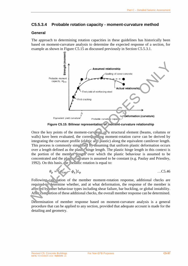
Part C – Detailed Seismic Assessment
Revised C5: Concrete Buildings For Non-EPB Purposes C5-97 DATE: NOVEMBER 2018 VERSION: 1A
C5.5.3.4 Probable rotation capacity - moment-curvature method
General
The approach to determining rotation capacities in these guidelines has historically been
based on moment-curvature analysis to determine the expected response of a section, for
example as shown in Figure C5.15 as discussed previously in Section C5.5.3.1.
Figure C5.15: Bilinear representation of moment-curvature relationship
Once the key points of the moment-curvature of a structural element (beams, columns or
walls) have been evaluated, the corresponding moment-rotation curve can be derived by
integrating the curvature profile (elastic and plastic) along the equivalent cantilever length.
This process is commonly simplified by assuming that uniform plastic deformation occurs
over a length defined as the plastic hinge length. The plastic hinge length in this context is
the portion of the member length over which the plastic behaviour is assumed to be
concentrated and the plastic curvature is assumed to be constant (e.g. Paulay and Priestley,
1992). On this basis, the inelastic rotation is equal to:
𝜃p = (𝜙cap − 𝜙y)𝐿p …C5.46
Following calculation of the member moment-rotation response, additional checks are
required to determine whether, and at what deformation, the response of the member is
affected by other behaviour types including shear failure, bar buckling, or global instability.
After completion of these additional checks, the overall member response can be determined.
Determination of member response based on moment-curvature analysis is a general
procedure that can be applied to any section, provided that adequate account is made for the
detailing and geometry.
NON-EPB P
URPOSES ONLY

Part C – Detailed Seismic Assessment
Revised C5: Concrete Buildings For Non-EPB Purposes C5-98 DATE: NOVEMBER 2018 VERSION: 1A
Plastic hinge length
The equivalent plastic hinge length is the length over which a constant plastic deformation
is assumed to occur. The appropriate length depends on whether the reinforcement content
and detailing of a member is sufficient to ensure distributed cracking (and consequently
distributed plastic deformation) occurs.
Plastic hinge length where distributed cracking is expected
Where distributed cracking is expected to occur in accordance with Section C5.5.1.6, the
equivalent plastic hinge length, 𝐿p, may be calculated (Priestley et al., 2007) as:
𝐿p = 𝑘lp𝐿c + 𝐿sp ≥ 2𝐿sp …C5.47
where:
𝑘lp = 0.2 (𝑓u
𝑓y− 1) ≤ 0.08 …C5.48
𝐿c = distance of the critical section from the point of contraflexure
𝐿sp = strain penetration = 0.022𝑓y𝑑b
𝑓y = probable yield strength of longitudinal reinforcement
𝑑b = diameter of longitudinal reinforcement
𝑓u = probable ultimate strength of the longitudinal reinforcement.
The first term, 𝑘lp𝐿c, represents the spread of plasticity due to tension-shift effects and the
second term, 𝐿sp, represents the strain penetration into the supporting member (e.g. beam-
column joint). The lower limit reflects the fact that plasticity is expected to spread over at
least twice the strain penetration length.
As suggested by Priestley et al. (2007), the plastic hinge length of shear walls is more likely
to be influenced by tension shift effects than is the case with beams or columns. Therefore,
when compared to the expression for plastic hinge length in beams and columns, an
additional term in the plastic hinge equation should be included as a function of the wall
length as follows:
𝐿P = 𝑘. 𝐿c + 0.1𝑙w + 𝐿sp ...C5.49
𝑘 = 0.2 (𝑓u
𝑓y− 1) ≤ 0.08 ...C5.50
𝐿sp = 0.022𝑓y𝑑b ...C5.51
where:
𝐿c = distance from the critical section to the point of the contraflexure
𝑙w = wall length.
Note:
The values presented above for the evaluation of the plastic hinge length are typically
based on experimental results with reference to relatively well detailed plastic hinge
regions and use of deformed bars.
NON-EPB P
URPOSES ONLY
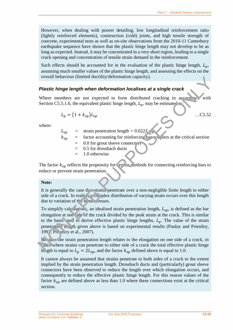
Part C – Detailed Seismic Assessment
Revised C5: Concrete Buildings For Non-EPB Purposes C5-99 DATE: NOVEMBER 2018 VERSION: 1A
However, when dealing with poorer detailing, low longitudinal reinforcement ratio
(lightly reinforced elements), construction (cold) joints, and high tensile strength of
concrete, experimental tests as well as on-site observations from the 2010-11 Canterbury
earthquake sequence have shown that the plastic hinge length may not develop to be as
long as expected. Instead, it may be concentrated in a very short region, leading to a single
crack opening and concentration of tensile strain demand in the reinforcement.
Such effects should be accounted for in the evaluation of the plastic hinge length, 𝐿p,
assuming much smaller values of the plastic hinge length, and assessing the effects on the
overall behaviour (limited ductility/deformation capacity).
Plastic hinge length when deformation localises at a single crack
Where members are not expected to form distributed cracking in accordance with
Section C5.5.1.6, the equivalent plastic hinge length, 𝐿p, may be estimated as:
𝐿p = (1 + 𝑘sp)𝐿sp …C5.52
where:
𝐿sp = strain penetration length = 0.022𝑓y𝑑b
𝑘sp = factor accounting for reinforcing bar couplers at the critical section
= 0.0 for grout sleeve connectors
= 0.5 for drossbach ducts
= 1.0 otherwise.
The factor 𝑘sp reflects the propensity for certain methods for connecting reinforcing bars to
reduce or prevent strain penetration.
Note:
It is generally the case that strains penetrate over a non-negligible finite length to either
side of a crack. In reality, a complex distribution of varying strain occurs over this length
due to variation of the bond stresses.
To simplify calculations, an idealised strain penetration length, 𝐿sp, is defined as the bar
elongation at one side of the crack divided by the peak strain at the crack. This is similar
to the basis used to derive effective plastic hinge lengths, 𝐿p. The value of the strain
penetration length given above is based on experimental results (Paulay and Priestley,
1992; Priestley et al., 2007).
Because the strain penetration length relates to the elongation on one side of a crack, in
cases where strains can penetrate to either side of a crack the total effective plastic hinge
length is equal to 𝐿p = 2𝐿sp, and the factor 𝑘sp defined above is equal to 1.0.
It cannot always be assumed that strains penetrate to both sides of a crack to the extent
implied by the strain penetration length. Drossbach ducts and (particularly) grout sleeve
connectors have been observed to reduce the length over which elongation occurs, and
consequently to reduce the effective plastic hinge length. For this reason values of the
factor 𝑘sp are defined above as less than 1.0 where these connections exist at the critical
section.
NON-EPB P
URPOSES ONLY

Part C – Detailed Seismic Assessment
Revised C5: Concrete Buildings For Non-EPB Purposes C5-100 DATE: NOVEMBER 2018 VERSION: 1A
Probable curvature capacity, 𝝓𝐜𝐚𝐩
The probable curvature capacity for a beam, column, or wall can be taken as the lesser of:
𝜙cap =c,max
𝑐prob …C5.53
and:
𝜙cap =s,max
𝑑−𝑐prob …C5.54
where:
𝑐prob = neutral axis depth at probable capacity
c,max = the accepted maximum concrete compressive strain, at the extreme
fibre of the section or of the confined core region, depending on the
extent of confinement of the concrete (as defined in Table C5.10 and
further explained below)
s,max = the maximum accepted strain of the reinforcing steel in tension (as
defined in Table C5.10)
𝑑 = effective depth of longitudinal tension reinforcement.
Table C5.10: Concrete and steel strain limits for calculation of probable curvature capacity
Material Strain limit
Unconfined concrete (including cover concrete)
휀c,max = 0.004
Concrete surrounding unconfined drossbach ducts1
휀c,max = 0.002
Confined concrete 휀c,max = 0.004 +
0.6𝜌st𝑓yh휀su
𝑓′cc≤ 0.05
where: 𝜌st = volumetric ratio of confinement reinforcement
=0.75𝐴v,d
𝑏core𝑠+
0.75𝐴v,b
𝑑core𝑠 for beams and columns
𝑓yh = yield strength of the confinement reinforcement
휀su = strain at the tensile strength of the reinforcing steel
𝑓′cc = compression strength of the confined concrete
𝐴v,d = area of confinement reinforcement parallel to the depth of
the section that crosses the compression block within a depth 𝑠
𝐴v,b = total area of confinement reinforcement parallel to the
breadth of the section that crosses the compression block within depth 𝑠
𝑠 = spacing of layers of confinement reinforcement
𝑏core = width of core measured from centre to centre of the peripheral transverse reinforcement
𝑑core = depth of core measured from centre to centre of the peripheral transverse reinforcement
Steel 휀s,max = 0.6휀su ≤ 0.06
where: 휀su = strain at the tensile strength of the reinforcing steel
Note:
1. Drossbach ducts may be considered confined if the duct is crossed over its length by at least three tie groups that
would be deemed able to provide effective confinement to core concrete.
NON-EPB P
URPOSES ONLY
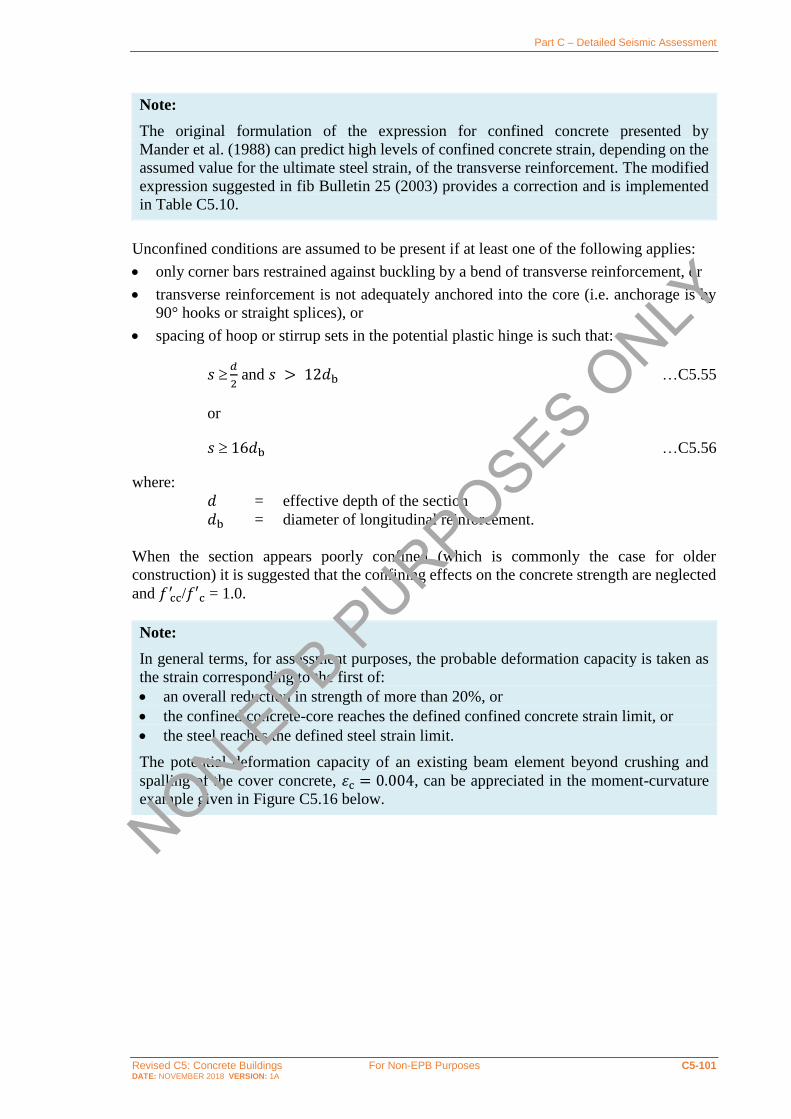
Part C – Detailed Seismic Assessment
Revised C5: Concrete Buildings For Non-EPB Purposes C5-101 DATE: NOVEMBER 2018 VERSION: 1A
Note:
The original formulation of the expression for confined concrete presented by
Mander et al. (1988) can predict high levels of confined concrete strain, depending on the
assumed value for the ultimate steel strain, of the transverse reinforcement. The modified
expression suggested in fib Bulletin 25 (2003) provides a correction and is implemented
in Table C5.10.
Unconfined conditions are assumed to be present if at least one of the following applies:
• only corner bars restrained against buckling by a bend of transverse reinforcement, or
• transverse reinforcement is not adequately anchored into the core (i.e. anchorage is by
90° hooks or straight splices), or
• spacing of hoop or stirrup sets in the potential plastic hinge is such that:
𝑠 𝑑
2 and 𝑠 > 12𝑑b …C5.55
or
𝑠 16𝑑b …C5.56
where:
𝑑 = effective depth of the section
𝑑b = diameter of longitudinal reinforcement.
When the section appears poorly confined (which is commonly the case for older
construction) it is suggested that the confining effects on the concrete strength are neglected
and 𝑓 cc′ /𝑓′c = 1.0.
Note:
In general terms, for assessment purposes, the probable deformation capacity is taken as
the strain corresponding to the first of:
• an overall reduction in strength of more than 20%, or
• the confined concrete-core reaches the defined confined concrete strain limit, or
• the steel reaches the defined steel strain limit.
The potential deformation capacity of an existing beam element beyond crushing and
spalling of the cover concrete, 휀c = 0.004, can be appreciated in the moment-curvature
example given in Figure C5.16 below.
NON-EPB P
URPOSES ONLY

Part C – Detailed Seismic Assessment
Revised C5: Concrete Buildings For Non-EPB Purposes C5-102 DATE: NOVEMBER 2018 VERSION: 1A
Figure C5.16: Example of a moment-curvature curve for a flanged (T or L) beam
Note:
Moment-curvature analyses will show that, while the yield curvature is not greatly
affected by axial load level (particularly when yield curvature is expressed in terms of
equivalent elasto-plastic response), the curvature capacity is strongly dependent on axial
load.
This is illustrated in Figure C5.17 further below, where a poorly confined (transverse
reinforcement D10@400, 2 legs only) end column of a frame with nominal axial load of
𝑁∗ = 0.2𝑓′c𝐴g is subjected to seismic axial force variations of 𝑁∗E = 0.2𝑓′c𝐴g. The yield
curvatures differ by less than 10% from the mean, while the ultimate curvatures at 𝑁∗ = 0
and 𝑁∗ = 0.4𝑓′c𝐴g are 61% and 263% of the value at 𝑁∗ = 0.2𝑓′c𝐴g.
On the other hand, especially in columns with high axial load ratios, poor confinement
detailing and large cover concrete, the loss of cover concrete (resulting from or combined
with buckling of the longitudinal rebars) can correspond to the onset of full loss of axial
load capacity refer below.
In general terms, the evaluation of ultimate curvature for walls can be carried out in a
similar manner to that presented for columns. Special care should be taken in relation to
the particular mechanisms of wall elements.
The main hypothesis of ‘plane sections remain plane’, i.e. linear strain profile along the
wall section length, 𝑙w, might not be valid at the probable moment capacity due to higher
concentration of strains in both tension and compression area. Therefore, a traditional
section analysis approach may lead to unconservative results and overestimate the
curvature/rotation/displacement demand of walls.
However, while acknowledging the limitations of section analysis, it can still be a valuable
approach to determine an upper bound of the deformation capacity of an existing wall
under an ideal flexurally dominated behaviour.
NON-EPB P
URPOSES ONLY

Part C – Detailed Seismic Assessment
Revised C5: Concrete Buildings For Non-EPB Purposes C5-103 DATE: NOVEMBER 2018 VERSION: 1A
Interaction with shear (either before or after yielding), local bar buckling or out-of-plane
(lateral global) instability can lead to premature failure. More information on these failure
mechanisms are described in the following sections and in Appendix C5F.
Figure C5.17: Example of a moment-curvature response of a column with poor confinement
Buckling of reinforcing steel in columns and walls
When the spacing of the transverse reinforcement restraining buckling of the vertical
reinforcement in a wall or column is greater than 6𝑑b, cyclic loading and strains in the
vertical reinforcing bars greater than yield are expected, the probable curvature capacity of
the wall or column section should be limited (Alvarado et al., 2015) to:
𝜙cap =𝜀p
∗
𝛾𝑙w ...C5.57
and:
0.02 ≤ 휀p∗ =
11−(s/𝑑b)
150≤ 0.06 ...C5.58
where:
휀p∗ = experimentally observed buckling strain
𝛾𝑙w = length between outermost layers of reinforcement as shown in
Figure C5.18
𝑠 = spacing of transverse reinforcement
𝑑b = diameter of reinforcing bars in the outer layers of longitudinal
reinforcement.
NON-EPB P
URPOSES ONLY

Part C – Detailed Seismic Assessment
Revised C5: Concrete Buildings For Non-EPB Purposes C5-104 DATE: NOVEMBER 2018 VERSION: 1A
Figure C5.18: Definition of 𝜸𝒍𝐰 according to Rodriguez et al. (2013)
Note:
Buckling of reinforcing bars in RC elements is a complex phenomenon and, although
design standards contain general detailing requirements to postpone or avoid this, there is
currently limited information for assessing existing buildings. Appendix C5F discusses
buckling of reinforcing bars in walls in some detail.
C5.5.4 Deformation at onset of loss of gravity load capacity
For certain items, it may be acceptable to exceed the probable deformation capacity, Δcap
𝐿c,
provided gravity load capacity is not compromised and other elements in the structure can
maintain lateral stability of the structure. Approaches for determining the deformation
capacity at onset of loss of gravity load capacity are defined in this section for columns and
slab-column connections.
Note:
In many scenarios it is not acceptable for elements to exceed their probable deformation
capacity, Δcap
𝐿c.
Such exceedance may be acceptable in scenarios where the lateral stability of the structure
does not require the contribution of the element being considered and reliable (diaphragm)
load paths exist that can redistribute lateral forces to other elements of the building.
Examples where this may occur include:
• slender columns acting in parallel with walls that can resist the lateral demands placed
on a structure
• columns in secondary frames acting in parallel with primary frames that can resist the
lateral demands on a structure, or
• slab-column systems acting in parallel with walls or moment resisting frames that
resist the lateral demands on a structure.
At the date of publication, methods are in development for estimating the drift ratio at loss
of gravity load carry capacity for walls but are not yet available for implementation in
these guidelines.
NON-EPB P
URPOSES ONLY

Part C – Detailed Seismic Assessment
Revised C5: Concrete Buildings For Non-EPB Purposes C5-105 DATE: NOVEMBER 2018 VERSION: 1A
C5.5.4.1 Columns with deformed bars not controlled by inadequate splices
For columns not controlled by inadequate development or splicing, the equivalent inelastic
rotation capacity at the onset of axial failure, 𝜃a, can be calculated as (ASCE 41-17, 2017):
𝜃a =0.25
5+𝑁∗
0.8𝐴g𝑓 c′
1
𝜌t 𝑓 c
′
𝑓yt
− 0.005 ≥ 𝜃p …C5.59
where: 𝑁∗
𝐴g𝑓 c′ = column axial load ratio, not to be taken as less than 0.1 for this
calculation
𝐴g = gross section area of column
𝑓 c′ = probable concrete compression strength
𝑁∗ = axial load accounting for the effects of seismic loads
𝑓yt = yield strength of the column transverse reinforcement
𝜌t = transverse reinforcement ratio. 𝜌t shall not be taken greater than
0.0175 in any case, nor greater than 0.0075 when ties are not
adequately anchored into the core. The equation is not valid for 𝜌t
less than 0.0005.
The equation above is valid when 𝑁
𝐴g𝑓 c′ ≤ 0.50. When
𝑁
𝐴g𝑓 c′ ≥ 0.70 the inelastic rotation at
the onset of axial failure shall be as taken as 𝜃f = 0.0, with linear interpolation used where
0.5 <𝑁
𝐴g𝑓 c′ < 0.70.
Note:
The inelastic rotation capacity at onset of axial failure, 𝜃a, is defined above as 0.5 times
the ‘b’ value defined in ASCE 41-17 (2017). The ‘b’ value is approximately a median
value, which in ASCE 41-17 (2017) is multiplied by 0.7 to obtain approximately a lower
characteristic value suitable as a ‘CP’ (collapse prevention) acceptance criterion. Here the
‘CP’ value is further reduced to ensure a margin of performance exists for the element
beyond the ULS (design basis) demands used as the basis for these guidelines.
Column axial failure can be a SSW as defined in Chapter C1. The deformation capacity
of non-ductile reinforced concrete columns susceptible to axial failure should be taken as
one half of the probable lateral drift capacity determined in accordance with
equations above.
C5.5.4.2 Columns with deformed bars controlled by inadequate splices
For columns controlled by inadequate development or splicing, the equivalent inelastic
rotation capacity at the onset of axial failure, 𝜃a, can be calculated as (ASCE 41-17, 2017):
𝜃a = (0.006 − 0.043𝑁∗
𝐴g𝑓 c′ + 6𝜌t)
≥ 𝜃p
≤ 0.03 …C5.60
NON-EPB P
URPOSES ONLY

Part C – Detailed Seismic Assessment
Revised C5: Concrete Buildings For Non-EPB Purposes C5-106 DATE: NOVEMBER 2018 VERSION: 1A
where: 𝑁∗
𝐴g𝑓 c′ = column axial load ratio, not to be taken as less than 0.1 for this
calculation
𝐴g = gross section area of column
𝑓 c′ = probable concrete compression strength
𝑁∗ = axial load accounting for the effects of seismic loads
𝜌t = transverse reinforcement ratio. 𝜌t shall not be taken greater than
0.0075 in any case. The equation is not valid for 𝜌t less than 0.0005.
The equation above is valid when 𝑁
𝐴g𝑓 c′ ≤ 0.50. When
𝑁
𝐴g𝑓 c′ ≥ 0.70 the inelastic rotation at
the onset of axial failure shall be as taken as 𝜃f = 0.0, with linear interpolation used where
0.5 <𝑁
𝐴g𝑓 c′ < 0.70.
Note:
The inelastic rotation capacity at onset of axial failure, 𝜃a, is defined above as 0.5 times
the ‘b’ value defined in ASCE 41-17 (2017). The ‘b’ value is approximately a median
value, which in ASCE 41-17 (2017) is multiplied by 0.7 to obtain approximately a lower
characteristic value suitable as a ‘CP’ (collapse prevention) performance criteria. Here the
‘CP’ value is further reduced to ensure a margin of performance exists for the element
beyond the ULS (design basis) demands used as the basis for these guidelines.
Column axial failure can be a SSW, as defined in Chapter C1. The deformation capacity
of non-ductile reinforced concrete columns susceptible to axial failure should be taken as
one half of the probable lateral drift capacity determined in accordance with
equations above.
C5.5.4.3 Columns with plain bars
For columns with plain bars that are not prone to pre-emptive shear failure, the equivalent
inelastic rotation capacity at the onset of axial failure, 𝜃a, can be taken as twice the probable
rotation capacity calculated in accordance with section C5.5.3.3.
C5.5.4.4 Walls
Walls subjected to a high axial load may be susceptible to sudden axial failure featuring
crushing and shifting in the out-of-plane direction across the length of the entire wall. This
behaviour is referred to as through-the-thickness crushing failure, where a diagonal failure
plane is developed through the thickness (Zhang et al. 2018). The walls that potentially fail
due to loss of axial load capacity can be identified as follows:
walls with any reinforcement configuration: when (𝐴𝑠−𝐴𝑠
′ )𝑓𝑦+𝑁∗
𝑡𝑤𝑙𝑤𝑓𝑐′ > 0.3
walls with 𝑠/𝑡𝑤 > 1: when 0.08 <(𝐴𝑠−𝐴𝑠
′ )𝑓𝑦+𝑁∗
𝑡𝑤𝑙𝑤𝑓𝑐′ ≪ 0.3
where:
𝐴𝑠 = area of non-prestressed tension reinforcement
𝐴′𝑠 = area of compression reinforcement
NON-EPB P
URPOSES ONLY

Part C – Detailed Seismic Assessment
Revised C5: Concrete Buildings For Non-EPB Purposes C5-107 DATE: NOVEMBER 2018 VERSION: 1A
𝑓𝑦 = probable yield strength of the longitudinal reinforcement
𝑓𝑐′ = probable concrete compression strength
𝑁∗ = axial load
𝑡𝑤 = wall thickness
𝑙𝑤 = wall length
𝑠 = vertical spacing of closed hoops or cross ties in the boundary area, 𝑠
shall be taken as infinite if no closed hoops or cross ties are placed
Note:
Through-the-thickness failure of walls is categorized as a severe structural weakness
(SSW). Walls exhibiting axial failure typically fail at same or slightly larger drift level
compared with walls suffering lateral load failure. Hence the inelastic rotation capacity
can be calculated using equations C5.38 and C5.39 as described in the section on slender
walls.
C5.5.4.5 Slab-column joints
The critical performance requirement for slab-column joints is for the gravity load capacity
to be retained even after being subjected to numerous lateral displacement cycles. Slab-
column connections are susceptible to progressive collapse if punching shear failure occurs
at a connection, which is a particular risk for slabs with discontinuous bottom reinforcement
or lightly reinforced slabs. Many such failures have occurred in past earthquakes resulting
in significant loss of life.
It is generally appropriate to assume that slab-column joints are pinned for analysis purposes
and do not contribute to the stiffness of the structure.
The assessment procedure for slab-column joints is as follows:
Step 1: Determine the critical perimeter for the slab-column joint in accordance with
NZS 3101:2006 and allowing for the influence of stud rails or other shear head
reinforcement as required.
Step 2: Calculate the shear strength at the critical perimeter, 𝑉p, in accordance with
NZS 3101:2006 but excluding strength reduction factors and using probable
material strengths in lieu of nominal properties.
Step 3: Assess the shear force, 𝑉 g∗, at the critical perimeter based on reduced gravity
demands consistent with the earthquake load combination.
Step 4: Determine the inelastic rotation at the onset of loss of gravity support, 𝜃a, from
Figure C5.19 depending on the shear demand ratio, 𝑉 g∗/𝑉p and whether the
bottom reinforcement is continuous through the column. The bottom
reinforcement shall be deemed discontinuous unless the area of effectively
continuous main bottom bars passing through the column cage in each direction
is greater than or equal to:
𝐴s,bottom =0.6𝑉 g
∗
𝑓y …C5.61
NON-EPB P
URPOSES ONLY

Part C – Detailed Seismic Assessment
Revised C5: Concrete Buildings For Non-EPB Purposes C5-108 DATE: NOVEMBER 2018 VERSION: 1A
Figure C5.19: Inelastic rotation at the onset of loss of gravity support, 𝜽𝐚, for slab-column connections
Note:
The inelastic rotation capacity at onset of axial failure, 𝜃a, is defined in Figure C5.19 as
approximately 0.7 times the ‘b’ value defined in ASCE 41-17 (2017). The ‘b’ value is
considered in ASCE 41-17 (2017) to be a value suitable as a ‘CP’ (collapse prevention)
performance criteria. Here the ‘CP’ value is reduced to ensure a margin of performance
exists for the element beyond the ULS (design basis) demands used as the basis for these
guidelines.
Punching shear failure of slab-column connections may be a SSW, as defined in Chapter
C1. Where the ratio of gravity shear demand to shear strength, 𝑉 g∗/𝑉p, exceeds 0.4 the
capacity of should be taken as one half of the probable lateral drift capacity
determined above.
C5.5.5 Probable shear capacity
Procedures are outlined in this section for evaluating the probable shear strength, 𝑉prob, of
beam, column, and wall elements. For each of these types of element the probable shear
strength is dependent on the plastic deformation imposed on the element, with the value
reducing from the ‘undegraded’ shear strength as the imposed plastic deformation increases.
Elements with undegraded shear strengths that are less than the shear demand associated
with development of the probable flexural strength of the element shall be assumed to be
controlled by shear.
Note:
Elements that are not controlled by shear may ultimately be controlled by flexure or by
flexure-shear interaction depending on whether shear degradation as plastic deformation
NON-EPB P
URPOSES ONLY

Part C – Detailed Seismic Assessment
Revised C5: Concrete Buildings For Non-EPB Purposes C5-109 DATE: NOVEMBER 2018 VERSION: 1A
increases causes the shear strength to drop below the shear demand required to sustain
flexural yielding.
For example, Figure C5.20 shows the force-deformation relationships for flexure and shear
for a column beam. The element is not controlled by shear as the undegraded shear
strength is greater than the shear demand resulting from flexural yielding. However, as
increasing plastic deformation causes shear degradation to occur, the shear strength drops
below the shear demand corresponding to flexural yielding indicating that the element is
controlled by flexure-shear interaction.
It should be understood that the probable rotation capacity of elements controlled by
flexure-shear interaction is defined by the intersection point of two curves that generally
approach each other at an acute angle. The calculation of this value is therefore sensitive
to the material properties and strength models used.
Where the direct rotation method (refer to Section C5.5.3.3) is used to determine the
rotation capacity of elements it will not generally be necessary to assess degradation of
shear strength as this phenomenon is considered implicitly in the experimental data used
to derive the rotation limits.
Figure C5.20: Example of the combined flexural-shear mechanisms within a force-displacement capacity curve for a column or beam (Stirrat et al., 2014)
C5.5.5.1 Beams and walls
The probable shear capacity of reinforced concrete beams and walls can be calculated as:
𝑉prob = 0.85(𝑉c+𝑉s + 𝑉n) …C5.62
where 𝑉c, 𝑉s and 𝑉n are the shear contributions provided by the concrete mechanism, steel
shear reinforcement and (where present) the axial compressive load respectively, as
described below.
Note:
The shear model described above and detailed in the following sections is adapted from
the ‘University of California San Diego’ model described by Priestley et al. (2007). The
model is further described for walls by Krolicki et al. (2011) and is based on model
proposed by Kowalsky and Priestley (2000) for the evaluation of the shear capacity of
columns.
Displacement
Late
ral
forc
e
Flexure
Shear
Bi-liniear approx.
Bar buckling
Shear failure
y
u
Fu
Fy
NON-EPB P
URPOSES ONLY

Part C – Detailed Seismic Assessment
Revised C5: Concrete Buildings For Non-EPB Purposes C5-110 DATE: NOVEMBER 2018 VERSION: 1A
Concrete contribution
The shear contribution from the concrete, 𝑉c, can be evaluated as:
𝑉c = 𝛼𝛽𝛾√𝑓′c(0.8𝐴g) …C5.63
where:
1 ≤ 𝛼 = 3 −𝑀
𝑉ℎ≤ 1.5
𝛽 = 0.5 + 20𝜌l ≤ 1
𝛾 = shear strength degradation factor (refer to Figure C5.21)
0.8𝐴g = effective shear area of the member section (not less than 𝑏w𝑑 for a
beam)
𝑏w = width of section web
𝑑 = effective depth of section
𝑀/𝑉 = ratio of moment to shear at the section
ℎ = total section depth or the beam or wall section as appropriate
𝜌l = ratio of the total area of the longitudinal reinforcement to the gross
area of the section, i.e. 𝐴st
𝐴g⁄ .
(a) Beams (b) Walls
Figure C5.21: Concrete shear strength degradation factor as a function of ductility: curvature ductility for beams and displacement ductility for walls
Note:
Where the rotation capacity of a beam or wall is assessed using the direct rotation method
(refer to Section C5.5.3.3) it is not necessary to consider the effects of shear degradation
outlined above as this effect is implicit in the experimental data used to calibrate the direct
rotation method.
Shear reinforcement contribution
The shear contribution from the shear reinforcing steel, 𝑉s, may be evaluated as follows.
0
0.05
0.1
0.15
0.2
0.25
0.3
0 2 4 6 8 10 12 14 16 18 20
She
ar
de
gra
da
tio
n f
act
or,
γ
Curvature ductility, μφ
(a) beams
Uniaxialdemand
Biaxialdemand
0
0.05
0.1
0.15
0.2
0.25
0.3
0 2 4 6 8
She
ar
de
gra
da
tio
n f
act
or,
γ
Displacement ductility, μΔ
(b) walls
NON-EPB P
URPOSES ONLY

Part C – Detailed Seismic Assessment
Revised C5: Concrete Buildings For Non-EPB Purposes C5-111 DATE: NOVEMBER 2018 VERSION: 1A
For beams it is assumed that the critical diagonal tension crack is inclined at 45° to the
longitudinal axis of the beam and the shear contribution is:
𝑉s =𝐴v𝑓yt𝑑
𝑠 …C5.64
where:
𝐴v = total effective area of hoops and cross ties in the direction of the
shear force at spacing 𝑠
𝑓yt = probable yield strength of the transverse reinforcement
𝑑 = effective depth of the beam.
For walls the shear contribution of the effective horizontal reinforcing steel, 𝑉s, may be
evaluated as follows:
𝑉s =𝐴v𝑓yhℎcr
s …C5.65
where:
ℎcr =𝑙′
tan 𝜃cr≤ ℎw …C5.66
𝑙′ = 𝑙w − 𝑐 − 𝑐0 …C5.67
𝜃cr = 45 − 7.5 (𝑀
𝑉𝑙w) ≥ 30° …C5.68
𝐴v = horizontal shear reinforcement
𝑓yh = yield strength of transverse reinforcement
𝑠 = centre-to-centre spacing of shear reinforcement along member
ℎw = wall height
𝑐 = the depth of the compression zone
𝑐0 = the cover to the longitudinal bars
𝑙w = wall length
𝑀/𝑉 = ratio of moment to shear at the section.
Axial force contribution
The shear resisted due to inclination of the compressive axial force 𝑁∗ is given by:
𝑉n = 𝑁∗ tan 𝛼 …C5.69
where:
𝛼 = the angle between the longitudinal axis of the member and the
straight line between the centroids of the concrete compressive
forces of the member section at the top and bottom of the column as
shown in Figure C5.22
𝑁∗ = axial compressive load, i.e. for this calculation 𝑁∗ ≥ 0.
NON-EPB P
URPOSES ONLY
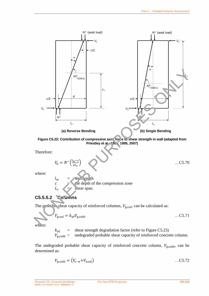
Part C – Detailed Seismic Assessment
Revised C5: Concrete Buildings For Non-EPB Purposes C5-112 DATE: NOVEMBER 2018 VERSION: 1A
(a) Reverse Bending (b) Single Bending
Figure C5.22: Contribution of compressive axial force to shear strength in wall (adapted from Priestley et al., 1994, 1995, 2007)
Therefore:
𝑉n = 𝑁∗ (𝑙w−𝑐
2𝐿c) …C5.70
where:
𝑙w = wall length
𝑐 = the depth of the compression zone
𝐿c = shear span.
C5.5.5.2 Columns
The probable shear capacity of reinforced columns, 𝑉p,col, can be calculated as:
𝑉p,col = 𝑘nl𝑉p,col0 …C5.71
where:
𝑘nl = shear strength degradation factor (refer to Figure C5.23)
𝑉p,col0 = undegraded probable shear capacity of reinforced concrete column.
The undegraded probable shear capacity of reinforced concrete column, 𝑉p,col0, can be
determined as:
𝑉p,col0 = (𝑉c−n+𝑉s,col) …C5.72
c/2
N* (axial load)
a
N*
c/2
Vn
Vn
N*cosa
a
N*cosa
N*
c/2
Vn
N* (axial load)
Vn
lw `
Lc
lw
Lc
d d
NON-EPB P
URPOSES ONLY

Part C – Detailed Seismic Assessment
Revised C5: Concrete Buildings For Non-EPB Purposes C5-113 DATE: NOVEMBER 2018 VERSION: 1A
where 𝑉c−n and 𝑉s,col are the shear contributions provided by the concrete mechanism
including the influence of axial compression force and steel shear reinforcement as described
below.
Figure C5.23: Concrete shear strength degradation factor as a function of rotation ductility for columns
Note:
The model proposed for column shear strength is adapted from Sezen and Moehle (2004)
and replaces the method previously used in these guidelines that was developed by
Kowalsky and Priestley (Priestley et al., 2007).
This change has been made because the Sezen and Moehle equations have been
demonstrated to be more accurate in predicting the shear capacity of columns (Del
Vecchio et al., 2017). Additionally, where the Kowalsky and Priestley shear equations are
based on a limited dataset consisting primarily of bridge columns, the Sezen and Moehle
shear equations are based on a larger data set that in addition to being broader is more
representative of the variety of columns encountered in existing buildings. The Sezen and
Moehle model has been adopted in ASCE 41-17 (2017). The UCSD model has been found
to be particularly non-conservative for columns that have rectangular cross sections and/or
slender aspect ratios (Del Vecchio et al., 2017)
In contrast to the shear strength of beams and walls, no reduction factor of 0.85 is applied
for columns. This is because the unadjusted equations are deemed to provide an
appropriate level of reliability (Del Vecchio et al., 2017).
In instances when using the direct rotation method, it will not be necessary to explicitly
determine the shear strength degradation factor, 𝑘nl. This is because the parameter is not
required to determine the ultimate rotation capacity for a (refer to Section C5.5.3.3)
The Sezen and Moehle model has been reformatted to match, to the extent possible the
format commonly used in New Zealand.
NON-EPB P
URPOSES ONLY

Part C – Detailed Seismic Assessment
Revised C5: Concrete Buildings For Non-EPB Purposes C5-114 DATE: NOVEMBER 2018 VERSION: 1A
Concrete contribution including the influence of axial force
The shear contribution provided by the concrete mechanism including the influence of axial
compression force, 𝑉c−n, can be calculated as:
𝑉c−n = (0.5√𝑓 c
′
𝑀∗
𝑉∗𝑑√1 +
𝑁∗G
0.5𝐴g√𝑓 c′) 0.8𝐴g …C5.73
where:
𝑓 c′ = probable concrete compression strength
𝑀∗ = column flexural demand accounting for the effects of seismic loads
𝑉∗ = column shear demand accounting for the effects of seismic loads
𝑑 = effective depth of column, taken as 0.8ℎc, where ℎc is the dimension
of the column in the direction of the shear 𝑀∗
𝑉∗𝑑 = largest moment to shear ratio anticipated for the column when
subjected to earthquake actions, but shall not be taken greater than 4
or less than 2
𝑁∗G = column axial force due to gravity actions only and taken as zero
where tension forces act on the column
𝐴g = gross area of column.
Shear reinforcement contribution
The shear contributions provided by the steel shear reinforcement, 𝑉s,col, can be calculated
as:
𝑉s,col = 𝛼v,col (𝐴v𝑓yt𝑑
𝑠) …C5.74
where:
𝛼v,col = dimensionless parameter for evaluating the effectiveness of
transverse reinforcement in resisting shear
𝐴v = effective area of transverse reinforcement parallel to the direction of
the shear within a spacing of 𝑠
𝑠 = spacing of transverse reinforcement
𝑑 = effective depth of column, taken as 0.8ℎc, where ℎc is the dimension
of the column in the direction of the shear
𝑓yt = probable yield strength of the transverse shear reinforcement.
The dimensionless parameter, 𝛼col, for evaluating the effectiveness of transverse
reinforcement in resisting shear can be determined as follows:
0 ≤ 𝛼v,col = 4 − 4𝑠
𝑑≤ 1.0 …C5.75
C5.5.5.3 Interface shear strength
In addition to conventional shear strength as discussed previously in this section, it will
commonly be necessary to check the interface shear strength (often referred to as sliding
NON-EPB P
URPOSES ONLY

Part C – Detailed Seismic Assessment
Revised C5: Concrete Buildings For Non-EPB Purposes C5-115 DATE: NOVEMBER 2018 VERSION: 1A
shear strength or shear friction) when assessing concrete structures, particularly where
substantial use has been made of precast concrete elements.
Where interface shear strength checks are required, these shall be undertaken in accordance
with clause 7.7 of NZS 3101:2006. Either the procedures described in the Standard itself or
the alternative procedures referenced in the commentary to Section 7.7 may be used. In either
case, probable material strengths may be used in lieu of nominal strengths and a factor of
0.85 used in lieu of the strength reduction factor.
NON-EPB P
URPOSES ONLY

Part C – Detailed Seismic Assessment
Revised C5: Concrete Buildings For Non-EPB Purposes C5-116 DATE: NOVEMBER 2018 VERSION: 1A
C5.6 Capacities of Diaphragms, Joints and Other Elements
C5.6.1 Strut-and-tie models
Strut-and-tie models will be necessary for the assessment of aspects of many concrete
structures. Where such models are required, they shall be developed in accordance
with Appendix A of NZS 3101:2006, or other relevant part of the New Zealand Concrete
Structures Standard.
The strength reduction factor, 𝜙, used for strut-and-tie models shall be in accordance with
the New Zealand Concrete Structures Standard, NZS 3101:2006. Thus:
• the strength reduction factor shall be taken as 𝜙 = 0.75, except in situations where
actions applied to the strut-and-tie model have been derived based on capacity design
principles;
• where actions applied to the strut-and-tie model have been derived based on capacity
design principles the strength reduction factor may be taken as 𝜙 = 1.0.
The capacity of struts and ties shall be calculated in accordance with the New Zealand
Concrete Structures Standard, except that probable material strengths may be used to
calculate capacities. Reduction factors 𝛽n for nodes and 𝛽s for struts should be taken as
specified in NZS 3101:2006.
Strut-and-tie models represent a plastic distribution of forces derived without explicit
verification of deformation compatibility. It is therefore of critical importance that the strain
capacity of ties is sufficient to sustain the postulated model. Reinforcement with probable
ultimate strain capacity less than 휀su ≤ 0.05 shall not be relied on when calculating the
probable capacity of ties.
C5.6.2 Beam-column joints
Provisions are provided in this section for calculating the probable strengths of beam-column
joints. Two approaches are provided, respectively focussed on:
• unreinforced, or lightly reinforced, joints, i.e. joints not containing any effective
transverse reinforcement in the joint core, or containing, in comparison to ‘modern’
beam-column joints, only a small amount of effective transverse reinforcement in the
joint core, and
• ‘modern’ beam-column joints, being joints containing transverse reinforcement
comparable to that which would be required today by NZS 3101:2006.
Note:
Modern beam-column joints will generally occur in correctly designed buildings
constructed after the introduction of NZS 3101:1982, albeit that poorly reinforced beam-
column joints may still be encountered in such buildings. Experience shows this to be the
case particularly for beam-column joints located in ‘secondary’ frames of buildings
designed according to NZS 3101:1982.
NON-EPB P
URPOSES ONLY

Part C – Detailed Seismic Assessment
Revised C5: Concrete Buildings For Non-EPB Purposes C5-117 DATE: NOVEMBER 2018 VERSION: 1A
C5.6.2.1 General
Several general aspects of beam-column joint behaviour are common to both methods for
assessing beam-column joint strength. These aspects are discussed in the following sections.
Beam-column joint configurations
As shown in Figure C5.24, various configurations of beam-column joint may commonly be
encountered depending on the position of the joint in a building, and whether the frames of
the building are one-way (typically perimeter) frames or two-way (uniform) frames.
Figure C5.24: Common beam-column joint configurations (Brooke, 2011)
Beam-column joint strength is highly dependent on whether the joint is an ‘interior’ joint
with beams framing into the joint from either side (Figures C5.24(c), C5.23(d) and
C5.24(e)), or an exterior joint with a beam framing in from one side only (Figures C5.24(a)
and C5.24(b). In some cases, a joint will be classified as an interior joint for loading on one
axis and an exterior joint for loading on the orthogonal axis (Figure C5.24(d)).
Effective joint reinforcement
Transverse reinforcement shall only be considered to contribute to the strength of a joint if
stirrups, hoops, spirals, or ties are terminated by hooks anchored in core concrete or, for
hoops, spirals, and stirrups, by welded closures. In most situations competent anchorage will
require the presence of 135° or 180° hooks.
Research has shown (Lin, 1999) that joint shear reinforcement close to the top and bottom
beam bars seldom yields. To account for this, the effective area of joint transverse
reinforcement should be determined based on the stress profile shown in Figure C5.25. This
profile assumes:
• shear reinforcement placed immediately adjacent to the top and bottom beam bars can
develop a stress equal to 0.4𝑓y
• yielding of shear reinforcement occurs in the central 60% of the depth of the joint
• the stress in reinforcement varies linearly across transient zones with a depth equal to
0.2ℎ" where ℎ" is the depth of the joint core measured between the centrelines of the
inner most beam longitudinal bars.
NON-EPB P
URPOSES ONLY

Part C – Detailed Seismic Assessment
Revised C5: Concrete Buildings For Non-EPB Purposes C5-118 DATE: NOVEMBER 2018 VERSION: 1A
Figure C5.25: Joint transverse reinforcement stress profile (Lin, 1999)
If shear reinforcement is distributed uniformly across the depth of the joint core, it can be
shown (Lin, 1999) that the effective area of reinforcement is:
𝐴jh,eff = 𝛼j𝐴jh = 0.88𝐴jh …C5.76
where:
𝐴jh,eff = area of joint shear reinforcement that effectively contributes to joint
strength
𝐴jh = total area of horizontal joint shear reinforcement parallel to the
direction being considered
𝛼j = coefficient relating the total and effective areas of joint transverse
reinforcement, equal to 0.88 where shear reinforcement is distributed
uniformly over the depth of the joint core.
Effective joint dimensions
The effective joint width, 𝑏j, shall be determined following the principals outlined in
NZS 3101:2006 and summarised in Figure C5.26.
For circular columns, the effective joint area may be taken as the area of the column provided
the diameter does not exceed the effective width defined in Figure C5.26.
NON-EPB P
URPOSES ONLY

Part C – Detailed Seismic Assessment
Revised C5: Concrete Buildings For Non-EPB Purposes C5-119 DATE: NOVEMBER 2018 VERSION: 1A
(a) (b)
Figure C5.26: Definition of effective joint width, 𝒃𝐣 (NZS 3101:2006)
C5.6.2.2 Probable strength of unreinforced or lightly reinforced beam-column joints
For interior and exterior beam-column joints without shear reinforcement, or with only
limited quantities of shear reinforcement, the probable horizontal joint shear strength, 𝑉jh is:
𝑉p,jh = 0.85𝑣jh𝑏jℎc ≤ 1.92√𝑓 c′𝑏jℎc …C5.77
where:
𝑣p,jh = probable horizontal joint shear stress capacity
𝑏j = effective width of the joint as defined in Section C5.6.2.1
ℎc = depth of column.
Note:
The factor of 0.85 has been included in the equation above to account for the higher
uncertainty (and impact) of a shear failure mechanism when compared to a flexural one.
The probable horizontal joint shear stress capacity shall be taken as the lesser of the probable
horizontal joint shear stress capacities resulting from exceedance of the principal tension
stress or principal compression stress, 𝑣jh,t and 𝑣jh,c respectively:
𝑣p,jh,t = √(𝑘j√𝑓 c′ )
2+ 𝑘j√𝑓 c
′ (𝑓v + 𝑓h) + 𝑓v𝑓h …C5.78
and
𝑣p,jh,c = √(0.6𝑓 c′ )2 − 0.6𝑓 c
′ (𝑓v + 𝑓h) + 𝑓v𝑓h …C5.79
where:
𝑓v = 𝑁∗
𝐴g is the effective axial load stress on the joint. (compressive stress
is taken as positive).
NON-EPB P
URPOSES ONLY

Part C – Detailed Seismic Assessment
Revised C5: Concrete Buildings For Non-EPB Purposes C5-120 DATE: NOVEMBER 2018 VERSION: 1A
𝑓h = 𝛼j𝐴jh𝑓yt
𝑏jℎb represents horizontal confinement effects due to the shear
reinforcement in the joint. 𝐴jh is the area of joint shear reinforcement
parallel to the direction being considered, 𝑓yt is the probable yield
strength of the joint shear reinforcement, and the effectiveness
factor, 𝛼j, can be determined as described in Section C5.6.2.1.
𝑘j = Coefficient for calculating the principal tension stress limit in a
beam-column joint calculated from Figure C5.27 depending on the
joint geometry and the curvature ductility demand developed in
members adjacent to the joint.
Figure C5.27: Joint shear coefficient, 𝒌𝐣, for different joint geometries
For joints with no effective shear reinforcement, the equations above simplify to:
𝑣p,jh,t = √(𝑘j√𝑓 c′ )
2+ 𝑘j√𝑓c
′ 𝑁∗
𝐴g …C5.80
and
𝑣p,jh,c = √(0.6𝑓 c′ )2 − 0.6𝑓 c
′ 𝑁∗
𝐴g …C5.81
Note:
The recommended values for 𝑘j are based on experimental testing by Hakuto et al.,
1995-2000, mostly focusing on deformed bars with no variation of axial load, and
Pampanin et al., 2000-2010, mostly focusing on plain bars and variation of axial load.
The equations were developed by assuming that the principal tensile strength, 𝑝t, of the
concrete was 𝑝t = 𝑘j√𝑓 c′ and the principal compression strength, 𝑝c, was 𝑝c = 0.6𝑓 c
′ and
using Mohr’s circle to calculate the horizontal shear stress required to induce these
Interior joint
Case 1
Case 2
Case 3
0
0.1
0.2
0.3
0.4
0.5
0.6
0.7
0.8
0.9
1
0 1 2 3 4 5 6 7 8 9 10
Join
t sh
ear
co
eff
icie
nt,
kj
Curvature ductility adjacent to the joint, μφ
Interior joint
Case 1
Case 2
Case 3
Exterior joints:
NON-EPB P
URPOSES ONLY

Part C – Detailed Seismic Assessment
Revised C5: Concrete Buildings For Non-EPB Purposes C5-121 DATE: NOVEMBER 2018 VERSION: 1A
principal stresses when the vertical compressive stress is 𝑁∗/𝐴g (Hakuto et al., 2000;
Pampanin et al., 2002).
Principal tensile stresses, 𝑝t, tend to govern the failure mechanism of exterior beam-
column joints, while principal compression stresses, 𝑝c, tend to govern interior beam-
column joints where higher levels of axial load are expected, and the damage/failure
mechanism is more correlated to the degradation of the diagonal compression strut.
as well as 𝑝t versus drift presented in literature and based on extensive experimental tests.
Based on strength degradation curves of tensile stress, 𝑝t, versus shear deformation, 𝛾,
(Pampanin et al., 2002, Celik and Ellingwood, 2008; Kam, 2011) indicative deformation
limits at ULS for beam-column joints with little or no shear reinforcement, expressed as
radians of shear deformation are as follows:
𝛾 = 0.01 for interior joints
= 0.007 for exterior joint, hooks bent into joint
= 0.0015 for exterior joint, hooks bent away from joint
= 0.001 for exterior joint, plain bars or 180° hooks.
Effects of bidirectional cyclic loading on joint capacity
Where beams frame into the joint from two directions, these forces need only be considered
in each direction independently.
In the absence of more detailed study or evidence, a reduction of 30% on the probable joint
shear strength shall be made when the joint is subjected to bidirectional loading.
Note:
The effects of bidirectional loading can significantly affect the response of poorly detailed
beam-column joints and modify the hierarchy of strength and sequence of events of the
sub-assembly – and thus possibly the overall global response of the frame.
Conceptually, the shear (or equivalent moment) strength reduction due to bidirectional
loading is similar to that expected in a column (both in flexure and shear) when subjected
to bidirectional loading.
Overlooking the effects of bidirectional loading on the local and global response and the
performance of an RC structure can significantly impair the efficiency of a retrofit
intervention.
Most studies on the seismic assessment and retrofit of existing poorly detailed frame
buildings have concentrated on the two-dimensional response, thus subjecting the
specimen or subassemblies to unidirectional cyclic loading testing protocols. Even when
the 3D response under combined bidirectional loading has been considered in
experimental testing, the focus has been typically on interior joints.
C5.6.2.3 Probable strength of well reinforced beam-column joints
The design of beam-column joints in New Zealand since the early 1980s has been based on
a conceptual model in which shear resistance arises from a combination of a central diagonal
compression strut resisted by the joint core concrete (refer to Figure C5.28(a)) and a truss
NON-EPB P
URPOSES ONLY

Part C – Detailed Seismic Assessment
Revised C5: Concrete Buildings For Non-EPB Purposes C5-122 DATE: NOVEMBER 2018 VERSION: 1A
mechanism (refer to Figure C5.28(b)) relying on joint shear reinforcement (Cheung et al.,
1992; Paulay and Priestley, 1992; NZS 3101:2006). The methods described here for
assessment of well reinforced beam-column joints are based on a similar conceptual model,
with different approaches required for interior joints (Lin, 1999; Lin and Restrepo, 2002)
and exterior joints (Cheung, 1991; NZS 3101:2006).
(a) Diagonal concrete strut (b) Truss mechanism
Figure C5.28: Joint shear mechanisms underpinning New Zealand approaches to design of beam-column joints
New Zealand practice (NZS 3101:2006) requires calculations to be undertaken to confirm
the ability of intermediate column longitudinal reinforcement to function as vertical joint
shear reinforcement. Such calculations are not deemed necessary for assessment purposes.
Research (Lin and Restrepo, 2002) has shown that the presence of vertical joint shear
reinforcement does not have significant influence on the joint strength provided that
horizontal joint shear reinforcement is present. Notwithstanding this observation,
intermediate column bars play an important role in ‘clamping’ the beam longitudinal
reinforcement and enhancing their anchorage in the joint core. The performance of a joint
not having interior column bars may be poor because of premature bond failure.
Note:
The joint shear strength model developed by Lin (1999; Lin and Restrepo, 2002) has been
adopted for assessment of interior joints instead of adaption of the design procedure used
in NZS 3101:2006 because it was developed more recently and has been shown to more
realistically predict the shear strength of joints. In contrast to the NZS 3101:2006 model,
the Lin model:
• acknowledges that even poorly reinforced beam-column joints can resist appreciable
shear forces
• accounts explicitly for the relationship between joint shear strength and plastic
deformation demands adjacent to the joint, and
• has been shown by other researchers to provide acceptable predictions of shear
strength for joints with a range of characteristics (Lehman et al., 2002; Mosier, 2000;
Walker, 2001).
NON-EPB P
URPOSES ONLY

Part C – Detailed Seismic Assessment
Revised C5: Concrete Buildings For Non-EPB Purposes C5-123 DATE: NOVEMBER 2018 VERSION: 1A
The Lin model has not been validated for exterior beam-column joints. Hence the design
procedure used in NZS 3101:2006 (Cheung et al., 1992; Paulay and Priestley, 1992;
NZS 3101:2006) has been adapted for assessment of exterior joints.
Effects of bidirectional cyclic loading on joint capacity
For both methods interior and exterior joints where beams frame into the joint from two
directions, these forces need only be considered in each direction independently.
Following the rationale adopted in New Zealand design (Paulay and Priestley, 1992;
NZS 3101:2006) it is convenient to consider that two truss mechanisms act simultaneously
and orthogonally to each other. However, it cannot be assumed that the concrete strut
mechanism is fully effective in both directions simultaneously. In the absence of more
detailed study or evidence, the probable strength of the strut mechanism in joints subjected
to bidirectional loading shall be multiplied (NZS 3101:2006) by:
𝐶j =𝑉jh
𝑉jh+𝑉jh,tr …C5.82
where:
𝑉jh = Horizontal joint shear force in the direction being considered
𝑉jh,tr = Horizontal joint shear force in the direction transverse to the
considered direction.
Note:
Bidirectional loading is not addressed by Lin (1999; Lin and Restrepo, 2002) in the
derivation of the model used here for interior joints. The factor 𝐶j has been added to the
derivation in a manner that is conceptually consistent with other New Zealand design
approaches.
Interior joints
The strength of interior joints can be determined using the method proposed by Lin and
Restrepo (2002; Lin, 1999) based on strut-and-tie analysis of the joint core. Two approaches
are available:
• The first provides a method for calculating the ‘lower bound’ joint strength, i.e. the joint
strength that can be sustained even when significant plastic deformation occurs in hinges
immediately adjacent to the joint.
• The second provides a method for calculating the joint strength depending on the
adjacent plastic deformation demands, which may be appropriate where (i) detailing
precludes formation of plastic hinges adjacent the joint or (ii) where other parts of the
structure (such as walls) limit the deformations expected to occur.
Strength of joint adjacent to large plastic deformations
For interior beam-column joints adjacent to plastic hinges sustaining any magnitude of
plastic deformation, the probable horizontal joint shear strength is:
𝑉p,jh = 0.85(𝑣cj + 𝑣jn + 𝑣sh) 𝑏jℎc ≤ 0.25𝑓 c′𝑏jℎc …C5.83
NON-EPB P
URPOSES ONLY

Part C – Detailed Seismic Assessment
Revised C5: Concrete Buildings For Non-EPB Purposes C5-124 DATE: NOVEMBER 2018 VERSION: 1A
where:
𝑣p,jh = probable horizontal joint shear stress capacity
𝑣cj = basic strut contribution to joint shear strength in the absence of
column axial load
𝑣jn = contribution of column axial load to the concrete strut contribution to
joint shear strength
𝑣sh = contribution of joint shear reinforcement to joint shear strength
𝑏j = effective width of the joint as defined in Section C5.6.2.1
ℎc = depth of column.
Note:
If the design joint shear force, 𝑉 jh∗ , is derived assuming the overstrength moment develops
in adjacent plastic hinges then the 0.85 factor may be removed from the equation above.
The basic strut contribution to joint shear strength in the absence of column axial load, 𝑣cj,
can be calculated as:
𝑣cj =𝑣 jh
∗
660(𝑣jh
∗
𝑓 c′ )
3 𝐶j …C5.84
where:
𝑣 jh∗ = joint shear stress demand =
𝑉 jh∗
𝑏jℎc where 𝑉 jh
∗ is the assessed joint shear
force
𝐶j = bidirectional loading factor.
The contribution of column axial load to the concrete strut contribution to joint shear
strength, 𝑣jn, shall be calculated depending on the column axial force ratio, 𝑁∗
𝐴g𝑓 c′ , as:
𝑣jn = 0 when 𝑁∗
𝐴g𝑓 c′ ≤ 0.1 …C5.85
𝑣jn = 1.6 (𝑁∗
𝐴g𝑓 c′ − 0.1) 𝑣 jh
∗ 𝐶j when 0.1 <𝑁∗
𝐴g𝑓 c′ ≤ 0.3 …C5.86
𝑣jn = (1 − 2.27𝑁∗
𝐴g𝑓 c′) 𝑣 jh
∗ 𝐶j when 0.3 <𝑁∗
𝐴g𝑓 c′ …C5.87
where:
𝑣 jh∗ = joint shear stress demand =
𝑉 jh∗
𝑏jℎc where 𝑉 jh
∗ is the assessed joint shear
force
𝐶j = bidirectional loading factor.
NON-EPB P
URPOSES ONLY

Part C – Detailed Seismic Assessment
Revised C5: Concrete Buildings For Non-EPB Purposes C5-125 DATE: NOVEMBER 2018 VERSION: 1A
The contribution of joint shear reinforcement to joint shear strength, 𝑣sh, shall be calculated
as:
𝑣sh =𝛼j𝐴jh𝑓yt
𝑏jℎb …C5.88
where:
𝛼j = 0.88 unless a larger effectiveness factor, 𝛼j ≤ 1.0, can be justified
based on Section C5.6.2.1
𝐴jh = area of joint shear reinforcement parallel to the direction being
considered
𝑓yt = probable yield strength of the joint shear reinforcement, and the
effectiveness factor.
Note:
Lin (1999) found that, in contrast to the implication of New Zealand design requirements,
joint shear strength does not necessarily increase with increasing column axial force. Lin
found that the quantity of joint shear reinforcement required decreased as the column axial
force ratio, 𝑁∗
𝐴g𝑓 c′ , increased from 0.1 to 0.3, but then increased again if the column axial
force ratio exceeded 0.3. These findings are reflected in the equations above.
Strength of joint dependent on adjacent plastic deformation
Lin (1999) describes a method for extending the method described in the previous section to
allow calculation of magnitude of inelastic deformation demand occurring in plastic hinges
adjacent to the joint that can be sustained for a specific joint shear demand.
The process comprises two steps:
Step 1: Determine, from Figure C5.29, the factor 𝐾pv based on calculated values of joint
shear force demand, 𝑉 jh∗ , axial load ratio,
𝑁∗
𝐴g𝑓 c′, and ratio of joint shear
reinforcement strength to joint shear demand, 𝑉sh/𝑉 jh∗ , where:
𝑉sh = 𝛼j𝐴jh𝑓yt …C5.89
Step 2: Determine the reference joint equivalent shear stress as:
𝑣 jh,e∗ = 𝐾pv𝑣 jh
∗ …C5.90
where:
𝑣jh,e∗ = reference joint equivalent shear stress.
Step 3: Determine the rotational ductility, 𝜇θ, that can be sustained in the adjacent plastic
hinges based on the linear regression shown in Figure C5.30. The definition of
rotational ductility used by Lin (1999) refers to the ratio of probable beam
deformation capacity to beam yield deformation with deformations measured on
the basis summarised in Figure C5.31.
NON-EPB P
URPOSES ONLY

Part C – Detailed Seismic Assessment
Revised C5: Concrete Buildings For Non-EPB Purposes C5-126 DATE: NOVEMBER 2018 VERSION: 1A
Figure C5.29: Relationship between column axial force, joint shear reinforcement ratio, and strut stress (adapted from Lin, 1999)
Figure C5.30: Equivalent joint shear stress ratio versus rotational ductility factor (Lin, 1999)
Figure C5.31: Rotation definition used to define rotational ductility, 𝝁𝛉
NON-EPB P
URPOSES ONLY

Part C – Detailed Seismic Assessment
Revised C5: Concrete Buildings For Non-EPB Purposes C5-127 DATE: NOVEMBER 2018 VERSION: 1A
Exterior joints
The shear strength of reinforced exterior joints may be calculated using the procedures
described in the following sections, which respectively apply to:
• exterior joints adjacent to plastic hinges sustaining inelastic deformations of any
magnitude, and
• exterior joints where the inelastic deformation of adjacent plastic hinges does not exceed
curvature ductility 𝜇ϕ = 4.
No specific restrictions are placed on the quantity of joint shear reinforcement required in
order for the procedures to be applicable. Notwithstanding this statement, cursory inspection
will show that the procedures require that some joint shear reinforcement be provided
irrespective of the magnitude of the assessed joint shear force demand.
The procedures are only applicable to exterior joints where the beam longitudinal
reinforcement is anchored:
• by 90° hooks bent into the joint core with the legs positioned not less than 75% of the
column depth away from the face of the column where the beam frames in as shown in
Figure C5.32
• by adequate hooked, straight, or mechanical development into a beam stub extending
behind the outer column longitudinal reinforcement.
Figure C5.32: Required configuration of hooks in reinforced exterior beam-column joints
If anchorage of the beam longitudinal reinforcement is achieved by mechanical anchors (e.g.
footplates) embedded in the joint core or by hooked anchors with the legs to close to the
inside column face, the joint capacity shall be assessed using the strut-and-tie method of
analysis.
Strength of joint adjacent to large plastic deformations
For exterior beam-column joints adjacent to plastic hinges sustaining any magnitude of
plastic deformation, the probable horizontal joint shear strength is:
𝑉p,jh = 0.85(𝑣ch + 𝑣sh) 𝑏jℎc ≤ 0.25𝑓 c′𝑏jℎc …C5.91
NON-EPB P
URPOSES ONLY
Part C – Detailed Seismic Assessment
Revised C5: Concrete Buildings For Non-EPB Purposes C5-128 DATE: NOVEMBER 2018 VERSION: 1A
where:
𝑣p,jh = probable horizontal joint shear stress capacity
𝑣ch = strut contribution to joint shear strength including the influence of
column axial load
𝑣sh = contribution of joint shear reinforcement to joint shear strength
𝑏j = effective width of the joint as defined in Section C5.6.2.1
ℎc = depth of column.
Note:
If the design joint shear force, 𝑉 jh∗ , is derived assuming the overstrength moment develops
in adjacent plastic hinges then the 0.85 factor may be removed from the equation above.
The strut contribution to joint shear strength including the effect of column axial load, 𝑣ch,
can be calculated as:
𝑣ch = (0.2 + 1.5𝐶j𝑁∗
𝐴g𝑓 c′) 𝑣 jh
∗ …C5.92
where:
𝑣 jh∗ = joint shear stress demand =
𝑉 jh∗
𝑏jℎc where 𝑉jh
∗ is the assessed joint shear
force
𝐶j = bidirectional loading factor 𝑁∗
𝐴g𝑓 c′ = column axial load ration, taken positive for compression and not to
be taken greater than 0.2.
Contribution of joint shear reinforcement to joint shear strength, 𝑣sh, shall be calculated as:
𝑣sh =𝛼j𝐴jh𝑓yt
𝑏jℎb …C5.93
where:
𝛼j = 0.88 unless a larger effectiveness factor, 𝛼j ≤ 1.0, can be justified
based on Section C5.6.2.1
𝐴jh = area of joint shear reinforcement parallel to the direction being
considered
𝑓yt = probable yield strength of the joint shear reinforcement, and the
effectiveness factor.
Note:
The method described above was adapted from the derivation described by Paulay and
Priestley (1992) that forms the basis for the design procedures found in NZS 3101:2006
but with some conservatisms removed. The derived equation is similar to that proposed
by Cheung (1991) but with greater influence from the column axial force.
The equation should be a function of the ratios of column shear force to joint shear
force, 𝑣col∗ /𝑣 jh
∗ , and the smaller to larger beam reinforcement strengths, 𝐴s′ 𝑓y
′/𝐴s𝑓y, but
has been simplified by assuming that 𝑣col∗ /𝑣 jh
∗ = 0.2 and 𝐴s′ 𝑓y
′/𝐴s𝑓y = 1.0.
NON-EPB P
URPOSES ONLY

Part C – Detailed Seismic Assessment
Revised C5: Concrete Buildings For Non-EPB Purposes C5-129 DATE: NOVEMBER 2018 VERSION: 1A
Strength of joint not subjected to significant adjacent plastic deformations
For exterior beam-column joints adjacent to plastic hinges where the curvature ductility
demand is 𝜇φ ≤ 4, the probable horizontal joint shear strength may be calculated as:
𝑉p,jh = 0.85(𝑣ch + 𝑣sh) 𝑏jℎc ≤ 0.25𝑓 c′𝑏jℎc …C5.94
where:
𝑣p,jh = probable horizontal joint shear stress capacity
𝑣ch = basic strut contribution to joint shear strength in the absence of
column axial load
𝑣jn = contribution of column axial load to the concrete strut contribution to
joint shear strength
𝑣sh = contribution of joint shear reinforcement to joint shear strength
𝑏j = effective width of the joint as defined in Section C5.6.2.1
ℎc = depth of column.
Note:
If the design joint shear force, 𝑉 jh∗ , is derived assuming the overstrength moment develops
in adjacent plastic hinges then the 0.85 factor may be removed from the equation above.
The strut contribution to joint shear strength including the effect of column axial load, 𝑣ch,
can be calculated based on the method found in NZS 3101:2006 as:
𝑣ch = (0.5 +𝐶j𝑁∗
𝐴g𝑓 c′) 𝑣jh
∗ …C5.95
where:
𝑣jh∗ = joint shear stress demand =
𝑉 jh∗
𝑏jℎc where 𝑉 jh
∗ is the assessed joint shear
force
𝐶j = bidirectional loading factor 𝑁∗
𝐴g𝑓 c′ = column axial load ration, taken positive for compression and not to
be taken greater than 0.2.
Contribution of joint shear reinforcement to joint shear strength, 𝑣sh, shall be calculated as:
𝑣sh =𝛼j𝐴jh𝑓yt
𝑏jℎb …C5.96
where:
𝛼j = 0.88 unless a larger effectiveness factor, 𝛼j ≤ 1.0, can be justified
based on Section C5.6.2.1
𝐴jh = area of joint shear reinforcement parallel to the direction being
considered
𝑓yt = probable yield strength of the joint shear reinforcement, and the
effectiveness factor.
NON-EPB P
URPOSES ONLY

Part C – Detailed Seismic Assessment
Revised C5: Concrete Buildings For Non-EPB Purposes C5-130 DATE: NOVEMBER 2018 VERSION: 1A
C5.6.3 Diaphragms
C5.6.3.1 General
Design actions on concrete diaphragms should be determined using a strut and tie analysis,
unless specified otherwise below.
The strength of reinforcement (mesh) with a lower bound tensile strain capacity of less than
5% should generally not be relied on when calculating the capacity of a diaphragm using
strut and tie.
Note:
Strut-and-tie analysis is the recommended method for assessment of diaphragms of
arbitrary shape. For simple (rectangular) cases, the result of strut and tie hand analysis
should be similar to results obtained based on a deep beam analogy. However, for more
complex cases equivalent beam analysis methods will not provide realistic results.
Generally strut-and-tie analysis can be completed by hand, though more complex cases
may be more efficiently solved using a grillage model as outlined at Appendix C5D. More
guidance on the use of strut-and-tie to analyse diaphragms can be found in Bull & Henry
(2014), available online at the website of Concrete New Zealand Learned Society.
The extent to which diaphragm capacity impacts on the overall behaviour of a building is
influenced in large part by the configuration of the structure. It can be assumed that
diaphragm capacity (including those with cold drawn mesh) will not result in a score for the
diaphragm lower than 34%NBS(IL2) if all of the following apply:
• building is classified as IL2, and
• the diaphragm is not classified as an SSW, and
• the diaphragm is not required to transfer lateral forces to or from vertical elements that
terminate at the level of the diaphragm (except at roof at top of building), and
• not considered torsionally sensitive in accordance with NZS 1170.5 (Clause 4.5.2.3), and
• the entire perimeter of the diaphragm is bounded on all sides by primary lateral
reinforced concrete frames, and
• the primary lateral structure does not include walls or braced frames, and
• diaphragms with re-entrant corners (such as those shown in Figure C5.33 (d) to (g)) are
excluded, unless an effective tie extends through the corner to the perimeter frame
beyond (such as in Figure C5.33 (e)), and
• the aspect ratio of 'panels' within the diaphragm that are bounded by well-connected
beams or effective ties does not exceed 2.5:1 (see Figure C5.33).
Note:
Diaphragms meeting the above criteria are deemed unlikely to represent a life safety
hazard.
Figure C5.33 illustrates how panels are created by beams, secondary beams, or lines
extending from notches and re-entrant corners.
NON-EPB P
URPOSES ONLY

Part C – Detailed Seismic Assessment
Revised C5: Concrete Buildings For Non-EPB Purposes C5-131 DATE: NOVEMBER 2018 VERSION: 1A
Interpreted another way, the configuration of panels within the diaphragm may be treated
as acceptable if it is possible to draw a strut-and tie model showing how forces are
transferred through the diaphragm that:
• relies only on ties representing reinforcement with lower bound strain capacity in
excess of 0.05, and
• has angles between struts and ties that are not less than 25°
For this purpose only, the capacity of struts and ties need not be checked against demands
Figure C5.33: Definition of a panel within a diaphragm
Notwithstanding the discussion above, other aspects of floor behaviour, such as seating
failure as defined in Appendix C5E, may compromise any building, and require rigorous
assessment irrespective of the diaphragm configuration.
If the above conditions are not met, the diaphragm capacity must be calculated using either:
• a strut and tie analysis, ignoring the contribution of the mesh (ie any reinforcement with
lower bound tensile strain capacity less than 5%), or
• an elastic analysis where strain demands on mesh due to seismic loads do not exceed
yield strain (0.003). Total strain including shrinkage and creep effects shall not exceed
the lower bound tensile strain from Table C5.4. Analysis should be elastic since strut and
tie is a plastic method of analysis assuming larger strains than can be achieved by the
mesh. Analysis must account for any pre-existing cracks and detachment from seismic
system due to geometric elongation of beams and walls.
Note:
The analysis should be elastic since strut and tie is a plastic method of analysis
assuming larger strains than can be achieved by the mesh. Analysis should account for
NON-EPB P
URPOSES ONLY

Part C – Detailed Seismic Assessment
Revised C5: Concrete Buildings For Non-EPB Purposes C5-132 DATE: NOVEMBER 2018 VERSION: 1A
any prexisting cracks and detachment from the seismic system due to geometric
elongation of beams and walls.
For buildings that are essentially rectangular, have a relatively uniform distribution of
vertical lateral force-resisting systems across the plan of the building, and have no significant
change of plan with height, simple hand-drawn strut and tie solutions can be used (refer to
Figure C5.34).
Figure C5.34: Example of a hand-drawn strut and tie solution for simple building (Holmes, 2015)
Note:
Simple strut and tie hand analysis is equivalent to a deep beam analogy. More complex
cases may require a grillage model. More guidance can be found in NZCS 2014.
For most concrete diaphragms the in-plane deformations associated with diaphragm actions
will be negligible. Therefore, the assumption of rigid diaphragm behaviour is likely to be
generally satisfactory.
One notable exception to this is that stiffness of transfer diaphragms (e.g. in the common
situation of a suspended ground floor above a basement, or the diaphragm at the top of a
podium) should typically be included explicitly in the analysis to avoid unrealistically large
diaphragm forces being predicted.
Notwithstanding the above, assumption of rigid diaphragm behaviour may often be
unnecessary due to advances in analysis software.
Buildings with significant asymmetry in the location of lateral force-resisting elements
(distribution across the building plan, termination up the height of the building, varying
stiffness and/or strength between vertical elements) may require a more sophisticated
analysis.
For these types of structures, a grillage method can be used to obtain diaphragm design
actions (Holmes, 2015). Further details of the diaphragm grillage modelling methodology
are provided in Appendix C5D.
NON-EPB P
URPOSES ONLY

Part C – Detailed Seismic Assessment
Revised C5: Concrete Buildings For Non-EPB Purposes C5-133 DATE: NOVEMBER 2018 VERSION: 1A
C5.6.3.2 Precast floor systems
It is common in New Zealand for diaphragms to comprise precast concrete floors constructed
using precast hollowcore, double-tee, rib and infill, and flat slab floor units with an in-situ
topping slab. The topping slab is typically connected to the supporting beams or walls by
‘starter’ bars.
Diaphragm action is achieved through reliance on the in-situ reinforced concrete topping,
though may be impeded by the common reinforcement of the topping with only cold drawn
mesh.
For buildings with older support detailing, the limiting drift at failure of the precast floors is
likely to be less than the limiting drift for the frame and may govern the earthquake rating
for the building. There are two reasons for this:
• The precast units are all generally seated on ledges formed in their supporting beams.
Unseating can occur during earthquake shaking due to frame or wall elongation,
supporting beam rotation, and/or spalling of the support ledge and unit, and
• The arrangement of starter bars and support ledge can provide rotational restraint at the
ends of the units which can lead to damage to the units, compromising gravity load
support, unless modern support detailing is provided.
Refer to Appendix C5E to determine the drift demands in the primary structure that are likely
to cause all or part of a precast unit to lose gravity load support. It is noted that unreliable
load paths (e.g. jamming of units, tension across topping to unit interface, etc.) may result in
gravity load support for units beyond the drifts indicated by Appendix C5E; however, such
load paths cannot be reliably calculated or depended on to always be present and hence are
ignored in the recommended assessment process.
Note:
When assessing buildings, it is important to recognise that there is an inherent difference
between the performance and integrity of precast flooring systems and traditional cast-in-
situ concrete floors. Compared to cast-in-situ floors, precast floors with cast-in-situ
concrete topping are less robust and less tolerant of both in-plane racking movements and
torsion (warping) about a horizontal axis induced under earthquake actions. These actions
will require additional assessment to determine that adequate performance can be
achieved.
C5.6.3.3 Diaphragm/floor analysis
The key steps for analysis of a diaphragm/floor are described below and are also shown in
Figure C5.35 and Figure C5.36.
Step 1: Determine the geometric properties of the diaphragm elements (i.e. topping
thickness, beam sizes, etc.) from available structural drawings and site
measurements.
Step 2: Identify areas of potential diaphragm damage which may limit diaphragm load
paths (i.e. floor separation due to beam elongation, etc.) (refer to
Section C5.1.1.1 below).
NON-EPB P
URPOSES ONLY

Part C – Detailed Seismic Assessment
Revised C5: Concrete Buildings For Non-EPB Purposes C5-134 DATE: NOVEMBER 2018 VERSION: 1A
Step 3: Calculate probable capacities, 𝑆prob, of diaphragm collector, tie and strut
elements using available structural drawings and site investigation data (refer to
Section C5.6.3.5).
Step 4: Determine grillage section properties and complete the grillage model.
Next, for each principal direction of earthquake loading to be considered complete the
following steps.
Note:
Guidance on an approach to implement these steps is provided in Bull (2018).
Step 5: Calculate building overstrength factor, 𝜙ob, and overstrength diaphragm inertia
forces in accordance with Section C2.
Step 6: Determine “floor forces”, 𝐹Di, from the analysis and apply these to the nodes in
the grillage model associated with vertical lateral load-resisting elements.
Step 7: Determine vertical element out-of-plane “floor forces”, 𝐹OPi, from the analysis
and apply these to the nodes in the grillage model.
Step 8: Run the grillage model analysis to determine the seismic demands on the
diaphragm elements.
Step 9: Check the capacity of the diaphragm elements against the seismic demands.
Step 10: If the diaphragm has enough capacity to resist the seismic demands, go to
Step 12. Otherwise, if the seismic demands on selected diaphragm elements
exceed their capacity, redistribution can be used to utilise other load paths which
may exist.
Step 11: Re-check the capacity of the diaphragm elements against the redistributed
building seismic demands. If, after redistribution, the diaphragm does not have
adequate capacity to resist the seismic demands then reduce the diaphragm
inertia forces and return to Step 6. If the diaphragm has adequate capacity to
resist the redistributed seismic demands proceed to Step 12.
NON-EPB P
URPOSES ONLY

Part C – Detailed Seismic Assessment
Revised C5: Concrete Buildings For Non-EPB Purposes C5-135 DATE: NOVEMBER 2018 VERSION: 1A
Figure C5.35: Summary of diaphragm assessment procedure – Steps 1 to 11
NON-EPB P
URPOSES ONLY

Part C – Detailed Seismic Assessment
Revised C5: Concrete Buildings For Non-EPB Purposes C5-136 DATE: NOVEMBER 2018 VERSION: 1A
Figure C5.36: Summary of diaphragm assessment procedure – Steps 12 to 17
Step 12: Determine %NBS for the diaphragm in terms of strength (refer to
Section C5.6.3.5). If the capacity of the diaphragm is greater than the seismic
demands calculated using the building overstrength factor, 𝜙ob, the diaphragm
can be taken as 100%NBS. If the diaphragm demands were reduced below the
building overstrength demands in Step 11, the %NBS for each diaphragm
element should be determined as follows:
%𝑁𝐵𝑆 =0.9𝑆prob
𝐾dia𝑆E,μ=1.25 …C5.97
where:
𝑆prob = probable capacity of diaphragm element calculated in
Step 3
𝑆E,μ=1.25 = diaphragm element demand calculated in accordance with
Section C2, with the base shear 𝑉E calculated from Section
6.2 of NZS 1170.5:2004 using 𝜇 = 1.25 and 𝑆p = 0.9
𝐾dia = demand-side multiplier such that 𝐾dia = 1.5 for diaphragm
collector elements and 𝐾dia = 1.0 for all other ties and struts.
Redistribution between diaphragm elements is permitted. The %NBS for the
diaphragm in terms of strength is the minimum of the %NBS values assessed for
each individual diaphragm element.
NON-EPB P
URPOSES ONLY

Part C – Detailed Seismic Assessment
Revised C5: Concrete Buildings For Non-EPB Purposes C5-137 DATE: NOVEMBER 2018 VERSION: 1A
Note:
A higher demand side multiplier of 1.5 is applicable to diaphragm collector elements
recognising that these elements are force controlled, and typically have low redundancy
and a high consequence of failure. The demand side multiplier of 1.5 is intended to provide
a margin of resilience.
Step 13: Calculate the probable inter-storey drift capacity, 𝜃SC, of floor components. This
includes assessing any precast concrete floor units for loss of support and
assessing the seismic capacity of the units themselves (refer to Appendix C5E).
Step 14: Calculate inter-storey drift demands, 𝜃SD, in accordance with Section C3 of these
guidelines. For precast concrete floor units the demands may need to be further
factored. Refer to Appendix C5E.1 for requirements.
Step 15: Determine %NBS for the floor in terms of inter-storey drift. The %NBS for each
floor element should be determined as follows:
%𝑁𝐵𝑆 =𝜃SC
𝜃SD …C5.98
where:
𝜃SC = probable inter-storey drift capacity of floor component
𝜃SD = inter-storey drift demand on floor component
The %NBS for the floor in terms of inter-storey drift is the minimum of the
%NBS values assessed for each individual floor element.
Step 16: Check if the %NBS for the diaphragm in terms of strength calculated in Step 12
is greater than the %NBS for the floor in terms of inter-storey drift calculated in
Step 15.
Step 17: The %NBS for the diaphragm/floor is the minimum of the two %NBS values
considered in Step 16.
C5.6.3.4 Diaphragm/floor damage due to deformation compatibility
Deformation demands of the primary lateral force-resisting systems can cause damage to the
diaphragm/floor structure as a result of beam elongation, or incompatible relative
displacements between the floor and adjacent beams, walls, or steel braced frames.
Figure C5.37 illustrates an example of diaphragm/floor damage due to beam elongation.
The assessment of inter-storey drift capacity of diaphragms and floors consisting of precast
concrete components needs to consider the following:
• loss of support of precast floor units, and
• failure of precast floor units due to seismic actions, including the consideration of
incompatible displacements.
Appendix C5E provides an assessment procedure for precast floors with cast-in-situ concrete
topping.
NON-EPB P
URPOSES ONLY

Part C – Detailed Seismic Assessment
Revised C5: Concrete Buildings For Non-EPB Purposes C5-138 DATE: NOVEMBER 2018 VERSION: 1A
Note:
Precast floors with cast-in-situ concrete topping are not as robust or tolerant to racking
movements as traditional cast-in-situ concrete floors. Failure of a precast floor unit in the
upper level of a building is likely to result in progressive collapse of all floors below that
level. Therefore, additional assessment is recommended to ensure that adequate
performance can be achieved during an earthquake.
Figure C5.37: Observed separation between floor and supporting beam due to beam elongation in 2011 Canterbury earthquakes (Bull)
C5.6.3.5 Assessment of diaphragm capacities
The capacity of diaphragms shall be based on strut and tie methods of analysis. The strengths
of strut and tie elements shall be calculated in accordance with Section C5.6.1 and
Appendix A of NZS 3101:2006 using probable material strengths and a strength reduction
factor, 𝜙, equal to 1.0. Reduction factors 𝛽n and 𝛽s should be taken as specified in
NZS 3101:2006.
C5.6.3.6 Extent of diaphragm cracking
Figures C5.38 and C5.39(a) show the locations of wide cracks, which may limit strut and tie
action in a floor. The length of these cracks around a perimeter frame (gridlines 1 and A in
Figure C5.39 (a)) depends on the strength of the perimeter beams in lateral bending relative
to the strength of reinforcement tying the floor to the beams.
A wide crack is assumed to exist where the reinforcement tying the floor to a beam, or other
structural element, has been yielded. In these zones, shear transfer by conventional strut and
tie type action is likely to be negligible.
Guidance on the length of “wide cracks” is provided in Section C5E.3. In this section, the
length is defined as the “elongation length”, 𝑙e.
The extent of cracking along an intermediate beam, such as the beam on line C in
Figure C5.39(a) depends on the relative magnitudes of inelastic deformation sustained in the
perimeter frame (such as the frame on line 1) and an adjacent intermediate frame (such as
NON-EPB P
URPOSES ONLY

Part C – Detailed Seismic Assessment
Revised C5: Concrete Buildings For Non-EPB Purposes C5-139 DATE: NOVEMBER 2018 VERSION: 1A
frame on line 3 in Figure C5.39(a)). Where the intermediate frame is flexible compared to
the perimeter frame, extensive inelastic deformation together with the associated elongation
may occur in the perimeter frame with no appreciable inelastic deformation in the
intermediate frame.
(b) Slab reinforcement close to column may resist tension or compression
(c) Column not adequately tied into floor slab pushed out from column due to elongation of beams
Figure C5.38: Separation crack between floor and supporting beam due to frame elongation (Fenwick et al., 2010)
(a) Wide cracks in floor disrupt path of compression strut
NON-EPB P
URPOSES ONLY

Part C – Detailed Seismic Assessment
Revised C5: Concrete Buildings For Non-EPB Purposes C5-140 DATE: NOVEMBER 2018 VERSION: 1A
(a) Plan on part of a floor showing areas where shear can be transferred to perimeter frames
(b) Effective zone for reinforcement
acting near a column (c) Intermediate column acts as node for strut and
tie forces to transfer shear to frame
Figure C5.39: Location of cracks and strut and tie forces in a diaphragm (Fenwick et al., 2010)
C5.6.4 Precast panels
Precast concrete panels are commonly used in New Zealand structures as both cladding
elements and as part of the lateral resisting system.
Precast panels used as cladding elements should ideally be connected so as to accommodate
deformation of the structure without in-plane forces being induced in the cladding panel.
Experience shows this is often not the case in existing buildings. Where movement is
precluded, induced in-plane forces can cause significant damage to the panels and create a
collapse risk (Baird, 2014; Cattanach and Thompson, 2013). The movement capacity should
be carefully considered, particularly where panels span multiple storeys or are fixed to a
NON-EPB P
URPOSES ONLY

Part C – Detailed Seismic Assessment
Revised C5: Concrete Buildings For Non-EPB Purposes C5-141 DATE: NOVEMBER 2018 VERSION: 1A
structure that is more flexible than the panels themselves. Further guidance can be found in
Section C10.
Cladding panels should be treated as parts for assessment of out-of-plane capacity, using
parts and components loading as per NZS 1170.5:2004 and assuming nominally ductile
response (i.e. 𝜇part = 1.25) unless the panel is expected to be brittle, or a higher ductility
level can be rationally demonstrated based on the principals described in Section C5.4.6.
The in-plane flexural and shear capacities of precast concrete panels that are part of the
seismic lateral load resisting system, whether by original design intent or not, should also be
assessed based on the methods described in Section C5.4.6. Connections of the panels should
be checked based on the overstrength demands created by the panels. The capacity of the
panel in the vicinity of the connections should also be checked. This is particularly important
where openings or irregular geometry causes an increased concentration in loading, in which
cases checks will necessitate use of the strut-and-tie method.
Where either the panel or connections are assessed to have insufficient capacity, the life
safety consequence of failure of the panel should be considered before the %NBS seismic
rating of the building is reduced.
Note:
Recent testing (Hogan et al., 2017, 2018) has confirmed that singly reinforced panels
exhibited pinched hysteretic responses in the out-of-plane direction, and that the use of a
fixed-based cantilevered model for these panels are inappropriate. Panels with threaded
inserts with shallow embedment depths should be expected to exhibit brittle failure of the
joint. Assessment of precast panel-to-foundation connection should be assessed using
strut-and-tie methods.
C5.6.5 Foundation elements
Structural capacities of foundation elements such as ground beams, strip footings and piles
shall be assessed in accordance to the provisions in Section C5.5. Where appropriate, the
strut-and-tie analysis method as outlined in Section C5.6.1 should be used. This is likely to
be required for pile caps.
The internal actions on the foundation members depends on soil-structure interaction
analysis. The assessor should consider the effects and consequence of any foundation
elements failure to the overall building response and any consequential significant
deformation imposed on the superstructure. Refer to Section C4 for further guidance. NON-EPB P
URPOSES ONLY

Part C – Detailed Seismic Assessment
Revised C5: Concrete Buildings For Non-EPB Purposes C5-142 DATE: NOVEMBER 2018 VERSION: 1A
C5.7 Global Capacity of Concrete Buildings
The displacement capacity of the global system is determined by comparison of the
capacities of elements with demands arising from the analysis of the building as a whole.
The global displacement capacity is governed by the lowest of the following:
• Condition A:
Formation sufficient of hinges to create a full side sway mechanism within a bracing
line, a part of a building, or the entire building. For example:
- if plastic hinges formed at the top and bottom of all columns across an entire floor of
a moment resisting frame, the probable displacement capacity of the building would
be reached when the column hinges reached their probable deformation capacity,
conversely
- formation of hinges in one single column within a moment resisting frame with five
columns does not indicate a mechanism has formed.
The limit of capacity is deemed to be at the occurrence of 20% degradation of global
lateral capacity. Any further degradation may lead to dynamic instability and potential
collapse mechanism.
• Condition B:
Loss of axial-load carrying capacity of structural elements leading to collapse or partial
collapse) and significant life safety hazard (refer to Part A). These mechanisms include,
but are not limited to:
- axial failure of a column
- loss of support for precast floors, stairs, or cladding panels, and
- failure of slab-column joints.
• Condition C:
Diaphragm failure leading to global instability and loss of lateral load paths between
the horizontal and vertical elements of the lateral load resisting system.
C5.7.1 Global capacity of moment resisting concrete frame buildings
Following determination of the flexural and shear capacity of the components, the hierarchy
of strength and expected overall behaviour of the frame can be determined. This should
generally be undertaken by determining the sway index, 𝑆i, as outlined in Appendix C2A.
For a single joint the sway index is calculated as:
𝑆i =∑ 𝑀o,beam
∑ 𝑀p,col …C5.99
where: ∑ 𝑀o,beam = sum of the overstrength moment capacities in the plane considered
of the beams framing into the joint
NON-EPB P
URPOSES ONLY

Part C – Detailed Seismic Assessment
Revised C5: Concrete Buildings For Non-EPB Purposes C5-143 DATE: NOVEMBER 2018 VERSION: 1A
∑ 𝑀p,col = sum of the probable moment capacities in the plane considered of
the columns framing into the joint.
Mathematically it is expected that column plastic hinges will form at a joint when 𝑆i > 1.0.
However, due to the severe negative impact that formation of a column sway mechanism is
likely to have on the performance of a building, it is generally accepted that column hinges
should be assumed to form at joints where 𝑆i > 0.85 (Priestley, 1995).
Note:
The additional conservatism introduced by assuming column plastic hinges form at joints
where 𝑆i > 0.85 is recommended (Priestley, 1995) to ensure that there is a high likelihood
of column sway mechanisms being correctly identified even after allowance for factors
such as:
• calculation errors
• uncertainty about member geometry and material properties, and
• higher mode effects not otherwise accounted for.
Alternatively, the sequence of events within a beam-column joint can be carried out by
comparing capacity and demand curves within an M-N (moment-axial load) performance
domain as outlined in Appendix C5G.
Once the hierarchy of strength and sequence of events of all the beam-column joint
subassemblies within a frame have been evaluated, the global mechanism of the frame can
be analysed as described in Section C2.
C5.7.2 Global capacity of wall buildings
The assessment of the overall behaviour of a building’s structural system in which seismic
resistance has been assigned to reinforced concrete structural walls will probably be less
elaborate than that for frame systems.
In the presence of robust walls, the contribution to seismic resistance of other elements with
a primary role of supporting gravity loads may often be neglected at a first stage. The
detailing of such frame components only needs checking to satisfy any displacement
compatibility issues with the overall 3D response (including torsion) of the building system.
In such cases, it is important to check the displacement-drift capacity of non-ductile columns
for displacement demand higher than that corresponding to the ULS displacement capacity
of the main wall-lateral resisting system (refer to Section C2 for details of this Critical
Structural Weakness).
The presence of alternative load paths and overall redundancy characteristics should be
checked in order to avoid progressive and catastrophic collapse, as observed in the CTV
building after the 22 February 2011 Christchurch earthquake.
Note:
If the contribution of such frame systems to seismic capacity is judged to be more
significant or the system needs to rely on their seismic contribution to satisfy seismic
NON-EPB P
URPOSES ONLY

Part C – Detailed Seismic Assessment
Revised C5: Concrete Buildings For Non-EPB Purposes C5-144 DATE: NOVEMBER 2018 VERSION: 1A
performance criteria, the building should be treated as a dual frame-wall building and
assessed as outlined in Section C5.7.3.
The first step is to evaluate the total force-displacement capacity curve of the wall system in
each orthogonal direction (i.e. assuming 2D response) as the sum in parallel of all walls
contributing in that direction. This is shown in Figure C5.41 with reference to the layout of
a wall system shown in Figure C5.40.
Figure C5.40: (Elastically calculated) torsional effects in a walled building
Figure C5.41: Bilinear idealisation of ductile element and system response for a wall building shown in Figure C5.40
Figure C5.41 shows the global capacity curve and the individual contribution of each wall
system.
The relationship between ductilities developed in walls with different dimensions and that
of the wall system can be appreciated. As the wall with greatest length will yield first, it is
likely that, assuming a flexurally dominated behaviour, the associated displacement capacity
of such walls will govern the overall displacement capacity of the system. However, other
brittle mechanisms can occur first on individual walls and should be carefully checked.
-0.1A
NON-EPB P
URPOSES ONLY
Part C – Detailed Seismic Assessment
Revised C5: Concrete Buildings For Non-EPB Purposes C5-145 DATE: NOVEMBER 2018 VERSION: 1A
This procedure is based on the use of a simplified analytical approach where the two
orthogonal directions are, at a first stage, considered to be decoupled.
This approximation is more appropriate when dealing with rectangular walls and is
acceptable, as a first step, when considering C-shape or T-shape walls with poor connection
details in the corner/regions.
When good connection between web and flange are present in T- or C-shaped walls, the
actual behaviour of the walls in both longitudinal and transverse directions should be
evaluated.
In any case, the 3D response effects should then be accounted for. These include, for
example:
• slab coupling effects between walls oriented orthogonally but close to each other, and
• possible response amplifications to the displacement/ductility demand due to inelastic
torsional effects (refer to Section C2 for details of procedures to account for inelastic
torsional effects).
C5.7.3 Global capacity of dual frame-wall concrete buildings
C5.7.3.1 General
In dual systems, elements resisting lateral forces in a given direction of the building may
have significantly different behaviour characteristics. Mechanisms associated with their
ductile response may also be very different. Typical examples are buildings where lateral
forces in different parallel vertical planes are resisted by either ductile frames or ductile
walls. Walls forming a service core over the full height of the building are common. They
may be assigned to resist a major part of the lateral forces, while primarily gravity load
carrying frames may also be required to provide a significant fraction of the required seismic
strength.
Regardless of whether elastic or post-yield behaviour is considered, displacement
compatibility requirements (Paulay and Priestley, 1992) over the full height of the building
need to be considered. Figure C5.42 shows the interaction that may occur between a
relatively flexible frame and a wall in a multi-storey building due to the need to achieve
displacement compatibility at each level. The presence of a rigid diaphragm, with an ability
to transfer significant in-plane dynamically induced floor forces to the different vertical
elements, is a prerequisite. Therefore, the examination of diaphragm-wall connections is
particularly important (refer to Section C5.6.3 for more details).
NON-EPB P
URPOSES ONLY

Part C – Detailed Seismic Assessment
Revised C5: Concrete Buildings For Non-EPB Purposes C5-146 DATE: NOVEMBER 2018 VERSION: 1A
(a) Lateral
load (b) Frame element
(shear mode) (c) Wall element (bending mode)
(d) Coupled frame – wall building
Figure C5.42: Deformation of frame-wall system (Paulay and Priestley, 1992)
During the ductile dynamic response of such dual systems, very different displacement
ductility demands may arise for each of the two types of individual lateral resisting system.
One purpose of the assessment procedure is to identify the element with the smallest
displacement capacity. Wall elements, often representing significant fractions of the
probable lateral strength of the system, are typical examples. They control the displacement
capacity of the system.
Major advantages of such dual systems are that displacement ductilities imposed on frames
are generally very moderate, and that dynamic displacement demands are not sensitive to
modal effects, as in the case of frame systems. Moreover, in comparison with frame (-only)
or wall (-only) systems, dual systems provide superior drift control. Provided that potential
plastic hinges are detailed for moderate curvature ductility demands, column sway
mechanisms in any storey of the frames are acceptable.
The assessment procedure outlined is applicable to any combination of walls and frames,
provided that no gross vertical irregularities, such as discontinuities in walls, exist. It is based
on displacement-focused or displacement-based treatment of ductile reinforced concrete
systems introduced in Paulay and Restrepo (1998); Paulay (2000, 2001b and 2002) and on a
redefinition of strength-dependent component stiffness (Paulay, 2001a).
Note:
For more recent information on displacement-based design for dual systems that can be
used for the assessment procedure refer to Sullivan et al., 2012.
This enables the same assessment procedure to be carried out for strength and displacement-
based performance criteria. The displacement ductility capacity of a dual system needs to be
made dependent on the displacement capacity of its critical element.
C5.7.3.2 Derivation of global force-displacement capacity curve
Assessment approach
As the walls are expected to govern the behaviour of the dual system, both in terms of
strength and stiffness, it is recommended to start the assessment of a dual system from the
assessment of the wall system(s).
NON-EPB P
URPOSES ONLY

Part C – Detailed Seismic Assessment
Revised C5: Concrete Buildings For Non-EPB Purposes C5-147 DATE: NOVEMBER 2018 VERSION: 1A
In fact, because the wall remains essentially elastic above the plastic region at the base during
ductile system response, wall deformations will control deformations of the overall system.
Moreover, in general, the displacement capacity of the walls rather than that of the frames
should be expected to control the performance limit state.
Hence, wall displacement capacity should be estimated and compared with the
corresponding displacement ductility demands generated in the frames.
Step-by-step procedure
Step 1 Estimate the post-elastic mechanism of walls and their contribution to lateral force resistance
The nonlinear mechanism of the walls of a dual system is expected to comprise plastic hinges
at the base of each wall. A detailed study of the wall capacity along the height, as outlined
in Section C5.5.1.6, is required to verify this.
Based on the procedure presented in this section for single cantilever walls, moment-
curvature analyses of the wall cross sections can be computed at each level accounting for
the axial load variation and change in longitudinal and transverse reinforcements. The wall
flexural strength should be checked against the shear strength to detect premature shear
failure along the wall height. This failure is likely to govern the behaviour of walls more
than columns.
Based on the probable strength of the examined sections of all walls of the system, quantify
the total overturning moment that can be carried by these walls, 𝑀w,b (subsequently referred
to as the wall element).
With this evaluation of the overturning moment capacity of the wall element, 𝑀w,b, (refer to
Figure C5.43(a)), its probable base shear strength can be estimated from:
∑ 𝑉wp = 𝑀w,b/𝐻eff …C5.100
The effective height of the wall element, 𝐻eff, is given by the approximate position of
its point of contraflexure (refer to Figure C5.43(a)). As a first approximation it can be
assumed that 𝐻eff = 0.67𝐻w.
NON-EPB P
URPOSES ONLY

Part C – Detailed Seismic Assessment
Revised C5: Concrete Buildings For Non-EPB Purposes C5-148 DATE: NOVEMBER 2018 VERSION: 1A
(a) Normalised overturning
moments (𝑴/𝒉𝑽𝐛) (b) Normalised storey
shears (𝑽𝐬/𝑽𝐛) (c) Displacement profiles
Figure C5.43: Stepwise estimation of the contribution of a frame and a wall element to probable lateral strength and corresponding displacements of a dual system
When a slender wall element is used, its probable base strength will be smaller and the point
of zero wall moment will be at a lower level, resulting in 𝐻eff < 0.67𝐻w.
While the storey shear strength provided by the frames can be evaluated with a relatively
high degree of precision, the likely shear demand on the walls is less certain. This is because
walls are significantly more sensitive to differences between estimated and real seismic
demands.
Therefore, comparisons of probable wall storey shear strength should be conducted with
caution as these are largely dependent on the horizontal shear reinforcement which has been
provided.
The displacement capacity at the yielding and ULS conditions can be computed according
to Section C5.4.6.
Step 2 Establish the post-elastic mechanism of frames and their contribution to lateral force resistance
Following the procedure outlined in Section C5.5 the probable strength of beams, column
and joints are evaluated as well as the hierarchy of strength of column/beam/joint and the
overall probable mechanism.
The contribution of the frame members at each floor can therefore be computed imposing
the drift corresponding to the yielding and ultimate limit state in the wall on the weaker
frame, as illustrated in Figure C5.44.
This allows the computation of the distribution of bending moment, shear and axial load on
the frames, and the corresponding actions transmitted to the wall.
NON-EPB P
URPOSES ONLY

Part C – Detailed Seismic Assessment
Revised C5: Concrete Buildings For Non-EPB Purposes C5-149 DATE: NOVEMBER 2018 VERSION: 1A
To obtain a more refined assessment of the wall behaviour and failure mode, the shear and
flexural strength previously calculated in Step 1 can be now compared with a more refined
estimation of the shear and bending moment demand determined accounting for the
contribution of the frames at each floor.
(a) (b)
Figure C5.44: Contribution of frame and wall to the global force-displacement capacity curve
Note:
Figures C5.43 and C5.44 illustrate the procedure described at Step 2, with a kinematically
admissible sway mechanism. Plastic hinges introduce a total moment of ∑ 𝑀pi to the four
(equivalent) columns at the level of the beams. This is proportional to the storey shear
force, 𝑉pi. Note that the overturning moments transmitted from storeys above by means
of axial forces in the columns are not shown here.
These figures also illustrate the stepwise estimation of the contribution to total probable
overturning moment capacity and storey shear force of both the frames and the walls.
Step 3 Determine the stiffness and displacement capacity of dual systems
Once the strength contribution of frame members at specific levels of drift has been assessed,
the base shear contribution of the frame, wall and resultant dual system can be computed by
dividing the total overturning moment by the effective height, 𝐻eff, as suggested in Step 1.
In the case of dual systems, the effective height of the frame can be assumed to be equal to
the effective height of the wall.
Alternatively, and more practically, the base shear of the dual system can be obtained by:
• summing directly (in parallel, thus assuming equal displacement) the pushover curves of
the SDOFs of the wall and the frames, or
• estimating the overturning moment of the dual system considering the contribution of
wall and frame elements (refer to Figure C5.44(b)).
NON-EPB P
URPOSES ONLY

Part C – Detailed Seismic Assessment
Revised C5: Concrete Buildings For Non-EPB Purposes C5-150 DATE: NOVEMBER 2018 VERSION: 1A
Note:
Figure C5.44(b) presents the overall simplified (bilinear modelling) force-displacement
capacity curve of the dual system, summarising the procedure discussed in Step 3 and is
similar to that shown in Section C2 on mixed ductility systems.
As Figure C5.43(b) shows, an approximately equal contribution (50-50) to the probable base
shear strength of the dual system, 𝑉dual,p, was found to be provided by the wall and the frame
elements.
The relative nominal yield displacements at level 𝐻e, were found to be:
∆wy = 1.00 displacement units for the wall element, and
∆fy = 1.72 displacement units for the frame element.
Therefore, the normalised stiffness of the wall and frame elements are, respectively:
𝑘w = 𝑉wp/∆wy = 0.5/1.0 = 0.5
𝑘f = 𝑉fp/∆fy 0.5/1.72 = 0.29.
Hence the relative nominal yield displacement of the dual system is:
∆y = 𝑉dual,p
(𝐾w+𝐾f)=
1.00
0.5 + 0.29 = 1.27 displacement units.
The bilinear idealisation of the force-displacement curve for frame, wall and dual system
behaviour, shown in Figure C5.43(b), confirms these quantities.
NON-EPB P
URPOSES ONLY

Part C – Detailed Seismic Assessment
Revised C5: Concrete Buildings For Non-EPB Purposes C5-151 DATE: NOVEMBER 2018 VERSION: 1A
C5.8 Improving the Seismic Performance of Concrete Buildings
Alternative seismic retrofit and strengthening solutions for concrete buildings have been
studied and adopted in practical applications ranging from conventional techniques (e.g.
using braces, walls, jacketing or infills) to more recent approaches including base isolation,
supplemental damping devices or involving advanced materials such as fibre reinforced
polymers (FRPs) and shape memory alloys (SMAs). Refer to international guidelines such
as fib (2003), EC8-part 3 (2003), FEMA 547 (2006); ASCE-41-13 (2014).
Most of these retrofit techniques have evolved into viable upgrades. However, issues of cost,
invasiveness, architectural aesthetics, heritage protection and practical implementation
remain the most challenging aspects of any intervention.
Based on lessons learned from recent major earthquakes and on extensive experimental and
analytical data, it is increasingly evident that major – and sometimes controversial – issues
can arise in, for example:
• deciding whether the retrofit is needed and, if so, in what proportions and to what extent
• assessing and predicting the expected seismic response pre- and post-intervention by
relying upon alternative analytical/numerical tools and methods
• evaluating the effects of the presence of infills, partitions or general “non-structural”
elements on the seismic response of the overall structure, which is more typically and
improperly evaluated considering only the “skeleton”
• deciding, counter-intuitively, to “weaken” one or more structural components in order to
“strengthen” the whole structure
• adopting a selective upgrading to independently modify strength, stiffness or ductility
capacity
• relying upon the deformation capacity of an under-designed member to comply with the
displacement compatibility issues imposed by the overall structure, and/or
• defining a desired or acceptable level of damage that the retrofit structure should sustain
after a given seismic event: i.e. targeting a specific performance level after the retrofit.
Regardless of what technical solution is adopted, the efficiency of a retrofit strategy on a
reinforced concrete building depends strongly on a proper assessment of the internal
hierarchy of strength as well as on the expected sequence of events and damage/failure
mechanisms within:
• a frame system (i.e. shear damage and failure in the joint region, flexural hinging or shear
failure in beam and column elements), or
• a wall system (i.e. sliding, flexural or shear failure, lateral instability, etc.), or
• a combination of these (dual system).
Following a conceptually similar procedure included in these guidelines, and in particular
the Simple Lateral Mechanism Analysis (SLaMA) method, the overall lateral force vs.
displacement curve of the building system can be computed before and after alternative
retrofit interventions and the performance point of the structure under different earthquake
intensity computed, including the new level of %NBS achievable when improving the
behaviour of individual elements.
NON-EPB P
URPOSES ONLY

Part C – Detailed Seismic Assessment
Revised C5: Concrete Buildings For Non-EPB Purposes C5-152 DATE: NOVEMBER 2018 VERSION: 1A
This approach allows to gain a direct appreciation of the incremental benefits achievable
when implementing specific retrofit interventions or combination of them.
The retrofit strategy can follow a selective intervention, i.e. strength-only, ductility-only,
stiffness-only, as well as selective weakening, or a combination of the above.
An overview of alternative performance-based retrofit strategies and technical solutions for
Reinforced Concrete buildings, developed and/or refined in the past decade few years as part
of the multi-year research project “Retrofit Solutions for NZ multi-storey Buildings”, funded
by the FRST (Foundation of Research Science and Technology from 2004-2010) can be
found in Pampanin, 2009; Pampanin et al., 2010).
NON-EPB P
URPOSES ONLY

Part C – Detailed Seismic Assessment
Revised C5: Concrete Buildings For Non-EPB Purposes C5-153 DATE: NOVEMBER 2018 VERSION: 1A
References and Bibliography
References
ACI 318-14 (2014). Building code requirements for structural concrete, American Concrete Institute, Farmington Hills, Michigan, 520 pages.
ACI 318-63 (1963). Building code requirements for reinforced concrete, American Concrete Institute (ACI), Detroit, Michigan.
ACI 318-71 (1972). Building code requirements for reinforced concrete, American Concrete Institute (ACI), Detroit, Michigan.
Akguzel, U. (2011). Seismic performance of FRP retrofitted exterior RC beam-column joints under varying axial load and bidirectional loading, PhD Thesis, Department of Civil and Natural Resource Engineering, University of Canterbury, 2011.
Akguzel, U. and Pampanin S. (2010). Effects of variation of axial load and bidirectional loading on seismic performance of GFRP retrofitted reinforced concrete exterior beam-column joints, ASCE Journal of Composites for Construction, 14(1):94-104, Jan-Feb 2010.
Allington, C.J., MacPherson, C. and Bull, D.K. (2006). Flexural overstrength factor for Pacific Steel Grade 500E reinforcement (available on request from Pacific Steel), Holmes Solutions, Christchurch, New Zealand, 15 pages.
Alvarado, M. I., Rodriguez, M.E. and Restrepo, J.I. (2015). Resistencia a flexocompresión y capacidad de deformación lateral de muros rectangulares de concreto reforzado en zonas sísmicas, Proceedings XX Congreso Nacional de Ingenieria Sismica, Acapulco, Mexico, 17 pages.
Andriono, T. and Park, R. (1986). Seismic design considerations of the properties of New Zealand manufactured steel reinforcing bars, Bulletin of the New Zealand National Society for Earthquake Engineering, Vol. 19, No. 3, 213-246, September 1986.
AS/NZS 1170.0:2002 (2002). Structural design actions – Part 0: General principles, Standards Australia/ Standards New Zealand.
AS/NZS 1554.3:2014 (2014). Structure steel welding – Part 3: Welding of reinforcing steel, Standards Australia/ Standards New Zealand.
AS/NZS 4671:2001. Steel reinforcing materials. Standards Australia/Standards New Zealand.
ASCE 41-13. (2014). Seismic evaluation and retrofit of existing buildings, American Society of Civil Engineers and Structural Engineering Institute, Reston, Virginia, USA.
ASCE 41-17 (2017). Seismic evaluation and retrofit of existing buildings, American Society of Civil Engineers and Structural Engineering Institute, Reston, Virginia, 550 pages.
ASTM E488 (2015). Standard test methods for strength of anchors in concrete elements. ASTM International, West Conshohocken, Pennsylvania, 20p.
Bae, S., Mieses, A.M., and Bayrak, O. (2005). Inelastic buckling of reinforcing bars. ASCE Journal of Structural Engineering, 131(2), 314-321.
Bai, A. (2003). Assessing the seismic performance of reinforcement coupler systems (Master’s Thesis), The University of Auckland, New Zealand, 150 pages.
Baird, A. (2014). Seismic performance of precast concrete cladding systems, Department of Civil Engineering, The University of Canterbury, Christchurch, New Zealand. 544 pages.
Bech, D., Cordova, P., Tremayne, B., Tam, K., Weaver, B., Wetzel, N., Parker, W., Oliver, L. and Fisher, J. (2014). Common structural deficiencies identified in Canterbury buildings and observed versus predicted performance, Earthquake Spectra, Journal of Earthquake Engineering Research Institute, Vol. 30, No. 1, 277-306.
Birely, A., Lowes, L., and Lehman, D. (2009), A Practical Model for Beam-Column Connection Behavior in Reinforced Concrete Frames, Improving the Seismic Performance of Existing Buildings and Other Structures, American Society of Civil Engineers, San Francisco, California, United States, 560–571p.
Boys, A., Bull, D.K. and Pampanin, S. (2008). Seismic performance assessment of inadequately detailed reinforced concrete columns, New Zealand Society of Earthquake Engineering (NZSEE) Conference. Wairakei, NZ.
Blume, J.A., Newmark, N.M. and Corning, L. (1961). Design of multi-storey reinforced concrete buildings for earthquake motions, Portland Cement Association, Chicago, IL.
NON-EPB P
URPOSES ONLY

Part C – Detailed Seismic Assessment
Revised C5: Concrete Buildings For Non-EPB Purposes C5-154 DATE: NOVEMBER 2018 VERSION: 1A
Brooke, N.J. (2011). Improving the performance of reinforced concrete beam-column joints designed for seismic resistance. PhD Thesis, The University of Auckland, New Zealand, 508 pages.
Brunsdon, D. and Priestley, M.J.N. (1984). Assessment of seismic performance characteristics of reinforced concrete buildings constructed between 1936 and 1975, Bulletin of the New Zealand National Society for Earthquake Engineering, 17(3), 163-184.
BS 165:1929. Hard drawn steel wire for concrete reinforcement, British Standards Institution, London, UK.
BS 785:1938. Rolled steel bars and hard drawn steel wire for concrete reinforcement, British Standards Institution, London, UK.
Bull, D.K. (1999). Guidelines for the use of structural precast concrete in buildings, Centre for Advanced Engineering, Christchurch, New Zealand, 143 pages.
Bull, D. K. (2018). Seismic Performance of the Diaphragms of Buildings – Phase 1: Determining the Lateral Earthquake Forces for Design of Diaphragms (Report Under UOC-6378 Available from UC Quake Centre). Holmes Consulting, Christchurch, New Zealand, 89p.
Bull, D. K., and Henry, R. S. (2014). Strut & Tie (Seminar Notes TR57). New Zealand Concrete Society, Auckland, New Zealand, 111p.
Carr, A.J. (2005). RUAUMOKO Users Guide, Department of Civil Engineering, University of Canterbury.
Cattanach, A. and Thompson, J. (2013). The Clarendon Tower deconstruction: Lessons learnt on 1980s building performance, Proceedings of the New Zealand Concrete Industry Conference, Queenstown, New Zealand, 24 pages.
CEB (1964). CEB-1964 Recommendations for an international code of practice for reinforced concrete, American Concrete Institute (ACI) and Cement and Concrete Association (CCA), London, UK.
Celik, O.C. and Ellingwood, B.R. (2008). Modelling beam-column joints in fragility assessment of gravity load designed reinforced concrete frames, Journal of Earthquake Engineering, 12(3), 357-381.
Chai, Y.H. and Elayer, D.T. (1999). Lateral stability of reinforced concrete columns under axial reversed cyclic tension and compression, ACI Structural Journal 96:5, 780-789.
Cheung, P. C. (1991) Seismic Design of Reinforced Concrete Beam-Column Joints with Floor Slab. Department of Civil Engineering, The University of Canterbury, Christchurch, New Zealand, 328 pages.
Cheung, P.C., Paulay, T. and Park, R. (1992). Some possible revisions to the seismic provisions of the New Zealand concrete design code for moment resisting frames, Bulletin of the New Zealand National Society for Earthquake Engineering, 25(1), 37-43.
Corney, S. (2017). Seismic response of precast concrete floor systems (PhD Thesis), The University of Auckland, New Zealand.
CP 114:1957 (1957). The structural use of concrete in buildings, British Standards Institution (BSi), London, UK.
Crowe, S. E. (2018). Seismic Performance of Older Reinforced Concrete Walls (Master’s Thesis). The University of Auckland, New Zealand, 215p.
Cull, J.E.L. (Chairman) (1931). Report of the Building Regulations Committee, Report to New Zealand House of Representatives, H-21.
Dashti, F., Dhakal, R. and Pampanin, S. (2015a). Comparative in-plane pushover response of a typical RC rectangular wall designed by different standards, Earthquakes and Structures 7(5); 667-689. . http://dx.doi.org/10.12989/eas.2014.7.5.667.
Dashti, F., Dhakal, R.P. and Pampanin, S. (2015b), Development of out-of-plane instability in rectangular RC structural walls, Rotorua, New Zealand: 2015 New Zealand Society for Earthquake Engineering Annual Conference (NZSEE).
Dashti, F., Dhakal, R., Pampanin, S., (2016). Simulation of out-of-plane instability in rectangular RC structural walls subject to in-plane loading, ASCE Journal of Structural Engineering, submitted for publication.
Davies-Colley, S., Kleinjan, B., Bull, D.K., and Morris, G.J. (2015). Review of material and flexural overstrength factors for grade 300E reinforcing steel used in New Zealand, Proceedings of the NZSEE Conference, New Zealand Society for Earthquake Engineering, Wellington, New Zealand, 9 pages.
Del Vecchio, C., Del Zoppo, M., Di Ludovico, M., Verderame, G. M., and Prota, A. (2017). “Comparison of Available Shear Strength Models for Non-Conforming Reinforced Concrete Columns, Engineering Structures, 148, pp.312–327.
Di Franco, M.A., Mitchell, D. and Paultre, P. (1995). Role of spandrel beams on response of slab beam-column connections, ASCE Journal of Structural Engineering, 121(3):408-419.
NON-EPB P
URPOSES ONLY

Part C – Detailed Seismic Assessment
Revised C5: Concrete Buildings For Non-EPB Purposes C5-155 DATE: NOVEMBER 2018 VERSION: 1A
Durrani, A.J. and Zerbe, H.E. (1987). Seismic resistance of R/C exterior connections with floor slab, ACI Structural Journal. 113(8):1850-1864.
EC8-part 3 (2003). Eurocode 8 Part 3 – Assessment and Retrofit of Buildings
Ehsani, M.R. and Wight, J. (1985). Effect of transverse beams and slab on behaviour of reinforced concrete beam-to-column connections, ACI Structural Journal. Mar-Apr 195; 82(2):188-195.
Eligehausen, R., Mallée, R., and Silva, J. F. (2006). Anchorage in concrete construction, Ernst and Sohn, Berlin, Germany. 391 pages.
El-Metwally, S. E., and Chen, W. F. (1988). Moment-Rotation Modeling of Reinforced Concrete Beam-Column Connections, ACI Structural Journal, 85(4), pp.384–394.
Elwood, K. J., Matamoros, A. B., Wallace, J. W., Lehman, D. E., Heintz, J. A., Mitchell, A. D., Moore, M. A., Valley, M. T., Lowes, L. N., Comartin, C. D., and Moehle, J. P. (2007). “Update to ASCE/SEI 41 Concrete Provisions.” Earthquake Spectra, 23(3), pp.493–523.
Elwood, K.J. and Moehle, J.P. (2005a). Drift capacity of reinforced concrete columns with light transverse reinforcement, Earthquake Spectra, February 2005, Vol. 21, No. 1, 71-89.
Elwood, K.J. and Moehle, J.P. (2005b). Axial capacity model for shear-damaged columns, ACI Structural Journal. 102:578-587.
Fabbrocino, G., Verderame, G.M., Manfredi, G. and Cosenza, E. (2002). Experimental behaviour of smooth bars anchorages in existing RC buildings, Proc. of 1st fib Congress, Osaka, Japan, 259-268.
Fabbrocino, G., Verderame, G.M. and Manfredi, G. (2002). Experimental behaviour of straight and hooked smooth bars anchorage in existing R.C. buildings, Proc. of 12th European Conference on Earthquake Engineering, Elsevier, London, UK.
Fenwick, R.C. and Bull, D.K. (2000). What is the stiffness of reinforced concrete walls?, Journal of the Structural Engineering Society New Zealand, 13(2), 23-32.
Fenwick. R. and MacRae, G.A. (2009). Comparison of New Zealand standards used for seismic design of concrete buildings, Bulletin of New Zealand Society of Earthquake Eng. Sept 2009; 42(3):187-203.
Fenwick, R.C., Bull, D.K. and Gardiner, D. (2010). Assessment of hollowcore floors for seismic performance, Research Report 2010-02, Department of Civil and Natural Resources Engineering, University of Canterbury, New Zealand, 152p. http://hdl.handle.net/10092/4211.
Fenwick, R.C., Hunt, R. and Bull, D.K. (2001). Stiffness of structural walls for seismic design, Journal of the Structural Engineering Society New Zealand, 14(2), 22-34.
Fenwick, R.C., Tankat, A.T., and Thom, C.W. (1981). The deformation of reinforced concrete beams subjected to inelastic cyclic loading – Experimental results (School of Engineering Report No. 268), The University of Auckland, New Zealand, 72 pages.
fib (2003). Displacement-Based Seismic Design of Reinforced Concrete Buildings (Bulletin 25). International Federation for Structural Concrete (fib), Lausanne, Switzerland, 192p.
fib (2012a). fib Bulletin 65: Model Code 2010: Final Draft, Volume 1, International Federation for Structural Concrete (fib), Lausanne, Switzerland. 357 pages.
fib (2012b). fib Bulletin 66: Model Code 2010: Final Draft, Volume 2, International Federation for Structural Concrete (fib), Lausanne, Switzerland. 377 pages.
fib. (2014). Bond and anchorage of embedded reinforcement: Background to the fib Model Code for Concrete Structures 2010 (fib Bulletin 72). International Federation for Structural Concrete (fib), Lausanne, Switzerland, 177 pages.
Fleischman, R., Restrepo, J.I., Pampanin, S., Maffei, J.R., Seeber, K. and Zahn, F.A. (2014). Damage evaluations of precast concrete structures in the 2010-2011 New Zealand earthquakes, Earthquake Spectra, Journal of Earthquake Engineering Research Institute, Special Issue, doi: http://dx.doi.org/10.1193/031213EQS068M, Vol.30, No. 1, 277-306.
Ford, C.R. (1926). Earthquakes and building constructions, Whitcombe and Tombs Ltd, Auckland, NZ.
Gardiner, D.R. (2011). Design recommendations and methods for reinforced concrete floor diaphragms subjected to seismic forces, PhD Thesis, Department of Civil and Natural Resource Engineering, University of Canterbury, 2011.
Genesio, G. (2012). Seismic assessment of RC exterior beam-column joints and retrofit with haunches using post-installed anchors, MD thesis, Institut für Werkstoffe im Bauwesen der Universität Stuttgart, 2012.
Ghobarah, A., and Biddah, A. (1999). Dynamic analysis of reinforced concrete frames including joint shear deformation, Engineering Structures, 21(11), pp.971–987.
NON-EPB P
URPOSES ONLY

Part C – Detailed Seismic Assessment
Revised C5: Concrete Buildings For Non-EPB Purposes C5-156 DATE: NOVEMBER 2018 VERSION: 1A
Hakuto, S. (1995). Retrofitting of Reinforced Concrete Moment Resisting Frames. Department of Civil Engineering, The University of Canterbury, Christchurch, New Zealand, 390p.
Hakuto, S., Park, R. and Tanaka, H. (1995). Retrofitting of reinforced concrete moment resisting frames, Research Report 95–4, Department of Civil Engineering, University of Canterbury, NZ.
Hakuto, S., Park, R. and Tanaka, H. (1999). Effect of deterioration of bond of beam bars passing through interior beam-column joints on flexural strength and ductility, Structural Journal of American Concrete Institute 96(5): 858-64, September-October.
Hakuto, S., Park, R. and Tanaka, H. (2000). Seismic load tests on interior and exterior beam-column joints with substandard reinforcing details, Structural Journal of American Concrete Institute 97(1): 11-25, January-February.
Hare, J., Fenwick, R.C., Bull, D. and Built, R. (2009). Precast double tee support systems, Journal of the Structural Engineering Society New Zealand, 22(1), 10-44.
Henry, R.S., Dizhur, D., Elwood, K.J., Hare, J. and Brunsdon, D. (2017). Damage to concrete buildings with precast floors during the 2016 Kaikoura earthquake, Bulletin of the New Zealand Society for Earthquake Engineering, 50(2), 174-186.
Hogan, L., Henry, R.S. and Ingham, J.M. (2017). Recent testing and design recommendations for precast concrete panel-to-foundation connections, Proceedings of the New Zealand Concrete Industries Conference, Wellington, New Zealand, 10.
Hogan, L.S., Henry, R.S. and Ingham, J.M. (2018). Performance of panel-to-foundation connections in low-rise precast concrete buildings, Journal of the Structural Engineering Society New Zealand, 31(1), 26-36.
Hollings, J.P. (1969). Reinforced concrete seismic design, Bulletin of New Zealand Society for Earthquake Engineering, Vol. 2, No. 3 217-250.
Holmes (2015). Practice Note 8.1 Modelling diaphragm force distributions – simple grillage method, Holmes Consulting Group, Christchurch, New Zealand, Unpublished.
Hrennikoff, A. (1941). Solution of problems of elasticity by the framework method, Journal of Applied Mechanics, December 1941, 7 pages.
Jensen, J.P. (2006). The seismic behaviour of existing hollowcore seating connections pre and post retrofit (Master’s Thesis), The University of Canterbury, Christchurch, New Zealand, 292 pages.
Kam, W.Y. (2011), Selective weakening and post-tensioning for the seismic retrofit of non-ductile R.C. frames, PhD Thesis, Department of Civil and Natural Resources Engineering, University of Canterbury, 2011.
Kam, W.Y., Pampanin, S. and Elwood, K. (2011). Seismic performance of reinforced concrete buildings in the 22 February Christchurch (Lyttelton) earthquake, Bulletin of the New Zealand Society for Earthquake Engineering, Vol. 44, No. 4, 239-278, December 2011.
Kam, W.Y., Pampanin, S., Dhakal, R.P., Gavin, H. and Roeder, C.W. (2010). Seismic performance of reinforced concrete buildings in the September 2010 Darfield (Canterbury) earthquakes, Bulletin of New Zealand Society for Earthquake Engineering, Vol 43, No. 4, 340-350, December 2010.
Kowalsky, M.J. and Priestley, M.J.N. (2000). Improved analytical model for shear strength of circular reinforced concrete in seismic regions, ACI Structural Journal. May-June 2000; 97(3):388-396.
Krolicki, J., Maffei, J. and Calvi, G.M. (2011). Shear strength of reinforced concrete walls subjected to cyclic loading, Journal of Earthquake Engineering, 15:S1, 30-71.
Lehman, D.E., Walker, S.G., Stanton, J.F., Moehle, J.P., Sezen, H., Pantelides, C.P., Clyde, C., Reaveley, L.D., and Robertson, I. (2002). Performance characterization of non-ductile reinforced concrete frame components, PEER Report 2002/??, University of California, Berkeley, California, 162 pages.
Liew, H.Y. (2004). Performance of hollowcore floor seating connection details (Master’s Thesis), The University of Canterbury, Christchurch, New Zealand, 278 pages.
Lim, W.T. (1991). Statistical analysis of reinforcing steel properties, Master’s Thesis, The University of Canterbury, Christchurch, New Zealand, 151 pages.
Lin, C.M. (1999). Seismic behaviour and design of reinforced concrete interior beam column joints, PhD Thesis, The University of Canterbury, Christchurch, New Zealand, 461 pages.
Lin, C.M. and Restrepo, J.I. (2002). Seismic behaviour and design of reinforced concrete interior beam-column joints, Bulletin of the New Zealand Society for Earthquake Engineering, 35(2), 108 pages.
Lindsay, R. (2004). Experiments on the seismic performance of hollow-core floor systems in precast concrete buildings (Master’s Thesis), The University of Canterbury, Christchurch, New Zealand, 190 pages.
NON-EPB P
URPOSES ONLY

Part C – Detailed Seismic Assessment
Revised C5: Concrete Buildings For Non-EPB Purposes C5-157 DATE: NOVEMBER 2018 VERSION: 1A
Liu, A. (2001). Seismic assessment and retrofit of pre-1970s reinforced concrete frame structures. PhD Thesis, Department of Civil Engineering, The University of Canterbury, Christchurch, New Zealand, 398 pages.
Liu, A. (2002). Seismic Assessment and Retrofit of Pre-1970s Reinforced Concrete Frame Structures. Department of Civil Engineering, University of Canterbury, Christchurch, New Zealand, 398p.
Liu, A. and Park, R. (1998). Seismic load tests on two interior beam-column joints reinforced by plain round bars designed to pre-1970s seismic codes, Bulletin of the New Zealand Society for Earthquake Engineering, Vol. 31, No. 3, 164-76.
Liu, A. and Park, R. (2001). Seismic behaviour and retrofit of pre-1970s as-built exterior beam-column joints reinforced by plain round bars, Bulletin of the New Zealand Society for Earthquake Engineering, Vol. 34, No. 1, 68-81.
MacGregor, G.J. (1997). Reinforced concrete mechanics and design, 3rd Edition. Prentice-Hall, Englewood Cliffs, NJ.
Mackenzie, D.S. (1969). Maximum yield stress in reinforced concrete frames, Bulletin of the New Zealand National Society for Earthquake Engineering, 2(3), 267-269.
MacPherson, C. (2005). Seismic performance and forensic analysis of a precast concrete hollow-core floor super assemblage (Master’s Thesis), The University of Canterbury, Christchurch, New Zealand, 246 pages.
MacRae, G., Clifton, C., and Megget, L.M. (2011) Review of NZ Building Codes of Practice, Report to the Royal Commission of Inquiry into the building failure caused by the Christchurch Earthquakes, Christchurch, New Zealand. 59 pages.
Mander, J.B., Priestley, M. J.N., and Park, R. (1984) Seismic design of bridge piers, Research Report 84–2, The University of Canterbury, Christchurch, New Zealand, 503 pages.
Mander, J.B., Priestley, M.J.N. and Park, R. (1988). Observed stress-strain behaviour of confined concrete, Journal of Structural Engineering, American Society of Civil Engineers 114(8): 1827-49.
Mander, J.B., Priestley, M.J.N. and Park, R. (1988). Theoretical stress-strain model for confined concrete. Journal of Structural Engineering, American Society of Civil Engineers 114(8): 1804-26.
Marder, K., Motter, C., Elwood, K.J., and Clifton, G. C. (2018). Testing of seventeen identical ductile reinforced concrete beams with various loading protocols and boundary conditions. Earthquake Spectra, In Press.
Marriott, D. (2009). The development of high performance post-tensioned rocking systems for the seismic design of structures, PhD Thesis, Department of Civil and Natural Resource Engineering, University of Canterbury, 2009.
Matthews, J. (2004). Hollow-core floor slab performance following a severe earthquake (PhD Thesis). The University of Canterbury, Christchurch, New Zealand, 521 pages.
Mau, S.T. (1990). Effect of tie spacing on inelastic buckling of reinforcing bars, ACI Structural Journal, 87(6), 671-678.
Mau, S.T. and El-Mabsout, M. (1989). Inelastic buckling of reinforcing bars, Journal of Engineering Mechanics, 115(1), 1-17.
MBIE (2017). Investigation into the performance of Statistics House in the 14 November 2016 Kaikoura earthquake, Ministry of Business, Innovation, and Employment, Wellington, New Zealand, 36 pages.
NZSC (2014). Fundamentals of strut and tie , NZ Concrete Society, May 2014. https://www.concretesociety.org.nz/index.php/members/recent-seminar-technical-publications/finish/5-seminar-technical-publications/1593-tr57-2014-strut-tie-seminar
Megget, L.M. (2006). From brittle to ductile: 75 years of seismic design in New Zealand, Proceedings of NZSEE 2006 Conference, NZSEE, Napier, NZ, 15.
Mitra, N., and Lowes, L. N. (2007). Evaluation, calibration, and verification of a reinforced concrete beam-column joint model, ASCE Journal of Structural Engineering, 133(1), pp.105–120.
Mosier, W.G. (2000). Seismic assessment of reinforced concrete beam-column joints, Master’s Thesis, University of Washington, Seattle, Washington, 234 pages.
MOW-NZ (1968). Manual of draughting practice: civil engineering, Ministry of Works, Wellington, NZ.
MOW-NZ (1970). PW81/10/1: Code of practice, Design of public buildings, Office of Chief Structural Engineer, Ministry of Works, Wellington, NZ.
NZS 197:1949. Rolled steel bars and hard drawn steel wire, NZS 197:1949. Standards Association of New Zealand, Wellington, NZ.
NON-EPB P
URPOSES ONLY

Part C – Detailed Seismic Assessment
Revised C5: Concrete Buildings For Non-EPB Purposes C5-158 DATE: NOVEMBER 2018 VERSION: 1A
NZS 1170.5:2004. Structural design actions, Part 5: Earthquake actions – New Zealand, NZS 1170.5:2004. Standards New Zealand, Wellington, NZ.
NZSS 1900:1964 Model building bylaw, NZS 1900. Standards Association of New Zealand, Wellington, NZ
NZSS 1900.8:1965. Model building bylaw: Basic design loads and commentary, NZS 1900 Chapter 8. Standards Association of New Zealand, Wellington, NZ.
NZSS 1900.9:1964 Model building bylaw: Design and Construction, NZS 1900 Chapter 9. Standards Association of New Zealand, Wellington, NZ.
NZS 3101:1970P. Code of practice for the design of concrete structures, NZS 3101:1970 (Provisional). Standards Association of New Zealand, Wellington, NZ.
NZS 3101:1982. Code of practice for the design of concrete structures. NZS 3101:1982. Standards Association of New Zealand, Wellington, NZ.
NZS 3101:1995. Concrete structures standard, NZS 3101:1995, Volume 1 Code of Practice and Volume 2 Commentary. Standards New Zealand, Wellington, NZ.
NZS 3101:2006. Concrete structures standard, NZS 3101:2006. Standards New Zealand, Wellington, NZ.
NZS 3402P:1973. Hot rolled steel bars for the reinforcement of concrete, NZS 3402P:1973. Standards Association of New Zealand, Wellington, NZ.
NZS 3402:1989. Steel bars for the reinforcement of concrete, NZS 3402:1989. Standards New Zealand, Wellington, NZ.
NZS 3421:1972. Specification for hard drawn mild steel wire for concrete reinforcement, NZS 3421:1972. Standards New Zealand, Wellington, NZ.
NZS 3421:1975. Specification for hard drawn mild steel wire for concrete reinforcement, NZS 3421:1975. Standards New Zealand, Wellington, NZ.
NZS 3422:1972. Specification for welded fabric of drawn steel wire for concrete reinforcement, NZS 3422:1972. Standards New Zealand, Wellington, NZ.
NZS 3422:1972. Specification for welded fabric of drawn steel wire for concrete reinforcement, NZS 3422:1975. Standards New Zealand, Wellington, NZ.
NZS 3423P:1972. Hot rolled plain round steel bars of structural grade for reinforced concrete, NZS 3423P:1972. Standards Association of New Zealand, Wellington, NZ.
NZS 4203:1976. Code of practice for general structural design and design loading for buildings, NZS 4203:1976. Standards Association of New Zealand, Wellington, NZ.
NZS 4203:1984. Code of practice for general structural design and design loadings for buildings, NZS 4203:1984. Standards Association of New Zealand, Wellington, NZ.
NZS 4203:1992. General structural design and design loadings for buildings, NZS 4203:1992. Standards New Zealand, Wellington, NZ.
NZSS 95 (1935). New Zealand standard model buildings by-laws, NZSS 95:1935. New Zealand Standards Institute, Wellington, NZ.
NZSS 95 (1939). New Zealand standard code of buildings by-laws, NZSS 95:1939. New Zealand Standards Institute, Wellington, NZ.
NZSS 95 (1955). New Zealand standard - Model building by-laws, Part IV and V. NZSS 95:1955. New Zealand Standard Institute, Wellington, NZ.
NZSS 1693:1962. Deformed steel bars of structural grade for reinforced concrete. NZSS 1693:1962. Standards Association of New Zealand, Wellington, NZ.
NZSS 1879:1964. Hot rolled steel bars of HY60 grade (60,000 psi) for reinforced concrete, NZSS 1879:1964. Standards Association of New Zealand, Wellington, NZ.
NZSS 197 (1949). Rolled steel bars and hard drawn steel wire for concrete reinforcement (BS785-1938), British Standards Institution, London, UK.
Oliver, S.J. (1998). The performance of concrete topped precast hollowcore flooring systems reinforced with and without Dramix steel fibres under simulated seismic loading (Master’s Thesis), The University of Canterbury, Christchurch, New Zealand, 176 pages.
Oliver, S.G., Boys, A.G., and Marriott, D.J. (2012). Nonlinear analysis acceptance criteria for the seismic performance of existing reinforced concrete buildings, Proceedings of the NZSEE Conference, New Zealand Society for Earthquake Engineering, Christchurch, New Zealand, 1-57.
NON-EPB P
URPOSES ONLY

Part C – Detailed Seismic Assessment
Revised C5: Concrete Buildings For Non-EPB Purposes C5-159 DATE: NOVEMBER 2018 VERSION: 1A
Opabola E.A., Elwood K.J. Comparative study on acceptance criteria for non-ductile reinforced concrete columns. Bulletin of the New Zealand Society for Earthquake Engineering. Vol XX, No Y, Dec 2018. (Accepted)
Opabola E.A., Elwood K.J., Oliver S. Deformation capacity of reinforced concrete columns with smooth reinforcement. Bulletin of Earthquake Engineering. (under review)
Pampanin, S. (2006). Controversial aspects in seismic assessment and retrofit of structures in modern times: Understanding and implementing lessons from ancient heritage, Bulletin of New Zealand Society for Earthquake Engineering, Vol. 39, No. 2, 120-133.
Pampanin, S. (2009). Alternative performance-based retrofit strategies and solutions for existing RC buildings, Geotechnical, Geological and Earthquake Engineering. Vol. 10. In: Ilki, A., Karadogan, F., Pala, S. and Yuksel, E., editors, Seismic risk assessment and retrofitting with special emphasis on existing low rise structures. Springer, Netherlands; 267-295.
Pampanin, S., (2010). Retrofit solutions for pre-1970 R.C. buildings: An overview of latest research development in New Zealand, European Conference in Earthquake Engineering, Ohrid, Macedonia,
Pampanin, S., Calvi, G.M. and Moratti, M. (2002). Seismic behaviour of RC beam-column joints designed for gravity loads, Proceedings of 12th European Conference on Earthquake Engineering, London, UK. Paper 726.
Pampanin, S., Magenes, G. and Carr, A. (2003). Modelling of shear hinge mechanism in poorly detailed RC beam-column joints, Proceedings of the Concrete Structures in Seismic Regions: fib 2003 Symposium, Federation International du Beton, Athens, Greece, Paper No. 171.
Pantazopoulou, S.J. (1998). Detailing of reinforcement stability in RC members, ASCE Journal of Structural Engineering, 124(6), 623-632.
Park, R. (1996). A static force-based procedure for the seismic assessment of existing reinforced concrete moment resisting frames, Bulletin of the New Zealand Society for Earthquake Engineering, Vol. 30, No. 3, 213-226.
Park, R. and Paulay, T. (1975). Reinforced concrete structures. John Wiley and Sons, New York.
Paulay, T. (1993). Simplicity and confidence in seismic design, John Wiley and Sons, New York.
Paulay, T., and Williams, R.L. (1980). The analysis and design of and the evaluation of design actions for reinforced concrete ductile shear wall structures, Bulletin of the New Zealand National Society for Earthquake Engineering, Papers Resulting from Deliberations of the Society’s Discussion Group on Seismic Design of Reinforced Concrete Walls and Diaphragms, 13(2), 108-143.
Paulay, T. and Priestley, M.J.N. (1992). Seismic design of reinforced concrete and masonry buildings, John Wiley and Sons, New York.
Paulay, T., and Priestley, M.J.N. (1993). Stability of ductile structural walls, ACI Structural Journal, 90(4), 385–392.
Paulay, T. and Restrepo, J. I. (1998). Displacement and ductility compatibility in buildings with mixed structural systems, Journal of the Structural Engineering Society, New Zealand. 11(1): 7-12.
Paulay, T. and Priestley, M.J.N. (1995).
Paulay, T. (2000). Principles of displacement compatibility, Journal of the Structural Engineering Society, New Zealand. Vol. 13(2):14-21.
Paulay, T. (2001a). A re-definition of the stiffness of reinforced concrete elements and its implications in seismic design, Structural Engineering International 11(1): 36-41.
Paulay, T. (2001b). Seismic response of structural walls: recent developments, Canadian Journal of Civil Engineering. 28: 922-937.
Paulay, T. (2002). An estimation of displacement limits for ductile systems, Earthquake Engineering and Structural Dynamics 31:583-599.
Presland, R.A. (1999). Seismic performance of retrofitted reinforced concrete bridge piers, PhD Thesis, Department of Civil Engineering, University of Canterbury.
Priestley, M.J.N. (1995). Displacement-based seismic assessment of existing reinforced concrete buildings, Proceedings of Pacific Conference on Earthquake Engineering, Melbourne, Australia, 225-244.
Priestley, M.J.N., Verma, R. and Xiao, Y. (1994). Seismic shear strength of reinforced concrete columns, Journal of Structural Engineering, American Society of Civil Engineers 120(8): 2310-29.
Priestley, M.J.N., Seible, F. and Calvi, G.M. (1996). Seismic design and retrofit of bridges, John Wiley and Sons, New York.
NON-EPB P
URPOSES ONLY

Part C – Detailed Seismic Assessment
Revised C5: Concrete Buildings For Non-EPB Purposes C5-160 DATE: NOVEMBER 2018 VERSION: 1A
Priestley, M.J.N. and Kowalsky, M.J. (2000). Direct displacement-based seismic design of concrete buildings, Bulletin of the New Zealand Society for Earthquake Engineering, Vol. 33, No. 4, 421-443, December 2000.
Priestley, M.J.N., Calvi, G.M. and Kowalsky, M.J. (2007). Displacement-based seismic design of structures, IUSS Press, Pavia, Italy.
Quintana-Gallo, P. (2014). The nonlinear dynamics involved in the seismic assessment and retrofit of reinforcement concrete buildings, PhD Thesis, Department of Civil and Natural Resource Engineering, University of Canterbury, 2014.
Restrepo-Posada, J.I. (1993). Seismic behaviour of connections between precast concrete elements, Department of Civil Engineering, The University of Canterbury, Christchurch, New Zealand, 385 pages.
Rodriguez, M.E., Botero, J.C., and Villa, J. (1999). Cyclic stress-strain behavior of reinforcing steel including effect of buckling, ASCE Journal of Structural Engineering, 125(6), 605-612.
Rodriguez, M.E., Ortiz, A., and Torres-Matos, M.A. (2013). Diseño sísmico de muros de concreto reforzado basado en desplazamiento, Proceedings XIX Congreso Nacional de Ingenieria Sismica, Veracruz, Mexico.
SEAOC (1966). Recommended lateral force requirements, Structural Engineers Association of California (SEAOC), Sacramento, CA.
SEAOC (1973). Recommended lateral force requirements and commentary, Structural Engineers Association of California (SEAOC), Sacramento, CA.
Sezen, H., and Moehle, J.P. (2004). Shear strength model for lightly reinforced concrete columns, ASCE Journal of Structural Engineering, 130(11), 1692-1703.
Shegay, A. V., Motter, C. J., Elwood, K. J., and Henry, R. S. (2018 – submitted for review). “Deformation Capacity Limits for Reinforced Concrete Walls.” Earthquake Spectra.
Shin, M., and LaFave, J. M. (2004), Modeling of cyclic joint shear deformation contributions in RC beam-column connections to overall frame behavior, Structural Engineering and Mechanics, 18(5), pp.645–669.
Shin, M. and LaFave, J.M. (2004). Reinforced concrete edge beam–column–slab connections subjected to earthquake loading, Magazine of Concrete Research 56(5): 273-291.
Sritharan, S., Beyer, K., Henry, R.S., Chai, Y.H. Kowalsky, M. and Bull, D. (2014). Understanding poor seismic performance of concrete walls and design implications, Earthquake Spectra, 30(1), 307-334.
Stirrat, A.T., Gebreyohaness, A.S., Jury, R.D. and Kam, W.Y. (2014). Seismic performance assessment of non-ductile columns, Proceedings of the 2014 New Zealand Society for Earthquake Engineering Conference, Auckland, New Zealand, 21-23 March 2014, Paper O1. 17 pages.
Sullivan, T.J., Priestley, M.J.N. and Calvi, G.M. Editors (2012). A model code for the displacement-based seismic design of structures, DBD12, IUSS Press, Pavia, ISBN 978-88-6198-072-3, 105 pages.
Tasligedik, A.S., Pampanin, S. and Palermo, A. (2015). Low-damage seismic solutions for non-structural drywall partitions, Bulletin of Earthquake Engineering 13(4): 1029-1050.
Urmson, C. and Mander, J.B. (2012). Local buckling analysis of longitudinal reinforcing bars, ASCE Journal of Structural Engineering, 138(1), 62-71.
Walker, S.G. (2001) Seismic performance of existing reinforced concrete beam-column joints, Master’s Thesis, University of Washington, Seattle, Washington, 326 pages.
Williams, R.G. (1980). Introduction to and aims in the design of earthquake resisting shear wall structures, Bulletin of the New Zealand National Society for Earthquake Engineering, Papers Resulting from Deliberations of the Society’s Discussion Group on Seismic Design of Reinforced Concrete Walls and Diaphragms, 13(2), 103-107.
Woods, L.J., Fenwick, R.C. and Bull, D.K. (2008). Seismic performance of hollowcore flooring: the significance of negative bending moments, Proceedings of the NZSEE Conference, New Zealand Society for Earthquake Engineering, Wairakei, New Zealand.
Key publications
ASCE 41-17 (2017). Seismic evaluation and retrofit of existing buildings, American Society of Civil Engineers, and Structural Engineering Institute, Reston, Virginia, USA.
ATC 78-3 (2015). Seismic evaluation of older concrete frame buildings for collapse potential, Applied Technology Council (ATC), Redwood City, California, USA.
NON-EPB P
URPOSES ONLY

Part C – Detailed Seismic Assessment
Revised C5: Concrete Buildings For Non-EPB Purposes C5-161 DATE: NOVEMBER 2018 VERSION: 1A
EN 1998-3:2005. Eurocode 8: Design of structures for earthquake resistance, Part 3: Assessment and retrofitting of buildings, European Committee for Standardization (CEN), Updated in 2005.
FEMA P-58 (2012). Seismic performance assessment of buildings, Applied Technology Council (ATC), Redwood City, California, USA.
FEMA-547 (2006). Techniques for the seismic rehabilitation of existing buildings, Federal Emergency Management Agency, Washington, DC.
fib (2003). Seismic assessment and retrofit of reinforced concrete buildings: State-of-the-art report, Bulletin 24, fib Task Group 7.1, International Federation for Structural Concrete (fib), Lausanne, Switzerland.
JBDPA (2005). Standard for seismic evaluation of existing reinforced concrete buildings, Guidelines for seismic retrofit of existing reinforced concrete buildings, and Technical manual for seismic evaluation and seismic retrofit of existing reinforced concrete buildings, Japan Building Disaster Prevention Association, Tokyo, Japan.
NIST GCR 10-917-7, (2010). Program plan for the development of collapse assessment and mitigation strategies for existing reinforced concrete buildings, National Institute of Standards and Technology.
NZSEE (2006). Assessment and improvement of the structural performance of buildings in earthquakes, New Zealand Society for Earthquake Engineering (NZSEE) Study Group, New Zealand.
Pampanin, S. (2006). Controversial aspects in seismic assessment and retrofit of structures in modern times: Understanding and implementing lessons from ancient heritage, Bulletin of New Zealand Society for Earthquake Engineering, Vol. 39, No. 2, 120-133.
Pampanin, S. (2009). Alternative performance-based retrofit strategies and solutions for existing R.C. buildings, Series “Geotechnical, Geological, and Earthquake Engineering, Volume 10” Chapter 13 within the Book Seismic risk assessment and retrofitting - with special emphasis on existing low rise structures (Editors: Ilki, A., Karadogan, F., Pala, S. and Yuksel, E.,), Publisher Springer, 267-295.
Priestley, M.J.N. (1995). Displacement-based seismic assessment of existing reinforced concrete buildings, Proceedings of Pacific Conference on Earthquake Engineering, Melbourne, Australia, 225-244.
Priestley, M.J.N., Calvi, G.M. and Kowalsky, M.J. (2007). Displacement-based seismic design of structures, IUSS Press, Pavia, Italy.
Priestley, M.J.N., Seible, F. and Calvi, G.M. (1996). Seismic design and retrofit of bridges, John Wiley and Sons, New York.
Additional publications
ATC 40 (1996). Seismic evaluation and retrofit of concrete buildings, Applied Technology Council, Redwood City, California, USA, Volumes 1 and 2, report SSC 96-01, Nov 1996.
Berry, M.P. and Eberhard, M.O. (2005). Practical performance model for bar buckling, Journal of Structural Engineering, ASCE.
CEN (2004). European Standard EN 1992-1-1: Eurocode 2: Design of concrete structures - Part 1-1: General rules and rules for buildings, Comite Europeen de Normalisation, Brussels.
CERC (2012) Canterbury Earthquake Royal Commission websites, Canterbury Earthquake Royal Commission (CERC) website. Available at: http://canterbury.royalcommission.govt.nz.
Chapman, H.E. (1991). Seismic retrofitting of highway bridges, Bulletin of New Zealand Society for Earthquake Engineering, Vol 24, No. 2, 186-201.
Cheung, P.C., Paulay, T. and Park, R. (1991). Mechanisms of slab contributions in beam - column sub assemblages. Design of beam-column joints for seismic resistance. Special Publication SP-123 American Concrete Institute; 259-289.
Cuevas, A. et al., (2015). Details of beams, Residual capacity report.
FEMA 440 (2005). Improvement of nonlinear static seismic analysis procedures, Federal Emergency Management Agency.
Gardiner, D.R., Bull, D.K. and Carr, A. (2008). Investigation of the magnitude of inertial and transfer forces in floor diaphragms during seismic shaking, in Proceedings, the 14th World Conference on Earthquake Engineering, Beijing, China, 2008.
Ghannoum, W.M. (2017). Updates to modeling parameters and acceptance criteria for non-ductile and splice-deficient columns, Proc. 17th World Conference on Earthquake Engineering, Santiago, Chile, 12 pages.
NON-EPB P
URPOSES ONLY

Part C – Detailed Seismic Assessment
Revised C5: Concrete Buildings For Non-EPB Purposes C5-162 DATE: NOVEMBER 2018 VERSION: 1A
Ghannoum, W.M., and Matamoros, A.B. (2014). Nonlinear modeling parameters and acceptance criteria for concrete columns, SP 297: Seismic assessment of existing reinforced concrete buildings, ACI Special Report, American Concrete Institute, Farmington Hills, Michigan, 24 pages.
Henry, R.S. (2013). Assessment of minimum vertical reinforcement limits for RC walls, Bulletin of the New Zealand Society for Earthquake Engineering, Vol. 46, No. 2, June 2013.
Kam, W.Y. and Pampanin, S. (2011). General building performance in the Christchurch CBD: a contextual report (prepared for the Department of Building and Housing (DBH)) as part of the Technical Investigations into the Performance of Buildings in the Christchurch CBD in the 22 February Christchurch Aftershock, University of Canterbury: Christchurch.
Kam, W.Y. and Pampanin, S. (2012). Revisiting performance-based seismic design in the aftermath of the Christchurch 2010-2011 earthquakes: raising the bar to meet societal expectations, Lisbon, Portugal: 15th World Congress on Earthquake Engineering (15WCEE).
Kang THK, Wallace JW, and Elwood, K (2009). Nonlinear modelling of flat-plate systems, Journal of Structural Engineering, American Society of Civil Engineers 135(2): 147.
Kang, T.H-K.; Wallace, J.W., (2005) Responses of flat plate systems subjected to simulated earthquake loading, ACI Structural Journal, V. 102 , No. 5, 763-773.
Magenes, G. and Pampanin, S. (2004). Seismic response of gravity-load design frames with masonry infills, Proceedings of 13th World Conference on Earthquake Engineering, Vancouver, Canada. Paper No. 4004.
Niroomandi, A., Pampanin, S. and Dhakal, R. (2015). The history of design guidelines and details of reinforced concrete column in New Zealand, Proceedings of the NZSEE15, Rotorua, NZ.
Opabola, E., Best, T., Elwood, K.J., Hogan, L., and Synge, A.J. (2018). Deformation capacity of reinforced concrete beams with a single crack, Proceedings of the NZSEE Conference, New Zealand Society for Earthquake Engineering, Auckland, New Zealand, 11 pages.
Pampanin, S., Kam, W.Y., Akguzel, U., Tasligedik, A.S. and Quintana-Gallo, P. (2012). Seismic performance of reinforced concrete buildings in the Christchurch central business district (Natural Hazard Platform Recovery Project), University of Canterbury, Christchurch, NZ.
Park, R. (1992). Seismic assessment and retrofit of concrete structures: United States and New Zealand developments, Proceedings of Technical Conference of New Zealand Concrete Society, Wairakei, New Zealand, 18-25.
Park, R., Billings, I.J., Clifton, G.C., Cousins, J., Filiatrault, A., Jennings, D.N., Jones, L.C.P., Perin, N.D., Rooney, S.L., Sinclair, J., Spurr, D.D., Tanaka, H. and Walker, G. (1995). The Hyogo-ken Nanbu earthquake (the Great Hanshin earthquake) of 17 January 1995, Report of the NZNSEE Reconnaissance Team. Bulletin of the New Zealand Society for Earthquake Engineering, Vol. 28, No. 1, 1-98.
Paulay, T., Zanza, T.M. and Scarpas, A. (1981). Lapped splice in bridge piers and in columns or earthquake resisting reinforced concrete frames, UC Research Report 81-6. Department of Civil Engineering, University of Canterbury, Christchurch, NZ.
Pekcan, G., Mander, J.B. and Chen, S.S. (1999). Fundamental considerations for the design of nonlinear viscous dampers, Earthquake Engineering Structural Dynamics 28, 1405-1425, 1999.
Priestley, M.J.N. (1988). Brief comments on elastic flexibility of reinforced concrete frames and significance to seismic design, Bulletin of the New Zealand Society for Earthquake Engineering, Vol. 31. No. 4, 246-259.
Priestley, M.J.N. and Park, R. (1987). Strength and ductility of concrete bridge columns under seismic loading, Structural Journal of American Concrete Institute 84(1): 61-76.
Rodriguez, M. and Park, R. (1991). Repair and strengthening of reinforced concrete buildings for earthquake resistance, Earthquake Spectra 7(3): 439-59.
Scott, B.D., Park, R. and Priestley, M.J.N. (1982). Stress-strain behaviour of concrete confined by overlapping hoops at low and high strain rates, Journal of the American Concrete Institute Proceedings 79(1): 13-27.
Segura, C.L., Wallace, J.L., Arteta, C.A. and Moehle, J.P. (2016). Deformation capacity of thin reinforced concrete shear walls, New Zealand Society for Earthquake Engineering Conference, Christchurch, NZ.
SESOC (2011). Practice note: Design of conventional structural systems following the Canterbury earthquakes, submission by Structural Engineering Society of New Zealand, NZ.
Sezen, H., Hookham, C., Elwood, K., Moore, M. and Bartlett, M. (2011). Core testing requirements for seismic evaluation of existing reinforced concrete structures, Concrete International, American Concrete Institute, November 2011.
Shibata, A. and Sozen, M.A. (1976). Substitute structure method for seismic design in reinforced concrete, Journal of Structural Engineering, American Society of Civil Engineers. 102(1), 1-18.
NON-EPB P
URPOSES ONLY

Part C – Detailed Seismic Assessment
Revised C5: Concrete Buildings For Non-EPB Purposes C5-163 DATE: NOVEMBER 2018 VERSION: 1A
Tasligedik, A.S., Kam, W.Y., Akguzel, U. and Pampanin, S. (2016). Calculation of strength hierarchy at reinforced concrete beam-column joints: from experimental studies into structural engineering applications, Journal of Earthquake Engineering, under review.
Voon, K.C. and Ingham, J.M. (2006). Experimental in-plane shear strength investigation of reinforced concrete masonry walls, Journal of Structural Engineering, ASCE, 132(3), 400-408.
Wallace, J.L. (1996). Behaviour of beam lap splices under seismic loading, Master of Engineering Thesis, Department of Civil Engineering, University of Canterbury.
Woods, L.J. (2008). The significance of negative bending moments in the seismic performance of hollow-core flooring (Master’s Thesis), The University of Canterbury, Christchurch, New Zealand, 294p.
Yoshimura, M. (2008). Formulation of post-peak behaviour of old reinforced concrete columns until collapse, 14th World Conference on Earthquake Engineering. 12-17 October 2008. Beijing, China.
NON-EPB P
URPOSES ONLY

Part C – Detailed Seismic Assessment
Revised C5: Concrete Buildings For Non-EPB Purposes Appendix C5-1 DATE: NOVEMBER 2018 VERSION: 1A
History of New Zealand Concrete Design Standards and Code-based Reinforcing Requirements
C5A.1 Introduction
This appendix provides a historical overview of New Zealand’s concrete design standards.
It also summarises the history of the country’s code-based reinforcement requirements for:
• beams
• columns
• beam-column joints, and
• walls.
C5A.2 Evolution of Concrete Design Standards
The following table sets out key milestones in the development of New Zealand concrete
design standards, from pre-1957 to the present day.
Table C5A.1: Summary of key milestones in the evolution of New Zealand concrete design
standards (modified after Fenwick and MacRae, 2011)
Period Design Actions and Concrete Standards
Major changes
Pre- 1957
1935 Model Bylaws
No seismic provisions for concrete design
While there were no specific seismic requirements, 135 degree hooks were already shown for stirrups in RC construction (Clause 409).
Maximum spacing of stirrups was 2/3 of the internal lever arm (Clause 616). Development of plain round longitudinal bars was often by 180 degree hooks.
1957-1964
NZSS 95 - Pt IV Basic Loads to be used and methods of application (1955)
UK concrete Code of Practice, CP 114:1957 (No seismic provisions) and NZSS 95, Pt V
(1939)
Section properties of members were permitted to be based on gross sections, transformed un-cracked sections, or transformed cracked sections
(Fenwick and MacRae, 2009).
1964-1968/71
Design and Construction, Concrete, Chapter 9.3, 1964 (No seismic provisions)
Essentially, no seismic details were specified. It is likely that reinforcement was inadequately anchored for seismic actions, particularly in columns. Plain round bars were used extensively during this period.
NON-EPB P
URPOSES ONLY

Part C – Detailed Seismic Assessment
Revised C5: Concrete Buildings For Non-EPB Purposes Appendix C5-2 DATE: NOVEMBER 2018 VERSION: 1A
Period Design Actions and Concrete Standards
Major changes
1968/71-1982 (public build-ings)
Ministry of Works Code of Practice: 1968
Ministry of Works Code of Practice: 1968
Ultimate Limit State (ULS)/Limit State Design (LSD) recommended.
Detailing requirements introduced for (i) beam-column joints; (ii) column
confinement.
Capacity design introduced between beams and columns (though no
allowance for beam overstrength due to slab reinforcement contribution).
late 1970s
NZS 4203:1976
ACI 318-71 or provisional NZ Concrete Standard, NZS 3101:1970
Ultimate Strength Design used.
Strength Reduction Factors of 0.9 for beams, 0.75 for confined columns and 0.7 for unconfined columns.
Member stiffness for seismic analysis recommended as 75% gross section stiffness.
Provisions for detailing potential plastic hinge regions introduced:
• some shear reinforcement to resist the gravity induced shear and the shear corresponding to flexural strength in the potential plastic hinge region
• lapping of bars in specified potential plastic hinge regions not permitted
• some column confinement required where axial load ratio bigger than 40% 𝑁b (balanced condition).
Capacity design required to ensure sum of column strengths greater than the sum of beam strengths (with no minimum ratio).
1982-1995
NZS 4203:1984
NZS 3101:1982
Modifications to strength reduction factors: 0.9 for flexure in beams and confined columns; 0.7 for unconfined column with axial load higher than
0.1𝐴g𝑓 c′ ; and 0.9 for zero axial load (Clause 4.3.1)
Member stiffness 0.5 times the gross section stiffness for beams and 1.0 for
columns (Clause C3.5.5.1)
Detailing
• Confinement of all potential column plastic hinges required, depending on the maximum design axial load level in the column due to the gravity and earthquake actions (Clause 6.5.4.3). It was greater than in the previous standards.
• lapped bars not permitted at floor levels in columns where there was a possibility of yielding
• shear reinforcement requirements in plastic hinge zones more conservative
• specific anti-buckling bars in potential plastic hinge regions
• joint shear reinforcement development requirements and reinforcing increased
• column ties anchored by 135 degrees in cover concrete
• beam bars in external joints likely to be bent away from the joint core
• columns not designed for earthquake with 𝜙=0.7 were permitted to have 6 mm reinforcement at spacing no greater than (i) the minimum column cross sectional dimension, (ii) 16 times the longitudinal diameter.
Capacity design
Capacity design requirements
• Over-strength moments in beams were taken as 1.25 or 1.4 times the ideal flexural strength of beams with grade 275 and 380 steel respectively (Clause C3.5.1.3).
NON-EPB P
URPOSES ONLY
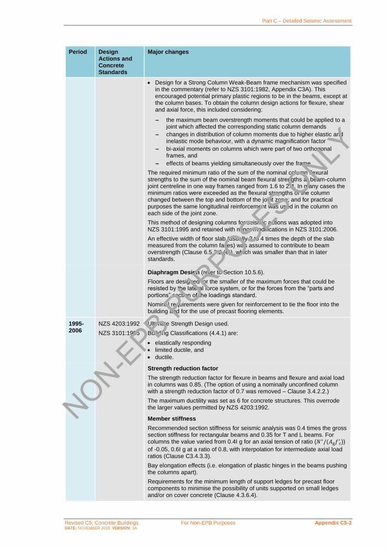
Part C – Detailed Seismic Assessment
Revised C5: Concrete Buildings For Non-EPB Purposes Appendix C5-3 DATE: NOVEMBER 2018 VERSION: 1A
Period Design Actions and Concrete Standards
Major changes
• Design for a Strong Column Weak-Beam frame mechanism was specified in the commentary (refer to NZS 3101:1982, Appendix C3A). This encouraged potential primary plastic regions to be in the beams, except at the column bases. To obtain the column design actions for flexure, shear and axial force, this included considering:
– the maximum beam overstrength moments that could be applied to a joint which affected the corresponding static column demands
– changes in distribution of column moments due to higher elastic and inelastic mode behaviour, with a dynamic magnification factor
– bi-axial moments on columns which were part of two orthogonal frames, and
– effects of beams yielding simultaneously over the frame.
The required minimum ratio of the sum of the nominal column flexural strengths to the sum of the nominal beam flexural strengths at beam-column joint centreline in one way frames ranged from 1.6 to 2.4. In many cases the minimum ratios were exceeded as the flexural strengths of the column changed between the top and bottom of the joint zone; and for practical purposes the same longitudinal reinforcement was used in the column on each side of the joint zone.
This method of designing columns for seismic actions was adopted into
NZS 3101:1995 and retained with minor modifications in NZS 3101:2006.
An effective width of floor slab (usually 2 to 4 times the depth of the slab measured from the column faces) was assumed to contribute to beam overstrength (Clause 6.5.3.2 (e)), which was smaller than that in later standards.
Diaphragm Design (refer to Section 10.5.6).
Floors are designed for the smaller of the maximum forces that could be resisted by the lateral force system, or for the forces from the “parts and
portions” section of the loadings standard.
Nominal requirements were given for reinforcement to tie the floor into the building and for the use of precast flooring elements.
1995-2006
NZS 4203:1992
NZS 3101:1995
Ultimate Strength Design used.
Building Classifications (4.4.1) are:
• elastically responding
• limited ductile, and
• ductile.
Strength reduction factor
The strength reduction factor for flexure in beams and flexure and axial load in columns was 0.85. (The option of using a nominally unconfined column with a strength reduction factor of 0.7 was removed – Clause 3.4.2.2.)
The maximum ductility was set as 6 for concrete structures. This overrode the larger values permitted by NZS 4203:1992.
Member stiffness
Recommended section stiffness for seismic analysis was 0.4 times the gross section stiffness for rectangular beams and 0.35 for T and L beams. For columns the value varied from 0.4I g for an axial tension of ratio (𝑁∗/(𝐴g𝑓 c
′ ))
of -0.05, 0.6I g at a ratio of 0.8, with interpolation for intermediate axial load ratios (Clause C3.4.3.3).
Bay elongation effects (i.e. elongation of plastic hinges in the beams pushing the columns apart).
Requirements for the minimum length of support ledges for precast floor components to minimise the possibility of units supported on small ledges and/or on cover concrete (Clause 4.3.6.4).
NON-EPB P
URPOSES ONLY
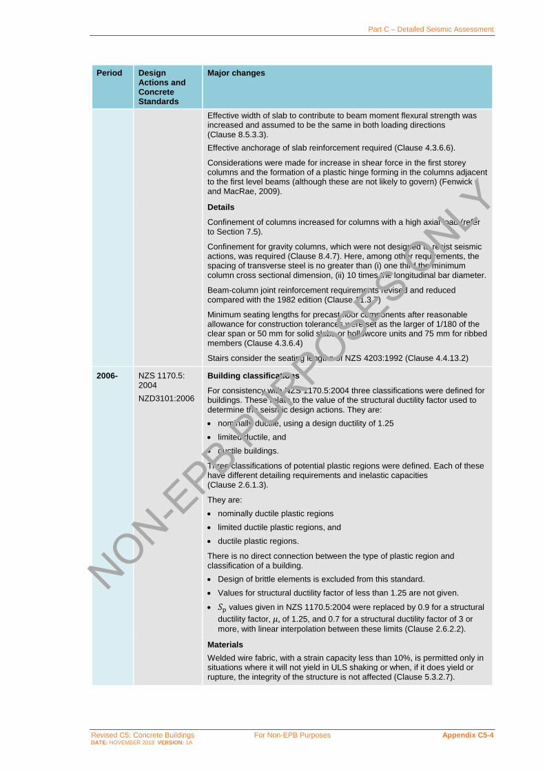
Part C – Detailed Seismic Assessment
Revised C5: Concrete Buildings For Non-EPB Purposes Appendix C5-4 DATE: NOVEMBER 2018 VERSION: 1A
Period Design Actions and Concrete Standards
Major changes
Effective width of slab to contribute to beam moment flexural strength was increased and assumed to be the same in both loading directions (Clause 8.5.3.3).
Effective anchorage of slab reinforcement required (Clause 4.3.6.6).
Considerations were made for increase in shear force in the first storey columns and the formation of a plastic hinge forming in the columns adjacent to the first level beams (although these are not likely to govern) (Fenwick and MacRae, 2009).
Details
Confinement of columns increased for columns with a high axial load (refer to Section 7.5).
Confinement for gravity columns, which were not designed to resist seismic actions, was required (Clause 8.4.7). Here, among other requirements, the spacing of transverse steel is no greater than (i) one third the minimum column cross sectional dimension, (ii) 10 times the longitudinal bar diameter.
Beam-column joint reinforcement requirements revised and reduced compared with the 1982 edition (Clause 11.3.7)
Minimum seating lengths for precast floor components after reasonable allowance for construction tolerances were set as the larger of 1/180 of the clear span or 50 mm for solid slabs or hollowcore units and 75 mm for ribbed members (Clause 4.3.6.4)
Stairs consider the seating lengths of NZS 4203:1992 (Clause 4.4.13.2)
2006- NZS 1170.5: 2004
NZD3101:2006
Building classifications
For consistency with NZS 1170.5:2004 three classifications were defined for buildings. These relate to the value of the structural ductility factor used to
determine the seismic design actions. They are:
• nominally ductile, using a design ductility of 1.25
• limited ductile, and
• ductile buildings.
Three classifications of potential plastic regions were defined. Each of these have different detailing requirements and inelastic capacities (Clause 2.6.1.3).
They are:
• nominally ductile plastic regions
• limited ductile plastic regions, and
• ductile plastic regions.
There is no direct connection between the type of plastic region and classification of a building.
• Design of brittle elements is excluded from this standard.
• Values for structural ductility factor of less than 1.25 are not given.
• 𝑆p values given in NZS 1170.5:2004 were replaced by 0.9 for a structural
ductility factor, 𝜇, of 1.25, and 0.7 for a structural ductility factor of 3 or
more, with linear interpolation between these limits (Clause 2.6.2.2).
Materials
Welded wire fabric, with a strain capacity less than 10%, is permitted only in situations where it will not yield in ULS shaking or when, if it does yield or rupture, the integrity of the structure is not affected (Clause 5.3.2.7).
NON-EPB P
URPOSES ONLY

Part C – Detailed Seismic Assessment
Revised C5: Concrete Buildings For Non-EPB Purposes Appendix C5-5 DATE: NOVEMBER 2018 VERSION: 1A
Period Design Actions and Concrete Standards
Major changes
Member stiffness
Minor revisions were made to the section stiffness where a high grade reinforcement was used (Clause C6.9.1).
Capacity design (Clause 2.6.5)
Contribution of prestressed floor components to overstrength of beams is
considered (Clause 9.4.1.6.2).
The difference in effective widths of floor slabs contributing to nominal negative moment flexural strength of beams and to overstrength of beams is
considered (Clauses 9.4.1.6.1 and 9.4.1.6.2).
Two methods are permitted for assessing capacity design actions in columns:
• The first method is based on the one contained in NZS 3101:1995 Appendix A with modifications to consider bi-axial actions more directly and to allow for the effects of elongation of beams on plastic hinge locations. In this method, each column above the primary plastic hinge located at its base of the column is proportioned and detailed with the aim of minimising inelastic deformation that may occur (Method A in Appendix D, Clause D3.2 in the NZS 3101:2006).
• The second method permits a limited number of potential plastic hinges in the columns provided the remaining columns have sufficient nominal strength to ensure that the storey column sway shear strength exceeds the storey beam sway shear strength in each storey by a nominated margin. The beam-sway storey shear strength is calculated assuming overstrength actions are sustained in all the potential plastic regions associated with the storey being considered (refer to Appendix D, Clause D3.3 in the NZS 3101:2006). This method has more restrictions on the lap positions of longitudinal bars and requiring more confinement reinforcement than the first method.
The significance of elongation of plastic hinges in beams on the actions in columns is recognised. In particular, elongation can cause plastic hinges, which are not identified in standard analyses, to form in columns immediately above or below the first elevated level. This can increase the shear forces induced in the columns. However, as the requirement for confinement reinforcement is generally more critical than shear reinforcement this is unlikely to be critical for the shear strength of these columns (refer to Clauses 10.4.7.1.2, B8.4, C2.6.1.3.3, C5.3.2, C10.4.6.6, C10.4.7.2.1 in the NZS 3101:2006).
In calculating overstrength actions in beams, allowance needs to be made for the possible material strengths and the increase in stress that may be sustained due to strain hardening. Strain levels are much higher in overstrength conditions than in normal ultimate strength design conditions. As strain levels increase the width of floor slab that acts with a beam increases. Consequently a greater width of slab needs to be assumed to contribute to overstrength than to design strength. This effect is recognised in the NZS 3101:2006 (Clauses 9.4.1.6.1 and 9.4.1.6.2) but it was not recognised in earlier standards.
Precast prestressed floor units in a floor slab, which span past potential plastic hinges in a beam, can make a very significant difference to the overstrength capacity of plastic hinges. A method of assessing the strength
due to this source is given in the Standard (Clause 9.4.1.6.2).
Strength design
Primary plastic hinges detailed in terms of likely ULS inelastic demands. These demands are written in terms section curvature for a specified plastic hinge length, which is similar to specifying a plastic rotation (refer to
Clause 2.6.1).
NON-EPB P
URPOSES ONLY

Part C – Detailed Seismic Assessment
Revised C5: Concrete Buildings For Non-EPB Purposes Appendix C5-6 DATE: NOVEMBER 2018 VERSION: 1A
Period Design Actions and Concrete Standards
Major changes
Serviceability limit state (SLS) with earthquake
New requirements for fully ductile (but not nominal or limited ductile structures) (Clause 2.6.3.1).
The structural ductility that can be used in the ULS is limited to 6 for buildings of normal importance; and in some cases a lower value is required (Clause 2.6.1.2d).
For the SLS a structural ductility factor of 1 is required for SLS1, but a value of 2 may be used for SLS2 (Clause 2.6.2.3.1). However, SLS2 is only applied to buildings of high importance (NZS 1170:2004, Clause 5, 2.1.4).
Clause 2.6.3.1 requires either that:
• the serviceability design strength is equal to, or exceeds, the serviceability
design actions, or
• analysis shows that crack widths and deflections remaining after a SLS earthquake are acceptable considering the effect of inelastic deformation caused by moment redistribution and other shake down effects associated with repeated inelastic displacements during an earthquake.
Strength requirements for the SLS are related to the average strength of structural sections. This is taken as the nominal strength with a strength reduction factor of 1.1 (Clause 2.6.3.2) to correspond to average material strengths.
Diaphragm Design
Similar material to NZS 3101:1995.
Strut and tie analysis required for forces induced in the diaphragms associated with the ultimate limit-state, or with actions associated with
overstrength in potential plastic regions (Clause 13.3.3)
Floors containing precast prestressed units have special requirements (NZS 3101: 2006 plus Amendment 2) relating to (Fenwick and MacRae,
2009):
• limiting the possibility of the floors falling off supports (Clause 18.7.4)
• limiting the possibility of brittle failure by:
– requiring for low friction bearing strips with hollowcore units (Clause 18.7.4)
– requiring a thin linking slab between a precast unit and a parallel structural element, such as a beam or wall, which may deflect in a vertical direction relative to the precast unit. This is required to prevent the load transfer between the structural elements causing the precast units to fail (Clause 18.6.7.2)
– specifying requirements for shear strength of precast units in zones where overstrength actions can cause tensile stresses to be induced on the top surface of the precast units. In this situation the shear strength is reduced to a value comparable with a non-prestressed beam of the same dimensions (Clause 19.3.11.2.4)
– specifying the position where reinforcement connecting the precast unit to the supporting structure is cut off or reduced is based on the capacity of the floor to sustain the negative moments and axial tension. These may be induced in the floor when overstrength actions act at the supports and vertical ground motion induces negative moments in the floor (Clause 19.4.3.6)
– cautioned against supporting precast units on structural elements that may deform and induce torsional moments as these may lead to torsional failure of the floor unit. This situation can be critical for hollowcore flooring (Clause C19.4.3.6).
NON-EPB P
URPOSES ONLY

Part C – Detailed Seismic Assessment
Revised C5: Concrete Buildings For Non-EPB Purposes Appendix C5-7 DATE: NOVEMBER 2018 VERSION: 1A
Historical Reinforcing Steel Properties in New Zealand
C5B.1 General
The first New Zealand standard to regulate the mechanical properties of steel bars for
reinforcing concrete is likely to have been NZS 197:1949 (based on BS 785:1938) “Rolled
steel bars and hard drawn steel wire”. This standard only referred to plain round bars.
Before NZS 197:1949 (BS 785:1938), there was apparently no specific national standard to
cover reinforcing steel. However, it can be reasonably assumed that steel reinforcement was
regulated by BS 165:1929, which was the previous version of BS 785:1938 used in
New Zealand from 1949.
Deformed bars were introduced in 1963 with NZSS 1693:1962 “Deformed steel bars of
structural grade for Reinforced Concrete”. A 227 MPa (33,000 psi) yield stress steel bar was
first introduced and then replaced in 1968 (Amendment 1 of NZSS 1693:1962) by a 275 MPa
(40,000 psi yield stress steel bar).
Note:
It can therefore be assumed that plain round bars were used in concrete buildings at least
until the mid-1960s. The required development length for plain round bars can be taken
as not less than twice that for deformed bars specified in NZS 3101:2006.
Also note that during cyclic loading the bond degradation for plain round bars is more
significant than for deformed bars (Liu and Park, 1998 and 2001; Pampanin et al., 2002).
Hence, old structures reinforced with plain round longitudinal bars will show a greater
reduction in stiffness during cyclic loading. As a reference value, as part of quasi-static
cyclic load tests of beam-column joint subassemblies reinforced by plain round
longitudinal bars at the University of Canterbury, the measured lateral displacements were
approximately twice those of similar assemblies reinforced by deformed longitudinal bars
at similar stages of loading (Liu and Park, 1998 and 2001).
Often plain round bars were terminated with hooks to provide reliable development of the
bars, but this was not always the case.
In 1964 another standard relating to deformed steel bars was issued: NZSS 1879:1964
“Hot rolled deformed bars of HY 60 (High yield 60,000 psi) for Reinforced Concrete”.
This standard introduced a higher yield steel bar with a yield stress of about 414 MPa
(60,000 psi). At this stage, there were three standards for steel reinforcing bars: one for
plain round bars (NZS 197:1949) and two for deformed bars (NZSS 1693:1962 and
NZSS 1879:1964).
Note:
Reinforcing steel from the pile caps of the Thorndon overbridge in Wellington constructed
in the 1960s had a measured mean yield strength of 318 MPa with a standard deviation of
19 MPa (Presland, 1999).
NON-EPB P
URPOSES ONLY
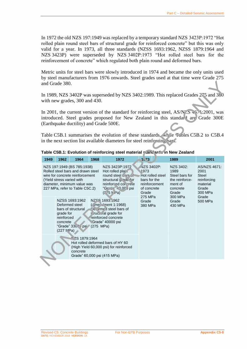
Part C – Detailed Seismic Assessment
Revised C5: Concrete Buildings For Non-EPB Purposes Appendix C5-8 DATE: NOVEMBER 2018 VERSION: 1A
In 1972 the old NZS 197:1949 was replaced by a temporary standard NZS 3423P:1972 “Hot
rolled plain round steel bars of structural grade for reinforced concrete” but this was only
valid for a year. In 1973, all three standards (NZSS 1693:1962, NZSS 1879:1964 and
NZS 3423P) were superseded by NZS 3402P:1973 “Hot rolled steel bars for the
reinforcement of concrete” which regulated both plain round and deformed bars.
Metric units for steel bars were slowly introduced in 1974 and became the only units used
by steel manufacturers from 1976 onwards. Steel grades used at that time were Grade 275
and Grade 380.
In 1989, NZS 3402P was superseded by NZS 3402:1989. This replaced Grades 275 and 380
with new grades, 300 and 430.
In 2001, the current version of the standard for reinforcing steel, AS/NZS 4671:2001, was
introduced. Steel grades proposed for New Zealand in this standard are Grade 300E
(Earthquake ductility) and Grade 500E.
Table C5B.1 summarises the evolution of these standards, while Tables C5B.2 to C5B.4
in the next section list available diameters for steel reinforcing bars.
Table C5B.1: Evolution of reinforcing steel material standards in New Zealand
1949 1962 1964 1968 1972 1973 1989 2001
NZS 197:1949 (BS 785:1938) Rolled steel bars and drawn steel wire for concrete reinforcement (Yield stress varied with diameter, minimum value was 227 MPa, refer to Table C5C.2)
NZS 3423P:1972 Hot rolled plain round steel bars of structural grade for reinforced concrete “Grade” 40,000 psi (275 MPa)
NZS 3402P: 1973 Hot rolled steel bars for the reinforcement of concrete Grade 275 MPa Grade 380 MPa
NZS 3402: 1989 Steel bars for the reinforce-ment of concrete Grade 300 MPa Grade 430 MPa
AS/NZS 4671:2001 Steel reinforcing material Grade 300 MPa Grade 500 MPa NZSS 1693:1962
Deformed steel bars of structural grade for reinforced concrete “Grade” 33000 psi (227 MPa)
NZSS 1693:1962 (Amendment 1:1968) Deformed steel bars of structural grade for reinforced concrete “Grade” 40000 psi (275 MPa)
NZS 1879:1964 Hot rolled deformed bars of HY 60 (High Yield 60,000 psi) for reinforced concrete Grade” 60,000 psi (415 MPa)
NON-EPB P
URPOSES ONLY

Part C – Detailed Seismic Assessment
Revised C5: Concrete Buildings For Non-EPB Purposes Appendix C5-9 DATE: NOVEMBER 2018 VERSION: 1A
C5B.2 Historically Specified Reinforcing Bar Sizes
Table C5B.2: Available diameters of steel reinforcement bars – before the mid-1970s
NZS 1693:1962 NZS 1879:1964 NZS 3423P:1972
Bar
designation
d
inch (mm)
Bar
designation
d
inch (mm)
Bar
designation
d
inch (mm)
3
4
5
6
7
8
9
10
11
121
3/8 (9.525)
1/2 (12.7)
5/8 (15.875)
3/4 (19.05)
7/8 (22.225)
1.000 (25.4)
1 1/8 (28.575)
1 1/4 (31.75)
1 3/8 (34.925)
1 1/2*(38.1)
3
4
5
6
7
8
9
10
11
121
3/8 (9.525)
1/2 (12.7)
5/8 (15.875)
3/4 (19.05)
7/8 (22.225)
1.000 (25.4)
1 1/8 (28.575)
1 1/4 (31.75)
1 3/8 (34.925)
1 1/2*(38.1)
3/8 (9.525)
1/2 (12.7)
5/8 (15.875)
3/4 (19.05)
7/8 (22.225)
1.000 (25.4)
1 1/8 (28.575)
1 1/4 (31.75)
1 3/8 (34.925)
1 1/2(38.1)
2 (50.80)
Note:
1. Introduced in 1970
Table C5B.3: Available diameters of steel reinforcement bars – from the mid-1970s onward
NZ 3402P:1973 (Stage 1)
NZ 3402P:1973 (Stage 2)
NZS 3402:1989 AS/NZS 4671:2001
Bar
designation
d
(inch)
d
(mm)
Bar
designation
d
(mm)
Bar
designation
d
(mm)
Bar
Designation
d
(mm)
R10
R13
R16
R20
R22
R25
R28
R32
R38
D10
D13
D16
D20
D22
D25
D28
D32
D38
-
½
-
-
7/8
-
-
-
1 ½
10
12.7
16
20
22.23
25.4
28
32
38.1
R10
R12
R16
R20
R24
R28
R32
R40
D10
D12
D16
D20
D24
D28
D32
D40
10
12
16
20
24
28
32
40
R6
R8
R10
R12
R16
R20
R24
R28
R32
R40
D6
D8
D10
D12
D16
D20
D24
D28
D32
D40
6
8
10
12
16
20
24
28
32
40
R6
R10
R12
R16
R20
R25
R32
R40
D6
D10
D12
D16
D20
D25
D32
D40
6
10
12
16
20
25
32
40
NON-EPB P
URPOSES ONLY

Part C – Detailed Seismic Assessment
Revised C5: Concrete Buildings For Non-EPB Purposes Appendix C5-10 DATE: NOVEMBER 2018 VERSION: 1A
C5B.3 Historically Specified Mechanical Properties of Steel Reinforcing Bars
The evolution of standards for the mechanical properties of steel reinforcement bars is
summarised in the following tables.
Table C5B.4: Mechanical properties of steel reinforcement bars – pre-1960s
NZSS 197:1949 (BS 785:1938)
Type of steel Plain round bar
Mild steel (MS) Medium tensile (MT)
High tensile (HT)
Yielding stress Bar size (diameter) MS MT HT
Up to 1 inch Not Specified 19.5 tsi (≈ 301 MPa)
23 tsi (≈ 355 MPa)
Over 1 to 1½ inch 18.5 tsi (≈ 286 MPa)
22 tsi (≈ 340 MPa)
Over 1½ to 2 inch 17.5 tsi (≈ 270 MPa)
21 tsi (≈ 324 MPa)
Over 2 to 2½ inch 16.5 tsi (≈ 255 MPa)
20 tsi (≈ 309 MPa)
Over 2½ to 3 inch 16.5 tsi (≈ 255 MPa)
19 tsi (≈ 294 MPa)
Tensile strength ≥ 28 tsi (≈ 433 MPa)
≥ 33 tsi (≈ 510 MPa)
≥ 37 tsi (≈ 572 MPa)
≤ 33 tsi (≈ 510 MPa)
≤ 38 tsi (≈ 587 MPa)
≤ 43 tsi (≈ 664 MPa)
Elongation at fracture (%)
Up to 1 inch ≥ 20(1) ≥ 18(1) ≥ 18(1)
Over 1 to 1½ inch ≥ 16(1) ≥ 14(1) ≥ 14(1)
Under ⅜ inch ≥ 24(2) ≥ 22(2) ≥ 22(2)
Note:
tsi = tons per square inch
Conversions undertaken based on long tons
1. Measured on a minimum 8 diameters gauge length.
2. Measured on a minimum 4 diameters gauge length.
Standard Steel Property
NON-EPB P
URPOSES ONLY

Part C – Detailed Seismic Assessment
Revised C5: Concrete Buildings For Non-EPB Purposes Appendix C5-11 DATE: NOVEMBER 2018 VERSION: 1A
Table C5B.5: Mechanical properties of steel reinforcement bars – 1960s to mid-1970s
NZSS 1693:1962
NZSS 1693 Amendment 1 1968
NZSS 1879:1964
Type of steel Grade 33 Grade 40 Grade HY60
Yielding stress 33,000 psi
(≈ 228 MPa)
40,000 psi
(≈ 276 MPa)
60,000 psi
(≈ 414 MPa)
Tensile strength ≥ 55,000 psi (≈ 379 MPa)
≥ 55,000 psi (≈ 379 MPa)
≥ 1.2 × yield stress and ≥ 90,000 psi
(≈ 621 MPa)
≤ 75,000 psi (≈ 517 MPa)
≤ 75,000 psi (≈ 517 MPa)
Elongation at fracture (%)
≥ 20(1) ≥ 20(1) ≥ 12(1)
Note:
psi = pounds per square inch
1. Measured on a minimum 5 diameters gauge length.
Table C5B.6: Mechanical properties of steel reinforcement bars – 1970s onwards
NZ 3402P:1973 NZS 3402:1989 AS/NZS 4671:2001
Type of steel Grade 275
Grade 380
Grade 300 Grade 430 Grade 300 Grade 500
Yielding stress (MPa)
• Lower bound
• Upper bound
275 380
≥ 275(min) (300(k))
≤ 380(max) (355(k))
≥ 410(min) (430(k))
≤ 520(max) (500(k))
≥ 300(k)
≤ 380(k)
≥ 500(k)
≤ 600(k)
Tensile Strength (MPa)
≥ 380
≤ 520
≥ 570* Not specified Not specified
Ratio 𝑅m/𝑅e (𝑇𝑆/𝑌𝑆) Not specified 1.15 ≤ 𝑇𝑆
𝑌𝑆 ≤ 1.50 1.15 ≤
𝑇𝑆
𝑌𝑆 ≤ 1.40 1.15 ≤
𝑅m
𝑅e
≤ 1.50
1.15 ≤ 𝑅m
𝑅e
≤ 1.40
Elongation at maximum force 𝐴gt
(%)
Not specified Not specified ≥ 15 ≥ 10
Elongation at fracture (%)
≥ 20(1) ≥ 12(1) ≥ 20(1) ≥ 12(1) Not specified
Note:
* But not less than 1.2 times the actual yield stress
1. Measured on a minimum 4 diameters gauge length.
𝑘 characteristic value
𝑇𝑆 = tensile strength
𝑌𝑆 = yield stress
𝑅m = value of maximum tensile strength (determined from a single tensile test in accordance with AS 1391)
𝑅e = value of the yield stress or 0.2% proof stress (determined from a single tensile test in accordance with
AS 1391)
Standard Steel Property
Standard Code Steel
Property
NON-EPB P
URPOSES ONLY

Part C – Detailed Seismic Assessment
Revised C5: Concrete Buildings For Non-EPB Purposes Appendix C5-12 DATE: NOVEMBER 2018 VERSION: 1A
C5B.4 Mechanical Properties of Mesh
The evolution of Standards for hard drawn steel wire and mesh for concrete reinforcement
is shown in Table C5B.7.
Table C5B.7: Evolution of hard drawn steel wire and mesh for concrete reinforcement
standards in New Zealand
1949 1972 1975 2001
NZS 197:1949 (BS 785:1938) Rolled steel bars and hard drawn steel wire for
concrete reinforcement
NZS 3421:1972 Hard drawn steel wire for concrete reinforcement (metric and imperial
units)
NZS 3421:1975 Hard drawn steel wire for concrete reinforcement (metric
units)
AS/NZS 4671:2001 Steel reinforcing material
NZS 3422:1972 Welded fabric of drawn steel wire for concrete reinforcement (metric units)
NZS 3422:1975 Welded fabric of drawn steel wire for concrete reinforcement (metric units)
Steel wire for concrete reinforcement was originally regulated in New Zealand by the first
local steel code NZS 197:1949 (BS 785:1938). The tensile strength limits were between
37 ton/in2 (510 MPa) and 42 ton/in2 (580 MPa). The elongation limit was 7.5% measured
over a gauge length of 8 times the diameter. This standard remained valid until 1972.
In 1972, NZS 3421:1972 and NZS 3422:1972 replaced the old standard. The first of these
provided specifications for hard drawn steel wire; the second, for welded fabric hard drawn
steel wire. Hard drawn steel wires were normally available in diameters not greater than
0.1 inches (12.7 mm) and not less than 0.08 inches (2.0 mm). The minimum 0.2 percent
proof stress limit was 70,000 lbf/in2 (483 MPa) while the minimum tensile strength was
83,000 lbf/in2 (572 MPa). The mechanical property limits of welded fabric of drawn steel
wires were similar to the ones specified for hard drawn steel wires. A maximum tensile
strength limit was introduced equal to 124,000 lbf/in2 (855 MPa) for diameters up to and
including 0.128 in (3.25 mm) and 112,000 lbf/in2 (772 MPa) for diameters over 0.128 in.
In 1975, NZS 3421:1972 and NZS 3422:1972 were superseded by the metric units versions
NZS 3421:1975 Hard drawn steel wire for concrete reinforcement (metric units) and
NZS 3422:1975 Welded fabric of drawn steel wire for concrete reinforcement (metric units).
The first was applied to plain and deformed wires while the second only to plain ones.
The available diameters ranged between 2.5 mm and 8 mm. The mechanical property limits
were similar to those prescribed in the 1972 standards: 485 MPa for minimum 0.2 percent
prof stress; 575 MPa for minimum tensile strength and 855 MPa maximum tensile strength
(for diameters up and including 3.15 mm) and 775 MPa (for diameters over 3.15 mm).
The current AS/NZS 4671:2001 (Steel reinforcing materials) replaced the old
NZS 3421:1975 and NZS 3422:1975. This standard provides specifications for steel
reinforcing bars and mesh. The steel grades are Grade 300E and Grade 500E. The commonly
available mesh diameters are 6 mm, 7 mm, 8 mm and 9 mm for structural mesh and 4 mm
and 5.3 mm for non-structural mesh. The most common mesh pitch size for is 200 by
200 mm for structural mesh and 150 by 150 mm for non-structural mesh.
NON-EPB P
URPOSES ONLY

Part C – Detailed Seismic Assessment
Revised C5: Concrete Buildings For Non-EPB Purposes Appendix C5-13 DATE: NOVEMBER 2018 VERSION: 1A
Test Methods for Investigating Material Properties
C5C.1 Concrete
The following table summarises test methods for investigating concrete material properties.
Table C5C.1: Overview of destructive, semi-destructive and non-destructive tests for
investigating concrete material properties (De Pra, Bianchi and Pampanin, 2015;
Malek et al., 2015)
Method Capability/Use Advantages Disadvantages
DESTRUCTIVE TESTS
Compressive test Strength of concrete Direct evaluation of concrete strength from compressive tests on cylindrical specimens
Disturbance of the sample, so excessive damage to obtain a representative core of concrete
Previous test with pacometer necessary to individuate the regions without bars
SEMI-DESTRUCTIVE TESTS
Pull-out In-place estimation of the compressive and
tensile strengths
In-place strength of concrete can be quickly
measured
Pull-out device must be inserted in a hole drilled in
the hardened concrete
Only a limited depth of material can be tested
Pull-off/tear-off Direct tension test In situ tensile strength of concrete
Determining bond strength between existing concrete and repair material
Sensitivity to rate of loading
Penetration probe (Windsor probe)
Estimation of compressive strength, uniformity and quality of concrete
Measuring the relative rate of strength development of concrete at early ages
The equipment is easy to use (not requiring surface preparation)
The results are not subject to surface conditions and moisture content
Minimum edge distance and member thickness are requested
Not precise prediction of strength for concrete older than 5 years and where surface is affected by carbonation or cracking
NON-DESTRUCTIVE TESTS
Visual tests The first step in investigating concrete material
Quick evaluation of damage
No detailed information
Rebound hammer Measuring surface hardness of concrete to estimate compressive strength
The assessment of the surface layer strength
Results can only suggest the hardness of surface layer
Dura
bili
ty
test
Concrete electrical resistivity
Measuring the ability of the concrete to conduct the corrosion current
Inexpensive, simple and many measurements can be made rapidly
Not reliable at high moisture content
NON-EPB P
URPOSES ONLY

Part C – Detailed Seismic Assessment
Revised C5: Concrete Buildings For Non-EPB Purposes Appendix C5-14 DATE: NOVEMBER 2018 VERSION: 1A
Method Capability/Use Advantages Disadvantages
Permeability To evaluate the transfer properties of concrete (porosity)
Useful method to evaluate the risk of leaching, corrosion and freezing
Thickness limitation
Age, temperature dependent
Sufficient lateral sealing
Fiberscope To check the condition of cavities, and honeycombing in reinforced concrete
Voids detection along grouted post-stressed tendons
Direct visual inspection of inaccessible parts of an element
Semi destructive as the probe holes usually must be drilled
Needs additional fibre to carry light from an external source
Str
ess-W
ave
pro
pa
ga
tion
me
tho
ds
Ultrasonic pulse velocity
Evaluation of concrete strength and quality
Identification of internal damage and location of
reinforcement
Excellent for determining the quality and uniformity of concrete; especially for rapid survey of large areas and thick members
The measure can be distorted by the presence of lesions in the concrete
The test requires smooth surfaces for a good adhesion of the probes
No information about the depth of suspected flaw
Ultrasonic echo method
Quality control and integrity of concrete
Access to only one face is needed
Internal discontinuities and their sizes can be estimated
Limited member thickness
Impact echo method
Defects within concrete element such as delamination, voids, honeycombing
Access to only one face is needed
The ability of instrument is limited to less than 2 m thickness
Spectral analysis of surface waves
Determining the stiffness profile of a pavement
Depth of deteriorated concrete
Capability of determining the elastic properties of layered systems such as pavement and
interlayered concrete
Complex signal processing
Nucle
ar
me
thod
s
Gamma radiography
Location of internal cracks, voids and variations in density of concrete
Simple to operate
Applicable to a variety of materials
X-ray equipment is bulky and expensive
Difficult to identify cracks perpendicular to radiation beam
Backscatter radiometry
Determining in-place density of fresh or
hardened concrete
Access only to surface of test object
Since this method’s measurements are affected by the top 40 to 100 mm, best for assessing surface zone of concrete element
The accuracy of this method is lower than direct
transmission
Measurements are influenced by near surface material and are sensitive to chemical composition
CT scanning Concrete imaging 3D crack/damage monitoring
Sophisticated software for analysis
Not in situ application
Access to CT scanner needed
NON-EPB P
URPOSES ONLY

Part C – Detailed Seismic Assessment
Revised C5: Concrete Buildings For Non-EPB Purposes Appendix C5-15 DATE: NOVEMBER 2018 VERSION: 1A
Method Capability/Use Advantages Disadvantages
Infrared thermography
Detecting delamination, heat loss and moisture movement through concrete elements; especially for flat surfaces
Permanent records can be made
Tests can be done without direct access to surface by means of infrared cameras
Expensive technique
Reference standards are needed
Very sensitive to thermal interference from other heat sources
The depth and thickness of subsurface anomaly cannot
be measured
Ground penetrating radar
Identification of location of reinforcement, depth of cover, location of voids and cracks
Determination of in situ density and moisture content
Can survey large areas rapidly
Results must be correlated to test results on samples obtained
Low level signals from targets as depth increases
Acoustic emission Real time monitoring of concrete degradation growth and structural performance
A few transducers are enough to locate defects over large areas
Can detect the initiation and growth of cracks in concrete under stress
Passive technique, could be used when the structure is under loading
Ultrasonic tomography (MIRA)
Uses high frequency (greater than 20,000 Hz) sound waves to characterise the properties of materials or detect their defects
Thickness measurement, reinforcement location, and distress evaluation
Significant efforts and user expertise are required for measurement and data interpretation of large scale
application
Petrography Forensic investigation of concrete
Determining the composition and identifying the source of
the materials
Determination of w/c
Determining the depth of fire damage
Microscopic examination of concrete samples
Laboratory facilities as well as highly experienced personnel are needed to
interpret the result
Sclerometric method
Determination of compressive strength
Determination of a sclerometric index connected to compressive strength
The instrument must be in the horizontal direction or the reliability of results is reduced
Empirical formulas, based on probabilistic methods, are used to obtain the concrete strength
The preparation of the test surface is laborious and expensive
SonReb method Determination of compressive strength
The concomitant use of sclerometric and ultrasonic methods can reduce mistakes due to the influence of humidity and aging of concrete
Risk of regression on a small statistically representative sample
NON-EPB P
URPOSES ONLY
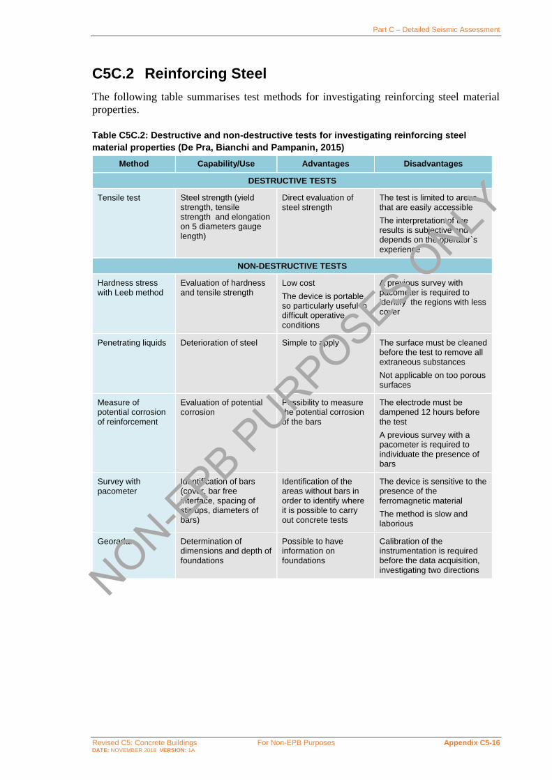
Part C – Detailed Seismic Assessment
Revised C5: Concrete Buildings For Non-EPB Purposes Appendix C5-16 DATE: NOVEMBER 2018 VERSION: 1A
C5C.2 Reinforcing Steel
The following table summarises test methods for investigating reinforcing steel material
properties.
Table C5C.2: Destructive and non-destructive tests for investigating reinforcing steel
material properties (De Pra, Bianchi and Pampanin, 2015)
Method Capability/Use Advantages Disadvantages
DESTRUCTIVE TESTS
Tensile test Steel strength (yield strength, tensile strength and elongation on 5 diameters gauge length)
Direct evaluation of steel strength
The test is limited to areas that are easily accessible
The interpretation of the results is subjective and depends on the operator`s
experience
NON-DESTRUCTIVE TESTS
Hardness stress with Leeb method
Evaluation of hardness and tensile strength
Low cost
The device is portable, so particularly useful in difficult operative
conditions
A previous survey with pacometer is required to identify the regions with less cover
Penetrating liquids Deterioration of steel Simple to apply The surface must be cleaned before the test to remove all extraneous substances
Not applicable on too porous surfaces
Measure of potential corrosion
of reinforcement
Evaluation of potential corrosion
Possibility to measure the potential corrosion
of the bars
The electrode must be dampened 12 hours before
the test
A previous survey with a pacometer is required to individuate the presence of bars
Survey with pacometer
Identification of bars (cover, bar free interface, spacing of stirrups, diameters of bars)
Identification of the areas without bars in order to identify where it is possible to carry out concrete tests
The device is sensitive to the presence of the
ferromagnetic material
The method is slow and laborious
Georadar Determination of dimensions and depth of foundations
Possible to have information on foundations
Calibration of the instrumentation is required before the data acquisition, investigating two directions
NON-EPB P
URPOSES ONLY

Part C – Detailed Seismic Assessment
Revised C5: Concrete Buildings For Non-EPB Purposes Appendix C5-17 DATE: NOVEMBER 2018 VERSION: 1A
Diaphragms Grillage Modelling/ Analysis Methodology
C5D.1 Assessment Approach
For buildings that are essentially rectangular with relatively uniform distribution of vertical
lateral force-resisting systems across the plan of the building, and no significant change of
plan with height, simple, hand-drawn strut and tie solutions can be used.
However, buildings with significant asymmetry in the location of lateral force-resisting
elements (distribution across the building plan, termination up the height of the building,
varying stiffness and/or strength between vertical elements) may require a more
sophisticated analysis. For these types of structures, a grillage method can be used to obtain
diaphragm design actions. Details of a simple grillage method appropriate for design office
use are given below (Holmes, 2015).
C5D.2 Grillage Section Properties
Grillage members are typically modelled as concrete elements, without reinforcement
modelled, in an elastic analysis program. Figure C5D.1 illustrates a grillage model
developed for a complicated podium diaphragm.
Figure C5D.1: Example of a grillage model for podium diaphragm (Holmes, 2015)
The recommended dimensions of the grillage elements for the modelling of a flat plate are
based on work completed by Hrennikoff (1941), as shown in Figure C5D.2. This solution is
based on a square grillage (with diagonal members). Rectangular grillages can also be used;
NON-EPB P
URPOSES ONLY

Part C – Detailed Seismic Assessment
Revised C5: Concrete Buildings For Non-EPB Purposes Appendix C5-18 DATE: NOVEMBER 2018 VERSION: 1A
the dimensions of the grillage beams will vary from those given for the square grillage
solution (Hrennikoff, 1941).
Figure C5D.2: Grillage beam dimensions for the square grillage (Hrennikoff, 1941)
Floors can be assumed to be uncracked for the purposes of diaphragm assessments. Given
that diaphragms typically contain low quantities of longitudinal reinforcing steel and
considering transformed section effects, it is not considered necessary to include longitudinal
reinforcement when determining grillage section properties. An exception to this is the
determination of the section properties for collector elements.
It is recommended that the effective stiffness of collector elements is based on the
transformed section of the concrete plus:
• the bars reinforcing the collector element, or
• the structural steel beam acting in a collector.
Typically, when a collector is stretched and the strain in the steel approaches the yield strain,
there will be significant cracking of the concrete that contributes to the collector. The
effective stiffness of the collector, in tension, will reduce. However, for the typical steel
contents of collector elements this reduction in stiffness is relatively small.
Note:
The collector is also typically required to resist compression forces due to the cyclic nature
of seismic loading. Therefore, for modelling the collector element it is generally
satisfactory to use either the transformed section of concrete and steel or the steel without
the concrete. The combined concrete and steel option is stiffer than the steel-only option,
so will attract more force.
C5D.3 Effective Width of Grillage Members
The recommended effective grillage member widths for orthogonal and diagonal members
are as follows (Hrennikoff, 1941):
• Orthogonal members:
- width A = 0.75 x grid spacing
- carries both tension and compression forces
• Diagonal members:
- width B = 0.53 x grid spacing
NON-EPB P
URPOSES ONLY

Part C – Detailed Seismic Assessment
Revised C5: Concrete Buildings For Non-EPB Purposes Appendix C5-19 DATE: NOVEMBER 2018 VERSION: 1A
- carries compression forces only.
C5D.4 Effective Thickness of Grillage Members
The recommended thickness of the grillage beams depends on the floor construction as
follows:
• Hollow-core and Tee units:
- parallel to the units: average thickness (per metre width) to match the combined areas
of the topping plus unit
- perpendicular to the units: the average thickness (per metre width) of the combined
areas of the topping and the top flange of the units.
• Rib and timber in-fill:
- parallel to the ribs: average thickness (per metre width) of combined areas of the
topping and ribs
- perpendicular to the ribs: average thickness (per metre width) of the topping only.
• In situ slabs and flat slabs:
- combined thickness of the topping and units (if present) parallel and transverse to the
units (if present).
• Steel profile composite floors:
- parallel to the webs: average of cross-section flange and web
- transverse to the webs: thickness of the flange.
• Spaced hollowcore units with in situ slabs:
- following the concepts above, the designer should rationalise the effective thickness,
parallel and perpendicular to the units.
C5D.5 Spacing of Grillage Members
It is recommended that a grillage beam spacing of 1.0 m is typically adequate to produce
reasonable distribution of forces (Gardiner, 2011). It is advisable to try larger and smaller
grid spacings to determine if the model is sufficiently refined.
In general terms, the point of sufficient refinement for the grid spacing is when the actions
reported in the beams of the grillage change very little from the previous trial.
In order to get a desirable, higher resolution of forces, grillage spacings should be reduced
while maintaining the square format (divide the main square grillage into sets of smaller
squares) for the following situations:
• Around the nodes where vertical structures (e.g. beams, columns, walls and eccentrically
braced frames (EBFs)) would be connected to the floor plate. This applies to vertical
elements, both on the perimeter of the floor as well as within the interior of the floor:
- internal frames
- frames, walls or EBFs, etc. next to floor penetrations (typically stairs, escalators and
lifts)
• Around floor penetrations (typically stairs, escalators and lifts)
• At re-entrant corners in the floor plate
NON-EPB P
URPOSES ONLY

Part C – Detailed Seismic Assessment
Revised C5: Concrete Buildings For Non-EPB Purposes Appendix C5-20 DATE: NOVEMBER 2018 VERSION: 1A
• For collectors, smaller sets of square grillages may be used either side of a collector (a
grillage member with properties relevant to the collector performance). If a collector is
relatively wide (say, greater than half the typical grillage spacing) consider modelling
the collector as a small grillage/truss along the length of a collector, with the smaller set
of squares either side of this.
C5D.6 Supports, Nodes and Restraint Conditions
The grillage is set up as a framework of struts. The junctions of the strut grillage framework
are called “nodes”. Floor inertia loads will typically be applied to all of the nodes of the
grillage. Each vertical structural element will be associated with one or more nodes in the
grillage as follows:
• Columns – typically a single node
• Walls – typically a number of nodes along the length of the wall.
The vertical translational degree of freedom of nodes which coincide with vertical structural
elements (i.e. columns or wall elements) should be fixed. The horizontal translational
degrees of freedom of these nodes should be left unrestrained. The reasons for this are as
follows:
• Forces going in to or out of the nodes associated with the vertical elements are in
equilibrium with the inertia and transfer or deformation compatibility forces within the
floor plate.
• If the horizontal degree of freedom was fixed, the loads applied to these nodes would go
directly to the support point and would not participate in the force distribution of the
floor plate.
• Transfer or deformation compatibility forces are internal forces and must balance at the
vertical supports and across the floor plate.
Note:
If all of the horizontal degrees of freedom are left unrestrained in a computer analysis
model, the analysis will not run. Therefore, it is recommended that two nodes are fixed;
with both horizontal degrees of freedom fixed at one node and with fixity only in the
direction of the applied inertia at the second node (i.e. free to move in the perpendicular
direction).
C5D.7 Loss of Load Paths due to Diaphragm Damage
Modify the grillage to account for anticipated diaphragm damage/deterioration.
For example, where floor to beam separation similar to that illustrated in Figure C5D.3 is
anticipated due to beam elongation, the diagonal strut in the grillage should be removed
recognising that the compression struts may not be able to traverse the damaged area (refer
also to Figure C5D.3).
NON-EPB P
URPOSES ONLY

Part C – Detailed Seismic Assessment
Revised C5: Concrete Buildings For Non-EPB Purposes Appendix C5-21 DATE: NOVEMBER 2018 VERSION: 1A
Figure C5D.3: Recommended grillage modelling at corner columns when frame elongation is anticipated (Holmes, 2015)
C5D.8 Application of Inertia Forces Introduced into the Grillage Model
Inertia of the floor, determined from pseudo-Equivalent Static Analysis (pESA) (refer to
Section C2), is distributed over the framework of grillage elements, at the nodes of the
orthogonal members of the grillage and in accordance to the tributary mass at each node:
• Tributary mass attributed to each node will include the seismic mass of the floor and any
of the vertical structures attached to that node or nodes of the floor (i.e. walls, columns,
beams, braces etc.).
• As a result of the “weighted” distribution of inertia associated with the appropriate mass
attributed to each node, the distribution of inertia will not be uniform across the floor.
There are concentrations of mass at frame lines, for example (beams, columns and
cladding), and a more even distribution of inertia over the floor areas.
• Note, that no inertia is placed where the diagonal member cross, because there is no node
where the diagonal members pass. The diagonal members run between the nodes of the
orthogonal grillage.
Inertia forces, applied to the structure, will be balanced by the forces at the supports/nodes
of the floor plate. Other “internal” forces that balance the remaining portion of the forces at
supports/nodes arise from deformation compatibility between the vertical structural systems
being constrained to similar lateral displaced shapes. The largest of these compatibility
forces are traditionally called “transfer” forces. Deformation compatibility forces occur in
all buildings on all floors to varying degrees. All forces, applied and internal, must be in
equilibrium.
NON-EPB P
URPOSES ONLY

Part C – Detailed Seismic Assessment
Revised C5: Concrete Buildings For Non-EPB Purposes Appendix C5-22 DATE: NOVEMBER 2018 VERSION: 1A
C5D.9 Application of “Floor Forces”
Forces entering or leaving the floor where the floor is connected to the vertical lateral force-
resisting structures have been called “floor forces”, 𝐹Di. Floor forces can be determined from
the results of the pESA (refer to Section C2) and, as illustrated in Figure C5D.4, are equal
to the difference in shears in vertical lateral load-resisting elements above and below the
diaphragm being assessed.
Figure C5D.4: Floor forces, 𝑭𝐃𝐢, determined from pESA (Holmes, 2015)
It is important that members of the vertical lateral force-resisting systems in the pESA
analysis model have in-plane and out-of-plane stiffness and that the analysis model has been
enabled to report both major and minor axis actions of vertical elements.
Outputs for such elements should report actions in the X and Y directions. Therefore, for a
given direction of earthquake attack, at each node there will be forces to be applied in the
X and Y directions (refer to Figure C5D.5). Care is required to ensure that sign conventions
(i.e. input and output of actions) are maintained.
Figure C5D.5: Floor forces 𝑭𝐃𝐢 in both X and Y directions at nodes connected to vertical elements – for one direction of earthquake attack (Holmes, 2015)
NON-EPB P
URPOSES ONLY

Part C – Detailed Seismic Assessment
Revised C5: Concrete Buildings For Non-EPB Purposes Appendix C5-23 DATE: NOVEMBER 2018 VERSION: 1A
C5D.10 Out-of-Plane Push and Pull of Vertical Elements
Vertical elements (i.e. walls, columns, braced frames) are pushed out-of-plane at some stage
during a seismic event. Depending on the magnitude of the inter-storey drift demands, these
elements may yield, exhibiting a permanent displacement out-of-plane. On reversal of the
direction of seismic displacement, the element will need to be pulled back the other way
(into the building). This action will subject the diaphragm to out-of-plane floor forces, 𝐹OP,i,
which can be significant.
Consideration is required of when and where the push or pull forces develop. One side of a
building has columns being pushed out of the building, while the other side is pulling the
columns back in to the building.
A recommended methodology for assessing the out-of-plane forces, 𝐹OP,i, is as follows:
• Determine the out-of-plane displacement profile for a column, etc., from the pESA.
• Using a linear elastic analysis program impose this displacement profile on the element.
• Determine the out-of-plane bending moment at the base of the element. If the
displacement is sufficient to yield the base of the element then scale the moments
determined by the linear elastic analysis to the overstrength of the element base.
• Determine the shear force distribution for this overstrength moment.
At each floor level, the difference in this shear force distribution is to be added to the pESA
model, which is then re-run and the out-of-plane forces, 𝐹OP,i, determined accordingly (i.e.
taking the difference in out-of-plane shear in the vertical elements above and below the
diaphragm being assessed).
C5D.11 Redistribution of Diaphragm Loads
It is probable that the reinforcing steel in the diaphragm may be insufficient to resist the
tensions determined from the pESA.
One method to account for floor regions that may have yielding and to allow for a
redistribution (plastic) of forces within the diaphragm is to adjust the section properties of
the yielding members. Accordingly, adjust the stiffness of the yielding members until the
yield forces are the outputs from the elastic pESA.
For each load case, it may take a couple of iterations to stabilise the redistribution of forces
within the diaphragm.
For those situations, when connections between the vertical lateral load-resisting elements
and the diaphragm are grossly overloaded (i.e. if very limited connectivity is provided), both
the global building model (i.e. the analysis model used to assess the capacity of the vertical
lateral load-resisting elements) and the pESA analysis model may need to be adjusted, so the
affected vertical lateral load-resisting elements are disconnected from the diaphragm.
NON-EPB P
URPOSES ONLY

Part C – Detailed Seismic Assessment
Revised C5: Concrete Buildings For Non-EPB Purposes Appendix C5-24 DATE: NOVEMBER 2018 VERSION: 1A
Assessing Precast Concrete Floor Systems
C5E.1 General
Precast concrete hollowcore, double-tee, rib and infill, and flat slab floor units are all seated
on ledges formed in their supporting beams as illustrated in Figure C5E.1(a). Unseating can
occur during earthquake shaking due to frame or wall elongation, supporting beam rotation,
and/or spalling of the support ledge and unit. Diaphragm action is achieved through the use
of an in-situ reinforced concrete topping, typically with starter bars connecting to the support
beams. This arrangement can provide rotational restraint at the ends of the units which can
lead to damage to the units, compromising gravity load support, unless modern support
detailing is provided (post-NZS 3101:2006 detailing with low friction bearing strip). For
buildings with older support detailing, the limiting drift at failure of the precast floors is
likely to be less than the limiting drift for the frame and may govern the earthquake rating
for the building as a whole.
Figure C5E.1: Section through precast concrete floor units illustrating (a) its construction and (b) elongation of beams alongside the floor units
This appendix focuses on identifying the drift demands in the primary structure that are likely
to cause all or part of a precast unit to lose gravity load support. It is noted, that unreliable
load paths (e.g. jamming of units, tension across topping to unit interface, etc.) may result in
gravity load support for units beyond the drifts indicated by this appendix; however, such
load paths cannot be reliably calculated or depended on to always be present and hence are
ignored in the recommended assessment process. Methods are provided for assessing the
limiting drift capacity for the following failure modes, depending on the type of precast floor
units:
Inter-storey Drift Capacity of Hollowcore Floor Systems (C5E.5):
• Loss of support to Hollowcore Floor Systems (C5E.5.2)
• Failure in negative moment zones near support (C5E.5.3)
Elongation
NON-EPB P
URPOSES ONLY

Part C – Detailed Seismic Assessment
Revised C5: Concrete Buildings For Non-EPB Purposes Appendix C5-25 DATE: NOVEMBER 2018 VERSION: 1A
• Positive moment failure and web cracking (C5E.5.4).
Inter-storey Drift Capacity of Double-Tee Floor Systems (C5E.6):
• Loss of support to Double-Tee Floor Systems (C5E.6.2)
• Failure of flange-hung double-tee floor units (C5E.6.3).
Inter-storey Drift Capacity of Rib and Infill Floors (C5E.7):
• Loss of support to Rib and Timber Infill Floor Systems (C5E.7.2)
• Positive moment rib failure near support (C5E.7.3)
• Negative moment failure near support (C5E.7.4).
Inter-storey Drift Capacity of Flat Slab Floors (C5E.8):
• Loss of support to Flat Slab Systems (C5E.8.2)
• Negative moment failure near support (C5E.8.3)
• Positive moment rib failure near support (C5E.8.4).
Rib and infill systems benefit from more integral construction and thicker slab uniformly
across the floor. It is noted that rib and infill systems can potentially develop secondary load
paths for gravity loads even if ribs experience failures. The secondary load paths arise from
the increased thickness of the cast-in-place portion of the floor system and the improved
bond with the ribs through closed stirrups (refer to Section C5E.7).
A significant life safety hazard (refer to Part A) will result should a precast floor unit or a
significant part of a unit become detached and fall. Such failures can be sudden and brittle.
When assessing brittle failure modes of precast concrete floor components (i.e. web-splitting
of hollowcore floor units, loss of support, etc.) the displacement demands determined from
the analysis of the primary lateral load resisting system should be increased by a factor of 2.
Note:
The factor of 2 reflects the uncertainties associated with estimating the probable drift
capacity of these mechanisms and the potential step change nature of the behaviour once
the building drift increases beyond these levels.
In terms of applying the provisions of these Guidelines to assess a score for these elements
the resulting factored displacement demands should be assumed to be the ULS seismic
demand.
Alternatively, the drift capacities given by this Section can be factored down by 2, before
comparing with the unfactored ULS seismic demands determined in accordance with
Section C3 (refer also guidance provided in Section C1).
Precast floors assessed using the criteria in this appendix are not intended to be considered
a severe structural weakness (SSW).
Precast floors, connected by a topping, also serve as diaphragms to distribute inertial forces
to the primary lateral systems. Diaphragms should be assessed in accordance with Section
C5.6.3.
NON-EPB P
URPOSES ONLY

Part C – Detailed Seismic Assessment
Revised C5: Concrete Buildings For Non-EPB Purposes Appendix C5-26 DATE: NOVEMBER 2018 VERSION: 1A
Assessments should be undertaken according to NZS 3101:2006 except as noted in this
appendix. Since NZS 3101:2006 is intended for new design, it may be more conservative
than is appropriate to achieve the intent of these guidelines as defined in Part A.
Note:
The material in this section particularly that on hollowcore floors, has largely been sourced
from the University of Canterbury Research Report 2010-02 by Fenwick et al. (2010),
further updated in 2018 based on experience from Canterbury and Kaikoura Earthquakes.
Fenwick et al. (2010) provides further details about the different failure modes and
examples which may be useful for an engineer implementing the provisions of this
appendix. Note that the provisions of this appendix should be considered to supersede any
recommendations found in Fenwick et al. (2010).
Additional detail on the behaviour of double-tee floors can be found in Hare et al. (2009).
C5E.2 Inspecting Precast Concrete Floor Systems
During site inspections, engineers are expected to identify the systems, sub-systems,
elements, members and connections, as described in Section C1. They should then use an
appropriate level of inspection to determine the condition of the precast floor system. This
may require removal of floor coverings and intrusive work in ceilings and wall cavities to
investigate and record the relevant details and damage from past earthquakes or other causes.
Buildings have a large numbers of precast concrete floor panels. The inspection and
investigation programme therefore needs to identify the locations where the panels are likely
to be subjected to demands (forces and deformations) from past earthquakes that could have
resulted in damage or exceeded their capacity. These locations will normally be at floor
levels developing largest inter-storey drifts as calculated using Section C2, and include floor
plan corners where deformation incompatibility and beam elongation can lead to higher
demands on precast floor units.
A statistically valid sample of the panels needs to be inspected, including locations where
their capacity is considered unlikely to be exceeded. This sample size will vary according to
building size and complexity of the flooring geometry and building type.
It is recommended that the sample should include;
• Critical floors identified in the assessment. These are typically the floors having the
highest inter-storey drift ratio (IDR) in the building, (but may also be transfer
diaphragms, high stress hot spots, or floors susceptible to greater elongation). Every unit
should be inspected on these floors for the issues outlined below.
• For all other floors a progressive enquiry approach should be undertaken starting at the
identified hotspots and corners of the floor and inspecting a suitable number of units in
every bay until a complete picture of the floor is gained. These targeted inspections
should entail as a minimum number 35% of all the precast units, evenly distributed across
any floor plate.
Engineers should relate any identified damage to the critical damage states described in the
SESOC/NZSEE (Wellington) Targeted Damage Evaluation Guidelines (2017) and the
research publication Henry et al (2017).
NON-EPB P
URPOSES ONLY

Part C – Detailed Seismic Assessment
Revised C5: Concrete Buildings For Non-EPB Purposes Appendix C5-27 DATE: NOVEMBER 2018 VERSION: 1A
Identification of the seating and end embedment details, and the locations and sizes of cracks
developed by shrinkage, creep, curtailed reinforcing, and service actions are important for
all three types of precast floor systems because they can significantly affect their seismic
performance. The inspection will normally verify and augment the construction drawing
details. The following aspects requiring careful inspection are common to all three flooring
systems:
• whether units span past columns or between columns
• the presence and geometry of starter bars or continuity reinforcement that could resist
relative movement of the supporting beam and precast unit
• cracking of the concrete topping at the ends of the precast units or curtailed reinforcing
• debonding between the precast unit and topping
• the condition of the ends of the precast units, including:
- transverse or corner cracking on the soffit
- loss of prestressing (i.e. retraction of the tendon ends)
• the geometry, reinforcing, armouring, and condition (especially spalling) of the
supporting ledges
• construction gaps that will reduce seating widths
• dimensions of any low-friction seating strips or mortar pads
• flooring system-specific features listed in the subsections below.
When inspecting a crack, the engineer should consider and record the following:
• the maximum crack width and where this occurs (noting that crack width should not
include spalling at the surface)
• the crack trajectory and visible extents at the surface
• how deep the crack propagates into the concrete
• whether or not non-destructive testing or coring is required
Note:
The inspection procedures described here are intended for the inspection of a building
before seismic assessment and retrofit. Due to prior earthquakes affecting buildings with
precast floors in New Zealand, the engineer should pay careful attention to the possibility
of previously unidentified damage from prior events, even for buildings for which a post-
earthquake damage assessment has been conducted.
Photographs provide useful records of crack trajectories, extents and widths. Close-up
photographs are best with a width gauge crossing the crack at the location of its maximum
width. The gauge provides a good location indicator to complement a written label with
the grid reference and floor level in an overview photograph. The cracks may need marks
alongside and at the ends to be visible in overview photographs.
A detailed inspection programme may be used for the purpose of substituting the
construction tolerance allowance from the assessment procedure, (20mm for hollowcore
and double tees), to reflect the as-built or actual site tolerances.
This seating tolerance allowance (20mm for hollowcore and double tees) has been adopted
in this assessment process based on a statistical analysis of the allowable construction
tolerances for New Zealand construction.
NON-EPB P
URPOSES ONLY

Part C – Detailed Seismic Assessment
Revised C5: Concrete Buildings For Non-EPB Purposes Appendix C5-28 DATE: NOVEMBER 2018 VERSION: 1A
Due to the critical nature of the outcomes for reduction in the seating length, a rigorous
approach should be undertaken to site measurement if the specified construction tolerance
from the assessment process is to be reduced.
This shall entail the following as a minimum;
For critical floors defined above, the seating length shall be measured for all precast floor
units on the floor.
For all other floors, ideally every unit should be measured for seating length, however, if
good agreement is found using the progressive enquiry approach (i.e. if 100% of the
measurements taken have a seating length within +/-5mm of the mean value) then the total
number of floor units measured may be reduced to every second precast floor unit. For
floors with very low drift demands (e.g. less than 0.5%), random inspections of units
would be sufficient.
Inspecting hollowcore floor systems
Issues that have been observed with hollowcore floor systems and that need careful attention
during inspections include:
• flooring units alongside a frame or wall that have no link slab to accommodate
differential vertical movements
• end details that will significantly influence the modes of failure, including the presence
of filled cells and reinforcement used in the cells. Cells may be filled due to concrete
running into the cells during casting of the top of the beams, or may be reinforced with
“paperclip” reinforcement if the units were provided shorter than the seating. Such
infilling will not be shown on plans and must be determined by inspection. Inspection
for paperclip must be done when the seating is identified to be less than 20mm.
Inspection for paperclip must be done when the seating is identified to be less than
20mm.
• internal web cracking or splitting (inspected using a borescope)
• where assessment based on this appendix identifies that a negative moment failure may
be the controlling failure mode, scanning of the length and spacing of starter bars should
be conducted.
• variances in seating lengths and short seating lengths (much less than original design
requirements) due to poor construction tolerances and placement of units.
Note:
The paperclip reinforcement detail will have a significant effect on the modes of failure
in the floor and should be checked even if not detailed in the original design or precast
shop drawings. Non-destructive investigation can be done with a cover meter to identify
the presence of reinforcing in the cells and then confirmed by more invasive testing or
drilling.
Inspections following earthquakes have shown that internal web cracking can exist in
regions where no outward signs of damage to a hollowcore floor are evident and invasive
review with a borescope may be the only way to determine the presence of this.
Non-destructive review and inspection of the seating length for hollowcore floors can be
difficult particularly in older forms of construction where the units were placed without
bearing strips. A simple means to undertake invasive inspection for seating length is to
NON-EPB P
URPOSES ONLY

Part C – Detailed Seismic Assessment
Revised C5: Concrete Buildings For Non-EPB Purposes Appendix C5-29 DATE: NOVEMBER 2018 VERSION: 1A
locally drill or break out a small slot (approx. 40mm width) in the cover concrete of the
supporting beam to find the back edge of the hollowcore unit. This inspection may be
carried out at the joints between two units such that the seating length can be established
for both units. If the unit is not necessarily square with the support beam, then inspection
is required at two locations over the width of the unit.
Inspecting double-tee floor systems
Issues that have been observed with double-tee floor systems that need careful attention
during inspections include:
• construction details that could lead to shortening of a flange-hung double-tee unit due to
imposed rotation and elongation
• seating details for web-supported and flange-hung units, particularly for cases supported
on corbels
• variances in seating length and short seating (much less than original design
requirements) due to poor construction tolerances and placement of units.
Inspecting rib and infill floor systems
Issues that have been observed with ribbed floor systems and that need careful attention
during inspection include:
• cracks within the ribs
• support condition for the ribs and presence of insitu concrete which may trap the unit,
preventing relative movement between rib and supporting beam
• the type, size, and distribution of stirrups connecting the topping and ribs
• topping slab reinforcing beneath the stirrups that could provide a secondary load path
and reliably prevent significant parts of the flooring system from falling.
Inspecting precast flat slab floor systems
Issues that have been observed with precast flat slab floor systems and that need careful
attention during inspection include:
• flooring units alongside a frame or wall that have no link slab to accommodate
differential vertical movements
• cracks in units, particularly at corner columns.
• variances in seating lengths and short seating (much less than original design
requirements) due to poor construction tolerances and placement of units.
C5E.3 Deformations Imposed on Precast Floor Systems
Precast floor systems must be able to accommodate deformations imposed by the supporting
structural system. Deformations arising from beam elongation and rotation expected in
moment resisting frames are described in Section C5E.3.1. Deformations imposed on precast
floor systems in wall buildings are described in Section C5E.3.2.
NON-EPB P
URPOSES ONLY

Part C – Detailed Seismic Assessment
Revised C5: Concrete Buildings For Non-EPB Purposes Appendix C5-30 DATE: NOVEMBER 2018 VERSION: 1A
Deformations arising from beam elongation and rotation
Elongation of plastic hinges can push beams supporting precast floor units apart and reduce
the contact length between the precast units and support ledge. However, as elongation is
related to the mid-depth of the beam containing the plastic hinge it is also necessary to allow
for further movement between precast units and support ledge due to rotation of the
supporting beam as illustrated in Figure C5E.2.
Movement of support relative to precast unit equals elongation of beam plus
column rotation, 𝜃, times height between beam centre-line and support seat, ℎs
Figure C5E.2: Displacement at support of precast unit due to elongation and rotation of support beam (Fenwick et al., 2010)
Displacement of structural members due to frame elongation can be calculated using the
following procedure, which is based on experimental measurements. Experimental testing
on structures with precast floor units (Fenwick, et al., 1981; Matthews, 2004; MacPherson,
2005; Lindsay, 2004) has demonstrated that frame elongation is partially restrained by
precast concrete floor units when they span parallel to the beams. Experience from
Canterbury and Kaikoura Earthquakes confirms that the greatest elongation occurs at the
beams framing into the corner columns, and considerably less elongation for beams framing
into internal beam-column joints.
Figure C5E.3 illustrates three plastic hinge elongation types, U, R1 and R2. U hinges are to
be considered unrestrained in assessment below. In general, R1 and R2 hinges may be
considered as restrained in the assessment below, except for R2 hinges are restrained by light
continuity bars (i.e. D12@600 or lighter, including case with no continuity reinforcement
over gravity beam).
NON-EPB P
URPOSES ONLY

Part C – Detailed Seismic Assessment
Revised C5: Concrete Buildings For Non-EPB Purposes Appendix C5-31 DATE: NOVEMBER 2018 VERSION: 1A
Figure C5E.3: Part plan of floor showing plastic hinge elongation types U, R1 and R2 (Fenwick et al., 2010)
For unrestrained plastic hinges little restraint is provided by the floor slab or the rest of the
frame and the elongation at mid-depth of the beam, δel, can be calculated as follows:
δel = 2.6𝜃p
2(𝑑 − 𝑑′) ≤ 0.036ℎb (for reversing plastic hinges) …C5E.1
δel =𝜃p
2(𝑑 − 𝑑′) ≤ 0.036ℎb (for unidirectional plastic hinges) …C5E.2
where:
ℎb = beam depth
𝜃p = plastic rotation in a beam plastic hinge.
For restrained plastic hinges where the units and the frame provides partial restraint to beam
elongation, the elongation at mid-depth of the beam, δel, can be taken as half the value
determined for unrestrained plastic hinges.
Note:
Based on observations in the Kaikoura Earthquake where beam plastic hinges at internal
beam-column joints demonstrated less cracking than beam plastic hinges at corner
columns, R2 hinges are considered herein as restrained except as noted for R2 hinges
restrained by light continuity reinforcement. This supersedes the recommendation of
Fenwick et al. (2010).
Equations C5E.1 and C5E.2 are applicable to reinforced concrete beams that are
sustaining inelastic deformations. Plastic rotations are used here to estimate beam
elongation given good agreement with experimental data (Marder et al., 2018). Note, that
NON-EPB P
URPOSES ONLY

Part C – Detailed Seismic Assessment
Revised C5: Concrete Buildings For Non-EPB Purposes Appendix C5-32 DATE: NOVEMBER 2018 VERSION: 1A
NZS 3101:2006 (A3) uses the same equations but with total rotation, instead of plastic
rotation, which provides a more conservative assessment of beam elongation.
Some recoverable frame elongation can still be expected prior to yield. Pending further
study, a minimum elongation in the order of 0.5% of beam depth is considered appropriate
even if the frame is not expected to yield.
Location of plastic hinge elongation
Where a precast unit spans multiple beams, and hence multiple plastic hinges, the amount of
elongation is determined for each plastic hinge as per Equations C5E.1 and C5E.2, as
appropriate. The amount of plastic hinge elongation which needs to be considered at the
support ends of the precast unit, is determined on the basis that all elongation from a beam
plastic hinge is attributed to the closest end of the precast unit being assessed - refer to
example in Figure C5E.4.
Equations C5E.1 and C5E.2 provide the expected elongation of the beams parallel to
the floor units. Units immediately adjacent to the elongating beam will need to accommodate
all of this expected elongation. Observation from past earthquakes indicates that the
elongation demands diminish the further the unit is away from the elongating beam
(e.g. frame lines 1 and 3 in Figure C5E.5). Figure C5E.5 defines an “elongation zone”, 𝑙e,
where the effects of elongation must be considered. The elongation zone shall be considered
to be half of the beam span when adjacent to an unrestrained plastic hinge, and one-quarter
of the beam span when adjacent to a restrained plastic hinge. For an interior beam (grid line 3
in Figure C5E.5), the elongation zone shall be taken as one-quarter of the span on either side
of the elongating beam. Any precast floor units terminating within the elongation zone, 𝑙e,
must consider elongation on both ends (attributed according to Figure C5E.4) when
assessing the limiting drifts for precast floor units according to this appendix.
Figure C5E.4: Plastic hinge elongation attributed to support locations of precast units
NON-EPB P
URPOSES ONLY

Part C – Detailed Seismic Assessment
Revised C5: Concrete Buildings For Non-EPB Purposes Appendix C5-33 DATE: NOVEMBER 2018 VERSION: 1A
Figure C5E.5: Definition of elongation zones
Note:
The “elongation zone” is specified here for assessment of an unretrofitted building. It is
strongly recommended that retrofits for seating be provided over the full length of the
supporting beam if required at any point along the beam.
In arriving at the recommendations for the elongation zone shown in Figure C5E.5, it is
assumed that the elongation will be less along frame line 3 as the gravity beam is
shallower. Lower elongation demands will lead to a shorter length, 𝑙e, over which
elongation needs to be considered in the assessment of the precast floor units.
In the following conditions, the elongation demands may be larger than typical conditions
and recommendation of 𝑙e = 𝐿/4 should be replaced by 𝑙e = 𝐿/2:
• internal beam framing in perpendicular to the perimeter frame (e.g. frame line 3) has
similar depth and therefore similar dilation characteristics to the perimeter frame
• elongation is large, caused by multiple bays of seismic frame
• where there is only mesh reinforcement over the internal gravity beam.
Rotation of support beam
Movement between precast units and support ledge due to rotation of the supporting beam
depend on whether the unit is located inside or outside the elongation zone defined above
(refer to Figure C5E.6).
NON-EPB P
URPOSES ONLY

Part C – Detailed Seismic Assessment
Revised C5: Concrete Buildings For Non-EPB Purposes Appendix C5-34 DATE: NOVEMBER 2018 VERSION: 1A
(a) Within the elongation zone (b) Outside the elongation zone
Figure C5E.6: Rotation of the supporting beam
Within the elongation zone, the movement between the precast unit and the support ledge
due to rotation of the support beam is given by:
𝛿r1 = (ℎb
2− ℎL) 𝜃 …C5E.3a
Outside the elongation zone, the movement between the precast unit and the support ledge
due to rotation of the support beam is given by:
𝛿r2 = ℎL𝜃 …C5E.3b
where:
ℎb = beam depth
ℎL = ledge height (i.e. vertical distance between top of slab and height at
which precast floor unit is supported)
𝜃 = beam rotation.
Beam rotation, 𝜃, can typically be estimated as the column drift ratio for cases where the
majority of the frame drift is accommodated by elastic and plastic deformation of the beams.
Note:
While 𝛿r1 will typically govern in the elongation zone, it is recommended to also check
𝛿r2 for cases where elongation may be limited.
Unit movement due to plastic strain in starter bars
The precast floor unit can be pushed away from the supporting beam by plastic strain in the
starter bars during prior cycles. This is a mechanism similar to that of beam elongation, with
the strain in the starter bars developing due to prying when the base of the unit is in contact
with the back of the support ledge. Most units can be considered partially restrained from
movement due to the restraint from the supporting beam. Hence, the unit movement due to
plastic strain in starter bars can be estimated as:
δel_unit = 1.3𝜃p
2(ℎL − 𝑑′) ≤ 0.018ℎL …C5E.4
NON-EPB P
URPOSES ONLY

Part C – Detailed Seismic Assessment
Revised C5: Concrete Buildings For Non-EPB Purposes Appendix C5-35 DATE: NOVEMBER 2018 VERSION: 1A
where:
𝜃p = (𝛿 − 𝛿e) ∗𝐿
(𝐿−2𝑠)
𝛿 = total drift
𝛿e = elastic drift
𝐿 = unit length
𝑠 = distance from column CL to ledge face
ℎL = depth from seating to top of beam
𝑑′ = cover to CL of starter bars.
Note:
Equation C5E.4 assumes the unit is partially restrained against elongation due to plastic
strain in the starter bars. Some units may be positioned such that plastic strain in starter
bars can develop without restraint. In such cases, it is advised to use twice the value from
Equation C5E.4 in determining 𝛿el_unit.
Total displacement
Total movement of precast floor unit units relative to the ledge providing support due to
elongation and rotation of support beams, ∆tot, is calculated as:
𝛿tot = max (∑ δ𝑒𝑙 + 𝛿r1; 𝛿r2 + 𝛿el_unit)
for units supported within the elongation zone, 𝑙e …C5E.5a
𝛿tot = 𝛿r2 + 𝛿el_unit for units supported outside the elongation zone, 𝑙e …C5E.5b
where sum in Equation C5E.5a is over all contributing elongating plastic hinges (as
illustrated in Figure C5E.4), and 𝛿el, 𝛿r1, 𝛿r2, 𝛿el_unit are calculated as defined above.
Deformations imposed on precast floor systems in wall buildings
Walls experience elongation during strong ground shaking which can impose significant
flexural demands on attached precast units (Figure C5E.7). Elongation at the wall centroid
should be estimated using Equation 7-15(c) of NZS 3101:2006-A3. Resulting elongation at
the wall ends can be determined by combining elongation at the centroid with the rotation
of the wall due to inter-storey drift.
Support beams connected in the plane of the wall will experience bending demands due to
both inter-storey drift and wall elongation as shown in Figure C5E.7. Beams framing
perpendicular to the wall will experience rotation equal to the inter-storey drift. Precast units
supported on these beams should be assessed in a manner similar to units supported outside
the elongation zone according to Equation C5E.5b.
NON-EPB P
URPOSES ONLY

Part C – Detailed Seismic Assessment
Revised C5: Concrete Buildings For Non-EPB Purposes Appendix C5-36 DATE: NOVEMBER 2018 VERSION: 1A
Figure C5E.7: Wall elongation and imposed demands on floor system
C5E.4 Inter-storey Drift Capacity of Precast Floor Components
General
The assessment of inter-storey drift capacity of diaphragms containing precast concrete floor
components needs to consider the following:
• loss of support of precast floor units, and
• failure of precast floor units due to seismic actions.
Failure of a precast floor unit is herein defined as damage to unit which is likely to result in
part or all of unit falling, thus constituting a significant life-safety hazard.
The following sections contain guidance for assessing the inter-storey drift capacity of:
• Hollowcore floor systems (C5E.5)
• Double tee floor systems (C5E.6)
• Rib-and-timber floor systems (C5E.7)
NON-EPB P
URPOSES ONLY

Part C – Detailed Seismic Assessment
Revised C5: Concrete Buildings For Non-EPB Purposes Appendix C5-37 DATE: NOVEMBER 2018 VERSION: 1A
• Flat slab floor systems (C5E.8).
C5E.5 Inter-storey Drift Capacity of Hollowcore Floor Systems
General
As shown in Figure C5E.8, the inter-storey drift capacity of hollowcore floor systems is
governed by loss of support (LoS), failure of the unit within the negative moment region
(Negative Moment Failure - NMF), or failure due to positive moment cracks near the support
(Positive Moment Failure – PMF). The last of these failure modes can be suppressed if the
seating for the hollowcore unit uses low friction bearing strips as required by Amendment 3
to NZS 3101:1995 (published in April 2004). If such support details are not included, the
end of the unit is likely to be trapped in the supporting beam and relative rotation of the
supporting beam will result in a positive moment crack near the support. Beam elongation
and support beam rotation (Section C5E.3) must be accommodated at the positive moment
crack. Collapse of all, or part, of the unit can result, if the positive moment crack exceeds
specified critical crack limit, or if the positive moment crack is also accompanied by web
splitting.
If anchorage detailing, as given in Clause 18.6.7 of NZS 3101:2006 A3 is provided,
including R16 bars in two (but no more) filled cells, it is not necessary to check positive
moment failure. Two well-anchored R16 bars matching the detailing requirements of
NZS 3101:2006 can also provide gravity load support if the seating length is exceeded, but
gravity load support must be checked for the seismic weight assuming a 30 degree slope of
R16 bars at the unseated end of the unit. The unit must still be checked for negative moment
failure even if detailing in accordance with NZS 3101:2006 is present.
Vertical seismic demands should be checked independently of lateral demands, consistent
with the approach prescribed in NZS 1170.5:2004 and NZS 3101:2006.
NON-EPB P
URPOSES ONLY

Part C – Detailed Seismic Assessment
Revised C5: Concrete Buildings For Non-EPB Purposes Appendix C5-38 DATE: NOVEMBER 2018 VERSION: 1A
* Loss of Seating need not be checked if supplemental support for seismic weight can be provided
by 30-degree kinking of two R16 bars anchored, as specified in C18.6.7 of NZS 3101:2006 A3
** For supports with low-friction bearing strips designed to Amendment 3 to NZS 3101:1995 (published in April 2004) , positive moment crack can be assumed to be suppressed and checks for web splitting and positive moment crack width can be ignored.
Figure C5E.8: Procedure for determining inter-storey drift capacity hollowcore floor systems
Note:
Hollowcore sections vary from producer to producer and have changed since they were
introduced to New Zealand in late 1970s. Typical sections are provided in Fenwick et al.
(2010).
Hollowcore units are formed by the tendons being pre-tensioned on a stressing bed and
the concrete extruded progressively along the stressing bed. A sufficiently dry mix is used
to allow the hollowcores to be formed and remain stable. The morning following extrusion
casting, the hollowcore is cut into lengths to suit the specific project and the units are lifted
off the stressing bed. The concrete in the individual lengths is still green and some tendon
pull-in can occur on cutting. Any pull-in combined with the length needed to develop the
tendon force at the ends of the units’ results in a zone of weakness at the ends of the
Hollowcore units. Elongation will induce cracking at the weakest point in the floor system
and not necessarily at the ends of the precast flooring units. The ends of the Hollowcore
units are vulnerable over the anchorage length of the tendons, and the end interface is
enhanced by infill into the cores and any starters provided over the end region. The
assessment process described here is intended to assess the plane of weakness under a
variety of conditions, in order that the performance of the floor is predictable under the
effects of beam elongation and diaphragm action.
NON-EPB P
URPOSES ONLY

Part C – Detailed Seismic Assessment
Revised C5: Concrete Buildings For Non-EPB Purposes Appendix C5-39 DATE: NOVEMBER 2018 VERSION: 1A
Clause 18.6.7 of NZS 3101:2006 A3, requires two cells at the end of the unit to be broken
out and filled with reinforced concrete using plain round bars, such that the area of the
reinforcement at the end being considered, times its yield stress, is equal to, or greater than
twice the maximum reaction associated with seismic load cases acting on the hollowcore
unit. This reinforcement (refer to Figure C5E.9) should be fully developed in both the
supporting beam or element and the filled cells of the hollowcore unit. The plain round
reinforcement must be sufficient to maintain gravity load support through kinking of the
bars if seating is exceeded (Oliver, 1998). Plain round bars, rather than deformed bars, are
required as they are able to accommodate the axial strain imposed by beam elongation.
No more than two cells, with one bar each, should be filled to ensure the end of the unit
has a lower capacity than the composite hollowcore and topping section.
Note, that if retrofit is required, it is highly recommended to provide sufficient seating
length as calculated in Section C5E.5.3.1 regardless of the reinforcement provided in the
hollowcore cells.
Figure C5E.9: Supplemental support through reinforcement of cells
(refer to Clause 18.6.7 of NZS 3101:2006 A3)
A positive moment flexural crack will develop to allow relative rotation to take place
between the hollowcore unit and supporting beam. The crack may be located either at the
end of the hollowcore units (Section B-B in Figure C5E.10), or near the face of the internal
dam that prevents concrete flowing into the cell, Section A-A in Figure C5E.10. Where
a low-friction bearing strip (such as McDowell bearing strip) is provided, the flexural
crack may be assumed to form at the back face of the hollowcore units, Section B-B in
Figure C5E.10, and the positive moment check of Section C5E.5..4 is not needed. Note
that a mortar pad or concrete-on-concrete bearing can develop high friction resulting in
trapping of the end of the unit and a crack at Section A-A must be checked using the
provisions in Section C5E.5..4.
(a) Location of potential positive moment flexural cracks
(b) Forces acting on critical sections
2 cells at the support broken out,
reinforced with a grade 300 16 mm plain
round bar in each and filled with concrete
B
B
A
A
Face of
internal dam
Potential positive moment cracks
Internal dam in cell to
prevent concrete flowing
along the void
NON-EPB P
URPOSES ONLY
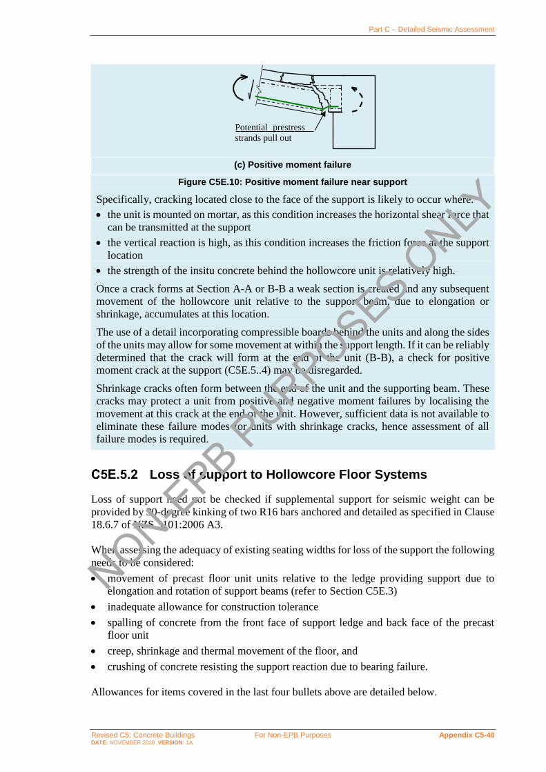
Part C – Detailed Seismic Assessment
Revised C5: Concrete Buildings For Non-EPB Purposes Appendix C5-40 DATE: NOVEMBER 2018 VERSION: 1A
(c) Positive moment failure
Figure C5E.10: Positive moment failure near support
Specifically, cracking located close to the face of the support is likely to occur where:
• the unit is mounted on mortar, as this condition increases the horizontal shear force that
can be transmitted at the support
• the vertical reaction is high, as this condition increases the friction force at the support
location
• the strength of the insitu concrete behind the hollowcore unit is relatively high.
Once a crack forms at Section A-A or B-B a weak section is created and any subsequent
movement of the hollowcore unit relative to the support beam, due to elongation or
shrinkage, accumulates at this location.
The use of a detail incorporating compressible boards behind the units and along the sides
of the units may allow for some movement at within the support length. If it can be reliably
determined that the crack will form at the end of the unit (B-B), a check for positive
moment crack at the support (C5E.5..4) may be disregarded.
Shrinkage cracks often form between the end of the unit and the supporting beam. These
cracks may protect a unit from positive and negative moment failures by localising the
movement at this crack at the end of the unit. However, sufficient data is not available to
eliminate these failure modes for units with shrinkage cracks, hence assessment of all
failure modes is required.
Loss of support to Hollowcore Floor Systems
Loss of support need not be checked if supplemental support for seismic weight can be
provided by 30-degree kinking of two R16 bars anchored and detailed as specified in Clause
18.6.7 of NZS 3101:2006 A3.
When assessing the adequacy of existing seating widths for loss of the support the following
needs to be considered:
• movement of precast floor unit units relative to the ledge providing support due to
elongation and rotation of support beams (refer to Section C5E.3)
• inadequate allowance for construction tolerance
• spalling of concrete from the front face of support ledge and back face of the precast
floor unit
• creep, shrinkage and thermal movement of the floor, and
• crushing of concrete resisting the support reaction due to bearing failure.
Allowances for items covered in the last four bullets above are detailed below.
Potential prestress
strands pull out
NON-EPB P
URPOSES ONLY

Part C – Detailed Seismic Assessment
Revised C5: Concrete Buildings For Non-EPB Purposes Appendix C5-41 DATE: NOVEMBER 2018 VERSION: 1A
Note:
Assessment based on these procedures will result in low ratings for buildings with units
with very short seating, but the assessor is reminded that a minimum score of 15%NBS is
recommended in Section A8.1.
Inadequate allowance for construction tolerance
In general, precast units have been constructed on the short side to reduce problems in
placing the units on supporting beams. In an assessment, ideally the constructed seating
length should be directly measured in the field. Where these measurements are not possible
it is recommended that a construction tolerance of 20 mm be assumed (Bull, 1999). This
gives an initial contact length between the precast floor unit and support ledge of the
dimensioned length of the support ledge minus 20 mm.
Spalling at support
Spalling of unarmoured concrete occurs from both the front of the support ledge as well as
from the back face of the hollowcore units, reducing the contact length available to support
the precast units. Testing of hollowcore units (Jensen, 2007) indicates the spalling from the
back of the unit can occur at very low drifts. This testing also indicates that armouring of
just the ledge does not reduce the total length of spalling (unless accompanied by low friction
bearing strips) as strengthening of the ledge can in fact result in further entrapment of the
unit and larger spalling from the end of the unit.
Potential spalling is dependent on the drift demand as given in Figure C5E.11 below.
Spalling length of may be taken as zero if armouring of the end of the unit and of the ledge
is present.
Figure C5E.11: Total spalling length to be considered for hollowcore units
NON-EPB P
URPOSES ONLY

Part C – Detailed Seismic Assessment
Revised C5: Concrete Buildings For Non-EPB Purposes Appendix C5-42 DATE: NOVEMBER 2018 VERSION: 1A
Note:
A minimum spall depth of 15 mm is recommended regardless of calculated drift demand
due to cracking of end of hollowcore units observed at low drifts in laboratory tests. The
maximum spall length is consistent with that observed in laboratory tests (Jensen, 2007).
Observations from Kaikoura earthquake indicate that spalling of the ledge can still occur
even when low friction strips are used (Henry et al., 2017). It is expected that low friction
strips and debonding of the unit from the supporting beam will reduce the spalling at the
back of the unit, however this improvement in performance is dependent on the position
of the low friction strip, and hence, it is recommended to use the same spalling values as
provided above.
Creep, shrinkage and thermal actions
For practical purposes, it is recommended that the loss in support length due to creep,
shrinkage and thermal strain may be taken as 0.6 mm per metre of length of the precast unit.
Shortening of a precast floor unit due to creep, shrinkage and/or thermal strains may occur
at either or both of the supports. Once a crack has been initiated at one end it is possible that
all the movement in the span will occur at that end. Hence, two limiting cases should be
considered: all the movement occurs at the end, or no movement occurs at the end.
Opening up a crack due to creep and shrinkage movement reduces the shear transfer that can
develop across the crack. This reduces the potential prying action of the hollowcore unit on
the beam. In this situation the reduction in prying action can either reduce or eliminate the
spalling that occurs from the back face of the hollowcore unit.
Note:
In recognition of this action, the calculated movement due to creep, shrinkage and thermal
strain is not added to the loss of length due to spalling. The greater loss in contact length
due to spalling or to creep, shrinkage and thermal strain is assumed to apply.
Bearing failure
Sufficient contact length should remain between each hollowcore unit and the supporting
ledge, after allowance has been made for the loss of supporting length identified above, to
prevent crushing of concrete due to this reaction.
The required bearing area can be calculated from the allowable bearing stress in
NZS 3101:2006, Clause 16.3. In determining bearing area, effective bearing width shall be
based on assuming a 2:1 slope for the spread of gravity stresses in the webs of the hollowcore
units as illustrated in Figure C5E.12, but shall be taken as no less than 5 mm. NON-E
PB PURPOSES O
NLY

Part C – Detailed Seismic Assessment
Revised C5: Concrete Buildings For Non-EPB Purposes Appendix C5-43 DATE: NOVEMBER 2018 VERSION: 1A
Figure C5E.12: Illustration of bearing widths for typical hollowcore section based on assumed 2:1 projection of gravity stresses from minimum web width
Failure in negative moment zones near support
Where the end of the unit is fixed into the support by the topping reinforcement or by other
continuity reinforcement, a negative moment may be induced and cracks can occur. Where
the starter reinforcement has been terminated close to the support, a critical section for
negative flexure may occur at the cut-off point, where the moment capacity reduces over the
development length. The moment demand (𝑇 × 𝑗𝑑) may exceed the moment capacity at that
region. This situation is particularly critical where the starter bars have been lapped to non-
ductile mesh. The flexural capacity must be checked and guidance is provided below.
Note:
Reinforcement connecting the hollowcore unit to a supporting element may be stressed
due to a crack at the back face of a hollowcore unit. In earthquakes wide cracks may be
induced at the supports, and continuity reinforcement connecting the hollowcore units to
their supporting structure may be stressed to close to its ultimate strength.
Hollowcore floors constructed using mesh reinforcement with short starter bars, or
with over-reinforced end connections (e.g. paperclip reinforcement in broken out
cells), are prone to negative flexural failure at the termination of the starter bars (refer to
Figure C5E.13). Tests (Woods et al., 2008) have shown that the use of standard flexural
theory over-estimates negative moment flexural strength due to the stress concentration
and concentrated yielding of the mesh, and this theory needs to be modified as described
below to enable realistic negative moment flexural strength predictions to be made.
Figure C5E.13: Negative moment failure
Starter bars terminate
2:1
NON-EPB P
URPOSES ONLY

Part C – Detailed Seismic Assessment
Revised C5: Concrete Buildings For Non-EPB Purposes Appendix C5-44 DATE: NOVEMBER 2018 VERSION: 1A
(a) Arrangement
Figure C5E.14: Identification of flexural failure in negative moment region (Loading conditions defined in Figure C5E.17)
As shown in Figure C5E.14, flexural failure of a hollowcore unit in negative moment zone
is assessed by comparing the moment coverage (capacity) with the moment demand (due to
induced end moments, dead load, superimposed dead load, and live load) to determine if
failure occurs at the end of the starters.
If the hollowcore unit is inspected and no cracking is identified at the end of the starter bars,
the moment coverage may be calculated using uncracked capacity of the section. If units are
NON-EPB P
URPOSES ONLY

Part C – Detailed Seismic Assessment
Revised C5: Concrete Buildings For Non-EPB Purposes Appendix C5-45 DATE: NOVEMBER 2018 VERSION: 1A
not inspected, moment coverage calculations must assume a cracked section as described
below.
Figure C5E.15: Example of moment coverage at end of hollowcore unit
Moment coverage is determined based on the combination of moment capacity of starter
bars, topping mesh, and prestress strand, allowing for development of each component, as
shown in Figure C5E.15. Development length of the starter bars is based on 2/3rds of the
development length given in NZS 3101:2006, Equation 8-2, using the stress in the
reinforcement taken as equal to 𝑓y. Flexural strength provided by the mesh at the end of the
starters should be calculated at a “first yield” approximation, assuming a strain concentration
factor for the mesh of 𝑆cf (i.e. average limiting strain = peak yield strain/𝑆cf) and a linear
distribution of elastic compression stress in the concrete.
𝑆cf = 4 (ℎ
375) …C5E.6
where:
ℎ = combined hollowcore and topping depth.
Figure C5E.16: Strain and stress profiles for section subjected to negative moment
The peak yield strain may be taken as the 0.2% proof strain combined with the assumed
elastic strain:
휀ym = 0.002 + 𝑓ypm
𝐸m …C5E.7
where:
𝑓ypm = mesh probable yield strength (MPa)
𝐸m = mesh Young’s Modulus (MPa).
휀c
휀p
휀ym/𝑆cf 𝑓ypm
𝑓p
𝑓c
ℎ
NON-EPB P
URPOSES ONLY

Part C – Detailed Seismic Assessment
Revised C5: Concrete Buildings For Non-EPB Purposes Appendix C5-46 DATE: NOVEMBER 2018 VERSION: 1A
In the example above, the prestressing strands are within the compression zone of the section
and will therefore reduce the section bending strength. Therefore the strand stress, 𝑓p, may
be taken as the effective stress in the strand (accounting for losses), 𝑓se, reduced by the elastic
shortening due to flexural compression:
𝑓p = 𝑓se − 휀p𝐸ps …C5E.8
Note:
Woods et al. (2008) demonstrated that flexural theory ignoring tension stiffening will
overestimate the capacity of a cracked hollowcore section with the mesh in tension.
A strain concentration factor of 4 for a 300 mm unit and 75 mm topping is introduced to
account for the tension stiffening effect.
The effective stress in the strand may be taken as 0.8𝑓pi, where 𝑓pi is the stress in the
strand at initial prestress. For typical hollowcore units used in New Zealand from 1980s
onward, 𝑓pi may be assumed to be 65% of the ultimate capacity of the strand, or
0.65*1860 MPa = 1200 MPa.
The moment demands from gravity are determined assuming a simply supported beam.
These moment demands are then adjusted to account for induced actions at the end of the
unit due to beam elongation and rotation. End conditions of floor units will vary considerably
during an earthquake. Two critical loading conditions are considered here:
• Firstly, for a unit supported in the elongation zone, 𝑙e, equal end moments in the floor
are produced by the eccentricity of the applied axial tension through the starter bars (refer
to Figure C5E.17). Tension in the bars is based on assuming bars are yielding to full
overstrength capacity. For this loading condition, the moment coverage must be reduced
to account for axial tension.
• Secondly, for all units (both within and beyond the elongation zone), overstrength
moment at the end of the unit is assumed to develop due to compression between the
bottom of the unit and the support beam balancing the tension in the starter bars. Moment
at the other end of the unit is assumed to be zero (refer to Figure C5E.17).
If the resulting moment diagram is below the moment coverage than Negative Moment
Failure is not applicable (i.e. the units are capacity protected by yielding of the starter bars).
If the moment demand exceeds the moment coverage then the limiting drift is taken as 1%.
Note:
Experimental evidence indicates negative moment failures can occur at drifts at or below
2% for cases where elongation is not imposed (Liew, 2004). Limiting drift of 1% is
selected here to account for the presence of elongation, as well as other factors impacting
the capacity of units in real buildings not accounted for in the experiments including
vertical ground acceleration, torsion of units, etc.
Note that units with paperclip reinforcement in broken out cells are prone to negative
moment failure due to the high capacity, 𝑀o, at the end of the unit. This failure was
observed in tests by Liew (2004).
NON-EPB P
URPOSES ONLY

Part C – Detailed Seismic Assessment
Revised C5: Concrete Buildings For Non-EPB Purposes Appendix C5-47 DATE: NOVEMBER 2018 VERSION: 1A
(a) Loading condition i (only units within elongation zone)
(b) Loading condition ii (all units)
Figure C5E.17: Moments imposed by induced actions at the ends of hollowcore units
Figure C5E.18: Negative moment failure due to supplemental support placed flush with hollowcore unit (a) illustration of failure from Liew (2004); (b) Moment demand due to shifted
reaction; (c) Shear due to shifted reaction.
M-
Hollowcore Strand
Shear Crack
27
𝑀o
𝑉end
𝑉r
𝑀o/𝑉endX
𝑉r
x
NON-EPB P
URPOSES ONLY

Part C – Detailed Seismic Assessment
Revised C5: Concrete Buildings For Non-EPB Purposes Appendix C5-48 DATE: NOVEMBER 2018 VERSION: 1A
As observed in a test by Liew (2004), units retrofitted with supplemental supports placed
flushed against the underside of the unit are also prone to negative moment failures. During
negative bending, the vertical reaction will shift to the end of the supplemental support, thus
shifting the moment diagram and increasing negative moment demand at the end of the
starter bars, as shown in Figure C5E.18. Units with such retrofits should be evaluated
considering load condition (ii) from Figure C5E.17 with moment diagram resulting from
the reaction assumed to develop at the end of the supplemental support as illustrated in
Figure C5E.18. Reaction force, 𝑉r, should be assumed limited by the bending capacity of the
supplemental support. Strong supplemental supports may result in shear failure of end of
hollowcore unit. Any cases identified as likely Negative Moment Failures will be assumed
to have a drift limit of 1%.
Note:
Ideally supplemental supports should be provided by RHS (Jensen, 2007) as the rounded
corners form a pivot point to the soffit of the hollowcore unit. If vulnerable to a Negative
Moment Failure, supplemental supports should be placed with a gap to the hollowcore
unit. Gap size to be selected to avoid prying action against the unit at maximum drift
demand.
Positive moment failure and web cracking
As described in Section C5E.5.1, a positive moment crack is assumed to form if the end of
the unit is trapped and unable to accommodate relative rotation between the beam and the
hollowcore floor. The limiting drift for a positive moment failure is minimum of the drift at
which the positive moment crack exceeds a critical crack width (Section C5E.5. 5) or
development of cracking of the hollowcore webs (Section C5E.5.5). When web cracking is
likely to occur in the section, the presence of transverse cracks (due to positive moment
failure) can lead to catastrophic failure with the bottom section of hollowcore dropping. As
illustrated in the flowchart in Figure C5E.8, such collapse of the bottom section of the
hollowcore can occur even if the positive moment crack does not exceed the critical crack
width.
Transverse cracking due to positive moment failure near a support
The critical limit state for assessment of a positive moment flexural crack in the hollowcore
unit close to the support point is taken as the state which causes the movement of a
hollowcore unit relative to a support point equals to the strand diameter:
Positive Moment Failure: ∆tot = strand diameter
Movement of the hollowcore unit, ∆tot, is determined based on beam elongation and support
beam rotation as defined in Section C5E.3.
Note:
As shown in Figure C5E.10, for units trapped against movement at the support beam (i.e.
without low-friction bearing strips), positive moment demands near a support (resulting
from relative rotation of the unit and the supporting beam) can lead to transverse cracking
NON-EPB P
URPOSES ONLY

Part C – Detailed Seismic Assessment
Revised C5: Concrete Buildings For Non-EPB Purposes Appendix C5-49 DATE: NOVEMBER 2018 VERSION: 1A
in the hollowcore unit. The end of a hollowcore unit is susceptible to the development of
a positive moment crack due to limited compression force from the undeveloped
pretensioning strand in this location. Once the crack gets to a width close to the strand
diameter, the strand will bend and pull out of the crack, which transfers the total shear
force to the topping above the hollowcore unit. This will likely lead to the topping
separating from the hollowcore unit, resulting in collapse.
A strand diameter of 12.5 mm may be assumed if details of the hollowcore unit is
unknown.
Web cracking
If a transverse crack forms at the end of the unit (Section C5E.5.4) and web cracking occurs,
there is a risk the unit or the bottom half of the unit could collapse (regardless of the width
of the transverse crack). Web cracking can occur due to:
• deformation incompatibility between the hollowcore unit and adjacent members
• due to torsion of the unit, or
• shear induced from support rotation
The following sections provide a means of determining the limiting drift due to web
cracking.
Incompatible displacements between hollowcore units and other structural elements
When differential displacement develops between a hollowcore unit and an adjacent beam,
or other structural element, force transfer between the two can be high resulting in
web splitting, which in certain cases can lead to portions of the bottom of the unit falling.
Figures C5E.19 and C5E.20 illustrate common cases where differential displacements may
result in damage to hollowcore units. Other examples include floor slabs connecting two
adjacent concrete walls.
NON-EPB P
URPOSES ONLY

Part C – Detailed Seismic Assessment
Revised C5: Concrete Buildings For Non-EPB Purposes Appendix C5-50 DATE: NOVEMBER 2018 VERSION: 1A
Figure C5E.19: Incompatible displacements between precast floor units and beams (Fenwick et al., 2010)
Figure C5E.20: Incompatible displacements between precast floor units and braced bay (Fenwick et al., 2010)
NON-EPB P
URPOSES ONLY

Part C – Detailed Seismic Assessment
Revised C5: Concrete Buildings For Non-EPB Purposes Appendix C5-51 DATE: NOVEMBER 2018 VERSION: 1A
(a) Current practice (b) Previous practice
Figure C5E.21: Current and previous practice at junction between beams, or other structural elements, and hollowcore units
Figure C5E.22 shows a hollowcore unit adjacent to a reinforced concrete beam. Flexural
deformation of the beams and columns causes differential displacements to develop between
the hollowcore unit and the beam. Three separate components of deformation can be
identified, and these components consist of:
• elastic deformation of the beam
• deformation due to the formation of a plastic hinge in the beam adjacent to the column
face, and
• deflection of the hollowcore unit due to the support points being displaced from the
centre-line of the columns.
Figure C5E.22: Elevation on hollowcore unit adjacent to a beam
The combined elastic deformation of the beam and the deformation due to the formation of
a plastic hinge in the beam adjacent to the column face is defined as 𝛿b, and can be found
using Table C5E.1. Values are given for a range of column depth to beam depth ratios, as
well as span of bay to beam depth ratios. For building conditions not given in Table C5E.1,
interpolation may be used; extrapolated values must be used with caution and it is advised
that calculations instead be undertaken from first principles following the approach
described by Fenwick et al (2010).
The vertical displacement of the hollowcore unit due to rotation of the columns and the offset
of the support point from the column centre-line can be calculated from geometry, using:
𝛿r = 𝜃c𝑠(𝐿/2−𝑠−0.9ℎb)
(𝐿/2−𝑠) …C5E.9
Starter bars
Lap of starter bars to reinforcement in topping above precast unit Linking slab, span
minimum of 6 × 𝑡link 𝑡link
Mesh reinforcement
Linking slab allows beam or other structural element to move relative to hollowcore units
Lack of linking slab causes high forces to be induced between beam and hollowcore unit, which can split webs
s
plastic region ℎb ℎc
𝐿
hollowcore unit plus
75 mm topping
ℎb
NON-EPB P
URPOSES ONLY
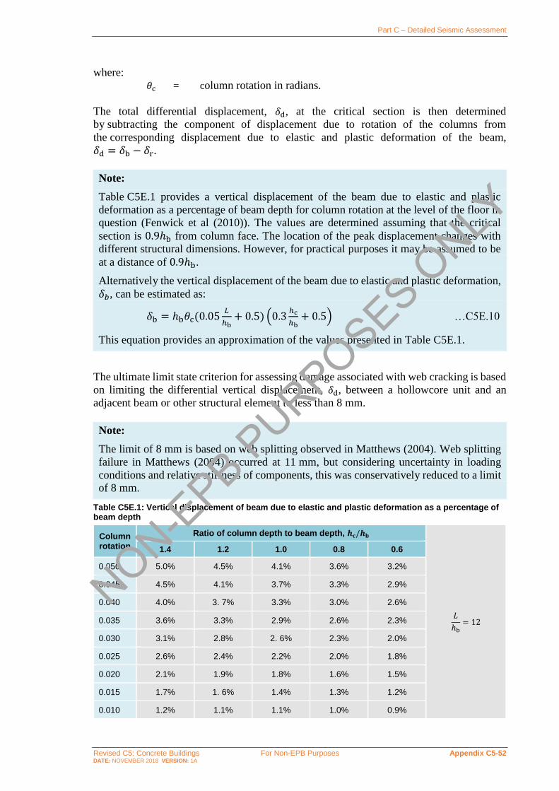
Part C – Detailed Seismic Assessment
Revised C5: Concrete Buildings For Non-EPB Purposes Appendix C5-52 DATE: NOVEMBER 2018 VERSION: 1A
where:
𝜃c = column rotation in radians.
The total differential displacement, 𝛿d, at the critical section is then determined
by subtracting the component of displacement due to rotation of the columns from
the corresponding displacement due to elastic and plastic deformation of the beam,
𝛿d = 𝛿b − 𝛿r.
Note:
Table C5E.1 provides a vertical displacement of the beam due to elastic and plastic
deformation as a percentage of beam depth for column rotation at the level of the floor in
question (Fenwick et al (2010)). The values are determined assuming that the critical
section is 0.9ℎb from column face. The location of the peak displacement changes with
different structural dimensions. However, for practical purposes it may be assumed to be
at a distance of 0.9ℎb.
Alternatively the vertical displacement of the beam due to elastic and plastic deformation,
𝛿𝑏, can be estimated as:
𝛿b = ℎb𝜃c(0.05𝐿
ℎb+ 0.5) (0.3
ℎc
ℎb+ 0.5) …C5E.10
This equation provides an approximation of the values presented in Table C5E.1.
The ultimate limit state criterion for assessing damage associated with web cracking is based
on limiting the differential vertical displacement, 𝛿d, between a hollowcore unit and an
adjacent beam or other structural element to less than 8 mm.
Note:
The limit of 8 mm is based on web splitting observed in Matthews (2004). Web splitting
failure in Matthews (2004) occurred at 11 mm, but considering uncertainty in loading
conditions and relative stiffness of components, this was conservatively reduced to a limit
of 8 mm.
Table C5E.1: Vertical displacement of beam due to elastic and plastic deformation as a percentage of beam depth
Column rotation
Ratio of column depth to beam depth, 𝒉𝐜/𝒉𝐛
𝐿
ℎb= 12
1.4 1.2 1.0 0.8 0.6
0.050 5.0% 4.5% 4.1% 3.6% 3.2%
0.045 4.5% 4.1% 3.7% 3.3% 2.9%
0.040 4.0% 3. 7% 3.3% 3.0% 2.6%
0.035 3.6% 3.3% 2.9% 2.6% 2.3%
0.030 3.1% 2.8% 2. 6% 2.3% 2.0%
0.025 2.6% 2.4% 2.2% 2.0% 1.8%
0.020 2.1% 1.9% 1.8% 1.6% 1.5%
0.015 1.7% 1. 6% 1.4% 1.3% 1.2%
0.010 1.2% 1.1% 1.1% 1.0% 0.9%
NON-EPB P
URPOSES ONLY

Part C – Detailed Seismic Assessment
Revised C5: Concrete Buildings For Non-EPB Purposes Appendix C5-53 DATE: NOVEMBER 2018 VERSION: 1A
Column rotation
Ratio of column depth to beam depth, 𝒉𝐜/𝒉𝐛
𝐿
ℎb= 10
1.4 1.2 1.0 0.8 0.6
0.050 4.6% 4.2% 3.8% 3.4% 3.0%
0.045 4.2% 3.8% 3.5% 3.1% 2.7%
0.040 3.8% 3.4% 3.1% 2.8% 2.4%
0.035 3.3% 3.0% 2.7% 2.5% 2.2%
0.030 2.9% 2.6% 2.4% 2.1% 1. 9%
0.025 2.4% 2.2% 2.0% 1.8% 1.6%
0.020 2.0% 1.8% 1.7% 1.5% 1.3%
0.015 1.5% 1.4% 1.3% 1.2% 1.1%
0.010 1.1% 1.0% 1.0% 0.9% 0. 8%
Column rotation
Ratio of column depth to beam depth, 𝒉𝐜/𝒉𝐛
𝐿
ℎb= 8
1.4 1.2 1.0 0.8 0.6
0.050 4.3% 3.9% 3.6% 3.2% 2.79%
0.045 3.9% 3.6% 3.2% 2.9% 2.5%
0.040 3.5% 3.2% 2.9% 2.6% 2.3%
0.035 3.1% 2.8% 2.5% 2.3% 2.0%
0.030 2.6% 2.4% 2. 0% 2.0% 1.7%
0.025 2.2% 2.0% 1.9% 1.7% 1.5%
0.020 1.9% 1.7% 1.5% 1.4% 1.2%
0.015 1.4% 1.3% 1.2% 1.1% 1.0%
0.010 1.0% 0.9% 0.8% 0.8% 0.7%
Column rotation
Ratio of column depth to beam depth, 𝒉𝐜/𝒉𝐛
𝐿
ℎb= 6
1.4 1.2 1.0 0.8 0.6
0.050 4.2% 3.8% 3. 5% 3.1% 2.7%
0.045 3.8% 3.5% 3.1% 2.8% 2.4%
0.040 3.4% 3.1% 2.8% 2.5% 2.2%
0.035 3.0% 2.7% 2.4% 2.2% 1.9%
0.030 2.5% 2.3% 2.10% 1.9% 1.6%
0.025 2.1% 2.0% 1.8% 1.6% 1.4%
0.020 1.7% 1. 6% 1.4% 1.3% 1.1%
0.015 1.3% 1.2% 1.1% 1.0% 0.9%
0.010 0.9% 0.8% 0.7% 0.7% 0.6%
NON-EPB P
URPOSES ONLY

Part C – Detailed Seismic Assessment
Revised C5: Concrete Buildings For Non-EPB Purposes Appendix C5-54 DATE: NOVEMBER 2018 VERSION: 1A
Column rotation
Ratio of column depth to beam depth, 𝒉𝐜/𝒉𝐛
𝐿
ℎb= 4
1.4 1.2 1.0 0.8 0.6
0.050 3.2% 3.0% 2.8% 2.6% 2.3%
0.045 2.9% 2.7% 2.5% 2.3% 2.1%
0.040 2.6% 2.4% 2.2% 2.0% 1.8%
0.035 2.3% 2.1% 2.0% 1.8% 1.6%
0.030 1.9% 1.8% 1.7% 1.5% 1.4%
0.025 1.6% 1.5% 1.41% 1.3% 1.2%
0.020 1.3% 1.2% 1.1% 1.0% 0.9%
0.015 1.0% 0.9% 0.9% 0.8% 0.7%
0.010 0.7% 0.6% 0.6% 0.5% 0.5%
Torsion induced in hollowcore units
Hollowcore units with concrete topping predominately resist torsion by a shear flow in the
outside webs, the soffit slab and the concrete topping. This behaviour is similar to that of a
box section and results in a high torsional stiffness. Differential deflection of supports at the
ends of hollowcore units can induce compatibility torsion issues in hollowcore units. While
the torsional strength itself is not important, it is essential to limit the twist so that the flexural
and shear capacities of the hollowcore units are not significantly reduced by diagonal
cracking associated with torsion. Cracking due to torsion will result in cracking of the webs,
thus impacting gravity load support for units already sustaining transverse cracking through
the bottom flange of the hollowcore unit.
Note:
Evidence from recent earthquakes has indicated that most units will typically have some
flexibility in the support conditions which can limit the torsional demands in units making
the assessment process described below overly conservative in many typical cases.
However, it is important to assess the likelihood of torsional cracking in cases with
significant relative rotation of the two ends of the unit. Examples where torsion should be
considered include, but are not limited to:
• One end of unit supported on link of eccentrically braced frame
• One end of unit supported on cantilever (e.g. Figure C5E.23)
• One end of unit supported on coupling beam
• One end of unit supported on wall, with other end supported on frame
• Or any cases identified as likely inducing significant torsion. NON-EPB P
URPOSES ONLY

Part C – Detailed Seismic Assessment
Revised C5: Concrete Buildings For Non-EPB Purposes Appendix C5-55 DATE: NOVEMBER 2018 VERSION: 1A
(a) Plan on corner of frame building without corner columns
(b) Torsion induced in hollowcore unit close to corner
Figure C5E.23: Torsional actions induced by compatibility in a hollowcore floor
The limit for assessing the ultimate limit state for torsion in hollowcore floors is taken as the
larger of:
• 2.5 times the twist corresponding to that sustained at the nominal cracking torque
(𝜃crack), or
• the maximum torsional rotation sustained by the insitu concrete topping, plus the
minimum depth of concrete to the top of the voids in the hollowcore unit, when this
depth of concrete is assumed to act as a beam without torsional reinforcement (i.e. at 𝑇o
from NZS 3101:2006). Based on this assumption the maximum level of twist can be
calculated for a member without torsional reinforcement.
Assess the torsional cracking of the hollowcore unit with insitu concrete topping at the
critical location in the section. Based on the limiting shear stress, the nominal cracking torque
(𝑇crack) is determined, and an associated torsional rotation (𝜃crack) at which cracking in the
webs occurs.
Torsional calculations are based on an equivalent tube, with an area of 𝐴co, where the shear
stress in the wall of the tube is assumed to be uniform (for example, Figure C5E.24). The
maximum wall thickness of the equivalent tube (𝑡c) is equal to the smaller of 0.75𝐴co/𝑃c or
the actual wall thickness, where 𝑝c is the perimeter of area 𝐴co.
This procedure assumes that the internal webs are taking shear without torsion, thus do
not need to consider torsion-shear interaction.
Note, that in hollowcore units, the soffit slab thickness varies with a minimum thickness
below the ducts that should be used for assessing the torsional cracking stress. However,
at other locations in the soffit the effective thickness is greater than this minimum value.
Assuming the minimum thickness everywhere, would under-assess the effective torsional
Torsion
Torsion
Pin joint
Corner rises and falls due to drift on both axes and this induces
torsion in units H1 and H2
H1 H2
NON-EPB P
URPOSES ONLY

Part C – Detailed Seismic Assessment
Revised C5: Concrete Buildings For Non-EPB Purposes Appendix C5-56 DATE: NOVEMBER 2018 VERSION: 1A
stiffness. To allow for this effect, the wall of the tube representing the soffit should be
increased for stiffness calculations and a slightly higher average value should be used for
this purpose. It is suggested that an additional value of 10 mm is used to increase the tube
thickness. Dimensions vary between individual units and considerable differences exist
with different forms of hollowcore unit.
The limiting shear stress, 𝑣tn, is defined by the principal tensile stress at the critical location
which is where the thickness is a minimum.
𝑣tn = min {𝑓dt√1 +𝑓pc
𝑓ct; 0.2𝑓’c; 10MPa} …C5E.11
where 𝑓ct is the direct tensile strength of concrete and 𝑓pc is taken as the longitudinal prestress
at the critical location which may be assumed equal to 1/3 of the effective stress in the strand
after long term loss has occurred (i.e. 𝑓pc = 𝑓se/3). The effective stress in the strand may be
taken as 0.8𝑓pi, where 𝑓pi is the stress in the strand at initial prestress. For typical hollowcore
units used in New Zealand from 1980s onward, 𝑓pi may be assumed to be 65% of the ultimate
capacity of the strand, or 0.65*1860 MPa = 1200 MPa.
The torsional shear flow, 𝑞, is found from 𝑣tn × 𝑡min, using the minimum wall thickness
(typically the bottom flange, e.g. 25 mm in Figure C5E.24). The nominal cracking torque
(𝑇crack) is given by:
2𝐴co𝑞 = 2𝑞𝑏t𝑑t = 𝑇crack …C5E.12
where:
𝐴co = area enclosed by the equivalent tube (refer to example in
Figure C5E.24).
(a) Shear flow in section (b) Thin tube analogy for unit and topping
Figure C5E.24: Example equivalent tube for assessing torsional cracking
The twist over the length of the unit corresponding to torsional cracking is determined from
the torsional stiffness of the section. The stiffness can be calculated by equating the internal
strain energy to the work done by the external forces, noting that for calculating stiffness in
the soffit and webs, the shear stress is based on an average value for thickness rather than
the minimum thickness (e.g. 35 mm in Figure C5E.24). The energy from the external forces
is equal to ½ 𝑇𝜃, where 𝜃 is the angle of twist over the length being considered. The internal
𝑏t=
𝑑t=
NON-EPB P
URPOSES ONLY

Part C – Detailed Seismic Assessment
Revised C5: Concrete Buildings For Non-EPB Purposes Appendix C5-57 DATE: NOVEMBER 2018 VERSION: 1A
energy is equal to the summation of the strain energy associated with the shear deformation
around the section, Σ½𝑣𝛾, where 𝑣 is the shear stress, and 𝛾 is the shear strain.
The internal strain energy is calculated for each of the top, the webs and the soffit of the
units. The shear strain is determined from the shear stress at that location divided by the
shear modulus of concrete (G), which is taken as 0.4𝐸c. Hence, the internal strain energy
over the hollowcore unit length is given by:
𝐸ε =1
2 𝐿 ∑ (
𝑞
𝑡i) 𝑡i𝑤i𝛾i …C5E.13
where the sum is over the four sides of the equivalent tube, 𝐿 = length of the hollowcore
unit, 𝑡i and 𝑤i are the thickness and width of the flanges and webs, and 𝛾i = (𝑞
𝑡i) 0.4𝐸𝑐i⁄ is
the shear strain in the flanges and webs. From this twist resulting in cracking of webs can be
determined.
C5E.6 Inter-storey Drift Capacity of Double-Tee Floor Systems
General
Precast double-tee units can be supported either on the flange or web, and for both types a
critical failure due to loss of seating length needs to be checked. Flange hung double-tee
units in existing New Zealand buildings were predominantly detailed using the “loop bar”
(or “pig-tail”) support detail. For flange-hung units, an additional check needs to be made
for a flexural failure at end of supporting flange (refer to Figure C5E.25).
Figure C5E.25: Procedure for determining inter-storey drift capacity of double-tee floor systems
This section assumes a double-tee unit contains shear reinforcement and thus is typically not
susceptible to negative moment failure. An assessment process similar to that recommended
for hollowcore in Section C5E.5.2 should be followed if shear reinforcement is not present.
When considering vulnerability to negative moment failure, bear in mind the shifting of the
reaction for cases with retrofit support angles (as illustrated in Figure C5E.18 for
hollowcore).
NON-EPB P
URPOSES ONLY

Part C – Detailed Seismic Assessment
Revised C5: Concrete Buildings For Non-EPB Purposes Appendix C5-58 DATE: NOVEMBER 2018 VERSION: 1A
Furthermore, web-supported double-tee units with webs trapped in cast-in-place concrete
from supporting beam should be assessed for positive moment failure using a method similar
to that recommended for ribs in Section C5E.7.3.
Loss of support to Double-Tee Floor Systems
Overview
Loss of seating for the support of double-tee units is determined in much the same way as
for hollowcore, with the following considerations:
• movement of precast floor units relative to the ledge providing support due to elongation
and rotation of support beams, (refer to Section C5E.3)
• inadequate allowance for construction tolerance
• spalling of concrete from the front face of support ledge
• spalling of concrete at the back face of the precast floor unit
• creep, shrinkage and thermal movement of the floor, and
• crushing of concrete resisting the support reaction due to bearing failure.
Allowances for items covered in the last five bullets above are detailed below.
Inadequate allowance for construction tolerance
Where possible, the construction tolerance should be measured. Where these measurements
are not available it is recommended that a construction tolerance of 20 mm is assumed
(Bull, 1999). This gives an initial contact length between the precast floor unit and support
ledge of the dimensioned length of the support ledge minus 20 mm.
Spalling at support
Potential spalling from the supporting ledge, 𝑠𝑝𝑎𝑙𝑙ledge, and spalling from the back face of
the supported unit, 𝑠𝑝𝑎𝑙𝑙unit, is dependent on the drift demand as given in Figure C5E.26.
The total reduction in available seating due to spalling is the sum of 𝑠𝑝𝑎𝑙𝑙ledge. and 𝑠𝑝𝑎𝑙𝑙unit.
NON-EPB P
URPOSES ONLY

Part C – Detailed Seismic Assessment
Revised C5: Concrete Buildings For Non-EPB Purposes Appendix C5-59 DATE: NOVEMBER 2018 VERSION: 1A
Figure C5E.26: Spalling depths to be considered for flange-hung and web-supported double-tee units
The maximum spall at the end of the unit should be taken as equal to the cover depth to the
first reinforcing bar plus 10 mm (this is shown as typical case of 35 mm in Figure C5E.26,
but may vary depending on the cover to first bar). The maximum spall from the supporting
ledge shown in Figure C5E.26 need not exceed the depth to the longitudinal bar in the
supporting ledge.
Spalling of unit may be taken as zero if armouring of the end of the unit is present. Spalling
of ledge may be taken as zero if armouring of ledge is present.
Note:
Spalling of unarmoured concrete occurs from both the front of the support ledge as well
as from the back face of double-tee units, reducing the contact length available to support
the precast units. The width of the bearing area is more concentrated than that of
hollowcore units. This applies for flange-hung as well as web-supported double tees
because the support of gravity load is concentrated in line with the stiff webs. This
concentration of bearing can lead to a more significant prying action at the support (refer
to Figure C5E.27), resulting in a loss of seating. Based on evidence from recent
earthquakes, spalling for both flange and web supported double-tees can occur at lower
drift demands and spalling can be greater than that observed for hollowcore.
In double-tee units, the first reinforcing bar from the end of the unit has a propensity to
act as a stress raiser and generate a crack at that location. For a flange-hung double-tee
unit with a loop bar detail, the crack will tend to form at the loop bar as shown in
Figure C5E.28. This crack will typically extend downward on an incline (as illustrated in
Figure C5E.28), making the total reduction in seating due to the crack at end of unit
slightly larger than the depth to the first reinforcing bar. Consequently, the loss of support
at the end of the unit due to unit spalling is taken as the cover depth to the first bar plus
10 mm.
Cover to first bar plus 10 mm
NON-EPB P
URPOSES ONLY

Part C – Detailed Seismic Assessment
Revised C5: Concrete Buildings For Non-EPB Purposes Appendix C5-60 DATE: NOVEMBER 2018 VERSION: 1A
Figure C5E.27: Demonstration of prying action at end of web-supported double-tee unit
Figure C5E.28: Development of unit and ledge spalling for flange-hung unit with loop bar detail (MBIE 2017)
NON-EPB P
URPOSES ONLY

Part C – Detailed Seismic Assessment
Revised C5: Concrete Buildings For Non-EPB Purposes Appendix C5-61 DATE: NOVEMBER 2018 VERSION: 1A
Creep, shrinkage and thermal actions
Shortening of a precast floor unit due to creep, shrinkage and/or thermal strains may occur
at either or both of the supports. Once a crack has been initiated at one end it is possible that
all the movement in the span will occur at that end. Hence, two limiting cases should be
considered: all the movement occurs at the end, or no movement occurs at the end.
Opening up a crack due to creep and shrinkage movement reduces the shear transfer that can
develop across the crack. This reduces the potential prying action of the unit on the beam. In
this situation the reduction in prying action can either reduce or eliminate the spalling that
occurs from the back face of the double-tee unit.
Note:
In recognition of this action, the calculated movement due to creep, shrinkage and thermal
strain is not added to the loss of length due to spalling. The greater loss in contact length
due to spalling or to creep, shrinkage and thermal strain is assumed to apply.
For practical purposes, it is recommended that the loss in support length due to creep,
shrinkage and thermal strain may be taken as 0.6 mm per metre of length of the double-tee
unit.
Bearing failure
Sufficient contact length should remain between each double-tee unit and the supporting
ledge, after allowance has been made for the loss of supporting length identified above, to
prevent crushing of concrete due to this reaction. Bearing width for flange-hung double tees
should be considered equal to the web width due to concentration of load in line with stiff
webs.
Precast tee units are supported over a shorter width than hollowcore units, and consequently
the bearing stress on the support may be much higher. The required bearing area can be
calculated from the allowable bearing stress in NZS 3101:2006, Clause 16.3.
Failure of flange-hung double-tee floor units
When assessing the capacity of a precast floor unit, a potential failure mode at the point
where the overhanging flange intersects with the web (the “bird’s mouth”), needs to be
considered.
A flexural failure at end of supporting flange is caused by movement of the reaction load
toward end of unit due to beam elongation and friction force developed due to this movement
(Figure C5E.29). Delamination is likely to occur for units supported within the elongation
zone; thus, for such units only the depth of the precast portion of supporting flange
(𝑡 − 𝑡topping in Figure C5E.29) should be considered when following the steps below.
The steps for checking this failure mode are as follows:
Step 1 Determine the probable flexural capacity where the supporting flange transitions
to full depth. Flexural capacity must account for tension shift due to angle of
NON-EPB P
URPOSES ONLY
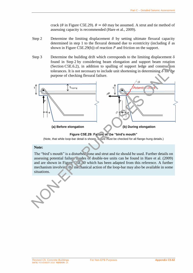
Part C – Detailed Seismic Assessment
Revised C5: Concrete Buildings For Non-EPB Purposes Appendix C5-62 DATE: NOVEMBER 2018 VERSION: 1A
crack (𝜃 in Figure C5E.29). 𝜃 = 60 may be assumed. A strut and tie method of
assessing capacity is recommended (Hare et al., 2009).
Step 2 Determine the limiting displacement 𝛿 by setting ultimate flexural capacity
determined in step 1 to the flexural demand due to ecentricity (including 𝛿 as
shown in Figure C5E.29(b)) of reaction 𝑃 and friction on the support.
Step 3 Determine the building drift which corresponds to the limiting displacement
found in Step 2by considering beam elongation and support beam rotation
(Section C5E.6.2), in addition to spalling of support ledge and construction
tolerances. It is not necessary to include unit shortening in determining 𝛿for the
purpose of checking flexural failure.
(a) Before elongation (b) During elongation
Figure C5E.29: Failure at the “bird’s mouth”
(Note, that while loop-bar detail is shown, failure must be checked for all flange-hung details.)
Note:
The “bird’s mouth” is a disturbed zone and strut and tie should be used. Further details on
assessing potential failure modes of double-tee units can be found in Hare et al. (2009)
and are shown in Figure C5E.30 which has been adapted from this reference. A further
mechanism involving the mechanical action of the loop-bar may also be available in some
situations.
NON-EPB P
URPOSES ONLY

Part C – Detailed Seismic Assessment
Revised C5: Concrete Buildings For Non-EPB Purposes Appendix C5-63 DATE: NOVEMBER 2018 VERSION: 1A
(a) Flexural failure (b) Separation of flanges (in-
situ and/or precast concrete) from web
(c) Shear failure in flange cantilever
(d) Diagonal tension failure (e) Bond failure (f) Separation of flange and web
Figure C5E.30: Potential Failures modes at the “bird’s mouth (from Hare et al (2009))
C5E.7 Inter-storey Drift Capacity of Rib and Infill Floors
General
Note:
There are three variations of the “prestressed rib and infill” floor systems used in
New Zealand. All three systems where developed by the predecessor companies of today’s
Stahlton Engineered Concrete, a division of Fulton Hogan Ltd.
1963-1976: Ribs were formed by 300 mm by 150 mm fired clay tiles placed on a
stressing bed, with prestress wires placed, stressed and finally grouted in to
the clay tiles. On transfer of the prestress force from the wire to the ribs, the
ribs were cut to length. The prestressed ribs were placed on props, supported
at each end by beams or walls. Hollow (cellular) clay tile infill blocks were
placed between the ribs. Cast-in-place concrete topping was then placed on
the ribs and infill blocks to form the floor.
1976-1988: At the beginning this period fired clay floor components were replaced by
concrete prestressed ribs and concrete infill blocks.
1988-today: Due to supply issues with the concrete infill blocks, necessity drove the
alternative of timber infills. Concrete ribs, timber infills and cast-in-place
concrete topping forms the most comment rib and infill system found in
buildings today.
The following section focuses on the common rib and timber infill system, but some words
of caution are important for the systems used between 1963 and 1988.
NON-EPB P
URPOSES ONLY

Part C – Detailed Seismic Assessment
Revised C5: Concrete Buildings For Non-EPB Purposes Appendix C5-64 DATE: NOVEMBER 2018 VERSION: 1A
The fired clay rib and infill system poses an increased risk of general and localised falling
of sections of the underside of the floor.
The anchorage of the indented prestessing wires relies on the grouting of the wires in to
small slots in the fired clay rib (a flat slab, in effect). The topping concrete is placed on to
the ribs (which are extensively propped to take the construction loads). The lack of
reliability of the connection between the wires, grout, to the clay rib and across the cold
joint between the prestressed clay rib and topping concrete is of concern. Damage at the
ends of the ribs will cause loss of bond of the wires and significant reduction of gravity
support of the floor in that zone of damage.
The geometries of the clay elements with thin walled sections and the brittle nature of
fired clay means that the deformations imposed on a floor diaphragm will crack the clay
elements with relative less likelihood of load sharing and redistribution of forces within
the clay infills. The infill blocks will be a significant fall hazard.
The drift capacity of rib and timber infill floors differs from hollowcore floors in that not all
of the identified failure modes are applicable. The increased flexibility of rib and timber
infill floors in comparison to hollowcore units means that the failure modes resulting from
the stiff, box sectional behaviour of hollowcore units (failure due to incompatible
displacements and torsional failure) do not need to be considered.
The presence of shear reinforcement between the ribs and insitu slab may also allow for
a reliable secondary load path after failure of a limited number of ribs has initiated (refer to
Figure C5E.31). These secondary load paths include the catenary action of kinked starter
bars bearing on the rib stirrups and load sharing between adjacent ribs. These secondary load
paths are considered reliable as delamination from the insitu slab is less likely to occur for
ribs where transverse reinforcement provides a better connection between the insitu topping
and the unit compared to either hollowcore or double tees. Such connection is not available
in hollowcore, double tees, or ribs without stirrups extending into the insitu topping, and
hence reliable secondary load paths are only considered for assessment of ribs with stirrups
at the ends of the units.
Guidance regarding assessment of the secondary load paths is provided below.
NON-EPB P
URPOSES ONLY

Part C – Detailed Seismic Assessment
Revised C5: Concrete Buildings For Non-EPB Purposes Appendix C5-65 DATE: NOVEMBER 2018 VERSION: 1A
Figure C5E.31: Procedure for determining inter-storey drift capacity of rib and timber systems
Secondary load path through continuity reinforcement
If sufficient capacity can be established by the continuity reinforcement bars bearing on
stirrups placed within the rib and insitu slab, a secondary load path can be established by the
kinking of the continuity bars (refer to Figure C5E.32). For the continuity reinforcement to
provide a reliable secondary load path, the bars may kink to a maximum angle of 30 degrees
and the shear force due to gravity loads (as considered in seismic load case) must therefore
not exceed one half of the factored tensile capacity of the continuity reinforcement bar
enclosed within the stirrups.
Note:
It is relatively uncommon for the continuity reinforcement to be enclosed in the rib
stirrups. To rely on this secondary load path, this arrangement of the continuity
reinforcement must be confirmed in the field by scanning the floor to identify the layout
of the reinforcement.
Where support is provided by this secondary load path, a limiting drift need not be
considered due to seating loss, or positive moment failure. Note that negative moment failure
NON-EPB P
URPOSES ONLY

Part C – Detailed Seismic Assessment
Revised C5: Concrete Buildings For Non-EPB Purposes Appendix C5-66 DATE: NOVEMBER 2018 VERSION: 1A
must still be assessed. Strain demands on the continuity reinforcement due to elongation
should be considered when assessing if this mechanism is reliable.
Kinking of the continuity reinforcement is not able to provide a reliable load path if the
continuity reinforcement does not pass through stirrups in the rib, since, in such cases,
continuity bars are susceptible to ripping out of the insitu slab concrete.
Figure C5E.32: Secondary gravity load path through kinking of continuity reinforcement (only when continuity reinforcement passes through hooks of rib transverse reinforcement)
Secondary load path due to load sharing between ribs
For rib and timber infill floors where the continuity reinforcement is unable to act as a
hanger, vertical support for the floor may still be possible as a result of load sharing between
one or more ribs. For this support mechanism to be relied upon, the ribs must be adequately
anchored into the insitu slab by the stirrups at the ends of the rib.
To assess this secondary load path all ribs within the “elongation zone” (as defined in
Section C5E.3) are assumed to have lost support (or experience positive or negative moment
failures). The number of ribs supported within the elongation zone is compared to the
number of ribs that are able to have the support removed without resulting in collapse of the
floor based on the capacity of the insitu slab to transmit seismic gravity loading by a
combination of two-way spanning and catenary action between the parallel beam and the
first active rib. This support mechanism is most likely to be achievable where:
• the elongation zone is small, and
• the rib depth (and therefore support reaction) is small.
Where support is provided by this secondary load path, a limiting drift need not be
considered due to all failure modes (i.e. seating loss, positive moment failure, or negative
moment failure).
Loss of support to Rib and Timber Infill Floor Systems
Overview
Loss of seating can be determined similarly to hollowcore, with the following
considerations:
• movement of precast floor units relative to the ledge providing support due to elongation
and rotation of support beams (refer to Section C5E.3)
NON-EPB P
URPOSES ONLY

Part C – Detailed Seismic Assessment
Revised C5: Concrete Buildings For Non-EPB Purposes Appendix C5-67 DATE: NOVEMBER 2018 VERSION: 1A
• allowance for construction tolerances
• spalling of concrete from the front face of support ledge
• unit shortening (spalling of concrete at the back face of the precast rib) due to entrapment
of the precast rib
• creep, shrinkage and thermal movement of the floor, and
• crushing of concrete resisting the support reaction due to bearing failure.
Allowances for items covered in the last five bullets above are detailed below.
Inadequate allowance for construction tolerance
Where possible, the construction tolerance should be measured. Where these measurements
are not available it is recommended that a construction tolerance of 15 mm is assumed. This
gives an initial contact length between the precast rib and support ledge of the dimensioned
length of the support ledge minus 15 mm.
Note:
Suggested construction tolerance value is taken as smaller than that used for hollowcore
and double tee due to ease of installation of lighter ribs and general sense of better quality
control.
Spalling
Ledge and unit spalling for ribs can be assumed to be the same as for hollowcore units in
Figure C5E.11.
Spalling of unit may be taken as zero if armouring of the end of the unit is present. Spalling
of ledge may be taken as zero if armouring of the end of ledge is present.
Note:
As for double-tee units, the width of the seating area of ribs is more concentrated than that
for hollowcore units, which may lead to a more significant prying action at the support
when compared with hollowcore.
Ribs encased in insitu concrete are likely to experience failure within the trapped
end of the unit. Corney (2017) has shown that an inclined failure plane, as shown in
Figure C5E.33, is likely to develop such that the unit is wedged between the support
beams, reducing the likelihood of unit falling. To account for this improved performance,
the spalling lengths for haunched infills are taken as half of the values used for double
tees. NON-EPB P
URPOSES ONLY

Part C – Detailed Seismic Assessment
Revised C5: Concrete Buildings For Non-EPB Purposes Appendix C5-68 DATE: NOVEMBER 2018 VERSION: 1A
Figure C5E.33: Spalling due to rib entrapment (Corney, 2017)
Creep, shrinkage and thermal actions
Shortening of a precast floor unit due to creep, shrinkage and/or thermal strains may occur
at either or both of the supports. Once a crack has been initiated at one end it is possible that
all the movement in the span will occur at that end. Hence, two limiting cases should be
considered: all the movement occurs at the end, or no movement occurs at the end.
Opening up a crack due to creep and shrinkage movement reduces the shear transfer that can
develop across the crack. This reduces the potential prying action of the unit on the beam. In
this situation the reduction in prying action can either reduce or eliminate the spalling that
occurs from the back face of the rib.
Note:
In recognition of this action, the calculated movement due to creep, shrinkage and thermal
strain is not added to the loss of length due to spalling. The greater loss in contact length
due to spalling or to creep, shrinkage and thermal strain is assumed to apply.
For practical purposes, it is recommended that the loss in support length due to creep,
shrinkage and thermal strain may be taken as 0.6 mm per metre of length of the rib.
Bearing failure
Sufficient contact length should remain between each rib and the supporting ledge, after
allowance has been made for the loss of supporting length due to each factor identified
above, to prevent crushing of concrete due to this reaction.
The required bearing area can be calculated from the allowable bearing stress in
NZS 3101:2006, Clause 16.3.
Positive moment rib failure near support
Positive moment cracks in precast ribs can be assessed similarly to those in hollowcore
units (refer to Section C5E.5. 4) and should be assumed to form where the rib is not seated
on top of a low-friction bearing strip and the end of the rib is encased in insitu concrete
at the support. Due to typical spacing of transverse reinforcement in ribs, it should be
assumed that rib shear reinforcement will not cross the positive moment crack (refer to
Figure C5E.34.
NON-EPB P
URPOSES ONLY

Part C – Detailed Seismic Assessment
Revised C5: Concrete Buildings For Non-EPB Purposes Appendix C5-69 DATE: NOVEMBER 2018 VERSION: 1A
Positive moment rib cracks shall be assessed in the same manner as for a hollowcore unit.
The positive moment crack width is estimated based on beam elongation and support beam
rotation as defined in Section C5E.3. The critical crack width is taken equal to the strand
diameter.
Note:
As with hollowcore units, cracking located close to the face of the support is most likely
to occur where:
• the unit is mounted on mortar, as this increases the horizontal shear force that can be
transmitted at the support
• the vertical reaction is high, as this increases the friction force at the support location,
and
• the strength of the insitu concrete surrounding the rib is high.
Figure C5E.34: Positive moment crack in rib
Positive moment rib cracks do not form where the rib can slide on the support without
significant resistance. For this to be assumed, the rib must be seated on top of a low-friction
bearing strip and the sides of the ribs must not be encased into the support, as specified in
NZS 3101:2006.
Negative moment failure near support
As for hollowcore units, reinforcement connecting a precast rib to its supporting element
may be stressed due to cracking at the back face of the rib, and a negative moment failure
may be initiated in floors where the capacity of the continuity reinforcement is significant
and terminates sufficiently close to the support. Although cracking at the critical negative
moment section will potentially propagate through the rib shear reinforcement (if these
stirrups are located in proximity to the critical section), this should not be relied upon to
provide support as the propagation of the crack through the ribs is unpredictable. The method
described in Section C5E.5.3 for hollowcore may be used for ribs.
C5E.8 Inter-storey Drift Capacity of Flat Slab Floors
General
As with rib and timber infill floors, the drift capacity of flat slabs floors differs from
hollowcore floors in that not all of the identified failure modes are applicable. The shorter
spans and shallower depths in comparison to hollowcore units means that the failure modes
NON-EPB P
URPOSES ONLY

Part C – Detailed Seismic Assessment
Revised C5: Concrete Buildings For Non-EPB Purposes Appendix C5-70 DATE: NOVEMBER 2018 VERSION: 1A
resulting from the stiff, box sectional behaviour of hollowcore units (failure due to
incompatible displacements and torsional failure) do not need to be considered.
* Loss of Seating need not be checked if supplemental support for seismic weight can be provided
by 30-degree kinking of two R16 bars anchored as specified in Clause 18.6.7 of NZS 3101:2006 A3
** For supports with low-friction bearing strips designed to Amendment 3 to NZS 3101:1995 (published in April 2004) , positive moment crack can be assumed to be suppressed and checks for web splitting and positive moment crack width can be ignored.
Figure C5E.35C5E.35C5E.35C5E.35C5E.35C5E.35: Procedure for determining inter-storey drift capacity of flat slab systems
Loss of support to Flat Slab Systems
Overview
Loss of seating can be determined similarly to hollowcore, with the following
considerations:
• movement of precast floor units relative to the ledge providing support due to elongation
and rotation of support beams (refer to Section C5E.3)
• allowance for construction tolerances
• spalling of concrete from the front face of support ledge
• unit shortening (spalling of concrete at the back face of the precast unit) due to
entrapment of the precast slab
• creep, shrinkage and thermal movement of the floor, and
NON-EPB P
URPOSES ONLY

Part C – Detailed Seismic Assessment
Revised C5: Concrete Buildings For Non-EPB Purposes Appendix C5-71 DATE: NOVEMBER 2018 VERSION: 1A
• crushing of concrete resisting the support reaction due to bearing failure.
Allowances for items covered in the last five bullets aboveare detailed below.
Inadequate allowance for construction tolerance
Where possible, the construction tolerance should be measured. Where these measurements
are not available it is recommended that a construction tolerance of 15 mm is assumed. This
gives an initial contact length between the precast unit and support ledge of the dimensioned
length of the support ledge minus 15 mm.
Note:
Similar to rib and timber, the suggested construction tolerance value is taken as smaller
than that used for hollowcore and double tees.
Spalling
Ledge and unit spalling for flat slabs can be assumed to be the same as for hollowcore units
in Figure C5E.11.
Spalling of unit may be taken as zero if armouring of the end of the unit is present. Spalling
of ledge may be taken as zero if armouring of the end of ledge is present.
Creep, shrinkage and thermal actions
Shortening of a precast floor unit due to creep, shrinkage and/or thermal strains may occur
at either or both of the supports. Once a crack has been initiated at one end it is possible that
all the movement in the span will occur at that end. Hence, two limiting cases should be
considered: all the movement occurs at the end, or no movement occurs at the end.
Opening up a crack due to creep and shrinkage movement, reduces the shear transfer that
can develop across the crack. This reduces the potential prying action of the unit on the beam.
In this situation, the reduction in prying action can either reduce or eliminate the spalling
that occurs from the back face of the flat slab.
Note:
In recognition of this action, the calculated movement due to creep, shrinkage and thermal
strain is not added to the loss of length due to spalling. The greater loss in contact length
due to spalling or to creep, shrinkage and thermal strain is assumed to apply.
Bearing failure
Sufficient contact length should remain between each flat slab unit and the supporting ledge,
after allowance has been made for the loss of supporting length due to each factor identified
above, to prevent crushing of concrete due to this reaction.
The required bearing area can be calculated as per from the allowable bearing stress in
NZS 3101:2006, Clause 16.3, but shall be taken as no less than 5 mm.
NON-EPB P
URPOSES ONLY

Part C – Detailed Seismic Assessment
Revised C5: Concrete Buildings For Non-EPB Purposes Appendix C5-72 DATE: NOVEMBER 2018 VERSION: 1A
Negative moment failure near support
As for hollowcore units, reinforcement connecting a flat slab to its supporting element may
be stressed due to cracking at the back face of the flat slab. A negative moment failure may
be initiated in floors where the capacity of the continuity reinforcement is significant and
terminates sufficiently close to the support. The method described in Section C5E.5.3 for
hollowcore may be used for flat slabs.
Positive moment rib failure near support
Positive moment cracks in precast flat slabs can be assessed similarly to those in hollowcore
units (refer to Section C5E.5.4) and should be assumed to form where the flat slab is not
seated on top of a low-friction bearing strip. The positive moment crack width is estimated
based on beam elongation and support beam rotation as defined in Section C5E.4. The
critical crack width is taken equal to the strand diameter.
Note:
As with hollowcore units, cracking located close to the face of the support is most likely
to occur where:
• the unit is mounted on mortar, as this increases the horizontal shear force that can be
transmitted at the support, and
• the vertical reaction is high, as this increases the friction force at the support location.
NON-EPB P
URPOSES ONLY

Part C – Detailed Seismic Assessment
Revised C5: Concrete Buildings For Non-EPB Purposes Appendix C5-73 DATE: NOVEMBER 2018 VERSION: 1A
Buckling of Vertical Reinforcement and Out-of-Plane Instability in Shear Walls
This appendix outlines a possible approach to assessing buckling of reinforcing bars in
RC elements with emphasis on shear walls. It also provides background information on the
out-of-plane instability of shear walls.
Note:
This appendix is presented as background information intended to enhance understanding
of fundamental behavioural phenomena of reinforced concrete walls, rather than as part
of the assessment methodology that is the focus of these guidelines. Parts of this appendix
are based on earlier research than, and consequently contradictory to, the body of
Section C5. The content of the appendix has been retained as published in July 2017 to
avoid the appendix becoming internally inconsistent, but it should not be relied on in lieu
of the content of the body of Section C5.
C5F.1 Buckling of Vertical Reinforcement
While there has been a significant amount of research into the phenomenon of reinforcement
buckling (Mander et al., 1984; Mau and El-Mabsout, 1989; Mau, 1990; Pantazopoulou,
1998; Rodriguez el al., 1999; Bae et al., 2005; Urmson and Mander, 2012; Rodriguez et al.,
2013), guidance for assessing existing buildings is currently limited.
In particular, the effect of the cycles (reflected in the dependence of the critical strain at the
onset of buckling (휀s,cr) on the maximum tensile strain experienced by the bar before the
cycle reversal takes place (휀st) has not been incorporated in design or assessment codes or
standards. Discussion of these issues has been presented recently by Quintana-Galo (2014).
C5F.2 Out-of-plane Instability
Out-of-plane (or lateral) instability is currently identified as one of the common failure
modes of slender rectangular RC walls. This ‘global’ mode of failure, which involves a large
portion of a wall element as opposite to the ‘local’ bar buckling phenomenon where a single
rebar is affected, was previously observed in experimental studies of rectangular walls.
However, it was not considered as a major failure pattern until the recent earthquakes in
Chile (2010) and Christchurch (2011).
Following the Canterbury earthquake sequence, extensive numerical and experimental
investigations are being carried out to scrutinise the effect of key parameters assumed to be
influential in the formation of out-of-plane instability, such as residual strain and peak tensile
strain at previous cycle, wall slenderness ratio, wall length, axial load ratio and cumulative
inelastic cycles experienced during the earthquake.
The final aim is to develop recommendations consistent with the approach followed in this
document and integrate this failure mode within the derivation of the force-displacement
NON-EPB P
URPOSES ONLY

Part C – Detailed Seismic Assessment
Revised C5: Concrete Buildings For Non-EPB Purposes Appendix C5-74 DATE: NOVEMBER 2018 VERSION: 1A
capacity curve of the assessed wall. For more detailed information and preliminary results
refer to Dashti et al. (2015, 2016).
Previously, Paulay and Priestley (1993) made recommendations for the prediction of the
onset of out-of-plane instability based on the observed response in tests of rectangular
structural walls and theoretical considerations of fundamental structural behaviour.
Because of very limited available experimental evidence, engineering judgement was relied
on extensively. It was concluded that properties for inelastic buckling are more affected by
wall length than by unsupported height and the major source of the instability was postulated
to be the tensile strain previously experienced by the rebar rather than the maximum
compression strain.
Chai and Elayer (1999) studied the out-of-plane instability of ductile RC walls by idealising
the end-region of the wall as an axially loaded reinforced concrete column, as shown in
Figure C5F.5. They conducted an experimental study to examine the out-of-plane instability
of several reinforced concrete columns that were designed to represent the end-regions of a
ductile planar reinforced concrete wall under large amplitude reversed cyclic tension and
compression.
(a) Opening of cracks under
tension cycle (b) Closing of cracks under
compression cycle
Figure C5F.5: Idealisation of reinforced concrete wall in end regions (Chai and Elayer, 1999)
Based on this study, the critical influence of the maximum tensile strain on the lateral
instability of slender rectangular walls was confirmed and the basic behaviour of the
wall end-regions under an axial tension and compression cycle was described by axial
strain versus out-of-plane displacement and axial strain versus axial force plots, as shown in
Figure C5F.6. Also, based on a kinematic relation between the axial strain and the out-of-
plane displacement, and the axial force versus the axial strain response, a model was
developed for the prediction of the maximum tensile strain. Points (a) to (f) display different
stages of the idealised column response and are briefly described in Table C5F.1.
As can be seen in Figure C5F.6 and Table C5F.1, the idealised column was assumed
to consist of the loading stage where a large tensile strain was applied to the specimen
(Path o-a), the unloading branch (Path a-b) corresponding to elastic strain recovery mainly
in reinforcement steel and the reloading in compression which can be either Path b-c-d-e or
Path b-c-d-f.
During Path b-c, when the axial compression is small, the compressive force in the column
is resisted entirely by the reinforcement alone as the cracks are not closed, and a small out-
NON-EPB P
URPOSES ONLY

Part C – Detailed Seismic Assessment
Revised C5: Concrete Buildings For Non-EPB Purposes Appendix C5-75 DATE: NOVEMBER 2018 VERSION: 1A
of-plane displacement would occur due to inherent eccentricity of the axial force. The
increase in axial compression would lead to yielding of the reinforcement closer to the
applied axial force resulting in a reduced transverse stiffness of the column and an increased
out-of-plane displacement.
Path c-d corresponds to compression yielding in the second layer of the reinforcement due
to further increase in the axial compression which could rapidly increase the out-of-plane
displacement. Response of the idealised column after Point d depends on the initial tensile
strain. If the initial tensile strain is not excessive, the cracks could close at Point d resulting
in decrease of out-of-plane displacement (Path d-e). The crack closure would cause
significant compressive strain to develop in the compressed concrete accompanied by
increase of out-of-plane displacement. In case of excessive crack opening, the following
compression would not be able to close the cracks before the increase in the out-of-plane
displacement results in eventual buckling of the column.
(a) nominal axial strain versus out-of-plane displacement
(b) nominal axial strain versus axial force
Figure C5F.6: Axial reversed cyclic response of reinforced concrete slender wall (Chai and Elayer, 1999)
NON-EPB P
URPOSES ONLY
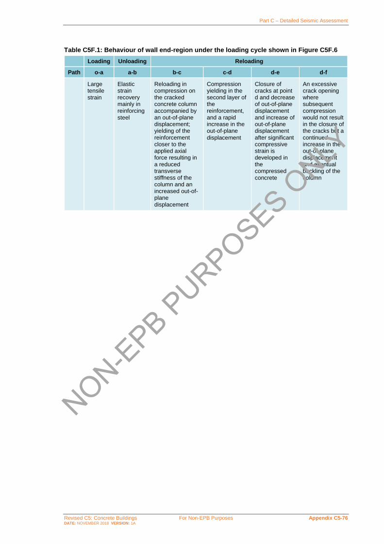
Part C – Detailed Seismic Assessment
Revised C5: Concrete Buildings For Non-EPB Purposes Appendix C5-76 DATE: NOVEMBER 2018 VERSION: 1A
Table C5F.1: Behaviour of wall end-region under the loading cycle shown in Figure C5F.6
Loading Unloading Reloading
Path o-a a-b b-c c-d d-e d-f
Large tensile strain
Elastic strain recovery mainly in reinforcing steel
Reloading in compression on the cracked concrete column accompanied by an out-of-plane displacement; yielding of the reinforcement closer to the applied axial force resulting in a reduced transverse stiffness of the column and an increased out-of-plane displacement
Compression yielding in the second layer of the reinforcement, and a rapid increase in the out-of-plane
displacement
Closure of cracks at point d and decrease of out-of-plane displacement and increase of out-of-plane displacement after significant compressive strain is developed in the compressed concrete
An excessive crack opening where subsequent compression would not result in the closure of the cracks but a continued increase in the out-of-plane displacement and eventual buckling of the column
NON-EPB P
URPOSES ONLY

Part C – Detailed Seismic Assessment
Revised C5: Concrete Buildings For Non-EPB Purposes Appendix C5-77 DATE: NOVEMBER 2018 VERSION: 1A
Procedure for Evaluating the Equivalent Flexural Capacity of Joints and Other Members
Procedure
In order to compare the hierarchy of strength and determine the expected sequence of events
within beam–column joint subassemblies the joint shear capacity can be expressed as a
function of a comparable parameter to the capacity of beams and columns. As a benchmark
parameter, it is suggested to take an equivalent moment in the column (based on equilibrium
considerations).
As a first step, the behaviour of beams and columns can be determined based on the
various failure mechanisms, including flexural, shear, lap-splice failure and bar buckling.
The (force-based) hierarchy of strength and expected sequence of events can be visualised
within an M-N interaction diagram or performance-domain (Pampanin et al., 2002) in order
to account for the variation of axial load during the frame sway mechanism.
As an example of the M-N interaction diagram for a column with poor detailing
Figure C5G.1 shows:
• conventional tensile and compressive flexural failures
• shear capacity/failure and shear degradation at various ductility levels (𝜇 = 2 and 𝜇 = 4)
• lap-splice failure of the column longitudinal reinforcement.
Figure C5G.1: Internal hierarchy of strength of column failure modes within an M-N interaction diagram (Kam, 2011)
Such force-based hierarchy of strength and sequence of event information should be
integrated with the information on the rotation or displacement capacities associated with
each mechanism.
Now considering the equivalent flexural capacity of beam-column joints, in Table C5G.1
and Figure C5G.2 below, the probable shear force 𝑉prob,jh is expressed as a function of the
moment in the column, leading to the expression of 𝑀col as the equivalent moment in the
column corresponding to the given joint parameter.
Column Hierarchy of
Strength (M-N Space)
0
5
10
15
20
25
30
35
40
45
50
55
60
0 40 80 120 160 200 240 280 320
Axial Load, N (kN)
Co
lum
n M
om
en
t, M
(kN
m)
Column M-N As-builtColumn M-N lap-splice (ASCE-41)Column M-N lap-splice (residual)Column Shear (duct<2)Column Shear (duct=4)Axial Load Demand
S-O1
Column Lap Splice
Lap-splice Residual
Lap-splice Residual
Column Lap Splice
NON-EPB P
URPOSES ONLY

Part C – Detailed Seismic Assessment
Revised C5: Concrete Buildings For Non-EPB Purposes Appendix C5-78 DATE: NOVEMBER 2018 VERSION: 1A
Table C5G.1: Step-by-step procedure to express the joint capacity as a function of equivalent column moment 𝑴𝐣 or 𝑴𝐜𝐨𝐥
Horizontal shear force acting on the joint core
𝑉jh = 𝑇 − 𝑉c …C5G.1
Equilibrium of the external action
𝑉c𝑙c = 𝑉b𝑙b …C5G.2
Rearrange to get 𝑉b 𝑉b =
𝑉c𝑙c
𝑙b …C5G.3
Moment acting at the face of the joint core 𝑀b = 𝑉b (𝑙b −
ℎc
2) = 𝑇𝑗𝑑 …C5G.4
Rearrange to get 𝑇
𝑇 =𝑀b
𝑗𝑑=
𝑉b(𝑙b−ℎc2
)
𝑗𝑑=
𝑉c𝑙c(𝑙b−ℎc2
)
𝑙b𝑗𝑑 …C5G.5
Substitute into the 1st equation 𝑉jh = 𝑇 − 𝑉c =
𝑉c𝑙c(𝑙b−ℎc2
)
𝑙b𝑗𝑑− 𝑉c = 𝑉c [
𝑙c
𝑙b𝑗𝑑(𝑙b −
ℎc
2) − 1] …C5G.6
Rearrange to get 𝑉c 𝑉c =
𝑉jh
[𝑙c
𝑙b𝑗𝑑(𝑙b−
ℎc2
)−1] …C5G.7
Joint capacity in terms of the column moment 𝑀col = 𝑉c (
𝑙c−ℎb
2) =
𝑉jh
[𝑙c
𝑙b𝑗𝑑(𝑙b−
ℎc2
)−1](
𝑙c−ℎb
2) …C5G.8
Assume 𝑗 = 0.9𝑑 and
𝐴e = 𝑏j × ℎc 𝑀col =𝜈jh(1000)
𝜙 kNm and 𝜙 =
2𝑙b′ 𝑙c−1.8𝑑𝑙b
0.9𝑑𝑙b𝐴e(𝑙c−ℎb) …C5G.9
Nominal horizontal shear stress at the mid-depth of the joint core
𝜈jh =𝑉jh
𝑏j×ℎc …C5G.10
Effective width of the joint 𝑏j = min(𝑏c, 𝑏w + 0.5ℎc) if 𝑏c ≥ 𝑏w …C5G.11
𝑏j = min(𝑏w, 𝑏c + 0.5ℎc) if 𝑏c ≤ 𝑏w …C5G.12
Principal tensile and compressive stresses 𝑝t = 𝑝c = −
𝑓v
2± 𝑅 …C5G.13
Substitute 𝑅 =
√(𝑓v
2)
2+ 𝜈jh
2 from Mohr’s
Circle Theory
𝑝t = −𝑓v
2+ √(
𝑓v
2)
2
+ 𝜈jh2 …C5G.14
Rearrange to get horizontal shear 𝜈jh = √𝑝t
2 + 𝑝t𝑓v …C5G.15
Substitute into the joint capacity equation 𝑀col =
√𝑝t2+𝑝t𝑓v(1000)
𝜙 kNm …C5G.16
Principal tensile stress 𝑝t = 𝑘√𝑓 c
′ …C5G.17
Stress due to axial load 𝑓v =
𝑁v
𝐴e …C5G.18
NON-EPB P
URPOSES ONLY

Part C – Detailed Seismic Assessment
Revised C5: Concrete Buildings For Non-EPB Purposes Appendix C5-79 DATE: NOVEMBER 2018 VERSION: 1A
(a) (b) (c)
Figure C5G.2: (a) Free-body diagram of a beam-column joint sub-assembly; (b) Mohr’s circle theory applied to calculate joint shear and principal tensile/compression stresses;
(c) Moment, shear and stresses at joint region (modified after Pampanin et al., 2003; Akguzel and Pampanin, 2010; Tasligedik et al., 2015)
For an interior joint the same procedure can be followed by:
• introducing the contribution from the compression steel, 𝐶′𝑠, of the other beam in the
first equation in Table C5G.1:
𝑉jh = 𝑇 + 𝐶′𝑠 − 𝑉c …C5G.19
assuming 𝑀b = 𝑀col for interior beam-column joints, instead of 𝑀b = 2𝑀col for
exterior joints, and
• checking that 𝑙b’ and 𝑙b are to be taken as the beam clear span and full span respectively,
consistent with an interior beam-column joint.
Figure C5G.3 illustrates an example M-N performance domain used to predict the sequence
of events and the level of damage in the joint panel zone of a 2D exterior beam-column joint
sub-assembly. This procedure requires the capacities of beams, columns, and joints to be
evaluated in terms of a common parameter. It is recommended that the equivalent moment
in the column is used, based on equilibrium during the selected limit state (e.g.
cracking/“yielding” or peak capacity in the joint versus yielding of beams and columns).
NON-EPB P
URPOSES ONLY

Part C – Detailed Seismic Assessment
Revised C5: Concrete Buildings For Non-EPB Purposes Appendix C5-80 DATE: NOVEMBER 2018 VERSION: 1A
Figure C5G.3: Example of evaluation of hierarchy of strengths and sequence of events: moment-axial load, M-N, performance domain for an exterior beam-column joint in as-built
configuration, (after Pampanin et al., 2007)
The capacity of a beam-column joint, particularly one with poor detailing and little or no
transverse reinforcement like those typically found in older buildings, is strongly affected
by the variation of the axial load. This was anticipated above by using principal stresses
instead of a nominal shear stress to provide a more realistic damage indicator. Therefore,
demand curves for beam-column joint systems should also account for the variation of axial
load due to the lateral sway mechanism, for both opening and closing of the joint (refer to
Figure C5G.4). Not doing this could provide a non-conservative assessment of the sequence
of events, which would lead to an inadequate – and not necessarily conservative – design of
any retrofit intervention.
Specimen T1 (as-built)
Type of
lateral force N° Event
Lateral force
[kN]
1 Joint cracking and deterioration
starting '19.0ct
fp -10.94
2 Beam yielding -16.59
3 Upper column yielding -20.50
Open joint
F<0
4 Lower column yielding -22.75
5 Joint failure 9.37
6 Lower column yielding 13.50
7 Upper column yielding 14.50
Close joint
F>0
8 Beam yielding 16.59
NON-EPB P
URPOSES ONLY

Part C – Detailed Seismic Assessment
Revised C5: Concrete Buildings For Non-EPB Purposes Appendix C5-81 DATE: NOVEMBER 2018 VERSION: 1A
Note:
In the case of the example exterior joint shown in Figure C5G.2, a shear hinge mechanism
is expected develop with extensive damage of the joint before any beam or column hinging
is expected, using a proper demand curve (refer to the table in Figure C5G.3). This is
confirmed by experimental tests.
However, as anticipated, the order and “distance” of the events strongly depend on the
assumption on the axial load demand curve.
If a constant axial load curve is used (in this example 𝑁𝑉 = -100 kN as shown in
Figure C5G.3), as this is often used in experimental tests and analytical assessments.
Only a relatively small increase in joint strength appears needed for a retrofit intervention.
However, such strengthening would lead to formation of a column hinge before any beam
hinging. This could result in development of a soft-storey mechanism even after the
(generally quite expensive and invasive) retrofit intervention.
(a) Laterally loaded frame (b) Hierarchy of strength and sequence of events for two types of exterior joints
Figure C5G.4: Variation of axial load due to frame sway mechanism and its effects on the hierarchy of strength of beam-column joint subassemblies
Note:
Most experimental cyclic tests on joint subassemblies (as well as column-to-foundation
connections) are carried out, for simplicity, under a constant axial force demand in the
column/joint.
While this simplified testing procedure is not expected to have a substantial effect on the
behaviour of well-designed specimens, in the case of poorly detailed subassemblies the
effect on damage level and mechanisms could be significant.
NON-EPB P
URPOSES ONLY

Part C – Detailed Seismic Assessment
Revised C5: Concrete Buildings For Non-EPB Purposes Appendix C5-82 DATE: NOVEMBER 2018 VERSION: 1A
In general, the axial force demand on a column can be expressed as:
𝑁𝑉 = 𝑁g ± 𝛼 𝐹 …C5G.20
where:
𝑁g = the axial force demand due to gravity (i.e. 𝐺 +Ψ𝐸𝑄)
𝐹 = the lateral force demand (base shear capacity), and
𝛼 depends on the global geometry of the building (height, H, and total
bay length, 𝐿, as shown in Figure C5G.5).
Such variation of axial force demand due to the seismic action can be substantial for
exterior beam-column joints. It can be 30-50% or higher, with a further increase when
considering bidirectional loading.
On the other hand, as a first approximation (especially if there are only two or three bays)
the variation of axial force demand in interior beam-column joints can either be neglected
or assumed to be in the order of 10-20%.
𝐹 (2
3𝐻) = 𝑅𝐿 ⇒ 𝑅 =
2
3
𝐻
𝐿𝐹 ∴ 𝑁 = 𝑁g ±
2
3
𝐻
𝐿⏟𝐹
𝛼
Figure C5G.5: Example of evaluation of variation of axial force demand in a frame
NON-EPB P
URPOSES ONLY


