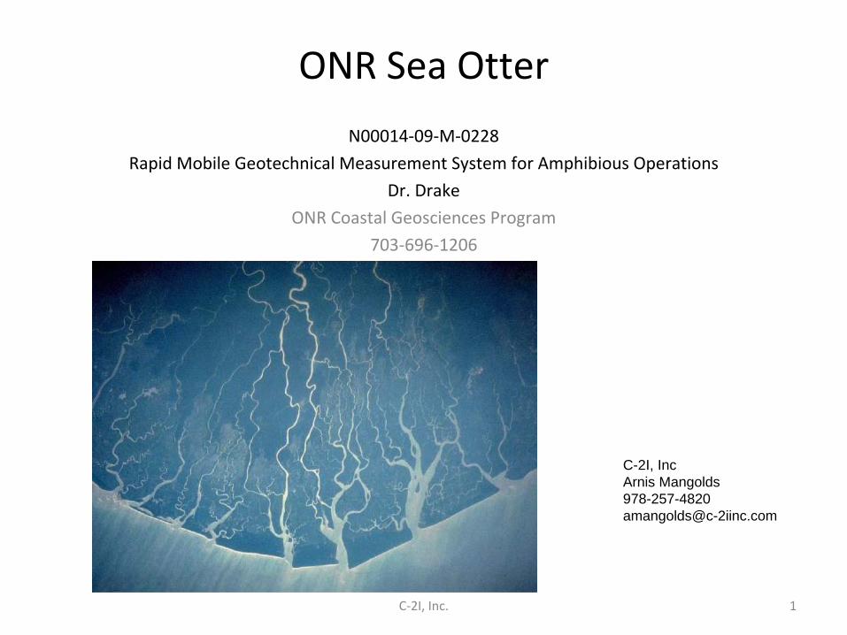
ONR Sea Otter N00014‐09‐M‐0228 Rapid Mobile Geotechnical Measurement System for Amphibious Operations Dr. Drake ONR Coastal Geosciences Program 703‐696‐1206 1 C‐2I, Inc. C-2I, Inc Arnis Mangolds 978-257-4820 [email protected]
Transcript
ONR Sea Otter
N00014‐09‐M‐0228
Rapid Mobile Geotechnical Measurement System for Amphibious Operations
• Alternatives:– Single point probes only good for uniform beaches,
susceptible to drop error– Drifters are unpredictable – Hyperspectral
cannot penetrate murky or turbulent water
– SEAL teams are exposed and require considerable
logistical support
• Bottom crawlers can cover large areas, obtain continuous data.
C‐2I, Inc. 2
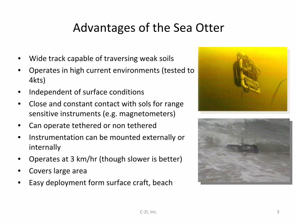
Advantages of the Sea Otter
• Wide track capable of traversing weak soils
• Operates in high current environments (tested to
4kts)
• Independent of surface conditions
• Close and constant contact with sols for range
sensitive instruments (e.g. magnetometers)
• Can operate tethered or non tethered
• Instrumentation can be mounted externally or
internally
• Operates at 3 km/hr (though slower is better)
• Covers large area
• Easy deployment form surface craft, beach
C‐2I, Inc. 3
Sea Otter Output Data
• Penetration resistance • scaled CBR, CI, RCI relates to NATO trafficability model• Continuous measurement to 18‐in depth
• Continuous measurement identifies channels, bars, other invisible features
• Shear strength, draw bar pull or tractive effort• Ground slope (contour)• Surface ground roughness• Water depth • Current speed and direction
• Simple to include visual reconnaissance, turbidity, comms surveys
4C‐2I, Inc.
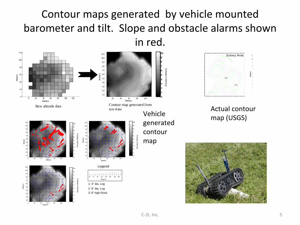
Contour maps generated by vehicle mounted barometer and tilt. Slope and obstacle alarms shown
in red.
C‐2I, Inc. 5
20 40 60 80 100
10
20
30
40
50
60
70
80
90
100
110
0
1
2
3
4
5
6
7
8
9
10
Raw altitude data Contour map generated from
raw data
0
1
2
3
4
5
6
7
8
9
10
Meters M
eter
s Meters
Met
ers
Elev
atio
n (M
eter
s)
1
2
3
4
5
6
7
8
9
10
11
Survey Area
110’
100’
Met
ers
0 20 40 60 80 100
10
20
30
40
50
60
70
80
90
100
110
0 20 40 60 80 100
10
20
30
40
50
60
70
80
90
100
110
0 20 40 60 80 100
10
20
30
40
50
60
70
80
90
100
110
0 4 8 12 16 20 24 28
Legend
2: 8” dia. Log 1: 3” dia. Log
3: 6” high Rock
1 2
3
2
3
2
3
Degrees
0
1
2
3
4
5
6
7
8
9
10
Meters
Met
ers
0
1
2
3
4
5
6
7
8
9
10
Meters
Met
ers
0
1
2
3
4
5
6
7
8
9
10
Meters
Met
ers
Elev
atio
n (M
eter
s)
Elev
atio
n (M
eter
s)
Elev
atio
n (M
eter
s)
Actual contour
map (USGS)Vehicle
generated
contour
map
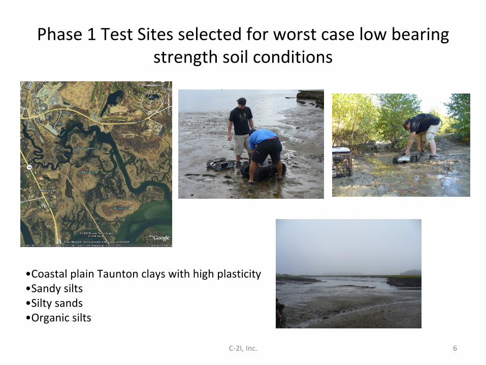
Phase 1 Test Sites selected for worst case low bearing strength soil conditions
•Coastal plain Taunton clays with high plasticity •Sandy silts•Silty sands•Organic silts
6C‐2I, Inc.
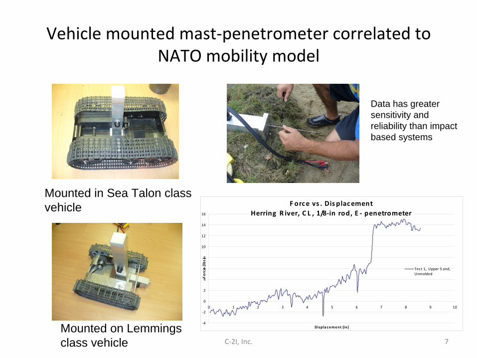
Vehicle mounted mast‐penetrometer correlated to NATO mobility model
F orce vs . Dis placementHerring R iver, C L , 1/8‐in rod, E ‐ penetrometer
‐4
‐2
0
2
4
6
8
10
12
14
16
0 1 2 3 4 5 6 7 8 9 10
Displacement (in)
Force (lbs)
Tes t 1, Upper S and,Unmolded
7C‐2I, Inc.
Mounted in Sea Talon class vehicle
Mounted on Lemmings class vehicle
Data has greater sensitivity and reliability than impact based systems
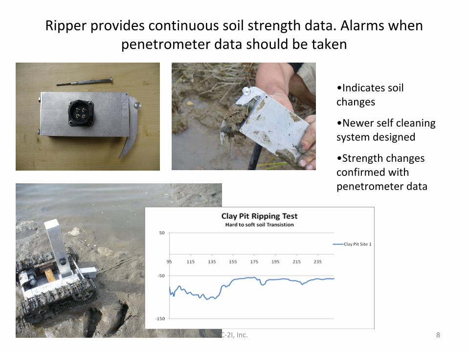
Ripper provides continuous soil strength data. Alarms when
penetrometer data should be taken
•Indicates soil
changes
•Newer self cleaning
system designed
•Strength changes
confirmed with
penetrometer data
8C‐2I, Inc.
Testing performed on various vehicle chassis and correlated to standard soil mechanic instrumentation
•Tested in weak saturated
marine sediments
•Compared to proving ring and
hydraulic manual penetrometers
9C‐2I, Inc.
Lemmings vehicle in background, Sea Talon in foreground
10C‐2I, Inc.
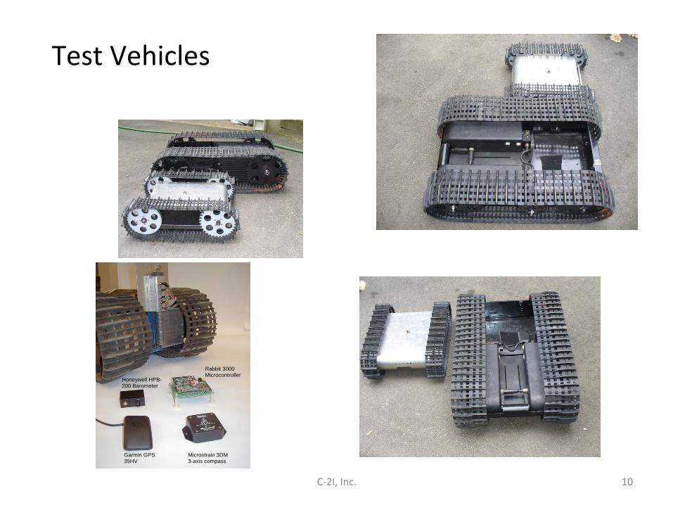
Rabbit 3000 Microcontroller
Garmin GPS 35HV
Microstrain 3DM 3-axis compass
Honeywell HPB-200 Barometer
Test Vehicles
C‐2I, Inc. 11
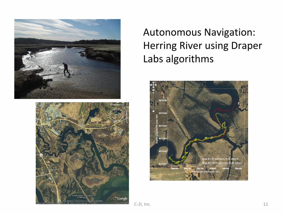
Autonomous Navigation: Herring River using Draper
Labs algorithms
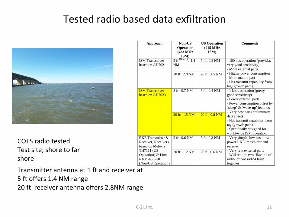
Tested radio based data exfiltration
Transmitter antenna at 1 ft and receiver at 5 ft offers 1.4 NM range 20 ft receiver antenna offers 2.8NM range
Approach Non-US Operation (433 MHz
ISM)
US Operation (915 MHz
ISM)
Comments
ISM Transceiver based on AD7021
5 ft [Note 1]: 1.4 NM
5 ft: 0.8 NM - 100 bps operation (provides very good sensitivity) - More external parts - Higher power consumption - More mature part - Has transmit capability from tag (growth path)
20 ft: 2.8 NM 20 ft: 1.5 NM
ISM Transceiver based on AD7023
5 ft: 0.7 NM 5 ft: 0.4 NM - 1 kbps operation (pretty good sensitivity) - Fewer external parts - Power consumption offset by ‘sleep’ & ‘wake-up’ features - Very new part (preliminary data sheets) - Has transmit capability from tag (growth path) - Specifically designed for world-wide ISM operation
20 ft: 1.5 NM 20 ft: 0.8 NM
RKE Transmitter & Receiver, Receivers based on Melexis TH7111 (US Operation) & Linx RXM-433-LR (Non-US Operation)
5 ft: 0.6 NM 5 ft: 0.3 NM - Very simple, low cost, low power RKE transmitter and receiver - Very few external parts - Will require two ‘flavors’ of radio, or two radios built together
20 ft: 1.2 NM 20 ft: 0.6 NM
COTS radio tested Test site; shore to far
shore
12C‐2I, Inc.
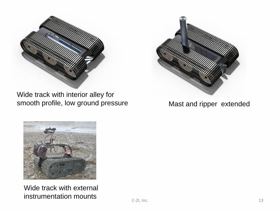
C‐2I, Inc. 13
Wide track with interior alley for smooth profile, low ground pressure Mast and ripper extended