Onsite Treatment of Tank Water'Bottoms with SDI's Hybrid Membrane Separation System Billy Scherer Ph.D., Roy Larson SDI Environmental Contract Services a division of Separation Dynamics International, Ltd. Houston, Texas USA SUMMARY Presented in this paper is a description of a new membrane separation technology that is being used in Mobile Treatment Systems for the treatment of tank water bottoms. This new membrane separation process, SDI's Hybrid Membrane Separation System, uses SDI's EXTRAN, membrane in combination with nanofiltration, and secondary treatment processes like carbon adsorption to treat wastewater with highly soluble organic compounds and hydrocarbons. EXTRANTM membranes are composed of cellulose made by a proprietary SDI process into hollow fibers (inner diameter of 400 microns), which are potted into suitable pressure vessels (modules) and incorporated into a system. EXTRAN, membrane is resistant to a vast array of hydrocarbons and organic solvents. Being a true water diffusion membrane, it has no pores to clog. These properties in combination with high tangential velocity through the bore of the fiber allows continuous operation with no online chemical cleaning. Periodic use of a biocide to kill any bacteria growing inside the EXTRAN, membrane module is practiced. SDI Environmental Contract Services utilizes this new Hybrid Membrane Separation System on a mobile basis to separate and recover hydrocarbons from wastewater and send these products back to the customer's wastewater storage tank for reuse. Hydrocarbons that pass through the EXTRAN, membrane and the nanofiltration system are removed by secondary treatment processes such as carbon adsorption to levels that are in compliance with the customer's discharge permit. This paper presents data gathered during the successful treatment of 600,000 gallons of tank water bottoms containing highly soluble end products of anaerobic bacterial degradation. In this case, the combination of EXTRAN,, membrane separation and nanofiltration removed 59% of the BTEX, 88% of the MTBE and 71% of the Oil and Grease. For tank water that has not undergone severe biodegradation, EXTRANT, membranes alone separate approximately 70% to 90% of BTEX. In this case, only 36% of the BTEX was removed by EXTRANTH membranes, since this membrane's separation efficiency is a function of the solubility of the target organic compounds in water. Environmental Contract Services' Mobile Treatment Systems offer the industry a cost effective means of disposing of tank water bottoms, which eliminates offsite transportation and disposal of a hazardous waste. Onsite treatment by SDI allows the terminal operator to concentrate on moving products instead of treating waste.
Transcript
Onsite Treatment of Tank Water'Bottoms with
SDI's Hybrid Membrane Separation System
Billy Scherer Ph.D., Roy Larson SDI Environmental Contract Services
a division of Separation Dynamics International, Ltd.
Houston, Texas USA
SUMMARY
Presented in this paper is a description of a new membrane separation technology that is being used in Mobile Treatment Systems for the treatment of tank water bottoms. This new membrane separation process, SDI's Hybrid Membrane Separation System, uses SDI's EXTRAN, membrane in combination with nanofiltration, and secondary treatment processes like carbon adsorption to treat wastewater with highly soluble organic compounds and hydrocarbons. EXTRANTM membranes are composed of cellulose made by a proprietary SDI process into hollow fibers (inner diameter of 400 microns), which are potted into suitable pressure vessels (modules) and incorporated into a system. EXTRAN, membrane is resistant to a vast array of hydrocarbons and organic solvents. Being a true water diffusion membrane, it has no pores to clog. These properties in combination with high tangential velocity through the bore of the fiber allows continuous operation with no online chemical cleaning. Periodic use of a biocide to kill any bacteria growing inside the EXTRAN, membrane module is practiced.
SDI Environmental Contract Services utilizes this new Hybrid Membrane Separation System on a mobile basis to separate and recover hydrocarbons from wastewater and send these products back to the customer's wastewater storage tank for reuse. Hydrocarbons that pass through the EXTRAN, membrane and the nanofiltration system are removed by secondary treatment processes such as carbon adsorption to levels that are in compliance with the customer's discharge permit. This paper presents data gathered during the successful treatment of 600,000 gallons of tank water bottoms containing highly soluble end products of anaerobic bacterial degradation. In this case, the combination of EXTRAN,, membrane separation and nanofiltration removed 59% of the BTEX, 88% of the MTBE and 71% of the Oil and Grease. For tank water that has not undergone severe biodegradation, EXTRANT, membranes alone separate approximately 7 0 % to 90% of BTEX. In this case, only 3 6 % of the BTEX was removed by EXTRANTH membranes, since this membrane's separation efficiency is a function of the solubility of the target organic compounds in water.
Environmental Contract Services' Mobile Treatment Systems offer the industry a cost effective means of disposing of tank water bottoms, which eliminates offsite transportation and disposal of a hazardous waste. Onsite treatment by SDI allows the terminal operator to concentrate on moving products instead of treating waste.
'9
3
Initial Investigation
Prior to initiating work at this wholesale bulk petroleum products terminal (A), 61,000 gallons of tank water were treated at another of the customer's terminals (B) using EXTRAN, membrane separation followed by carbon adsorption. The first 41,000 gallons met the permit limits and was discharged from rented temporary tanks. The final 20,000 gallons had non-detectable concentrations of Benzene, Toluene, Ethyl-benzene, and toluene (BTEX) at less than 1 ppb and non-detectable Oil and Grease (<1 ppm) with a Total Organic Carbon (TOC) of 231 ppm. Since the permit limit for TOC was 55 ppm, the water could not be discharged from the temporary storage tanks.
Assuming that the carbon had been saturated by TOC, virgin carbon (coconut based carbon) was placed in two columns. This treated water with no detectable hydrocarbons and 231 ppm of TOC was run through the two columns arranged in series. This resulted in a feed concentration of 290 ppm being reduced to 280 ppm.
The water at terminal A was treated with EXTRAN, membrane separation followed by carbon adsorption also. Two carbon columns were used in series, one with coconut based carbon and the other with charcoal based carbon. This resulted in non-detectable concentrations of BTEX and Oil and Grease, with a TOC of 330 ppm. This water, which had no detectable hydrocarbons was run on a mass spectrophotometerto determine the source of the remaining TOC. The baseline for the chromatograph was virtually flat. Since mass spectrophotometry subjects the sample to 45 minutes of heat and distillation, it is reasonable to assume that air stripping this waste would not lower the effluent TOC to less than 55 ppm.
Analytical Investigation of the TOC Source
Since there was no untreated tank water at terminal B, mass spectrophotometry was used to identify specific compounds in the tank water at terminal A. Since these two tank waters had been subjected to the same conditions, it was assumed they were very similar in characteristics. MTBE (320 ppm) , BTEX (67 ppm) , and other hydrocarbons (7 ppm) were the only petroleum compounds found.
Analysis for surfactant determined that only 1.7 ppm was present in the water at terminal A. The terminal manager at terminal B stated that their driveway through the loading rack is only washed once a quarter: so, surfactant was ruled out as a TOC source.
Corrosion inhibitors used in the pipeline were found to be an insoluble aromatic compound: therefore corrosion inhibitors were ruled out.
The conclusion was drawn, that anaerobic bacteria had degraded the hydrocarbons and other organic compounds in the tank water. The end products of this degradation are organic acids and severely hydrolyzed organic compounds which are extremely water soluble. The
4
initial pH of the water was 5.3, which meant that the methane forming bacteria populations were not present in great numbers. This prevented the majority of organic acids from being converted to methane.
P i l o t T e s t i n g
A literature search was conducted to determine the most feasible approaches to removing the remaining TOC. Nanofiltration and biological treatment were the two methods that were available and had a good chance for success. Since SDI's president, Roy Larson, was president of FilmTec, a Dow company, when FilmTec's NF 7 0 nanofiltration modules were developed, we decided to pursue this avenue. An additional factor was the anticipated difficulty in operating and controlling a biological treatment system on a mobile basis ,
A two module nanofiltration pilot system was taken to terminal B in an effort to treat the remaining 20,000 gallons being held. This wastewater had been sitting in an open top temporary tank for a month during the summer.
Over a four day period, just under 18,000 gallons were treated using EXTRAN,, membrane separation, nanofiltration, and carbon adsorption in that order, The following data documented permit limit compliance, allowing discharge of the water:
This pilot unit was then taken to terminal A, where it operated continuously for two weeks in an effort to verify sustainable flow given the high levels of hydrocarbons and iron (60 ppm) in the feed stream. FilmTec recommends not exposing their NF 70 modules to more than 1 ppm of hydrocarbons or iron.
The flow rate stabilized at 4 gallons per minute (gpm) at a feed pressure of 100 psi and a temperature of 25 C.
..>
Commercial System Design: Treatment Scheme '
The treatment scheme used at the terminal A is shown below:
I I --Temporary Storage e---- Carbon Adsorption <-----------------
Tanks
----------------------> Discharge Via NPDES Permit
The feed from the storage tanks was pumped to the Mobile Treatment System trailer which houses the EXTRAN, membrane separation system and two activated carbon beds in series, This trailer is built to explosion proof standards internally with an air cooling system for operation in the hot Texas summers. The trailer has an electric generator; therefore, the entire system is self sufficient.
All components of the trailer will automatically shut down in the event that the gas monitoring system in the trailer detects over 5% of the lower explosive limit of petroleum vapors in air.
Commercial System Design: EXTRAN Membrane Separation System
EXTRAN, membranes are composed of cellulose made by a proprietary SDI process into hollow fibers (inner diameter of 400 microns), which are potted into suitable pressure vessels (modules) and incorporated into a system. EXTRAN, membrane is resistant to a vast array of hydrocarbons and organic solvents. Being a true water diffusion membrane, it has no pores to clog. These properties in combination with high tangential velocity through the bore of the hollow fiber allows continuous operation with no online chemical cleaning.
EXTRAN,, membranes are absolutely critical and vital in protecting the nanofiltration system from fouling. The clear yellow permeate produced during this project contained no suspended solids, no insoluble oils and greases, and reduced concentrations of dissolved hydrocarbons. This membrane provides as much protection as possible, without fouling, for nanofiltration.
The EXTRAN, membrane separation system has a treatment capacity of 70 gallons per minute. It is automated to shut down in the event that proper operating conditions are not adhered to.
.
3
‘I
.>
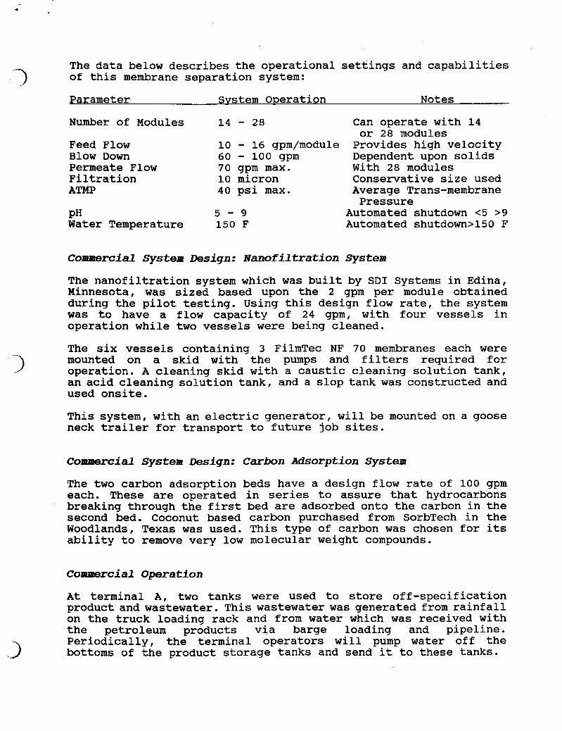
The data below describes the operational settings and capabilities of this membrane separation system:
Provides high velocity Dependent upon solids With 28 modules Conservative size used Average Trans-membrane
Automated shutdown <5 >9 Automated shutdown>l50 F
or 28 modules
Pressure
Commercial System Design: Nmofiltration System
The nanofiltration system which was built by SDI Systems in Edina, Minnesota, was sized based upon the 2 gpm per module obtained during the pilot testing. Using this design flow rate, the system was to have a flow capacity of 24 gpm, with four vessels in operation while two vessels were being cleaned.
The six vessels containing 3 FilmTec NF 70 membranes each were mounted on a skid with the pumps and filters required for operation. A cleaning skid with a caustic cleaning solution tank, an acid cleaning solution tank, and a slop tank was constructed and used onsite.
This system, with an electric generator, will be mounted on a goose neck trailer for transport to future job sites.
Commercial system Design: Carbon Adsorption system
The two carbon adsorption beds have a design flow rate of 100 gpm each. These are operated in series to assure that hydrocarbons breaking through the first bed are adsorbed onto the carbon in the second bed. Coconut based carbon purchased from SorbTech in the Woodlands, Texas was used. This type of carbon was chosen for its ability to remove very low molecular weight compounds.
Commercial Operation
At terminal A, two tanks were used to store off-specification product and wastewater. This wastewater was generated from rainfall on the truck loading rack and from water which was received with the petroleum products via barge loading and pipeline. Periodically, the terminal operators will pump water off the bottoms of the product storage tanks and send it to these tanks.
'3
3
Prior to treatment, this tank water 'had the following characteristics:
Parameter Concentration Permit Limit Unit
BTEX 45 Oil and Grease 148 Total Organic Carbon 953 PH 5.3
1 15 55
6 - 9
PPM PPM PPM
Commercial Operation: SDI Hybrid Membrane Separation System
On November 21, 1991, the system started to treat tank water at terminal A. As of January 27, 1992 this Hybrid Membrane Separation System has treated just under 600,000 gallons of tank water.
Commercial Operation: Flow Data
EXTRAN, Membrane SeDaration
As Figure A shows, the EXTRAN, membrane separation system permeate flow varied between a daily average of 28 gpm and 36 gpm for 14 modules in operation. These flow rates have been normalized to a constant temperature of 25 C and 30 psi ATMP, Average Trans- membrane Pressure. ATMP is calculated by averaging the pressures that exist at the entrance and exit points of the modules minus the permeate pressure.
These membranes were not chemically cleaned during any of the Operating time from November 21, 1991 to January 27, 1992, even though high levels of hydrocarbons existed in the feed.
To prepare the membranes for storage during the Thanksgiving (Day 4 to 8) and Christmas (Day 26 to 42) Holidays, the membranes were washed with soapy water for 15 minutes. This was accomplished by circulating and permeatingthe soapy water through the system. This was followed by a clean water rinse. The last step was filling the system with a biocide in water mixture, which also contained glycerine to prevent freezing.
The same fourteen EXTRAN,, membranes that were loaded into the system at the start of the job, were used until Day 43. Although the membranes survived the Thanksgiving Holiday, they began to have cloudy permeate on Day 43, roughly 24 hours after startup following the Christmas Holiday. The entire set of 14 were removed to assure that poor quality permeate did not reach the nanofiltration system.
Autopsy of the modules determined that bacteria had weakened the fibers; causing rupture of the fibers. We are now incorporating periodic washing of the EXTRAN,, membranes with a biocide to kill any bacteria present in the module. It is emphasized that this is not done for the purpose of maintaining flow, but for the purpose
.
Figure A: Extran Permeate Flow Flow Adjusted to 25 C and 30 PSI ATMP
Permeate Flow System shut down from Day 4 to 8 and Day 26 to 42.
of assuring that the modules are not attacked by bacteria.
.>
Nanofiltration Svstem
As shown on Figure B, the nanofiltration system began the job with a flow rate of 27 gpm, normalized to 25 C and 90 psi. This rapidly fell to a daily average of 22 gpm within one day. The flow rate continuedto decrease until the Thanksgiving Holiday, six days into the job. The membranes were left to soak in a caustic cleaner over the four day holiday.
On start up after the holiday, the flow increased to 18 gpm; however, this flow rate decreased to 14 gpm within 12 hours. The flow rate continued to decline until 10 gpm was reached on Day 17 of the job. Since the flow rate on a per module basis had declined to 0 . 8 gpm instead of the 2 gpm obtained during pilottesting, all six vessels were operated simultaneously from Day 22 through Day 2 8 . The flow rate increased by only 10% to an average of 11 gpm initially, but decreased to a daily average of 10 gpm by Day 28.
During the Christmas Holiday (Day 28 through Day 42), a caustic cleaner was circulated every other day for 3 hours and left to soak the membranes between cleaning. On start up only four vessels were used to obtain daily average flow rates of 10 to 11 gpm.
On Day 46, all six vessels were once again used. The daily average flow rate increased to 12 gpm.
From Day 48 to Day 51, rigorous cleaning with caustic and acid cleaners was accomplished. Care was taken to replace the cleaning solutions when it began to look like coffee. This cleaning increased the flow to 14 gpm with only four vessels operating on Day 52. Once again, all of these flow rates are normalized to 25 C and 90 psi.
After the flow stabilized at 10 to 11 gpm, cleaning cycles were 24 hours apart, a time period that correlates to a 10% decline in flow from the flow rate achieved 30 minutes after the previous cleaning. Often times though the decline would be less than 10%: however, as a matter of good practice the membranes were cleaned at this frequency anyway.
Since the Figures were prepared for this paper, the flow rate has stabilized once again at 10 gpm for four vessels, normalized to 25 C and 90 psi. SDI will increase the flow capacity of the nanofiltration system to 40 gpm after this project, using the stable flow rate of 0.8 gpm per module.
30
25
5; z 2o a C ecI
VI (u
U 15
@, 2 10 s
5
0
Figure 6: NF Permeate Flow Normalized to 25 C and 90 PSI
Flow (GPM) All 6 vessels online from 22 to 43 days and 46 to 52 days System shut down from 6 to 11,28 to 42, and 48 to 51
Commercial Operation: Hydrocarbon Removal and' Effluent Quality Data '7
3
BTEX Figure C shows the Feed and Final Effluent BTEX values documented by PSI Professional Service Industries in Pasadena, Texas. During the commercial operation of this system from November 21, 1991 to January 12, 1992, non-detectable concentrations of less than 1 ppb were verified on every sample except one, which had a BTEX value of 1 ppb. The permit limit for BTEX is 1 ppm or 1000 ppb. Feed concentrations ranged between 67 ppm and 79 ppm during the entire project.
Oil and Grease
In Figure D, Oil and Grease concentration of the Feed, 41 ppm, is shown for the only feed sample taken during commercial operation. This value illustrates the soluble nature of the contaminants, since the BTEX value obtained for this sample was 79 ppm. Oil and Grease values should include BTEX. Evidently the EPA extraction method used to extract the hydrocarbons from the sample during sample preparation could not extract all of these very water soluble compounds.
Final Effluent values were non-detectable at less than 1 ppm for all the samples except two, which had concentrations of 2 ppm, a value well below the 15 ppm permit limit.
TOC
TOC values in the feed varied from 672 to 1500 ppm, as shown on Figure E. These values increased as the membrane separation systems concentrated the organic compounds in the customer's feed tank. Effluent values ranged between 16 and 37 up to January 6, 1992. The discharge limit is 55 ppm.
After measuring 101 ppm in the effluent, the water was treated with carbon adsorption only which reduced the concentration to 61 ppm. The carbon in both tanks was removed and replaced with virgin carbon.
The water was once again treated by carbon adsorption only, which resulted in a concentration of 17 ppm. Since the graphs were prepared, TOC effluent concentrations were under the 55 ppm limit until January 23, 1992. On this day, the effluent had non- detectable concentrations of BTEX and Oil and Grease with a TOC of 110 ppm. The water was retreated twice by carbon adsorption with no change in the TOC concentration.
Pilot tests were conducted to determine the feasibility of oxidizing the remaining TOC with hydrogen peroxide. Analytical results showed no reduction in TOC by this method.
Figure C: Feed and Final Effluent BTEX Values SDI Hybrid Membrane System
0.06
0.05
E W 2 0.04 z 5 0.03 E 0
@ fl! 0.02 cd E iz
0.01
0
78.5 X
66.7 I
0.03
90
80
70
60 E a a
w 50 2 40 &
-8 30 E
20
10
0 10/15 22 24 11/21 24 12/3 8 12 16 18 7
21 23 30 23 26 6 10 15 17 1/6 12 MonthDay
Final Effluent Feed Permit Limit = 1 ppm. Detection Limit = 1 ppb. Non-detectable is shown as < 1 ppb. Pilot Study 10/15 to 10/30. Commercial Operation 11/21 to 1/12/92. Carbon change out on 1/8/92.
3
.>
200
150 h
E k s g 100 5
8
p1
a
50
0
Figure D: Feed and Final Effluent Oil & Grease Values SDI Hybrid Membrane System
Final Effluent Feed Permit Limit = 15 ppm. Detection Limit = 1 ppm. Non-detectable is shown as < 1 ppm. Pilot Study 10/15 to 10/30. Commercial Operation 11/21 to 1/12/92. Carbon change out on 1/8/92.
Final Effluent Feed Permit Limit = 55 ppm. Detection limit = 1 ppm. Pilot Study 10/15 to 10/30. Commercial Operation 11/21 to 1/12/92. Carbon change out 1/8/92.
DH The pH of the tank water was raised initially from 5.3 to 6.5 in the customer's tank by adding sodium hydroxide. The pH of the effluent was maintained between 6 and 9, the permit limits by adding soda ash to the water while in the temporary storage tanks, if necessary. The pH of the feed gradually lowered during the job, as the anaerobic bacteria created more organic acids.
C o e c i a l Operation: Analysis of System Component Performance
On December 18, 1991, samples were taken at each point in the system to determine the removal efficiency of each process used to treat the wastewater.
Figure F shows the removal of BTEX by each component. EXTRAN, membranes removed between 33% (benzene) and 39% (toluene). This removal rate is below the 70% to 90% removal efficiency documented for other hydrocarbon contaminated wastewaters. The nanofiltration system removed roughly 20% to 25% of these compounds, resulting in an accumulative removal for both membrane systems of 44% (Ethyl- benzene) to 63% (toluene).
Carbon adsorption produced a final effluent with non-detectable concentrations of benzene, toluene, ethyl-benzene, and xylene, an accumulative reduction for the Hybrid Membrane Separation System of 99.97% to 99.997%.
BTEX removal as a sum of the four compounds was 99.987% or non- detectable at less than 1 ppb, shown as Figure G.
Methyl-tertiary-butyl-ether removal rates were 29% for EXTRAN,, membranes and another 59% by nanofiltration for an accumulative removal rate of 88% (170 to 120 to 20 ppm). Carbon adsorption resulted in a non-detectable concentration at less than 1 ppb. See Figure G.
Oil and Grease
EXTRAN, membranes removed 71%, with nanofiltration removing the remaining Oil and Grease to a non-detectable concentration of less than 1 ppm. See Figure G.
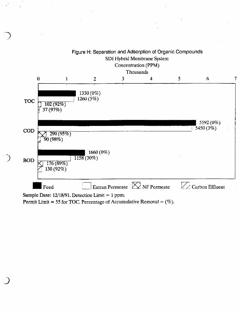
In Figure H, data shows that EXTRANTM membranes removed 5% while nanofiltration removed another 87%. After carbon adsorption, the effluent value was 37 which correlates to an accumulative removal rate of 97%.
Figure F: Separation and Adsorption of Hydrocarbons SDI Hybrid Membrane System
Concentration (PPM) 0 10 20 30 40 50
I I I I
24 (0%) Benzene
38 (0%) Toluene
E -Benzene
14 (0%) 1 Xylene %)
Feed El fitran Permeate NF Permeate G/d Carbon Effluent
Figure G: Separation and Adsorption of Hydrocarbons SDI Hybrid Membrane System
Concentration (PPM) 50 100 150 200
I
BTEX
170 (0%)
MTBE
41 (0%)
I Feed 0 fitran Permeate NF Permeate Carbon Effluent
Sample Date: 12/18/91. Detection Limit = 1 ppb for BTEX and MTBE. Detection Limit for 0 & G = 1 pi Permit Limit = 1 ppm BTEX. Percentage of Accumulative Removal = (%).
Figure H: Separation and Adsorption of Organic Compounds SDI Hybrid Membrane System
Concentration (PPM) Thousands
0 1 2 3 4 5 6 7
I 5592 (0%) 1 5450(3%)
1660 (0%) )
El Extra Permeate €32 NF Permeate E Carbon Effluent Sample Date: 12/18/91. Detection Limit = 1 ppm. Permit Limit = 55 for TOC. Percentage of Accumulative Removal = (%).
COD removal was almost identical to TOC at accumulative removal rates of 3%, 95%, and 98% for each stage in the process. See Figure H.
BOD. Removal rates for BOD, were similar to those of TOC and COD, except EXTRAN, membranes removed 30%, approximately six times the removal rates observed for COD and TOC. Since EXTRAN, membranes are non- porous, all suspended solids are removed. It appears that solids contributed significantly to the BOD. See Figure H.
ssolved Solids
In Figure I, data shows that 5% of the dissolved solids were removed by EXTRAN, membranes. These membranes remove contaminants based upon their solubility in water. Since dissolved solids are totally in solution, EXTRAN, membranes would theoretically not alter the dissolved solids concentration. This is demonstrated by the lack of removal of chlorides. The 5% difference could be the result of analytical variance.
Total Iron removal shown in Figure H, was 4% by EXTRAN,, membranes and 99% removal by nanofiltration, which is also the removal rate demonstrated for dissolved iron.
Conclusions
This project resulted in a new treatment system, SDI Hybrid Membrane Separation System, being developed, pilot tested, constructed and successfully operated on a commercial basis in a period of three months.
The stable flow rate demonstrated by the nanofiltration system (0.8 per module) can be used to design and build large scale nanofiltration systems to use in series with SDI's own EXTRAN,, membrane separation system.
EXTRAN, membranes are absolutely critical and vital in protecting the nanofiltration system from fouling. The clear permeate which contains no suspended solids, no insoluble oils and greases, and reduced concentrations of dissolved hydrocarbons provides an excellent feed for nanofiltration.
SDI Hybrid Membrane Separation System can meet discharge permit limits for tank water bottoms.
The onsite treatment of tank water bottoms and other hydrocarbon contaminated wastewaters by SDI's Mobile Treatment System eliminates the offsite transportation and disposal of a hazardous waste. This delivers cost savings to the petroleum industry.
Figure I: Separation of Dissolved Solids SDI Hybrid Membrane System