Op Amp Applications. Analyses for A ∞ and loop gain are separate. Design breaks down into two parts: Arranging A ∞ to do the job Ensuring the feedback loop has enough loop gain and is stable. Here we focus on the A ∞ part, assuming you already know how to get a stable feedback loop. - PowerPoint PPT Presentation
Op Amp Applications 1 EEE 3308 Analyses for A ∞ and loop gain are separate. Design breaks down into two parts: - Arranging A ∞ to do the job - Ensuring the feedback loop has enough loop gain and is stable. Here we focus on the A ∞ part, assuming you already know how to get a stable feedback loop.
Transcript
Op Amp Applications
1EEE 3308
Analyses for A∞ and loop gain are separate.
Design breaks down into two parts:
- Arranging A∞ to do the job- Ensuring the feedback loop has enough loop gain and is stable.
Here we focus on the A∞ part, assuming youalready know how to get a stable feedback loop.
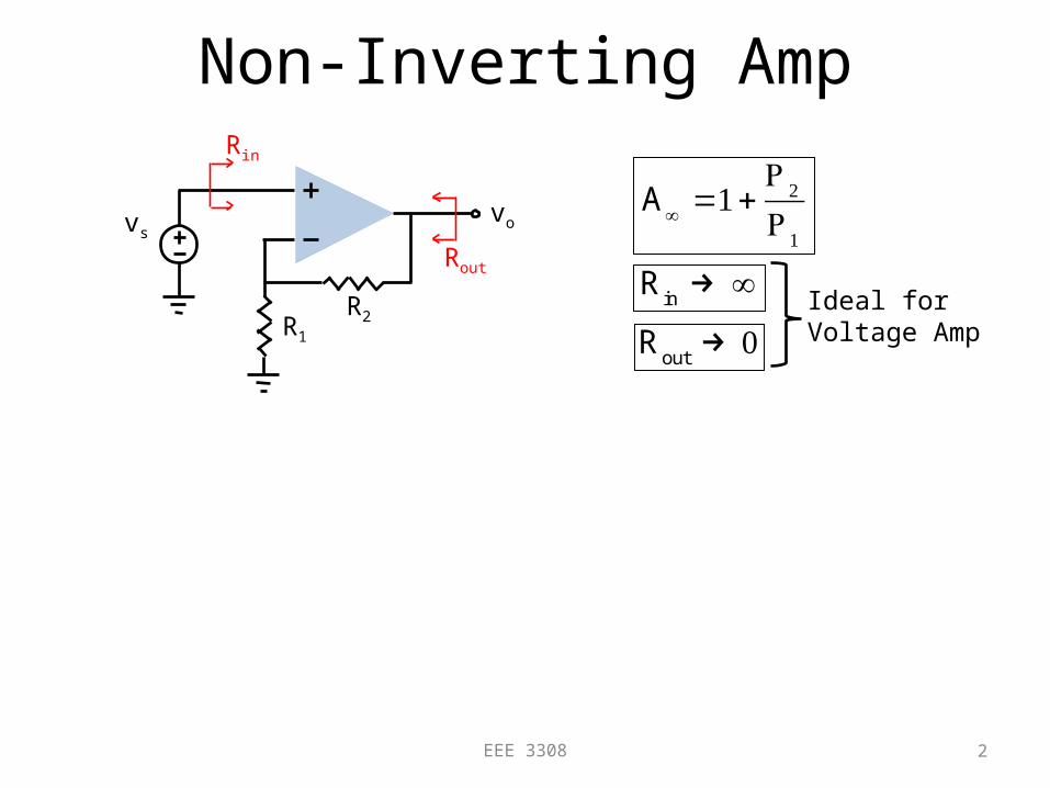
Non-Inverting Amp
2EEE 3308
R2R1
vsvo
Rout
Rin
Rin→ ∞
Rout→ 0
Ideal forVoltage Amp
A∞ =1+
R2
R1
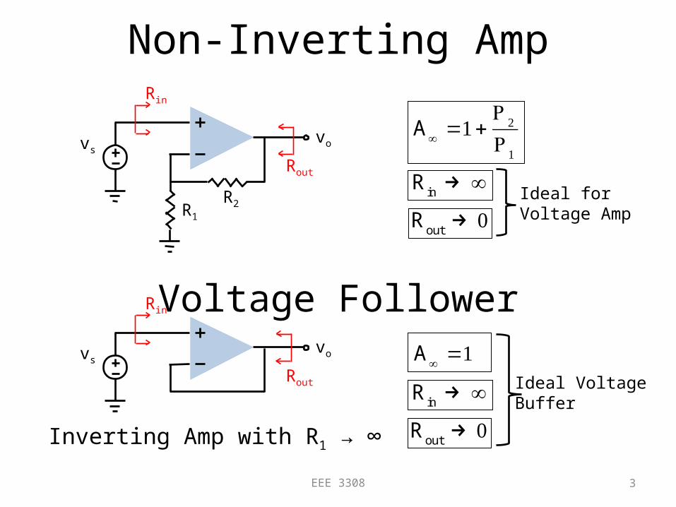
Non-Inverting Amp
3EEE 3308
R2R1
vsvo
Rout
Rin
Rin→ ∞
Ideal forVoltage Amp
Voltage Followervs
vo
Rout
Rin
A∞ =1
Rin→ ∞
Rout→ 0
Ideal VoltageBuffer
Inverting Amp with R1 → ∞
A∞ =1+
R2
R1
Rout→ 0
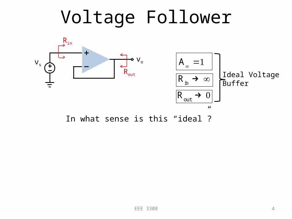
Voltage Follower
4EEE 3308
vsvo
Rout
Rin
A∞ =1
Rin→ ∞
Rout→ 0
Ideal VoltageBuffer
In what sense is this “ideal”?
Voltage Follower
5EEE 3308
vsvo
Rout
Rin
A∞ =1
Rin→ ∞
Rout→ 0
Ideal VoltageBuffer
RF
vsvo
RL
RS
Adding RS, RF or RL
reduces T but has no effect on A∞.
Still A∞ = 1.
In what sense is this “ideal”?
Inverting Amp
6EEE 3308
R2
vo
Rout
Rin
A∞ =−
R2
R1
Rin→ R1, which is not ideal.
Rout→ 0vs
R1
Ideal forVoltage Amp
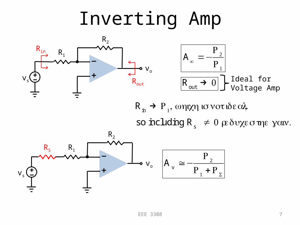
Inverting Amp
7EEE 3308
R2
vo
Rout
Rin
A∞ =−
R2
R1
Rin→ R1, which is not ideal,
Rout→ 0 Ideal for
Voltage Ampvs
R1
so including Rs ≠ 0 reduces the gain.
R2
vo
vs
R1RS
A
v≅−
R2
R1 +RS
Inverting Amp
8EEE 3308
R2
vo
Rout
Rin
A∞ =−
R2
R1
Rout→ 0 Ideal for
Voltage Ampvs
R1
RB
R2
vo
vs
R1
RC
RA
On the other hand,adding RA, RB or RC
reduces T but hasno effect on A∞ = -R2/R1
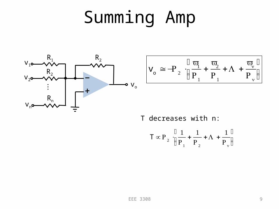
Summing Amp
9EEE 3308
R2
vo v
o≅−R2 ⋅
v1
R1
+v2
R1
+L +vn
Rn
⎛
⎝⎜⎞
⎠⎟
R1v1
R2v2
vn
Rn
.
..
T decreases with n:
I to V Converter/ Transimpedance Amp
10EEE 3308
R2
vo
Rout
Rin
A∞ =−R2
is Rin→ 0
Rout→ 0
Ideal forTransimpedanceAmp (iin, vout)
Current-Mode Outputs:Put load in series with the
feedback signal path
11EEE 3308
R2R1
vs
io
Rout
V to I Converter/Transadmittance Amp
12EEE 3308
R2R1
vs
io
Rout
iout
vs
≅A∞ =1R1
Rin→ ∞
Rout→ ∞
Ideal forTransadmittanceAmp (vin, iout)
Rin
V to I Converter/Transadmittance Amp
13EEE 3308
R2R1
vs
ioRA, RB, RC, and RD
reduce T but do notaffect A∞ = 1/R1
RA
RC
RB
RD
Current Buffer
14EEE 3308
R2
Rout
A∞ =1
is
io
Rin
Rin→ ∞
Rout→ ∞
Ideal forcurrent incurrent out
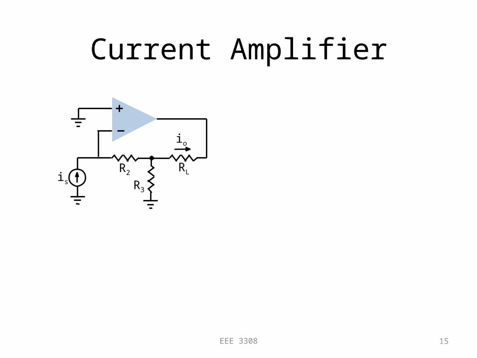
Current Amplifier
15EEE 3308
RL
R3
io
R2is
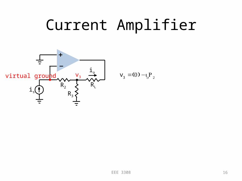
Current Amplifier
16EEE 3308
RL
R3
io
R2is
v3 v3=(0) −isR2virtual ground
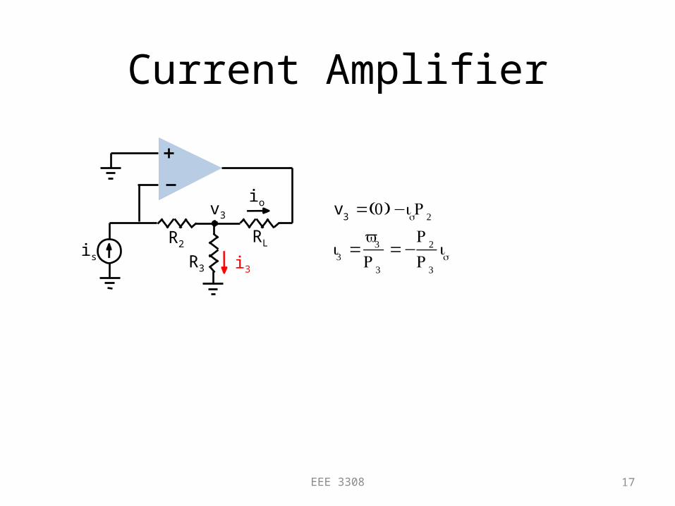
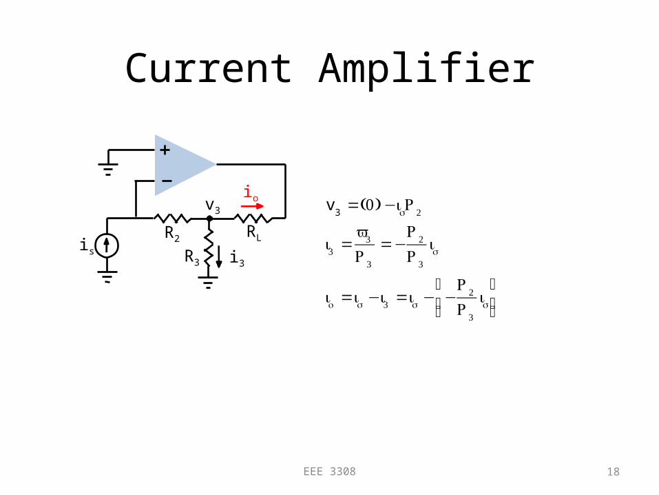
Current Amplifier
17EEE 3308
RL
R3
io
R2is
v3
i3
Current Amplifier
18EEE 3308
RL
R3
io
R2is
v3
v3=(0) −isR2
i3 =v3
R3
=−R2
R3
is
io =is −i3 =is − −R2
R3
is⎛
⎝⎜⎞
⎠⎟
i3
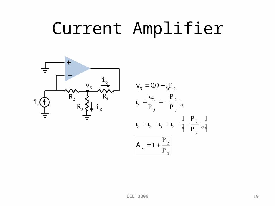
Current Amplifier
19EEE 3308
RL
R3
io
R2is
v3
v3=(0) −isR2
i3 =v3
R3
=−R2
R3
is
io =is −i3 =is − −R2
R3
is⎛
⎝⎜⎞
⎠⎟
A∞ =1+
R2
R3
i3
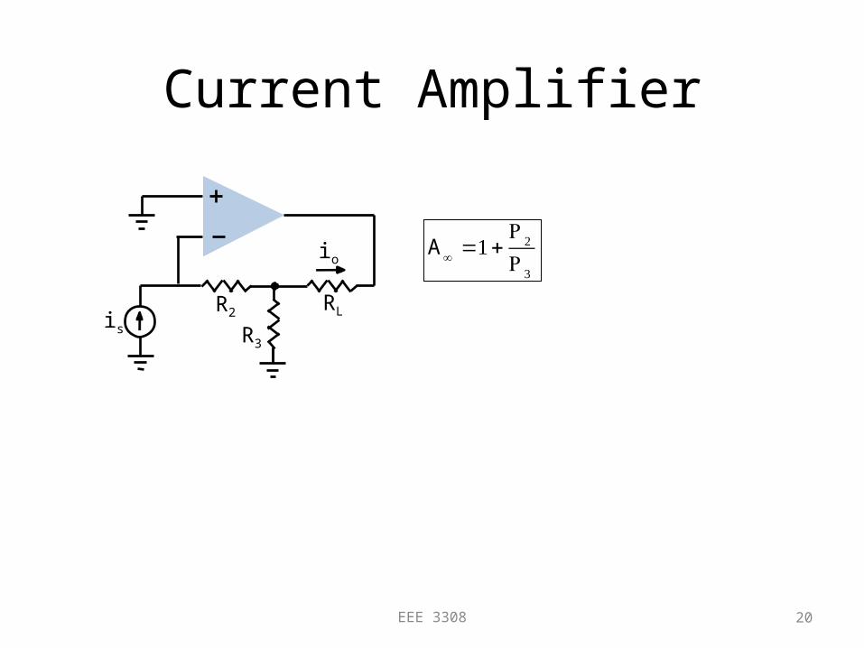
Current Amplifier
20EEE 3308
RL
R3
io
R2is
A∞ =1+
R2
R3
Current Amplifier
21EEE 3308
RL
R3
io
R2
is
RA
RSRC
RB
RO
Adding RA, RB, RC, RS, or RO
reduces T but has no effect on A∞
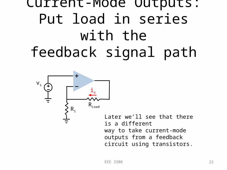
Current-Mode Outputs:Put load in series with the
feedback signal path
22EEE 3308
RLoadR1
vs
io
Later we’ll see that there is a differentway to take current-mode outputs from a feedback circuit using transistors.