27
ANALOG ELECTRONICS ANALOG ELECTRONICS II II EMT 212/4 EMT 212/4 Semester 1 2006/2007 Semester 1 2006/2007
ANALOG ELECTRONICS IIANALOG ELECTRONICS II
EMT 212/4EMT 212/4
Semester 1 2006/2007Semester 1 2006/2007
SYLLABUSSYLLABUS
1. OPERATIONAL AMPLIFIER (OP-AMP) Operation Differential amplifier Common-mode Parameters Basic op-amp Practical op-amp Data sheet
2. APPLICATIONS OF OP-AMP AND FREQUENCY RESPONSE Summing amplifier Voltage follower Comparator Integrator Differentiator Frequency response Compensation
3. FEEDBACK CIRCUITS Concepts of feedback Types of feedback connection Practical feedback circuit Feedback amplifier
SYLLABUS (cont’d)SYLLABUS (cont’d)
4. OSCILLATOR Basic operating principles of an oscillator Phase-shift Wien bridge Crystal oscillator Uni-junction
5. ACTIVE FILTERS Basic filter Filter response characteristics Low-pass filter High-pass filter Band-pass filter Band-stop filter Frequency response measurement Design of filter: Butterworth, Chebychev, Elliptic
6. VOLTAGE REGULATOR Introduction Terminology Zener diode regulator Linear IC regulator Op-amp linear IC regulator

OPERATIONAL OPERATIONAL AMPLIFIERAMPLIFIER
(OP-AMP)(OP-AMP)

OP-AMP CONCEPTOP-AMP CONCEPT
HISTORYHISTORY
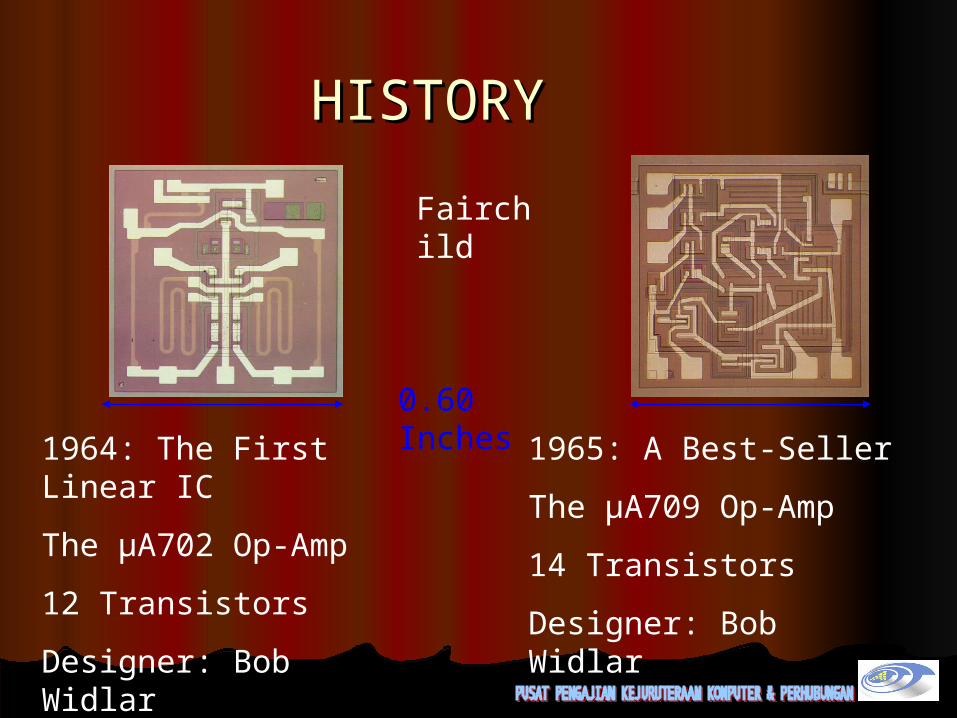
Fairchild
1964: The First Linear IC
The µA702 Op-Amp
12 Transistors
Designer: Bob Widlar
1965: A Best-Seller
The µA709 Op-Amp
14 Transistors
Designer: Bob Widlar
0.60 Inches
After Widlar left Fairchild, Dave Fullagar continued op-amp After Widlar left Fairchild, Dave Fullagar continued op-amp design and came up with the uA741 which is the most design and came up with the uA741 which is the most popular operational amplifier of all time.popular operational amplifier of all time. This design’s basic architecture is almost identical to This design’s basic architecture is almost identical to
Widlar’s 309 op-amp with one major difference: the Widlar’s 309 op-amp with one major difference: the inclusion of a fixed internal compensation capacitor. inclusion of a fixed internal compensation capacitor.
This capacitor allows the uA741 to be used without This capacitor allows the uA741 to be used without any additional, external circuitry, unlike its any additional, external circuitry, unlike its predecessors.predecessors.
The other main difference is the addition of extra The other main difference is the addition of extra transistors for short circuit protection.transistors for short circuit protection.
This op-amp has a gain of around 250,000This op-amp has a gain of around 250,000
HISTORY (cont)HISTORY (cont)

Inexpensive, efficient, versatile, and readily available building blocks for many applications Amplifier which has
Very large open loop gainDifferential input stageUses feedback to control the relationship between the input and output
WHAT IS AN OP-AMP?

WHAT DOES AN OP-AMP DO?WHAT DOES AN OP-AMP DO?
Performs many different “operations” Addition/SubtractionIntegration/DifferentiationBufferingAmplification
o DC and AC signals
x dt
dx
WHERE IS AN OP-AMP USED?WHERE IS AN OP-AMP USED?
Many applications including Comparators Oscillators Filters Sensors Sample and Hold Instrumentation Amplifier

INPUT STAGE
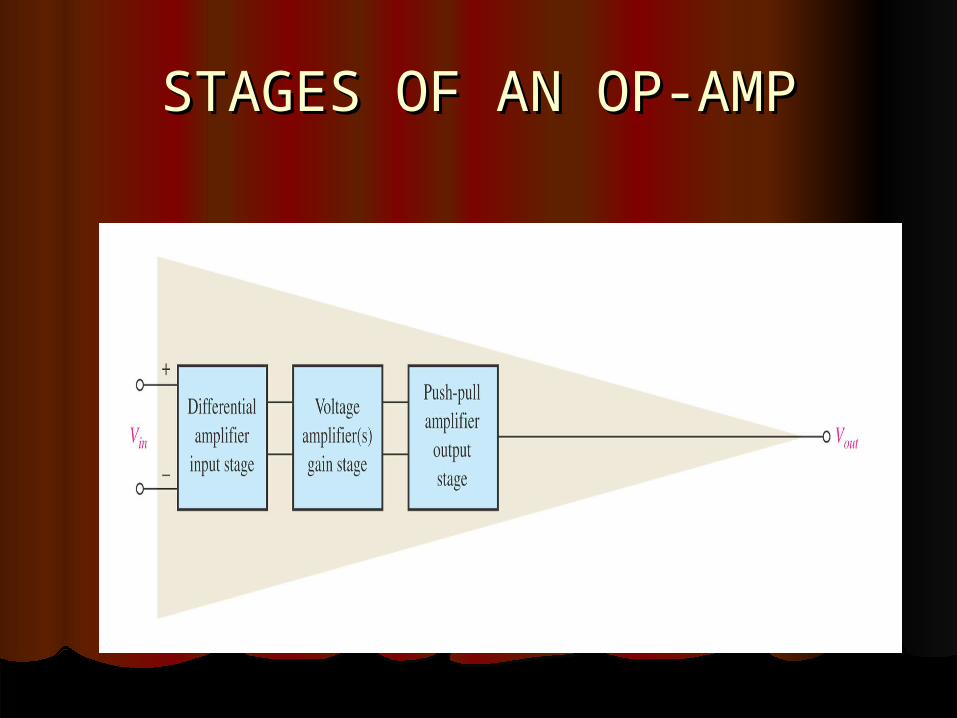
STAGES OF AN OP-AMPSTAGES OF AN OP-AMP
OUTPUT STAGE
GAIN STAGE
STAGES OF AN OP-AMPSTAGES OF AN OP-AMP
INPUT STAGEINPUT STAGE
Provides differential input for the op-amp Provides dc gain Has very high input impedance
Draws negligible input currento Enables user to utilize ideal Op-Amp equations for circuit analysis
GAIN STAGEGAIN STAGE
Provides the “gain” of the amplifier Gains up the differential signal from input and conveys it to the output stage
OUTPUT STAGEOUTPUT STAGE
Delivers current to the load Very low impedance output stage
To minimize loading the output of the op-amp May have short circuit protection
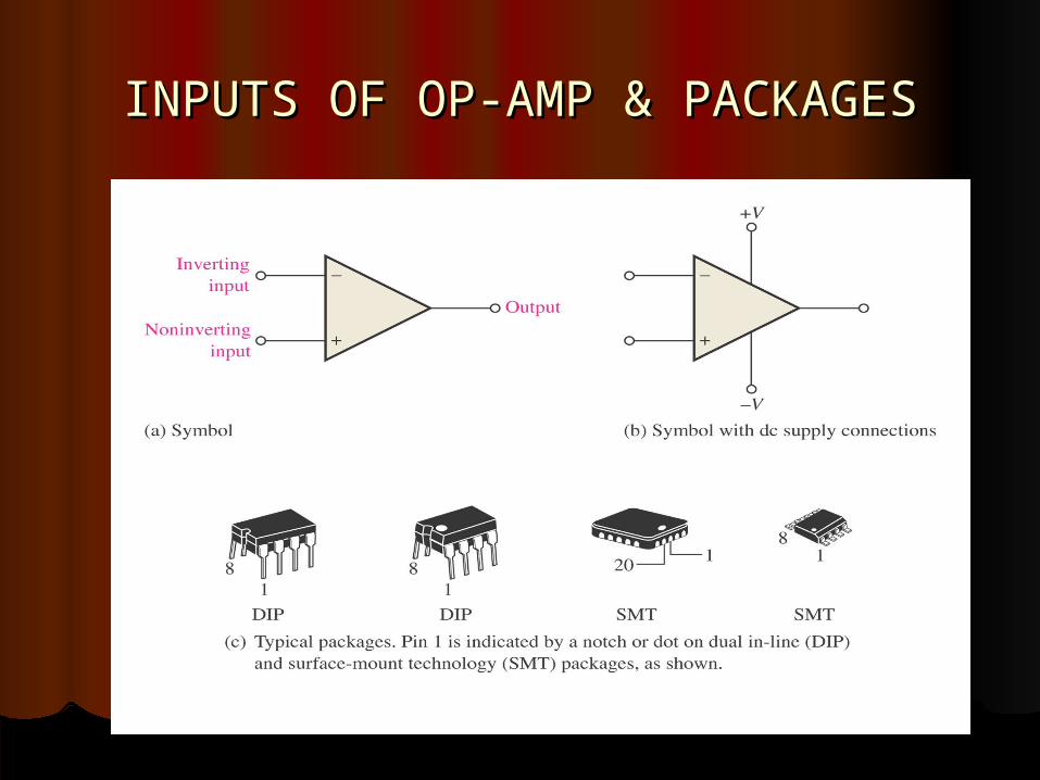
INPUTS OF OP-AMP & PACKAGESINPUTS OF OP-AMP & PACKAGES
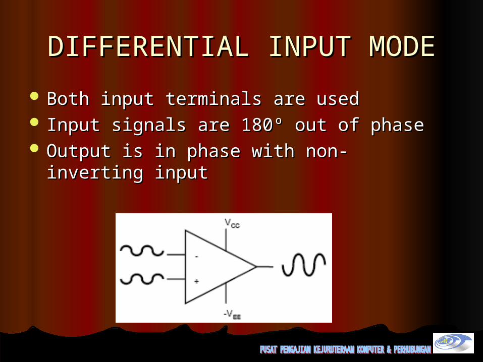
DIFFERENTIAL INPUT MODEDIFFERENTIAL INPUT MODE
Both input terminals are usedBoth input terminals are used Input signals are 180º out of phaseInput signals are 180º out of phase Output is in phase with non-inverting Output is in phase with non-inverting
inputinput
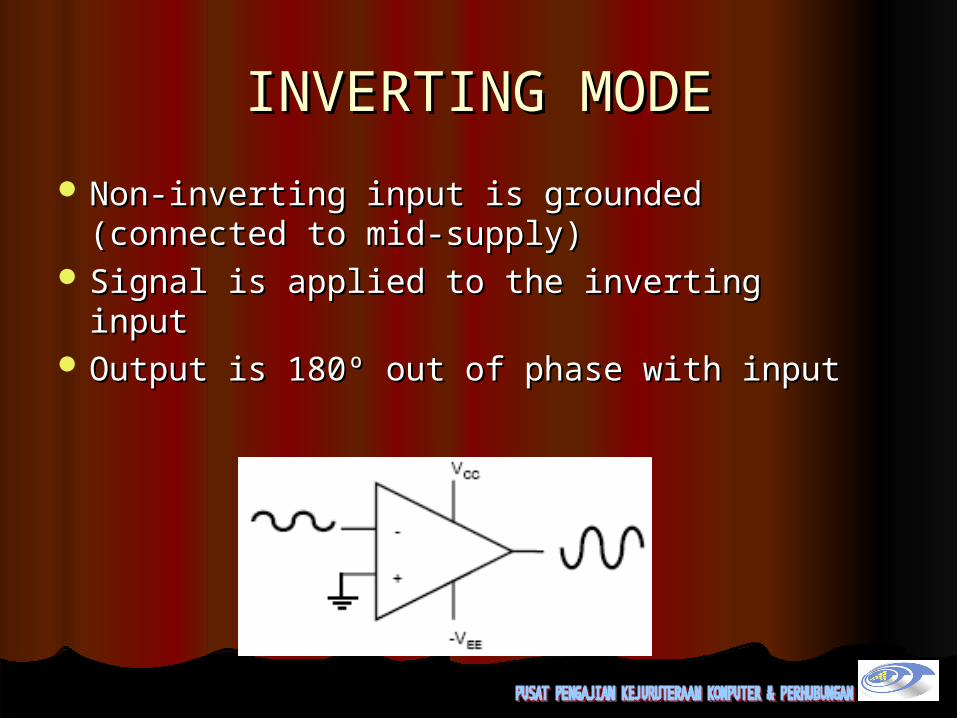
INVERTING MODEINVERTING MODE
Non-inverting input is grounded Non-inverting input is grounded (connected to mid-supply)(connected to mid-supply)
Signal is applied to the inverting inputSignal is applied to the inverting input Output is 180º out of phase with inputOutput is 180º out of phase with input

NON-INVERTING MODENON-INVERTING MODE
Inverting input is grounded (connected to Inverting input is grounded (connected to mid-supply)mid-supply)
Signal is applied to the non-inverting inputSignal is applied to the non-inverting input Output is in phase with the inputOutput is in phase with the input
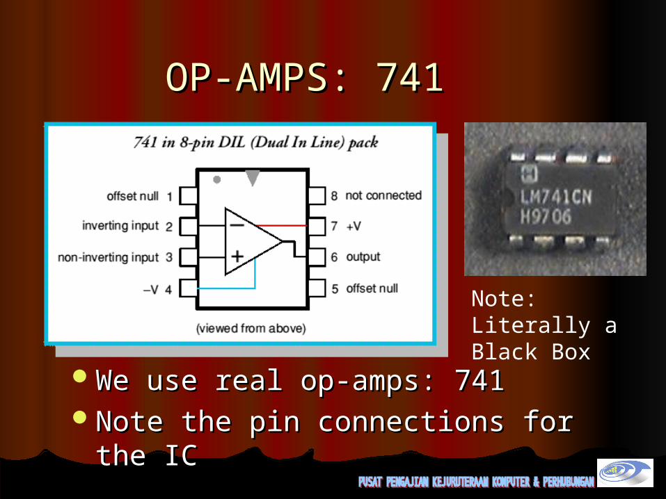
OP-AMPS: 741OP-AMPS: 741
We use real op-amps: 741We use real op-amps: 741Note the pin connections for the ICNote the pin connections for the IC
Note: Literally a Black Box
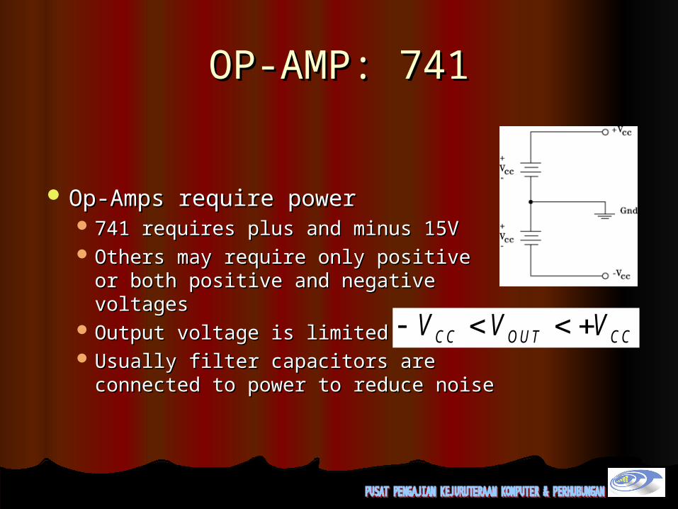
OP-AMP: 741OP-AMP: 741
Op-Amps require powerOp-Amps require power 741 requires plus and minus 15V741 requires plus and minus 15V Others may require only positive or Others may require only positive or
both positive and negative voltagesboth positive and negative voltages Output voltage is limited to Output voltage is limited to Usually filter capacitors are Usually filter capacitors are
connected to power to reduce noiseconnected to power to reduce noise
V V VCC OU T CC

OP-AMP 741(schematic)OP-AMP 741(schematic)

ICs come in many ICs come in many types of types of packages. We will packages. We will use the 8-pin, use the 8-pin, dual-in-line or DIP dual-in-line or DIP packagepackage
Note the other Note the other offset nulling offset nulling circuitcircuit

Data SheetData SheetLM741LM741

RF
RF
Data SheetData SheetLM741LM741
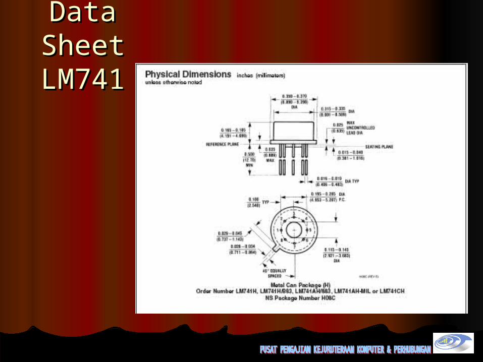
Data Data SheetSheetLM741LM741
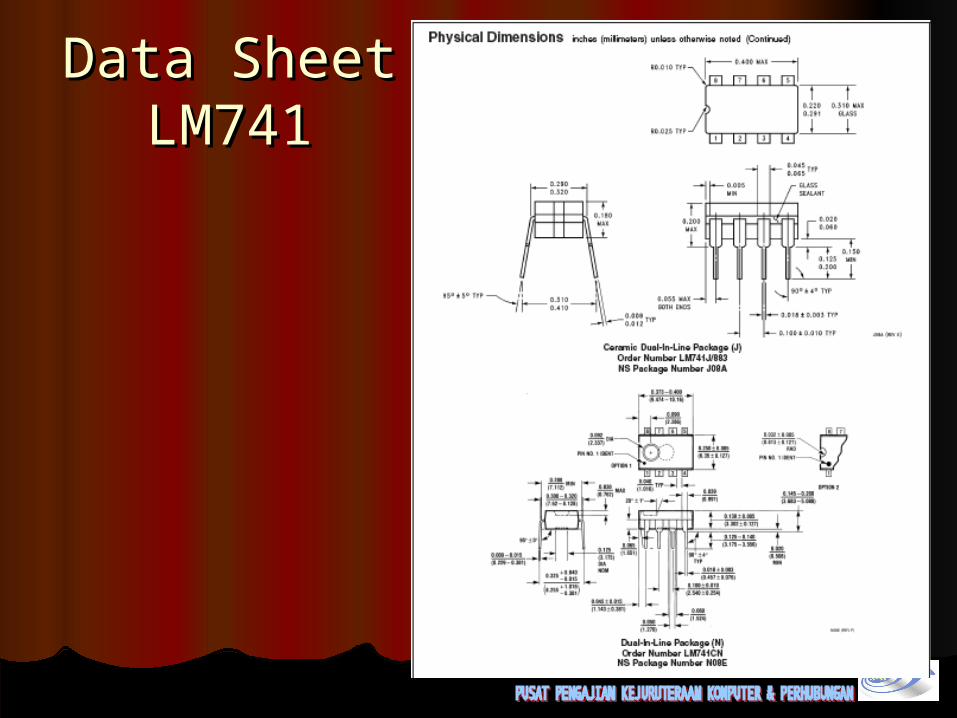
Data SheetData SheetLM741LM741


