92 The Open Materials Science Journal, 2010, 4, 92-102 1874-088X/10 2010 Bentham Open Open Access Residual Stresses in Case Hardened Materials K. Palaniradja * , N. Alagumurthi and V. Soundararajan Department of Mechanical Engineering, Pondicherry Engineering College, Pondicherry – 605 014, India Abstract: Fatigue behavior of case hardened parts depend to a great extent on the type of residual stresses developed in the components. Topography and metallurgical effects were the two elements which contribute much to surface integrity. Micro hardness of the gas carburized (EN 33 and EN 36) and Induction hardened (AISI 1040 and AISI 6150) specimens obtained during experiments, showed that there was gradual decrease of hardness from surface to sub-surface. Results also showed that more the hardness and case depth, the more was the residual stress. The optimum results gave the maximum compressive residual stress in both the gas carburizing and Induction hardening process irrespective of the mechanisms involved in the process. The X-ray diffraction test showed that the distribution of residual stress was uniform both on the surface and beneath the surface. The magnitude and distribution of residual stress obtained from the experiment agreed with the FEM results found in literatures. Keywords: Residual stress, case hardening, tensile stress, compressive stress, micro hardness. 1. INTRODUCTION In many applications, like Automobiles, heavy duty machines, et., where the machine elements are subjected fatigue loading, Gas carburized and Induction hardened components are used. Fatigue behaviour of case hardened parts depends to a great extent on the type of residual stress developed in the components. In Gas Carburizing and Induction hardening the heating and sudden cooling causes phase transformations on the surface layer and beneath the surface of the workpiece. Heat treatment temperature, Quenching Temperature, Type of Quenchant, Quenching period, heat treatment period are major variables, which influence the phase transformation [1]. Phase transformation affects the surface layer character- istics/surface integrity. The concept of surface integrity cannot be defined one dimensionally and does not only embrace the surface hardness, surface roughness, case depth or its geometrical shape, but also the characteristics of the surface and the layers directly underneath it. It comprehends the mechanical, physical-chemical, metallurgical and techno- logical properties. Surface integrity is defined as the unim- paired surface conditions, which are developed in hardware by using controlled heat treatment operations [2]. Two elements comprise the surface integrity. The first is the topography and the second is the metallurgical alternations produced at or near the surface. It thus includes dimensional accuracy, residual stresses and metallurgical damage of the heat treated component. Surface integrity assumes importance for the reasons listed below: Higher stress levels to which the materials are subjected *Address correspondence to this author at the Department of Mechanical Engineering, Pondicherry Engineering College, Pondicherry-605014, India; Tel: 91 413 2655281-287, Ext. 252,259; Fax: 91 413 2655101; E-mail: [email protected]Reliability demands are stringent Components with critical sections are becoming more in use The surface integrity of any part produced depends on The state of material before the heat treatment starts. The processing variable The energy levels during the case hardening process and The type of quenchant and rate of quenching Of all the properties that describe the surface layer characteristics residual stresses regarded as the most representative one as far as mechanical applications are concerned,. In heat treated components, residual stresses developed are due to phase transformation and non-uniform deformation during heating and cooling cycles [3]. In case of phase transformation, if the transformation is martensite to ferrite or pearlite the volume decreases hindered by the bulk material produces tensile residual stresses. If the phase transformation is ferrite to pearlite to martensite the volume increases hindered by the bulk material produces compressive residual stresses. These stresses influence the mechanical properties like fatigue strength depending on their nature, magnitude and distribution across the body. There is basically no material or situation free of this stresses. Hence, the general interest is the recognition and measurement of these residual stresses [4]. With the recent improvement on machines to measure the residual stress through XRD, the interest on the knowledge to control such stresses has increased. This interest has its importance due to the fact that the presence of the residual stress interferes with the fatigue strength of the Materials [5].
Transcript
92 The Open Materials Science Journal, 2010, 4, 92-102
1874-088X/10 2010 Bentham Open
Open Access
Residual Stresses in Case Hardened Materials
K. Palaniradja*, N. Alagumurthi and V. Soundararajan
Department of Mechanical Engineering, Pondicherry Engineering College, Pondicherry – 605 014, India
Abstract: Fatigue behavior of case hardened parts depend to a great extent on the type of residual stresses developed in
the components. Topography and metallurgical effects were the two elements which contribute much to surface integrity.
Micro hardness of the gas carburized (EN 33 and EN 36) and Induction hardened (AISI 1040 and AISI 6150) specimens
obtained during experiments, showed that there was gradual decrease of hardness from surface to sub-surface. Results
also showed that more the hardness and case depth, the more was the residual stress. The optimum results gave the
maximum compressive residual stress in both the gas carburizing and Induction hardening process irrespective of the
mechanisms involved in the process. The X-ray diffraction test showed that the distribution of residual stress was uniform
both on the surface and beneath the surface. The magnitude and distribution of residual stress obtained from the
experiment agreed with the FEM results found in literatures.
In many applications, like Automobiles, heavy duty machines, et., where the machine elements are subjected fatigue loading, Gas carburized and Induction hardened components are used. Fatigue behaviour of case hardened parts depends to a great extent on the type of residual stress developed in the components. In Gas Carburizing and Induction hardening the heating and sudden cooling causes phase transformations on the surface layer and beneath the surface of the workpiece. Heat treatment temperature, Quenching Temperature, Type of Quenchant, Quenching period, heat treatment period are major variables, which influence the phase transformation [1].
Phase transformation affects the surface layer character-istics/surface integrity. The concept of surface integrity cannot be defined one dimensionally and does not only embrace the surface hardness, surface roughness, case depth or its geometrical shape, but also the characteristics of the surface and the layers directly underneath it. It comprehends the mechanical, physical-chemical, metallurgical and techno-logical properties. Surface integrity is defined as the unim-paired surface conditions, which are developed in hardware by using controlled heat treatment operations [2]. Two elements comprise the surface integrity. The first is the topography and the second is the metallurgical alternations produced at or near the surface. It thus includes dimensional accuracy, residual stresses and metallurgical damage of the heat treated component.
Surface integrity assumes importance for the reasons listed below:
Higher stress levels to which the materials are
subjected
*Address correspondence to this author at the Department of Mechanical
The surface integrity of any part produced depends on
The state of material before the heat treatment starts.
The processing variable
The energy levels during the case hardening process
and
The type of quenchant and rate of quenching
Of all the properties that describe the surface layer characteristics residual stresses regarded as the most representative one as far as mechanical applications are concerned,. In heat treated components, residual stresses developed are due to phase transformation and non-uniform deformation during heating and cooling cycles [3]. In case of phase transformation, if the transformation is martensite to ferrite or pearlite the volume decreases hindered by the bulk material produces tensile residual stresses. If the phase transformation is ferrite to pearlite to martensite the volume increases hindered by the bulk material produces compressive residual stresses. These stresses influence the mechanical properties like fatigue strength depending on their nature, magnitude and distribution across the body. There is basically no material or situation free of this stresses. Hence, the general interest is the recognition and measurement of these residual stresses [4].
With the recent improvement on machines to measure the residual stress through XRD, the interest on the knowledge to control such stresses has increased. This interest has its importance due to the fact that the presence of the residual stress interferes with the fatigue strength of the Materials [5].
Residual Stresses in Case Hardened Materials The Open Materials Science Journal, 2010, Volume 4 93
2. RESIDUAL STRESS IN GAS CARBURIZING
The development of residual stresses, final microstructure and mechanical properties in the case and core of the carburized components depends on complex interactions among steels composition, component size and geometry, carburizing and subsequent austenitizing process parameters., heat transfer associated during quenching and time and temperature parameters of tempering.
Component geometry (size and shape) together with heat transfer associated with quenching conditions (i.e., cooling performance of the quenchant, agitation etc.,) affect the final residual stress state developed in casehardened steels as a result of quenching. Carburized microstructure is almost always tempered to transform the unstable and brittle martensite into stable tempered martensite [6, 7]. Tempering decreases residual stresses and this is promoted by increasing the tempering temperature.
With this in mind an experimental investigation is performed using EN33 (AISI 3310) and EN36 (AISI 8620) steel material to study the surface integrity issue with main focus on Residual stress in Gas Carburizing Process.
The Fig. (1) shows the measurement of residual stress in the gas carburized components. On the helix (a), groove (b), knurled region(c) and cylindrical surface (d) of the pinion material residual stresses are measured using residual stress analyzer by X-ray diffraction technique and the average
surface residual stress is taken for the analysis [8]. The residual stress beneath the top surface is measured upto a maximum depth of 1mm in the intervals of 0.1mm.
Table 1 gives the details on the materials [9, 10] subjected for Gas Carburizing (Residual stress analysis). Table 2 shows the operating parameters and their levels adopted in Gas Carburising process. Table 3 gives the experimental design matrix and Table 4, shows the test results.
The experiments have been conducted based on L27 orthogonal array system proposed in Taguchis’ Mixed level series DOE with interactions as given below:
i) Furnace Temperature vs Quenching Time (AxB)
ii) Furnace Temperature vs Tempering Temperature (AxC)
3. RESIDUAL STRESS IN INDUCTION HARDENING
In Induction hardening, the components are heated usually for a few seconds only. The hardening temperature varies from 760 – 800ºC. The major influencing variables in Induction Hardening are the Power potential, Scan speed and Quench flow rate. The process variables are having a definite relation with hardness and volume fraction of martensite of the hardened components [11]. The attainment of correct combination of surface hardness, hardness penetration depth
Fig. (1). Residual stress measurement locations on the Gas carburized component.
Table 1. Materials Used in Gas Carburizing
S. No. Type Designation Chemical Composition in Percentage Size
01 Nickel alloy steel EN 33 C-0.15%, Si-0.35%, Mn-0.60%, Cr-0.30%, Ni-3.5%, S&P each -0.05%
02 Chromium alloy steel EN 36 C-0.18%, Si-0.10%, Mn-0.30%, Cr-0.60%, Ni-3.0% S&P each – 0.05&
Diameter = 17.3 mm
Length = 150 mm
Table 2. Gas Carburizing-Operating Conditions
S. No. Variables Notation Level 1 Level 2 Level 3
1 Furnace temperature A 870°C 910°C 940°C
2 Quenching Time B 60 minutes 90 minutes 120 minutes
3 Tempering Temperature C 150°C 200°C 250°C
4 Tempering Time D 80 minutes 100 minutes 120 minutes
5 Preheating E No Preheating 150°C No Preheating
94 The Open Materials Science Journal, 2010, Volume 4 Palaniradja et al.
Table 3. Experimental Design Matrix
TRIAL A B AXB AXB C AXC AXC D E
1 1 1 1 1 1 1 1 1 1
2 1 1 1 1 2 2 2 2 2
3 1 1 1 1 3 3 3 3 3
4 1 2 2 2 1 1 1 2 2
5 1 2 2 2 2 2 2 3 3
6 1 2 2 2 3 3 3 1 1
7 1 3 3 3 1 1 1 3 3
8 1 3 3 3 2 2 2 1 1
9 1 3 3 3 3 3 3 2 2
10 2 1 2 3 1 2 3 1 2
11 2 1 2 3 2 3 1 2 3
12 2 1 2 3 3 1 2 3 1
13 2 2 3 1 1 2 3 2 3
14 2 2 3 1 2 3 1 3 1
15 2 2 3 1 3 1 2 1 2
16 2 3 1 2 1 2 3 3 1
17 2 3 1 2 2 3 1 1 2
18 2 3 1 2 3 1 2 2 3
19 3 1 3 2 1 3 2 1 3
20 3 1 3 2 2 1 3 2 1
21 3 1 3 2 3 2 1 3 2
22 3 2 1 3 1 3 2 2 1
23 3 2 1 3 2 1 3 3 2
24 3 2 1 3 3 2 1 1 3
25 3 3 2 1 1 3 2 3 2
26 3 3 2 1 2 1 3 1 3
27 3 3 2 1 3 2 1 2 1
Table 4. Gas Carburizing Test Results Materials: EN 33 and EN 36
Hardness in HRA Case Depth in mm Residual Stress in MPa S. No.
EN 33 EN 36 EN 33 EN 36 EN 33 EN 36
01 78.0 76.0 0.75 0.75 -425 -423
02 78.5 78.0 0.80 0.75 -430 -423
03 79.0 77.0 0.75 0.80 -428 -430
04 79.0 77.5 0.80 0.85 -432 -432
05 81.0 78.5 0.75 0.85 -442 -436
06 81.0 80.0 0.75 0.80 -438 -450
07 81.0 80.0 0.65 0.70 -430 -434
08 78.0 80.5 0.70 0.70 -423 -432
09 79.0 76.0 0.70 0.70 -428 -422
10 79.0 77.0 0.75 0.70 -428 -424
11 79.0 77.0 0.85 0.85 -438 -426
12 79.5 78.0 0.85 0.80 -440 -427
13 79.5 78.0 0.85 0.80 -438 -426
14 78.0 77.0 0.90 0.75 -440 -424
15 78.5 78.5 0.80 0.75 -442 -422
16 80.0 78.5 0.75 0.70 -440 -420
17 81.0 78.5 0.75 0.85 -438 -427
18 77.0 76.0 0.85 0.85 -432 -421
19 78.0 77.5 0.85 0.75 -436 -427
20 80.5 80.0 0.85 0.70 -442 -432
21 79.0 79.5 0.70 0.80 -431 -429
22 78.5 76.5 0.80 0.85 -433 -424
23 81.5 81.5 0.80 1.00 -448 -460
24 79.0 78.0 0.95 0.90 -434 -429
25 80.0 78.5 0.80 0.90 -438 -431
26 79.5 80.0 0.80 0.95 -434 -445
27 80.0 77.0 0.90 0.90 -446 -427
Residual Stresses in Case Hardened Materials The Open Materials Science Journal, 2010, Volume 4 95
(Fig. 2) contd…..
-440
-438
-436
-434
-432
-430
-428
-426
0 20 40 60 80 100 120 140
Quenching time in minutes(b)
Ave
rage
Res
idu
al s
tres
s in
MP
a EN 33 EN 36
-440
-438
-436
-434
-432
-430
-428
-426
-424
-422 860 870 880 890 900 910 920 930 940 950
Furnace Temperature in degree Celsius(a)
EN 33 EN 36
Ave
rage
Res
idu
al s
tres
s in
MP
a
-438
-436
-434
-432
-430
-428
-426
-424 0 20 40 60 80 100 120 140
Tempering time in minutes(d)
Ave
rage
Res
idu
al s
tres
s in
MP
a
EN 33 EN 36
-438
-436
-434
-432
-430
-428
-426
0 50 100 150 200 250 300
Tempering temperature in degree Celsius(c)
EN 33 EN 36
Ave
rage
Res
idu
al s
tres
s in
MP
a
96 The Open Materials Science Journal, 2010, Volume 4 Palaniradja et al.
(Fig. 2) contd…..
Fig. (2). (a-e) Process variables vs residual stress.
Fig. (3). Depth beneath the surface vs Residual stress (EN 33 - Gas
Carburizing Process).
Table 5. Residual Stress and Micro Hardness Values of the Gas Carburized Component for the Selected set of Trials Material: EN
33
Micro Hardness in VHN Residual Stress in MPa Depth Beneath the Surface in mm
Trial 5 Trial 23 Trial 5 Trial 23
Surface 610 620 -442 -448
0.1 600 614 -438 -446
0.2 595 600 -432 -442
0.3 590 594 -426 -438
0.4 585 590 -424 -434
0.5 584 587 -420 -429
0.6 582 584 -417 -426
0.7 579 576 -413 -419
0.8 572 564 -409 -415
0.9 564 561 -400 -404
1.0 550 550 +110 +119
Table 6. Residual Stress and Micro Hardness Values of the Gas Carburized Component for the Selected Set of Trials Material:
EN 36
Micro Hardness in VHN Residual Stress in MPa Depth Beneath the Surface in mm
Trial 6 Trial 26 Trial 6 Trial 26
surface 618 600 -450 -445
0.1 615 596 -446 -442
0.2 612 593 -442 -436
0.3 606 589 -437 -432
0.4 598 584 -434 -428
0.5 589 578 -429 -424
0.6 577 574 -424 -419
0.7 569 568 -419 -414
0.8 562 562 -411 -407
0.9 554 558 -401 -400
1.0 550 552 +115 +112
-436
-435
-434
-433
-432
-431
-430
-429
0 20 40 60 80 100 120 140 160
Preheating Temperature in degree Celsius(e)
EN 33 EN 36
(e)
Ave
rage
Res
idu
al s
tres
s in
MP
a
-500
-350
-200
-50
100
250
0 0.2 0.4 0.6 0.8 1 1.2
Depth beneath the surface in mm
Res
idu
al s
tres
s in
MP
a
EN 33 - Trial 5 EN 33 - Trial 23
Residual Stresses in Case Hardened Materials The Open Materials Science Journal, 2010, Volume 4 97
Fig. (4). Depth beneath the surface vs Residual stress (EN 36 - Gas
Carburizing Process).
and high magnitude of compressive residual stress with permitted level of distortion requires the use of proper and optimized process variables.
The surface residual stress and the sub-surface residual stress are of great importance on the fatigue resistance of the materials [12]. Number of researchers report that if those stresses are of compressive natures improve the resistance to fatigue whereas if those stresses are of tensile nature depending on their magnitude they contribute to a decline in the fatigue resistance [13]. In order to verify the behaviour of the residual stress in the surface and sub-surface of the Induction hardened components, experiments have been conducted.
The Fig. (5) shows the details on the measurement of residual stress in the Induction hardened components. The measurement was taken at three places, namely teeth (a), groove (b) and cylindrical surface (c). Residual stresses are measured using residual stress analyzer by X-ray diffraction technique and the average surface residual stress is taken for the analysis [14]. The residual stress beneath the top surface is measured upto a maximum depth of 1mm in the intervals of 0.1mm.
Table 7 gives the details on the materials subjected for Induction Hardening (Residual stress analysis). Table 8 shows the operating variables and their levels adopted in
Table 7. Materials Used for Induction Hardening (Residual Stress Analysis)
S. No. Type Designation Chemical Composition in Percentage Size
Factors and Treatment Factors and Treatment Factors and Treatment S. No.
P S Q S. No.
P S Q S. No.
P S Q
1 L1 L1 L1 10 L2 L1 L1 19 L3 L1 L1
2 L1 L1 L2 11 L2 L1 L2 20 L3 L1 L2
3 L1 L1 L3 12 L2 L1 L3 21 L3 L1 L3
4 L1 L2 L1 13 L2 L2 L1 22 L3 L2 L1
5 L1 L2 L2 14 L2 L2 L2 23 L3 L2 L2
6 L1 L2 L3 15 L2 L2 L3 24 L3 L2 L3
7 L1 L3 L1 16 L2 L3 L1 25 L3 L3 L1
8 L1 L3 L2 17 L2 L3 L2 26 L3 L3 L2
9 L1 L3 L3 18 L2 L3 L3 27 L3 L3 L3
-500
-350
-200
-50
100
250
0 0.2 0.4 0.6 0.8 1 1.2
Depth beneath the surface in mm
Res
idu
al s
tres
s in
MP
a EN 36 - Trial 6 EN 36 - Trial 26
98 The Open Materials Science Journal, 2010, Volume 4 Palaniradja et al.
Induction hardening process. Table 9 shows the Experimental design matrix. Tables 10-12 show the test results.
The experiments have been conducted based on 33
full factorial DOE.
4. RESULTS AND DISCUSSION
Micro hardness of the Gas carburized (EN 33 and EN 36) and Induction hardened (AISI 1040 and AISI 6150) specimens are found by using Vickers microhardness tester
and reported in the Tables 5, 6, 12 and 13. The higher hardness resulted from the outer surface is due to the formation of martensite, which is obtained during the diffusion, and phase transformation of surface layers with self-quenching. Micro hardness analysis gives that there is a gradual decrease of hardness from surface to sub-surface.
The surface hardness in HRA, case depth in mm, Residual stress in MPa for different experimental combinations of Gas carburized specimens are shown in Table 4. Study indicates that more the hardness and case
Fig. (5). Residual stress measurement locations on the Induction hardened component.
Table 10. Induction Hardening Test Results Material: AISI 1040
Factors and Treatment S. No.
P S Q
Hardness in
HRA
Distortion in
mm
Case Depth Below
the Teeth in mm
Case Depth Back
of the Bar in mm
Residual Stress
in MPa
1 L1 L1 L1 80.0 2.00 2.00 4.10 -746
2 L1 L1 L2 78.0 2.15 2.20 3.80 -736
3 L1 L1 L3 79.0 1.90 1.85 3.20 -742
4 L1 L2 L1 78.0 0.80 2.50 1.20 -747
5 L1 L2 L2 80.0 1.60 1.80 2.70 -746
6 L1 L2 L3 82.0 2.10 2.20 4.20 -750
7 L1 L3 L1 83.0 2.40 2.30 2.30 -744
8 L1 L3 L2 74.0 1.30 1.80 2.90 -734
9 L1 L3 L3 81.0 1.50 1.50 3.70 -744
10 L2 L1 L1 74.0 2.40 2.60 2.90 -727
11 L2 L1 L2 78.0 2.60 2.40 2.60 -738
12 L2 L1 L3 77.0 1.70 1.90 1.90 -734
13 L2 L2 L1 78.0 2.00 1.90 3.10 -737
14 L2 L2 L2 74.0 2.40 2.50 2.30 -727
15 L2 L2 L3 76.0 2.30 2.30 3.30 -732
16 L2 L3 L1 78.0 1.30 1.35 2.60 -741
17 L2 L3 L2 74.0 1.20 1.40 2.90 -726
18 L2 L3 L3 78.0 2.10 2.00 1.80 -734
19 L3 L1 L1 69.0 1.00 1.30 1.70 -724
20 L3 L1 L2 65.0 1.25 1.65 2.10 -721
21 L3 L1 L3 67.0 0.95 1.30 1.10 -723
22 L3 L2 L1 64.0 0.70 1.40 1.30 -723
23 L3 L2 L2 62.0 0.85 1.30 0.95 -720
24 L3 L2 L3 63.0 0.80 1.35 1.40 -722
25 L3 L3 L1 68.0 0.95 1.30 1.00 -728
26 L3 L3 L2 67.0 1.10 1.50 1.40 -724
27 L3 L3 L3 65.0 1.20 1.40 1.10 -722
Residual Stresses in Case Hardened Materials The Open Materials Science Journal, 2010, Volume 4 99
depth more will be the residual stress formed. The residual stresses formed are compressive in nature and so it may improve the fatigue strength of the material [15].
The surface hardness in HRA, Distortion in mm, Case depth below the teeth of the Rack in mm, Case depth back of the Rack in mm and Residual stress in MPa for different experimental combinations of Induction hardened specimens are shown in Tables 10 and 11.
Table 11. Induction Hardening Test Results Materials: AISI 6150
Factors and Treatment S. No.
P S Q
Hardness in
HRA
Distortion
in mm
Case Depth Below
the Teeth in mm
Case Depth Back
of the Bar in mm
Residual
Stress in MPa
1 L1 L1 L1 83.0 2.40 2.20 4.20 -804
2 L1 L1 L2 82.0 2.20 2.10 3.90 -800
3 L1 L1 L3 80.0 2.00 2.00 4.20 -794
4 L1 L2 L1 80.0 2.10 1.90 3.50 -736
5 L1 L2 L2 84.0 0.80 1.80 3.10 -738
6 L1 L2 L3 79.0 2.30 2.20 3.00 -744
7 L1 L3 L1 80.0 1.90 2.10 3.40 -796
8 L1 L3 L2 84.0 2.00 1.10 2.90 -800
9 L1 L3 L3 84.0 2.00 1.80 4.10 -805
10 L2 L1 L1 78.0 1.60 2.70 3.20 -732
11 L2 L1 L2 70.0 1.70 1.70 3.20 724
12 L2 L1 L3 73.0 1.80 1.90 3.60 -738
13 L2 L2 L1 70.0 1.25 1.60 3.40 -741
14 L2 L2 L2 76.0 2.50 1.80 3.80 -732
15 L2 L2 L3 77.0 1.60 1.30 2.10 -741
16 L2 L3 L1 73.0 1.70 1.80 2.80 -729
17 L2 L3 L2 75.0 1.30 1.70 3.70 -736
18 L2 L3 L3 74.0 1.00 1.70 3.00 -732
19 L3 L1 L1 78.0 1.30 1.40 1.80 -724
20 L3 L1 L2 70.0 0.70 1.30 1.70 -727
21 L3 L1 L3 67.0 1.30 1.30 1.50 -723
22 L3 L2 L1 68.0 1.50 1.70 0.90 -728
23 L3 L2 L2 64.0 0.90 1.60 1.40 -724
24 L3 L2 L3 67.0 0.80 1.30 1.60 -731
25 L3 L3 L1 70.0 1.10 1.40 0.90 -724
26 L3 L3 L2 69.0 0.90 1.50 1.00 -721
27 L3 L3 L3 70.0 1.25 1.30 1.20 -723
Table 12. Residual Stress and Micro Hardness Values of the Induction Hardened Component for the Selected Set of Trials
Material: AISI 1040
Micro Hardness in VHN Residual Stress in MPa Depth Beneath the Surface in mm
Trial 6 Trial 16 Trial 6 Trial 16
surface 655 649 -750 -741
0.1 644 636 -747 -738
0.2 636 627 -742 -734
0.3 625 624 -741 -731
0.4 618 615 -736 -728
0.5 612 609 -731 -724
0.6 608 605 -725 -719
0.7 604 598 -720 -714
0.8 594 587 -719 -708
0.9 591 583 -715 -702
1.0 582 574 +210 +227
100 The Open Materials Science Journal, 2010, Volume 4 Palaniradja et al.
(Fig. 6) contd…..
Fig. (6). (a-c) Process variables vs residual stress.
Fig. (7). Depth beneath the surface vs residual stress (AISI 1040
steel material - induction hardening process).
-755
-750
-745
-740
-735
-730
0 0.5 1 1.5 2 2.5
Scan speed in m/minutes(b)
Ave
rage
Res
idu
al s
tres
s in
MP
a AISI 1040 AISI 6150
-790
-780
-770
-760
-750
-740
-730
-720
0 2 4 6 8 10
Power potential in kW/ sq.inch(a)
Ave
rage
Res
idu
al s
tres
s in
MP
a
AISI 1040 AISI 6150
-748
-746
-744
-742
-740
-738
-736
-734
-732
-730
-728
0 5 10 15 20 25
Quench flow rate in litres /minutes(c)
Ave
rage
Res
idu
al s
tres
s in
MP
a
AISI 1040 AISI 6150
-1100
-800
-500
-200
100
400
0 0.2 0.4 0.6 0.8 1 1.2
Depth beneath the surface in mm
Res
idu
al s
tres
s in
MP
a
AISI 1040 - Trial 6 AISI 1040 Trial 16
Residual Stresses in Case Hardened Materials The Open Materials Science Journal, 2010, Volume 4 101
The magnitude and the nature of the residual stresses left after heat treatment at different operating conditions have been measured by the X-ray diffraction techniques using the Residual stress analyzer. Residual stress analysis indicates that Induction hardening can give a compressive residual stress of (-) 800MPa for the Low alloyed Medium carbon steels [16]. However, Gas carburising can give a compressive residual stress of (-) 400MPa for Low alloyed Low carbon steels [17].
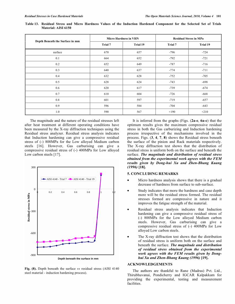
Fig. (8). Depth beneath the surface vs residual stress (AISI 4140
steel material - induction hardening process).
It is inferred from the graphs (Figs. (2a-e, 6a-c) that the optimum results gives the maximum compressive residual stress in both the Gas carburizing and Induction hardening process irrespective of the mechanisms involved in the process. Figs. (3, 4, 7, 8) shows the Residual stress beneath the surface of the pinion and Rack materials respectively. The X-ray diffraction test shows that the distribution of residual stress is uniform both on the surface and beneath the surface. The magnitude and distribution of residual stress
obtained from the experimental work agrees with the FEM
results given by Dong-hui Xu and Zhen-Bhang Kuang (1996) [18].
5. CONCLUDING REMARKS
• Micro hardness analysis shows that there is a gradual decrease of hardness from surface to sub-surface.
• Study indicates that more the hardness and case depth more will be the residual stress formed. The residual stresses formed are compressive in nature and it improves the fatigue strength of the material.
• Residual stress analysis indicates that Induction hardening can give a compressive residual stress of (-) 800MPa for the Low alloyed Medium carbon steels. However, Gas carburising can give a compressive residual stress of (-) 400MPa for Low alloyed Low carbon steels.
• The X-ray diffraction test shows that the distribution of residual stress is uniform both on the surface and beneath the surface. The magnitude and distribution
of residual stress obtained from the experimental
work agrees with the FEM results given by Dong-
hui Xu and Zhen-Bhang Kuang (1996) [19].
ACKNOWLEDGEMENTS
The authors are thankful to Rane (Madras) Pvt. Ltd., Thirubhuvanai, Pondicherry and IGCAR Kalpakkam for providing the experimental, testing and measurement facilities.
Table 13. Residual Stress and Micro Hardness Values of the Induction Hardened Component for the Selected Set of Trials
Material: AISI 6150
Micro Hardness in VHN Residual Stress in MPa Depth Beneath the Surface in mm
Trial 7 Trial 19 Trial 7 Trial 19
surface 670 657 -796 -724
0.1 664 652 -792 -721
0.2 652 649 -787 -716
0.3 640 637 -774 -711
0.4 632 628 -752 -705
0.5 628 624 -743 -698
0.6 620 617 -739 -674
0.7 610 604 -726 -668
0.8 601 597 -719 -657
0.9 596 584 -704 -643
1.0 590 567 +190 +210
-900
-600
-300
0
300
0 0.2 0.4 0.6 0.8 1 1.2
Depth beneath the surface in mm
Res
idu
al s
tres
s in
MP
a
AISI 4140 - Trial 7 AISI 4140 - Trial 19
102 The Open Materials Science Journal, 2010, Volume 4 Palaniradja et al.
REFERENCES
[1] Gergely M, Somogyi SZ, Buza G. Calculation of transformation
sequences in quenched steel components to help predict internal stress distribution. Mater Sci Technol 1985; 1: 893-8.
[2] Kamamoto S, Nishimori T, Kinoshita S. Analysis of residual stress and distortion resulting from quenching in large low-alloy steel
shafts. Mater Sci Technol 1985; (1): 798-804. [3] Rai JK, Mishra A, Rao UR. Residual stresses due to quenching
process. Int J Mach Tool Des Res 1979; 20: 1-8. [4] Mitra PK, Paul S, Chatterjee S. Treatment, structure, corrosion,
correlation of AISI 8640 Steel. IE (I) J – MM 2004; 85: 33-6. [5] Mitter W, Rammerstorfer FG, GrundlerO, Wiedner G.
Discrepancies between calculated and measured residual stresses in quenched pure iron cylinder. Mater Sci Technol 1985; 1: 793-7.
[6] Rathbun FO, Coffin LF. An experimental investigation of residual stresses in quenched flat plates. Research and Development Centre,
Schenectady, New York 1975. [7] Ravindran Nair R, Natarajan R, Rao URK. Analysis of residual
stresses due to quenching considering microstructural transformations. Int J Mach Tool Des Res 1982; 22: 309-19.
[8] Sen S, Aksakal B, Ozel A. Transient and residual thermal stresses in quenched cylindrical bodies. Int J Mech Sci 2000; 42: 2013-29.
[9] Steel products Manual tool steels. American Iron and Steel institute 1976.
[10] Suryanarayana AVK. Testing of metallic materials. New Delhi: Prentice-Hall of India 1979.
[11] Kristoffersen H, Vomacka P. Influence of process parameters for
induction hardening on residual stresses. Int J Mater Des 2001; 22: 637-44.
[12] Li YY, Chen Y. Modeling quenching to predict residual stress and microstructure distribution. Trans ASME 1988, vol. 110; pp. 373-8.
[13] Liu CC, Liu Z, Xu XJ, Chen GX, Wu JZ. Effect of stress on transformation and prediction of residual stresses. Int J Mater Sci
Technol 1998; 14: 747-50. [14] Schroder R. Influences on development of thermal and residual
stresses in quenched steel cylinders of different dimensions. Mater Sci Technol 1985; 1: 754-64.
[15] Weiner JH, Huddleston JV. Transient and residual stresses in heat treated cylinders. ASME J Appl Mech 1959; 26: 31-9.
[16] Woodard PR, Chandrasekar S, Yang HTY. Analysis of temperature and microstructure in the quenching of steel cylinders. Metallic
Mater Trans B 1999; 30B: 815-22. [17] Yuan F-R, Wu S-L. Transient-temperature and residual – stress
fields in axisymmetric metal components after hardening. Mater Sci Technol 1985; 1: 851-6.
[18] Xu Dh, Kuang ZB. A study on the distribution of residual stress due to surface induction hardening. Int J Eng Mater Technol 1996;
118: 571-5. [19] Xu D-h, Kuang Z-B. A Study on the distribution of residual stress
due to surface induction hardening. Int J Eng Mater Technol 1996; 118: 571-5.
Received: October 6, 2009 Revised: October 8, 2009 Accepted: October 27, 2009
This is an open access article licensed under the terms of the Creative Commons Attribution Non-Commercial License (http://creativecommons.org/licenses/by-nc/
3.0/) which permits unrestricted, non-commercial use, distribution and reproduction in any medium, provided the work is properly cited.