To cite this article Beyhaghi, Saman and Geoffroy, Sandrine and Prat, Marc and Pillai, Krishna M. Wicking and evaporation of liquids in porous wicks: a simple analytical approach to optimization of wick design. (2014) AIChE Journal, vol. 60 (n° 5). pp. 1930-1940. ISSN 0001-1541 Open Archive TOULOUSE Archive Ouverte (OATAO) OATAO is an open access repository that collects the work of Toulouse researchers and makes it freely available over the web where possible. This is an author-deposited version published in : http://oatao.univ-toulouse.fr/ Eprints ID : 11722 To link to this article : DOI:10.1002/aic.14353 http://dx.doi.org/10.1002/aic.14353 Any correspondance concerning this service should be sent to the repository administrator: [email protected]
Transcript
To cite this article Beyhaghi, Saman and Geoffroy, Sandrine and
Prat, Marc and Pillai, Krishna M. Wicking and evaporation of
liquids in porous wicks: a simple analytical approach to
optimization of wick design. (2014) AIChE Journal, vol. 60 (n° 5). pp.
1930-1940. ISSN 0001-1541
Open Archive TOULOUSE Archive Ouverte (OATAO)OATAO is an open access repository that collects the work of Toulouse researchers and
makes it freely available over the web where possible.
This is an author-deposited version published in : http://oatao.univ-toulouse.fr/
Eprints ID : 11722
To link to this article : DOI:10.1002/aic.14353
http://dx.doi.org/10.1002/aic.14353
Any correspondance concerning this service should be sent to the repository
Wicking is the spontaneous transport of a liquid through a
porous medium as a result of capillary suction taking place at
liquid-gas interfaces at the surface or within the porous
medium. Wick action is present in many engineering applica-
tions, such as heat pipes and capillary pumped loops,1,2 propel-
lant management devices (PMD) used in spacecraft tanks,3 as
well as in other systems made of porous sheets.4 This is also an
important phenomenon in relation with salt weathering issues
in building physics, e.g., Puyate and Lawrence.5 In almost all
these examples, wicking takes place in conjunction with evapo-
ration at the liquid-gas menisci present in the system.
Several wick-based systems are designed by consumer prod-
ucts companies to disperse vapors of volatile perfume or insect-
repellent liquids in a room. These systems, which motivate this
study, also work due to the combined action of wicking and
evaporation. As sketched in Figure 1a, the wick top in such a
system is usually exposed to the air so that the volatile liquid
can slowly diffuse from the liquid-air interface present on top
of the wick into the room air. Note that the top surface of the
wick could be in level with, higher than, or lower than the sur-
rounding casing. The evaporation phenomenon is generally
improved by using local heaters placed around the wick top
region so as to increase the saturation vapor pressure.
As the other systems mentioned previously, this type of
system poses interesting engineering and scientific questions.
In particular, we are interested in the questions concerning
the design and optimization of the system. Questions such as
the range of parameters allowing the system to operate with
a fully liquid-saturated wick, or the parameters maximizing
the wick action, are of interest in many systems. In this arti-
cle, those questions are addressed for the particular system
sketched in Figure 1a. It should be clear, however, that
many of the results obtained in the course of the study of
this particular type of systems are of broader interest.
The wicks used in consumer products applications for dis-
charging perfume or other volatile compounds in the air are
generally made by sintering. Sintering is a common indus-
trial process for making porous wicks. For example, wicks
Correspondence concerning this article should be addressed to K. M. Pillai [email protected].
sintered out of beads of copper or other metals are employed
in heat pipes that are used for temperature-control applica-
tions.6,7 For our system, the wick is generally obtained by
sintering beads made of polymers such as polyethylene or
polypropylene. This type of wick has been studied theoreti-
cally and experimentally in previous efforts. Masoodi et al.8
developed a new model for wicking in such polymer wicks
based on the single-phase Darcy’s law after employing a
suction pressure at the moving liquid interface. Beyhaghi
et al.9 studied the mass transport and evaporation of nondi-
lute multicomponent liquid mixtures in the same wick. A
polymer sintered wick typical of the systems considered in
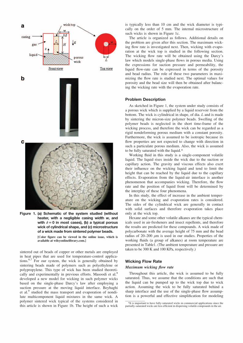
this article is shown in Figure 1b. The height of such a wick
is typically less than 10 cm and the wick diameter is typi-
cally on the order of 5 mm. The internal microstructure of
such wicks is shown in Figure 1c.
The article is organized as follows. Additional details on
the problem are given after this section. The maximum wick-
ing flow rate is investigated next. Then, wicking with evapo-
ration at the wick top is studied in the following section.
The wicking flow rate will be obtained using the Darcy’s
law which models single-phase flows in porous media. Using
the expressions for suction pressure and permeability, the
liquid flow-rate can be expressed in terms of the porosity
and bead radius. The role of these two parameters in maxi-
mizing the flow rate is studied next. The optimal values for
porosity and the bead size will then be obtained after balanc-
ing the wicking rate with the evaporation rate.
Problem Description
As sketched in Figure 1, the system under study consists of
a porous wick which is supplied by a liquid reservoir from the
bottom. The wick is cylindrical in shape, of dia. L and is made
by sintering the micron-size polymer beads. Swelling of the
polymer beads is neglected in the short time-frame of the
wicking process, and therefore the wick can be regarded as a
rigid nondeforming porous medium with a constant porosity.
Furthermore, the wick is assumed to be isotropic because its
flow properties are not expected to change with direction in
such a particulate porous medium. Also, the wick is assumed
to be fully saturated with the liquid.*
Working fluid in this study is a single-component volatile
liquid. The liquid rises inside the wick due to the suction or
capillary action. The gravity and viscous effects also exert
their influence on the wicking liquid and tend to limit the
height that can be reached by the liquid due to the capillary
effects. Evaporation from the liquid-air interface is another
phenomenon that accompanies wicking. Therefore, the flow
rate and the position of liquid front will be determined by
the interplay of these four phenomena.
In this study, the effect of increase in the ambient temper-
ature on the wicking and evaporation rates is considered.
The sides of the cylindrical wick are generally in contact
with solid surfaces and therefore evaporation takes place
only at the wick top.
Hexane and some other volatile alkanes are the typical chem-
icals used in air-fresheners and insect repellents, and therefore
the results are predicted for these compounds. A wick made of
polycarbonate with the average height of 75 mm and the bead
radius of 20–200 lm is used in our studies. Properties of the
working fluids (a group of alkanes) at room temperature are
presented in Table1. (The ambient temperature and pressure are
taken to be 300 K and 100 KPa, respectively.)
Wicking Flow Rate
Maximum wicking flow rate
Throughout this article, the wick is assumed to be fully
saturated. Thus, we assume that the conditions are such that
the liquid can be pumped up to the wick top due to wick
action. Assuming the wick to be fully saturated behind a
sharp interface and the use of the single-phase flow assump-
tion is a powerful and effective simplification for modeling
Figure 1. (a) Schematic of the system studied (without
heater, with a negligible casing width w, and
with d5 0 in most cases), (b) a typical porous
wick of cylindrical shape, and (c) microstructure
of a wick made from sintered polymer beads.
[Color figure can be viewed in the online issue, which isavailable at wileyonlinelibrary.com.]
*It is important to have fully-saturated wicks in commercial applications since thepartially-saturated wicks are less efficient in dispersing volatile compounds in the air.
wicking in industrial wicks.10 Using Darcy’s law, the flow
rate through the wick can be expressed as
Q52AK
l
@P‘
@z1qg
� �
(1)
where A is the cross-section area of the wick, K is the
porous medium permeability, l is the dynamic viscosity of
the liquid, q is the liquid density, P‘ is the pressure in the
liquid, and z is the vertical coordinate as shown in Figure
1a. In the aforementioned equation, the gravitational term
has the same sign as the pressure gradient, because the posi-
tive z-direction is chosen upward in Figure 1. Noting that P‘
� Patm at z5 0 (after assuming a hydrostatic pressure distri-
bution in the liquid surrounding the wick bottom), where
Patm is the atmospheric pressure, Eq.1 can be expressed as
Q52AK
l
P‘ðHÞ2Patm
H1qg
� �
(2)
Note that linear pressures drop within the wick, which is
employed in the derivation of (2) from (1), is a direct conse-
quence of the conservation of mass principle, i.e., dQdz50
The menisci in the pores at the wick top-surface are
curved so as to provide the capillary pumping effect. As a
result, the liquid pressure at z5H can be expressed using
the Laplace’s law as
P‘ðHÞ � Patm22c
n(3)
where, for simplicity, we have assumed axisymmetrical
menisci at the wick top; c is the liquid surface-tension, and n
is the menisci curvature radius, which is assumed to be the
same for all menisci. This eventually leads to express (2) as
Q5AK
l
2c
nH2qg
� �
(4)
The menisci radius n cannot be lower than a certain value,
which corresponds to the invasion capillary-pressure thresh-
old Ps. When the pressure difference between the gas and
the liquid at a meniscus exceeds Ps, the meniscus recedes
into the porous medium, and, therefore, ceases to be present
at the porous surface. For a random packing of monodisperse
beads of radius Rb, the capillary pressure threshold or maxi-
mum suction pressure can be expressed using an energy-
balance model, obtained after equating the release of surface
energy to viscous dissipation,8,11 as
Ps53ð12eÞccos h
eRb
(5)
Here e is the wick porosity, and h is the contact angle for
the air-liquid wick material system (h should be regarded as
the receding contact angle). Hence, the minimum menisci
radius that is compatible with a fully saturated wick would be
nmin52 eRb
3ð12eÞcos h (6)
which is obtained after taking Ps52c=nmin . As a result, after
using (6) with (4), the maximum flow rate the wick can
pump is given by
Qmax5AK
l
3ð12eÞc cos heHRb
2qg
� �
(7)
There are several models reported in the literature where
the permeability of a porous medium is expressed as a func-
tion of porosity.12 The authors have chosen to use the gen-
eral form of the Kozeny-Carman model13,14 due to the
inclusion of bead size as well as porosity
K5Ce3R2
b
ð12eÞ2(8)
Several different values for the coefficient C are available
in the literature, e.g., MacDonald et al.15 For the sintered
wicks considered in this study, the corresponding permeabil-
ities were measured by a falling head permeameter.8 The
value of fitting parameter C for each wick was determined
after matching the measured permeability with the Kozeny-
Carman formula and was found to be unique for each wick.
Although the parameter C was found to be slightly lower
than the classical value of 4/180,15 it can be concluded from
these experiments that the Kozeny-Carman model with the
classical value C5 4/180 predicts the wick permeability rea-
sonably well. As shown by (8), the Kozeny-Carman perme-
ability varies as the square of bead radius, whereas its
variation with porosity (in the constant bead radius case)†
increases slowly for porosities up to around 0.8 and then
diverges as e !1. These results will be used below to
explain the behavior of the wicking flow-rate at different
porosities and bead radii. Combining (7) and (8) finally
yields
Qmax5ACe3R2
b
ð12eÞ2l3ð12eÞc cos h
eHRb
2qg
� �
(9)
Equilibrium bead-radius (corresponding to Qmax5 0
at the wick top)
We define the equilibrium bead-radius Rb.eq, to correspond
to a pure hydrostatic equilibrium with the top menisci at
their minimum radius of curvature. Under such a situation,
Table 1. Properties of the Working Fluids used in this Study
†The bead radius and porosities may be related in real sintered wicks, but for anideal porous medium made of perfectly-spherical monodisperse particles, the two willbe independent of each other for a given packing arrangement.
the liquid in the imbibed liquid-column is not moving and
the upward pull on liquid column by the suction pressure is
balanced exactly by the downward weight of the column.
The net flow rate at the wick top is zero, and the equilibrium
bead-radius can be obtained as
Qmax5ACe3 R2
b:eq
ð12eÞ2l3ð12eÞc cos h
eHRb:eq2qg
� �
50
! Rb:eq53ð12eÞc cos h
eHqg
(10)
For a wick made of polymer beads and a group of alkanes
(C6H14, C8H18, C10H22, C12H26 and C16H34) as the working
fluids, the equilibrium bead radius is plotted in Figure 2a as
a function of porosity. While there is an observable differ-
ence between the curves at small porosities, the differences
are almost negligible for porosities greater than 0.4.
The same study has been done for a wick made of poly-
mer beads with the porosity e equal to 0.45, where the equi-
librium bead-radius Rb.eq is plotted as a function of wick
height H in Figure 2b. For such a series of curves where the
wick is supposed to work for all the liquids of interest, the
lowest curve (hexane) should be considered for the determi-
nation of the equilibrium bead radius.
It is evident from (10) and Figure 2 that Rb.eq is inversely
proportional to the porosity and the wick height, i.e., taller
or “more porous” the wick, smaller the equilibrium bead-
radius. Note that the suction pressure, as given by (5), is
inversely proportional to the bead radius Rb; so as the bead
size becomes smaller, the suction pressure becomes larger,
and taller columns of liquid can be held up under these
conditions.
One can extrapolate the reasoning to claim that for a wick
with bead radius less than Rb.eq for a given wick height H,the wick will be able to pump the liquid with the menisci
attached at the wick top, whereas this is not possible for
larger bead size.‡ So for Rb�Rb.eq for a given height, the
wick is expected to remain fully wet although there will not
be any wicking flow. The menisci at the top simply adjust
their curvatures so that the capillary forces balance the grav-
ity forces. The radius of curvature for menisci can then be
estimated from (4) as
n52c
qgH(11)
Optimal bead radius
From Eq. 9, we can see that the flow rate is a function of
the bead radius in the form of a second degree polynomial.
As a result, the bead size corresponding to the maximum
flow rate, which the wick is capable of pumping through
capillary suction to the wick top, is given by
dQmax
dRb
50 ! Rb:opt53ð12eÞc cos h
2eHqg! Rb:opt5
Rb:eq
2(12)
i.e., the optimal bead-radius is half of the hydrostatic equilib-
rium bead-radius.
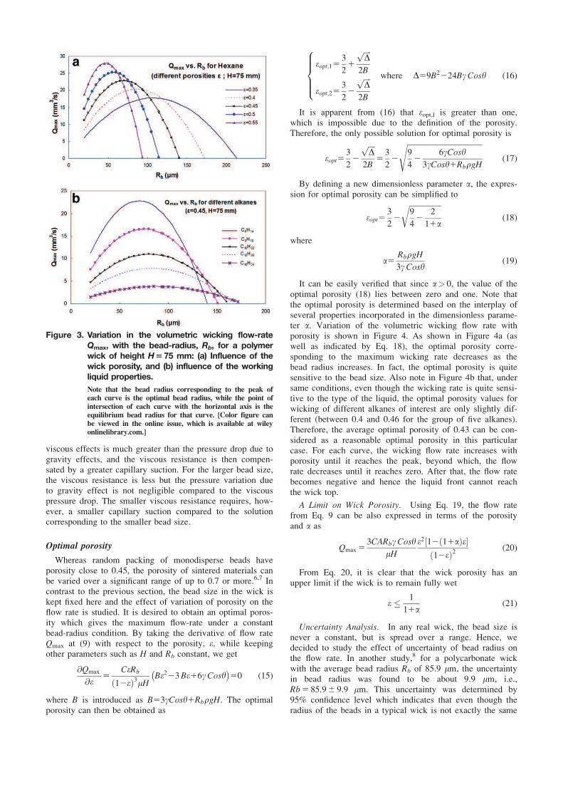
For a wick made of polycarbonate beads and with a height
H, of 75 mm, the variation of the flow rate with bead radius
as predicted by (9) is shown in Figure 3. In Figure 3a, the
influence of porosity on flow rate of hexane is shown, whereas
in Figure 3b, the porosity is set to 0.45, and the flow rate for
five different alkanes is shown. It is evident that the maximum
flow rate increases while the optimal bead radius decreases as
the porosity increases. Figure 3b shows that with the same
porosity, the wicking flow is significantly smaller for “heavier”
alkanes (except for a limited bead radius range). Note that the
plots are shown only for realistic values; i.e., for Rb greater
than 20 lm and for positive values of Qmax.
It is insightful to attempt some sort of nondimensionaliza-
tion to present the equations in a different light. After
expressing (9) for the maximum flow rate (QMAX) in terms
of Rb.opt, Qmax in (9) can be presented in terms of the dimen-
sionless flow rate Q*, as
Q�5
Qmax
QMAX
5Rb2FRb
2
Rb:opt2FRb:opt2
where F5eHqg
3ð12eÞccosh51
Rb:eq
(13)
On introducing r5Rb/Rb.eq and after applying Eq.10 into
Eq.13, Q* can finally be reduced to the following elegant
quadratic form
Q�5
Qmax
QMAX
54ðr2r2Þ (14)
Interpretation of the two roots of Eq.14 is clear. A given
flow rate Qmax, can be obtained with two different sizes of
beads. For the smaller bead size, the pressure drop due to
Figure 2. For a wick made of polycarbonate, and one
out of a group of five alkanes as the wicking
liquid, the relationship between the equilib-
rium bead-radius Rb.eq and (a) the wick
porosity for a wick with the height H of 75
mm, and (b) the wick height for a wick with
the porosity of 0.45.
‡For Rb>Rb.eq, the liquid front will not reach the wick top.
viscous effects is much greater than the pressure drop due to
gravity effects, and the viscous resistance is then compen-
sated by a greater capillary suction. For the larger bead size,
the viscous resistance is less but the pressure variation due
to gravity effect is not negligible compared to the viscous
pressure drop. The smaller viscous resistance requires, how-
ever, a smaller capillary suction compared to the solution
corresponding to the smaller bead size.
Optimal porosity
Whereas random packing of monodisperse beads have
porosity close to 0.45, the porosity of sintered materials can
be varied over a significant range of up to 0.7 or more.6,7 In
contrast to the previous section, the bead size in the wick is
kept fixed here and the effect of variation of porosity on the
flow rate is studied. It is desired to obtain an optimal poros-
ity which gives the maximum flow-rate under a constant
bead-radius condition. By taking the derivative of flow rate
Qmax at (9) with respect to the porosity, e, while keeping
other parameters such as H and Rb constant, we get
@Qmax
@e5
CeRb
ð12eÞ3lHBe223Be16cCoshÿ �
50 (15)
where B is introduced as B53cCosh1RbqgH. The optimal
porosity can then be obtained as
eopt;153
21
ffiffiffiffi
Dp
2B
eopt;253
22
ffiffiffiffi
Dp
2B
where D59B2224BcCosh
8
>
>
>
<
>
>
>
:
(16)
It is apparent from (16) that eopt,l is greater than one,
which is impossible due to the definition of the porosity.
Therefore, the only possible solution for optimal porosity is
It can be easily verified that since a> 0, the value of the
optimal porosity (18) lies between zero and one. Note that
the optimal porosity is determined based on the interplay of
several properties incorporated in the dimensionless parame-
ter a. Variation of the volumetric wicking flow rate with
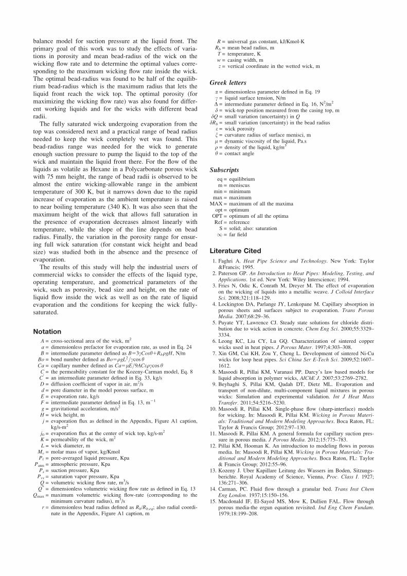
porosity is shown in Figure 4. As shown in Figure 4a (as
well as indicated by Eq. 18), the optimal porosity corre-
sponding to the maximum wicking rate decreases as the
bead radius increases. In fact, the optimal porosity is quite
sensitive to the bead size. Also note in Figure 4b that, under
same conditions, even though the wicking rate is quite sensi-
tive to the type of the liquid, the optimal porosity values for
wicking of different alkanes of interest are only slightly dif-
ferent (between 0.4 and 0.46 for the group of five alkanes).
Therefore, the average optimal porosity of 0.43 can be con-
sidered as a reasonable optimal porosity in this particular
case. For each curve, the wicking flow rate increases with
porosity until it reaches the peak, beyond which, the flow
rate decreases until it reaches zero. After that, the flow rate
becomes negative and hence the liquid front cannot reach
the wick top.
A Limit on Wick Porosity. Using Eq. 19, the flow rate
from Eq. 9 can be also expressed in terms of the porosity
and a as
Qmax53CARbcCosh
lH
e2 12ð11aÞe½ �ð12eÞ2
(20)
From Eq. 20, it is clear that the wick porosity has an
upper limit if the wick is to remain fully wet
e � 1
11a(21)
Uncertainty Analysis. In any real wick, the bead size is
never a constant, but is spread over a range. Hence, we
decided to study the effect of uncertainty of bead radius on
the flow rate. In another study,8 for a polycarbonate wick
with the average bead radius Rb of 85.9 lm, the uncertainty
in bead radius was found to be about 9.9 lm, i.e.,
Rb5 85.96 9.9 lm. This uncertainty was determined by
95% confidence level which indicates that even though the
radius of the beads in a typical wick is not exactly the same
Figure 3. Variation in the volumetric wicking flow-rate
Qmax, with the bead-radius, Rb, for a polymer
wick of height H5 75 mm: (a) Influence of the
wick porosity, and (b) influence of the working
liquid properties.
Note that the bead radius corresponding to the peak ofeach curve is the optimal bead radius, while the point ofintersection of each curve with the horizontal axis is theequilibrium bead radius for that curve. [Color figure canbe viewed in the online issue, which is available at wileyonlinelibrary.com.]
everywhere and has a random distribution, we can be confi-
dent that 95% of the particles have the radius that falls in
the range 85.9–9.9 lm�Rb� 85.919.9 lm. It should also
be noted that the “95% confidence-level” corresponds to the
portion of the measured beads whose radius falls within two
standard deviations from the mean value of all the beads.16
It is expected that the uncertainty in bead radius propagates
into the flow rate Qmax. The confidence level of the flow rate
will be the same as the one for the bead radius. Neglecting the
uncertainty in calculation of the other involving parameters,
the uncertainty in flow rate dQmax can be obtained as
dQmax5dRb
@Qmax
@Rb
5dRb
CAe3
ð12eÞ2l3ð12eÞccos h
eH22qgRb
� �
(22)
The uncertainty due to the possible random variations in
bead radius is exemplified by showing the flow rate-porosity
curve for flow of hexane in a 75-mm wick. The scatter bar
at each porosity value is calculated from Eq. 22 and the
results are shown in Figure 4c. We can be confident that the
flow rate at each porosity level is somewhere along the 95%
scatter bar. It is clear that at higher porosities, the scatter in
the flow rate becomes larger and hence the flow rate
becomes less predictable.
Flow rate as a function of porosity and bead radius
From Eq. 9, the maximum flow rate that a wick of given
height H can pump is eventually given by
QMAX5MaxðQmax Þ5ACe3R2
b
ð12eÞ2l3ð12eÞccos h
eHRb
2qg
� �
(23)
with the bead radius and porosity to be selected as Rb5Rb:opt
53ð12eÞccos h
2eHqgfrom (12), and e5eopt5
322
ffiffiffiffiffiffiffiffiffiffiffiffiffiffi
942
211a
q
from (18),
and where a5Rb:optqgH
3cCoshas given in (19). The trend of curves
shown in Figures 3a and 4a with variation of bead radius
and porosity reveals that the maximum wicking flow rate
can be achieved for extremely low-bead radii, and which
leads mathematically to e5 1 as the optimum porosity. Note
that the use of Kozeny-Carman model for porous media with
porosities close to one is not likely to be valid. Depending
on the particular structure of the considered porous medium,
e.g., fibrous materials or metal foams which are two exam-
ples of potentially highly porous materials, a more appropri-
ate relationship can be selected to obtain more accurate
results following the same procedure as proposed in this arti-
cle In fact, the physically acceptable solution is to take the
upper bound in porosity for this type of material, i.e.
e5emax � 0:7,7 which finally gives the optimum radius
Rb5Rb:OPT53ð12emax Þccos h
2eHqg. For H of 75 mm and with Hexane
as the wicking liquid, this gives Rb5Rb:opt � 25lm. How-
ever, as pointed out by the uncertainty analysis, (see Figure
4c), it is safer to select porosity slightly lower than the opti-
mal porosity so as to limit the effect of a possible dispersion
in the bead size.
Wicking with Evaporation from Wick Top
The optimal design of the wick in the absence of evapora-
tion was investigated in the previous sections. We now wish
to determine the conditions for which the liquid pumped by
capillary force can balance the evaporation at the wick top.
Transport mechanisms observed in this problem are (1) vis-
cous wicking flow of the liquid due to the effect of the capil-
lary suction, and (2) evaporation of the liquid from the wick
top surface, as studied in this section. The gravity effects
have also to be taken into account. A similar problem has
recently been studied theoretically and experimentally in
Yiotis et al.17,18 where evaporation and capillary action were
coupled. Note, however, that the main focus of this work is
on the optimization of wick design using the geometrical
parameters of particle size and porosity.
In the following part of the article, the conditions which
lead to full saturation of the wick in the presence of evapora-
tion from the top are investigated. Effect of three important
wick parameters, i.e., bead radius, porosity, and wick height,
will be studied separately, and the constraints associated
Figure 4. Variation in the wicking flow-rate Qmax, with
the porosity for a wick made of polymer
beads and having a height H of 75 mm: (a)
Influence of bead radius on the optimal
porosity, (b) influence of the liquid type on
the wicking rate and optimal porosity, and (c)
influence of uncertainty in bead radius on the
wicking rate.
[Color figure can be viewed in the online issue, which isavailable at wileyonlinelibrary.com.]
with each of them will be presented, in the subsequent
subsections.
Estimate of evaporation rate E
In order to analyze the impact of evaporation on wicking,
an estimate of evaporation rate is needed. From some previ-
ous efforts, it is known that a porous surface behaves as a
fully wetted surface provided that the pore size d and the
mean distance between pores are sufficiently small compared
to the characteristic length of external mass transfer. In clas-
sical convective drying situations, this length scale is typi-
cally the mass boundary-layer thickness.19,20 Here, the mass
transfer is dominated by diffusion with possible mild free-
convection effects and the relevant length scale is L, that isthe size of the open side (see Eq. 24). It was recently shown
that the porous surface behaves as a fully wetted surface if
the pore size d is sufficiently smaller than size of the porous
surface L.21 The numerical simulation results reported
therein suggest that this approximation is reasonable when
the ratio L/d is greater than about 10 (assuming that the
mean distance between pore is of the same order of magni-
tude as the mean pore size). As can be seen from Figure 1c,
which shows the case of the largest beads considered in this
study, this condition is satisfied for the porous wicks under
consideration in this effort. Thus, the evaporation rate can be
estimated as if the top surface of the wick was actually
entirely covered by a thin liquid film.
The evaporation rate then depends on the condition of the
surrounding air. Consider first the case where the top surface
of the wick is in level with the surrounding casing (d5 0,
see Figure 1a). A lower limit can be obtained by assuming
an evaporation process controlled by diffusion alone22 as
E5aDLMv
RTPvsðTÞ (24)
where Mv, R, T, D and Pvs are the molar mass of the vapor,
the gas constant, the temperature, the vapor molecular diffu-
sion coefficient, and the saturation pressure, respectively.
Note that the vapor concentration in the far field is supposed
to be zero. In Eq. 24, a is a numerical factor. For a circular
liquid disk of dia. L on a surface of infinite lateral extension,
a5 a15 2.22
However, the external mass transport given by (24) with a� 2 only represents a lower bound to the evaporation rate
when the wick top is in level with the casing. As reported in
Kelly-Zion et al.23 the free-convection effects significantly
increase the evaporation rate when the disk size is on the
order of a few millimeters or more. According to the results
reported in Kelly-Zion et al.23 Enet/E(a5 2) �2. Hence, for a
disk of 5 mm dia., there is about a 100% increase in the
evaporation rate (i.e., a � 4) due to the free-convection
effects compared to the prediction assuming a pure diffusive
transport of the vapor. Naturally, in real situations, the evap-
oration flux can be even greater because of the convection
effects arising due to other causes (e.g., air currents, etc.).
For simplicity, we assume the evaporation to be occurring in
a quiescent atmosphere in this article, and, thus, use (24) to
estimate the evaporation rate, but with a � 4, so as to take
into account the free-convection effect.
Range of bead-radius that ensures full wick saturation
In order for the liquid to stay at the wick top, the maxi-
mum wicking mass flow rate that the wick is potentially able
to pump should be equal to or greater than the evaporation
rate. This constraint can be expressed as qQmax � E. The
evaporative operating limit of the wick corresponds to the
extreme case of the evaporation rate as large as the maxi-
mum wicking flow rate. The evaporation limit, thus, corre-
sponds to qQmax5E which by using (9) can be expressed as
ACqe3R2
b
ð12eÞ2l3ð12eÞccos h
eHRb
2qg
� �
5E (25)
Rearranging and nondimensionalization of (25) leads to
r2r25CaBoH
L
� �2
(26)
where the dimensionless bead radius r, is defined as r5Rb/
Rb.eq. The capillary number Ca, characterizing the competi-
tion between the capillary and viscous forces is given by
Ca5lE=9ACeqccos h, while the bond number characterizing
the competition between the capillary and gravity forces is
expressed as Bo5qgL2=ccos h. Two possible solutions of Eq.
For the maximum wicking rate to be greater than the
evaporation rate, Eq. 27 changes to an inequality of the form
r2r2 � CaBoH
L
� �2
(28)
where r1 and r2 represent the limiting points where the maxi-
mum mass flow rate due to wicking becomes exactly equal
to the evaporation rate. The points r1 and r2 correspond to
the points of intersection of a horizontal line, representing
the evaporation rate from wick top, with the “hump” of the
wicking flow-rate curves. (Figures 3 and 4 show the typical
“humps.”) For all the bead radii between r1 and r2, we
expect the evaporation front to stay on the wick top because
the maximum wicking flow is greater than the evaporation
rate. For this range of bead size, the wick is, therefore, fully
saturated but with the curvature radius of the menisci at the
wick top greater than the minimum value corresponding to
Qmax. Note that the menisci at the wick top adjust their cur-
vature so that the wicking mass flow rate is equal to the
evaporation rate.
Physically, the r2 —> 1 solution corresponds to Rb being
sufficiently close to Rb.eq, the bead radius that ensures just
enough suction pressure to keep the liquid column just
touching the wick top in the absence of evaporation. For
bead sizes equal to or larger than r2, the suction pressure is
not enough to pull the liquid front to the wick top and main-
tain it there; as a result, the final front is established some-
where below the wick top. The other solution corresponds to
the viscous working limit and is obtained for sufficiently
small beads. For the case r< r1, the viscous drag forces are
too large (due to too low of a permeability in the wick) to
let the liquid move up to the wick top at a rate equal to the
evaporation rate for a given suction pressure.
Influence of Temperature. The temperature can be
expected to vary typically at most in the range (20–65�C) in
the applications motivating this study. The saturation vapor
pressure shows the most significant change with temperature
among all of the liquid properties, therefore such variation
should be taken into account in calculation of the evapora-
tion rate and consequently, the allowable bead radius range
(r1–r2). Variation of other properties, i.e., viscosity, diffusiv-
ity in air, and surface tension with temperature is also con-
sidered using the available correlations in the literature.24,25
The admissible dimensionless bead radius for combined
wicking and evaporation of hexane from a 75-mm long wick
is plotted in Figure 5a in different temperatures, ranging
from 17 to 67�C (i.e., 290 to 340 K). Note that for T5 290
K, the product CaBo(H/L)2 � 1. As a result r1 � CaBoðH=LÞ2 ! 0 and r2 � 1. This means that the entire suitable
range of wicking applies for evaporation as well. However,
by increasing the temperature, this range narrows down.
Therefore, for making wicks, the maximum operating tem-
perature needs to be considered for the estimation of proper
allowable bead size. In other words, the higher the operating
temperature, the more restrictive is the bead-size range.
Range of wick height that ensures full saturation
In this section, we keep the bead radius and porosity con-
stant, while estimating the maximum possible height for the
wick that allows full saturation. For taller wicks, the wicking
front cannot reach the top and the corresponding limiting
condition would be
r2r2 � CaBoH
L
� �2
(29)
It is now important to switch from the nondimensional
bead radius to the dimensional one so as to unearth the
dependence of r on height H. Hence r can be rewritten as
r5Rb
Rb:eq5
H
HMAX
where HMAX53ð12eÞcCosh
Rbeqg(30)
Applying (30) into (29) and solving the inequality for Hleads to a range of acceptable wick heights for full wick sat-
uration as
0 � H
L� L=HMAX
CaBo1ðL=HMAXÞ2� � (31)
For a commercial polymer wick with its bead radii rang-
ing from 50 lm to 200 lm and the porosity e5 0.45 while
working with hexane, the allowable wick height for full satu-
ration is shown in Figure 5b for different temperatures.
While this limit is quite sensitive to temperature for small
bead-radii, its variation with temperature can be neglected
for the wicks with bead size greater than 200 lm. As a gen-
eral trend, the admissible wick height in the presence of
evaporation decreases with temperature, which is due to the
increase of evaporation rate at higher temperatures.
Porosity range that ensures full wick saturation
In this part, the wick height and bead radius are consid-
ered constant, while it is desired to find the porosity range
for which the wicking flow rate exceeds the evaporation
rate, and therefore the liquid front stays at the wick top. By
expressing the volumetric wicking flow rate at the wick top
in term of the porosity e and a—as defined in (20)—and
forming the inequality qQmax�E, one gets
qQ � E ! C0 e2 12ð11aÞe½ �ð12eÞ2
� E (32)
where E has been obtained from (24) with a5 1, while C0 isdefined as
C05
3CqARbcCosh
lH(33)
As a result, (32) can be rearranged as
ð11aÞe31 E
C0 21
� �
e222E
C0 e1
E
C0 � 0 (34)
which yields the allowable range of porosity for full wick-
saturation. For the flow of Hexane in a polycarbonate wick,
the range of porosity that ensures complete wick saturation
is shown in Figure 5c and is compared with the porosity
Figure 5. The influence of the ambient temperature on
the allowable range of wick parameters for
achieving full saturation while working with
hexane: (a) dimensionless bead radius when
H5 75 mm and e50.45, (b) wick height for
wicks with different bead radii and e5 0.45,
and (c) porosity in the absence and presence
of evaporation with H5 75 mm and
Rb5 100 lm.
[Color figure can be viewed in the online issue, which isavailable at wileyonlinelibrary.com.]
limit in the absence of evaporation. While the evaporation-
free problem provides only an upper limit for the admissible
porosity for full wick saturation, the third-degree polynomial
nature of (34) results in an upper and a lower limit for
porosity. For the ambient temperature less than 300 K, the
difference between the predicted upper bound of both mod-
els is negligible, whereas for higher temperatures, the poros-
ity range for the evaporation case becomes narrower which
can be again attributed to the high-evaporation rate in high-
ambient temperatures. Therefore, it is advisable to choose
the wick porosity in such a way that the full-saturation con-
dition can be achieved at higher temperatures for every
working liquid of interest.
Discussion
In this section, we briefly discuss the influence of several
effects or parameters on the evaporation rate. The discussion
is mainly based on the result of numerical computations of
the evaporation rate in the diffusive limit. Some information
on the numerical method of solution is given in the
Appendix.
First, we explore the influence of geometrical parameters
w and d (see Figure 1a) on the evaporation rate. It is inter-
esting to realize that these parameters do have an influence
on the evaporation rate. Hence, the coefficient a in Eq. 24
depends in our case on the lateral extent of the casing, w,and the position of the wick top, d, i.e. a5 a (w, d). This is
illustrated in Figures 6 and 7; as can be seen, the most sensi-
tive parameter is d. When the wick-top surface is below the
level of casing surface, i.e., when d> 0, the evaporation rate
is less because of the additional mass-transfer resistance corre-
sponding to the transport of vapor between the wick top and
the entrance of the cylinder containing the wick. Although the
computations were made in the diffusive limit, a quite similar
effect of d is expected when the free-convection effects are
nonnegligible.
As shown in Figure 7, the effect is significant and pro-
vides a nice way of controlling the evaporation rate from the
wick. For example, a “lipstick” like wick will allow control-
ling the evaporation rate by varying the position of the wick
top in the casing.
Throughout the previous section and in the beginning of
this section, we have only considered the average evapora-
tion flux E/A. However, as shown in the appendix (see Fig-
ure A1), the evaporation flux from the wick top is not
uniform when d is sufficiently small. In this case, it is likely
that the menisci begin to recede first at the periphery of the
wick-top surface since this is where the evaporation flux is
the greatest. A more detailed analysis is clearly needed in
this case to evaluate more accurately the working limits of a
fully saturated wick.
Using a wick of square (or polygonal) cross section in a
casing tube also of square (or polygonal) cross section
instead of round cross section could be interesting for some
applications. The corners in this type of geometry favor the
development of capillary liquid films that can greatly affect
the evaporation rate (when d >0), i.e., Chauvet et al.26
Depending on the application, one may be willing to avoid
this film effect so as to control the evaporation rate when
playing with d, or, on the contrary, to favor the development
of capillary liquid-films as an additional parameter for
obtaining desired evaporation rates.
Summary and Conclusion
The phenomenon of wicking and evaporation in a cylin-
drical porous wick made of sintered polymer beads was stud-
ied in this article. Darcy’s law for liquid flow behind a
clearly defined liquid front was employed, along with the
Kozeny-Carman model for permeability and the energy
Figure 6. Variation in the evaporation-rate prefactor, a,
as a function of the casing thickness, w; a‘is the value of the prefactor for an
unbounded solid surface (a‘52).
The insets show a sketch of the computational domains(in gray). As can be seen, the evaporation rate is veryclose to the one for an infinite lateral surface (w fi ‘)when w/L is greater than about 4. These results areobtained assuming a purely diffusive vapor-transport.[Color figure can be viewed in the online issue, which isavailable at wileyonlinelibrary.com.]
Figure 7. Influence of the wick-top position, d, from the
casing top surface on the evaporation rate
from the wick top.
Eref is the evaporation rate for d5 0 (the wick-top sur-face in level with the casing top surface). Note that w5 0in this example. Similar results are obtained when w >0.As seen earlier, the evaporation rate decreases nicelywith the position of the wick top in the casing, whichprovides a way of controlling the evaporation rate. Thesensitivity to the position is particularly marked for d inthe range (0, L). These results are obtained assuming apurely diffusive vapor-transport. [Color figure can beviewed in the online issue, which is available at wileyon-linelibrary.com.]
balance model for suction pressure at the liquid front. The
primary goal of this work was to study the effects of varia-
tions in porosity and mean bead-radius of the wick on the
wicking flow rate and to determine the optimal values corre-
sponding to the maximum wicking flow rate inside the wick.
The optimal bead-radius was found to be half of the equilib-
rium bead-radius which is the maximum radius that lets the
liquid front reach the wick top. The optimal porosity (for
maximizing the wicking flow rate) was also found for differ-
ent working liquids and for the wicks with different bead
radii.
The fully saturated wick undergoing evaporation from the
top was considered next and a practical range of bead radius
needed to keep the wick completely wet was found. This
bead-radius range was needed for the wick to generate
enough suction pressure to pump the liquid to the top of the
wick and maintain the liquid front there. For the flow of the
liquids as volatile as Hexane in a Polycarbonate porous wick
with 75 mm height, the range of bead radii is observed to be
almost the entire wicking-allowable range in the ambient
temperature of 300 K, but it narrows down due to the rapid
increase of evaporation as the ambient temperature is raised
to near boiling temperature (340 K). It was also seen that the
maximum height of the wick that allows full saturation in
the presence of evaporation decreases almost linearly with
temperature, while the slope of the line depends on bead
radius. Finally, the variation in the porosity range for ensur-
ing full wick saturation (for constant wick height and bead
size) was studied both in the absence and the presence of
evaporation.
The results of this study will help the industrial users of
commercial wicks to consider the effects of the liquid type,
operating temperature, and geometrical parameters of the
wick, such as porosity, bead size and height, on the rate of
liquid flow inside the wick as well as on the rate of liquid
evaporation and the conditions for keeping the wick fully-
saturated.
Notation
A = cross-sectional area of the wick, m2
a = dimensionless prefactor for evaporation rate, as used in Eq. 24B = intermediate parameter defined as B53cCosh1RbqgH, N/mBo = bond number defined as Bo5qgL2=ccos hCa = capillary number defined as Ca5lE=9ACeqccos hC = the permeability constant for the Kozeny-Carman model, Eq. 8C
0= an intermediate parameter defined in Eq. 33, kg/s
D = diffusion coefficient of vapor in air, m2/sd = pore diameter in the model porous surface, mE = evaporation rate, kg/sF = intermediate parameter defined in Eq. 13, m21
g = gravitational acceleration, m/s2
H = wick height, mj = evaporation flux as defined in the Appendix, Figure A1 caption,
kg/s-m2
j0 = evaporation flux at the center of wick top, kg/s-m2
K = permeability of the wick, m2
L = wick diameter, mMv = molar mass of vapor, kg/KmolP‘ = pore-averaged liquid pressure, Kpa
Qmax = maximum volumetric wicking flow-rate (corresponding to theminimum curvature radius), m3/s
r = dimensionless bead radius defined as Rb/Rb.eq; also radial coordi-nate in the Appendix, Figure A1 caption, m
R = universal gas constant, kJ/Kmol-KRb = mean bead radius, mT = temperature, Kw = casing width, mz = vertical coordinate in the wetted wick, m
Greek letters
a = dimensionless parameter defined in Eq. 19c = liquid surface tension, N/mD = intermediate parameter defined in Eq. 16, N2/m2
d = wick-top position measured from the casing top, mdQ = small variation (uncertainty) in QdRb = small variation (uncertainty) in the bead radius
e = wick porosityn = curvature radius of surface menisci, ml = dynamic viscosity of the liquid, Pa.sq = density of the liquid, kg/m3
h = contact angle
Subscripts
eq = equilibriumm = meniscus
min = minimummax = maximum
MAX = maximum of all the maximaopt = optimum
OPT = optimum of all the optimaRef = referenceS = solid; also: saturation1 = far field
Literature Cited
1. Faghri A. Heat Pipe Science and Technology. New York: Taylor&Francis; 1995.
2. Paterson GP. An Introduction to Heat Pipes: Modeling, Testing, andApplications. 1st ed. New York: Wiley Interscience; 1994.
3. Fries N, Odic K, Conrath M, Dreyer M. The effect of evaporationon the wicking of liquids into a metallic weave. J Colloid InterfaceSci. 2008;321:118–129.
4. Lockington DA, Parlange JY, Lenkopane M. Capillary absorption inporous sheets and surfaces subject to evaporation. Trans PorousMedia. 2007;68:29–36.
5. Puyate YT, Lawrence CJ. Steady state solutions for chloride distri-bution due to wick action in concrete. Chem Eng Sci. 2000;55:3329–3334.
6. Leong KC, Liu CY, Lu GQ. Characterization of sintered copperwicks used in heat pipes. J Porous Mater. 1997;4:303–308.
7. Xin GM, Cui KH, Zou Y, Cheng L. Development of sintered Ni-Cuwicks for loop heat pipes. Sci China Ser E-Tech Sci. 2009;52:1607–1612.
8. Masoodi R, Pillai KM, Varanasi PP. Darcy’s law based models forliquid absorption in polymer wicks, AIChE J. 2007;53:2769–2782.
9. Beyhaghi S, Pillai KM, Qadah DT, Dietz ML. Evaporation andtransport of non-dilute, multi-component liquid mixtures in porouswicks: Simulation and experimental validation. Int J Heat MassTransfer. 2011;54:5216–5230.
10. Masoodi R, Pillai KM. Single-phase flow (sharp-interface) modelsfor wicking. In: Masoodi R, Pillai KM. Wicking in Porous Materi-als: Traditional and Modern Modeling Approaches. Boca Raton, FL:Taylor & Francis Group; 2012:97–130.
11. Masoodi R, Pillai KM. A general formula for capillary suction pres-sure in porous media. J Porous Media. 2012;15:775–783.
12. Pillai KM, Hooman K. An introduction to modeling flows in porousmedia. In: Masoodi R, Pillai KM. Wicking in Porous Materials: Tra-ditional and Modern Modeling Approaches. Boca Raton, FL: Taylor& Francis Group; 2012:55–96.
13. Kozeny J. Uber Kapillare Leitung des Wassers im Boden, Sitzungs-berichte. Royal Academy of Science, Vienna, Proc. Class I. 1927;136:271–306.
14. Carman, PC. Fluid flow through a granular bed. Trans Inst ChemEng London. 1937;15:150–156.
15. Macdonald IF, El-Sayed MS, Mow K, Dullien FAL. Flow throughporous media-the ergun equation revisited. Ind Eng Chem Fundam.1979;18:199–208.
16. Wheeler AJ, Ganji AR. Introduction to Engineering Experimenta-tion. Upper Saddle River, NJ: Prentice Hall; 1996.
17. Yiotis AG, Salin D, Tajer ES, Yortsos YC. Analytical solutions ofdrying in porous media for gravity-stabilized fronts. Phys Rev E.2012;85:046308.
19. Suzuki M, Maeda S. On the mechanism of drying of granular beds.J Chem Eng Japan. 1968;1:26–31.
20. Yiotis AG, Tsimpanogiannis IN, Stubos AK, Yortsos YC. Couplingbetween external and internal mass transfer during drying of aporous medium. Water Res Res. 2007;43:W06403.
21. Veran-Tissoires S, Geoffroy S, Marcoux M, Prat M. Evaporationand wicking. In: Masoodi R, Pillai KM. Wicking in Porous Materi-als: Traditional and Modern Modeling Approaches. Boca Raton:Taylor & Francis Group; 2012:201–236.
22. Picknett RG, Bexon R. The evaporation of sessile or pendant dropsin still air. J Colloid Interface Sci. 1997;61:336–350.
23. Kelly-Zion PL, Pursell CJ, Vaidya S, Batra J. Evaporation of sessiledrops under combined diffusion and natural convection. ColloidsSurfaces A Physicochem Eng Aspects. 2011;381:31–36.
24. Thermodynamics and Properties Lab. Dept. of Chemical Engineer-ing, Korea Univerity. Korea thermophysical properties Data Bank.http://www.cheric.org/kdb/. Accessed September 1, 2012.
25. Aguila-Hernandez J, Hernandez I, Trejo A. Temperature dependenceof the surface tension for binary mixtures of n-butanenitrile 1n-alka-nes. Int J Thermophys. 1995;16:45–52.
26. Chauvet F, Duru P, Geoffroy S, Prat M. Three periods of drying ofa single square capillary tube. Phys Rev Lett. 2009;103:124502.
27. Hu H, Larson RG. Evaporation of a sessile droplet on a substrate. JPhys Chem B. 2002;106:1334–1344.
Appendix A: Computation of Evaporation Flux
Distribution in the Diffusive Limit
The results depicted in Figures 6 and 7, and the ones presented
in this appendix, are obtained by solving the Laplace equation
governing the vapor concentration field in the pure diffusive
limit around the system formed by the wick and the casing. The
numerical simulations are performed using FLUENT, the com-
putational fluid dynamics analysis package by ANSYS. We
impose the vapor concentration corresponding to a liquid surface
on the wick top, zero flux condition on solid surface, and a zero
concentration in the far field. The two-dimensional (2-D) axi-
symmetrical computational domain corresponds to a spherical
outer domain around the system. Numerical tests have shown
that it is sufficient to consider a sphere with a radius5 10 L to
obtain a solution independent of the sphere radius. Further
numerical details will not be given here since this is not the
main focus of the article. The interested reader can find further
details in Veran-Tissoires et al.21 Comments are given in the fig-
ure caption (Figure A1).
Figure A1. Influence of the wick-top position d, from
the casing-top surface on the radial distri-
bution of evaporation flux at the porous
wick-top.
Here, r is the radial position on the wick-top surfacesuch that r/L5 0.5 corresponds to the wick-top surfaceperiphery and r/L5 0 to the center of the wick topsurface. The reference flux jref5E/(pL2/4) with E
computed using Eq. 24 with a5 2 (diffusive limit). Ascan be seen, the evaporation flux is much greater atthe periphery of the wick-top surface when d is small.By contrast, the evaporation flux is uniform when d ison the order of the wick radius (d/L5 0.5) or larger.The black diamond symbols in the figure (r) repre-sent the analytical result obtained using the expression
jðrÞ5j0 12ð2r=LÞ2h i
21=2where j05
4DPvsMv
pLRTw,27 which
applies to the case d5 0. The excellent agreementbetween our numerical computations (black solid line)and this analytical expression confirms the quality ofthe numerical computations.