20
Open Channel Hydraulics Environmental Hydrology Lecture 12
| Date post: | 31-Dec-2015 |
| Category: |
Documents |
| Upload: | kato-sullivan |
| View: | 130 times |
| Download: | 7 times |

Open Channel Hydraulics
Environmental Hydrology
Lecture 12
Winooski Falls, Photo by Jim Westphalen

Conditions of flow
• In space– Uniform flow – no change in velocity, width,
depth with distance– Non-uniform flow – velocity, width, depth can
change (gradually varying, rapidly varying)
• In time– Steady flow – no change in flow with time– Unsteady flow – flow changes with time

w
Forces operating on open channels
Driving force: w sin
Resisting force: friction

Metrics of flow conditions
• Reynolds Number (Re) – ratio of inertial forces to viscous forces
Re = v R
where:v = average velocityR = “characteristic depth” (i.e. hydraulic radius) = kinematic viscosity
Re < 500 laminar flow500 < Re < 2000 transitionRe > 2000 turbulent flow
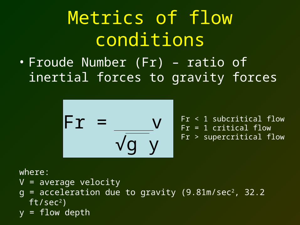
Metrics of flow conditions
• Froude Number (Fr) – ratio of inertial forces to gravity forces
Fr = v √g y
where:V = average velocityg = acceleration due to gravity (9.81m/sec2, 32.2 ft/sec2)y = flow depth
Fr < 1 subcritical flowFr = 1 critical flowFr > supercritical flow
Nash Stream at Whitcomb Peak. Image Source: Cohostrail.org
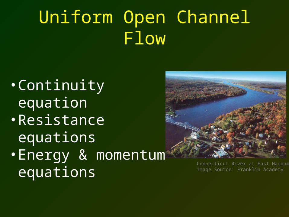
Uniform Open Channel Flow
• Continuity equation• Resistance equations • Energy & momentum
equations
Connecticut River at East Haddam. Image Source: Franklin Academy

Continuity
Inflow – Outflow = Change in Storage
Inflow
1 2
A
A’
3
Section AA’
Outflow
3
Image source: Andy Ward
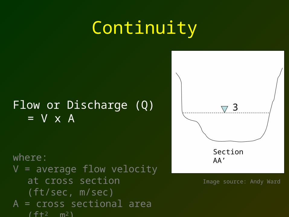
Continuity
Flow or Discharge (Q) = V x A
where: V = average flow velocity at cross
section (ft/sec, m/sec)A = cross sectional area (ft2, m2)
Section AA’
3
Image source: Andy Ward

velocity profile in a river
Depth-averaged velocity is above the bed at about 0.4 times the depth
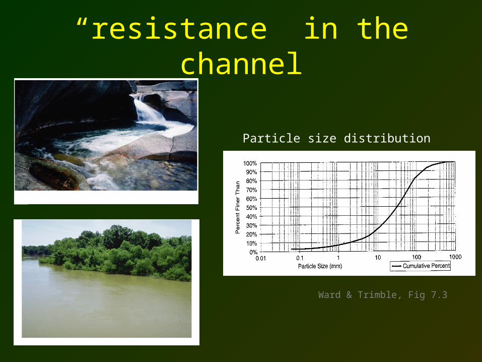
“resistance” in the channel
Particle size distribution
Ward & Trimble, Fig 7.3
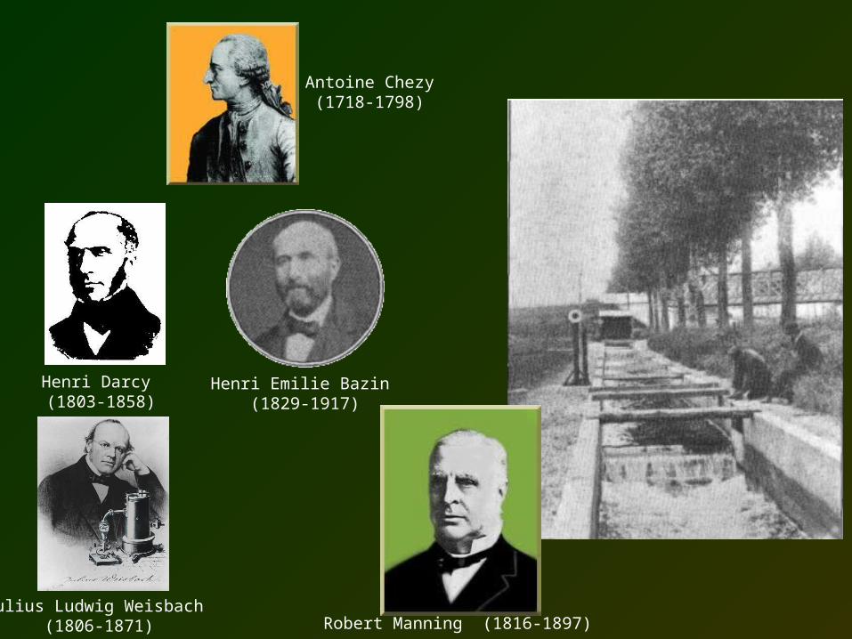
Henri Emilie Bazin (1829-1917)
Henri Darcy (1803-1858)
Julius Ludwig Weisbach (1806-1871) Robert Manning (1816-1897)
Antoine Chezy(1718-1798)
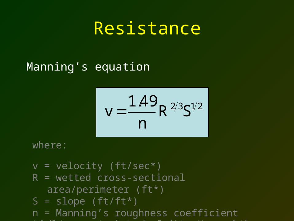
Resistance
Manning’s equation
2132 SRn
49.1v
where:
v = velocity (ft/sec*)R = wetted cross-sectional area/perimeter (ft*)S = slope (ft/ft*)n = Manning’s roughness coefficient* 1.49 is conversion factor for English units, use 1 if v, R, and S are in SI units
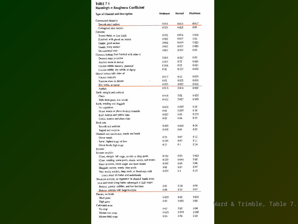
Ward & Trimble, Table 7.1
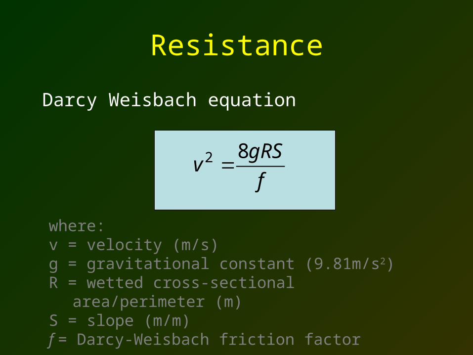
Resistance
Darcy Weisbach equation
where: v = velocity (m/s)g = gravitational constant (9.81m/s2)R = wetted cross-sectional area/perimeter (m)S = slope (m/m)f = Darcy-Weisbach friction factor
f
gRSv
82
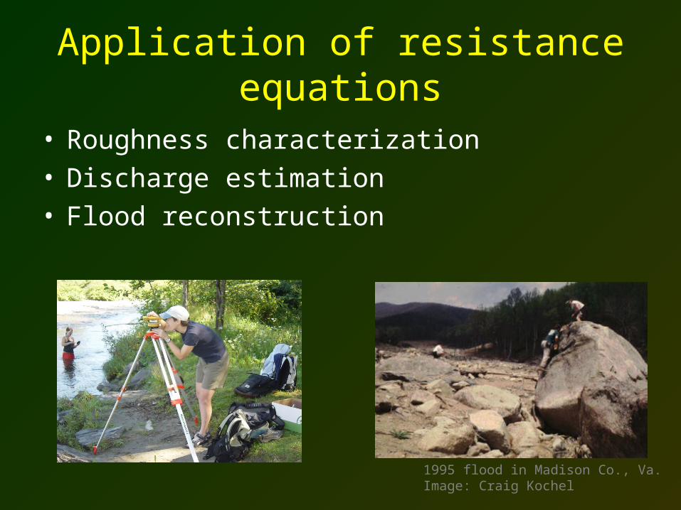
Application of resistance equations
• Roughness characterization• Discharge estimation• Flood reconstruction
1995 flood in Madison Co., Va.Image: Craig Kochel
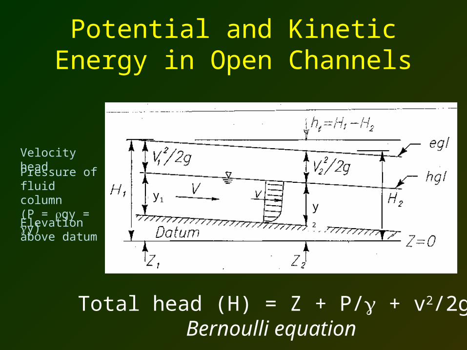
Potential and Kinetic Energy in Open Channels
Total head (H) = Z + P/ + v2/2gBernoulli equation
Elevation above datum
Pressure of fluid column(P = gy = y)
Velocity head
y1y2
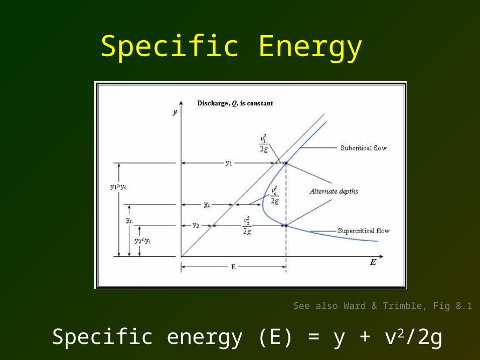
Specific Energy
See also Ward & Trimble, Fig 8.1
Specific energy (E) = y + v2/2g
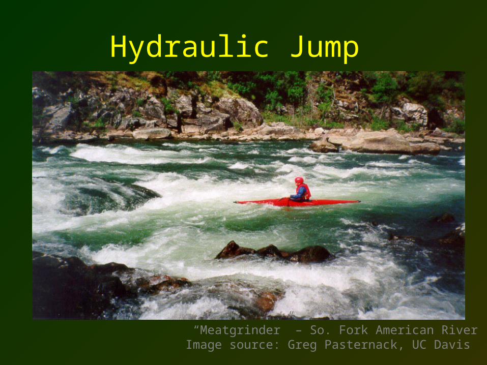
“Meatgrinder” – So. Fork American RiverImage source: Greg Pasternack, UC Davis
Hydraulic Jump


