98
O PEN DYNAMICS E NGINE V 0.5 U SER G UIDE Russell Smith THURSDAY 23 FEBRUARY , 2006 THIS DOCUMENT IS COPYRIGHT c 2001-2004 RUSSELL SMITH.
OPEN DYNAMICS ENGINEV0.5 USERGUIDE
Russell Smith
THURSDAY 23 FEBRUARY, 2006
THIS DOCUMENT ISCOPYRIGHT c© 2001-2004 RUSSELL SMITH .


Contents
Contents iii
1 Introduction 11.1 Features. . . . . . . . . . . . . . . . . . . . . . . . . . . . . . . . . . . . . . . . . . . . . 11.2 ODE’s License . . . . . . . . . . . . . . . . . . . . . . . . . . . . . . . . . . . . . . . . . 21.3 The ODE Community. . . . . . . . . . . . . . . . . . . . . . . . . . . . . . . . . . . . . . 2
2 How to Install and Use ODE 32.1 Installing ODE . . . . . . . . . . . . . . . . . . . . . . . . . . . . . . . . . . . . . . . . . 3
2.1.1 Building and Running ODE Tests on MacOS X. . . . . . . . . . . . . . . . . . . . 32.2 Using ODE . . . . . . . . . . . . . . . . . . . . . . . . . . . . . . . . . . . . . . . . . . . 4
3 Concepts 53.1 Background. . . . . . . . . . . . . . . . . . . . . . . . . . . . . . . . . . . . . . . . . . . 53.2 Rigid bodies. . . . . . . . . . . . . . . . . . . . . . . . . . . . . . . . . . . . . . . . . . . 5
3.2.1 Islands and Disabled Bodies. . . . . . . . . . . . . . . . . . . . . . . . . . . . . . 63.3 Integration. . . . . . . . . . . . . . . . . . . . . . . . . . . . . . . . . . . . . . . . . . . . 63.4 Force accumulators. . . . . . . . . . . . . . . . . . . . . . . . . . . . . . . . . . . . . . . 63.5 Joints and constraints. . . . . . . . . . . . . . . . . . . . . . . . . . . . . . . . . . . . . . 73.6 Joint groups. . . . . . . . . . . . . . . . . . . . . . . . . . . . . . . . . . . . . . . . . . . 73.7 Joint error and the error reduction parameter (ERP). . . . . . . . . . . . . . . . . . . . . . 73.8 Soft constraint and constraint force mixing (CFM). . . . . . . . . . . . . . . . . . . . . . . 8
3.8.1 Constraint Force Mixing (CFM). . . . . . . . . . . . . . . . . . . . . . . . . . . . 93.8.2 How To Use ERP and CFM. . . . . . . . . . . . . . . . . . . . . . . . . . . . . . 9
3.9 Collision handling. . . . . . . . . . . . . . . . . . . . . . . . . . . . . . . . . . . . . . . .103.10 Typical simulation code. . . . . . . . . . . . . . . . . . . . . . . . . . . . . . . . . . . . .103.11 Physics model. . . . . . . . . . . . . . . . . . . . . . . . . . . . . . . . . . . . . . . . . .11
3.11.1 Friction Approximation . . . . . . . . . . . . . . . . . . . . . . . . . . . . . . . .11
4 Data Types and Conventions 134.1 The basic data types. . . . . . . . . . . . . . . . . . . . . . . . . . . . . . . . . . . . . . .134.2 Objects and IDs. . . . . . . . . . . . . . . . . . . . . . . . . . . . . . . . . . . . . . . . .134.3 Argument conventions. . . . . . . . . . . . . . . . . . . . . . . . . . . . . . . . . . . . .134.4 C versus C++. . . . . . . . . . . . . . . . . . . . . . . . . . . . . . . . . . . . . . . . . .144.5 Debugging. . . . . . . . . . . . . . . . . . . . . . . . . . . . . . . . . . . . . . . . . . . .14
iii
5 World 155.1 Stepping Functions. . . . . . . . . . . . . . . . . . . . . . . . . . . . . . . . . . . . . . .175.2 Contact Parameters. . . . . . . . . . . . . . . . . . . . . . . . . . . . . . . . . . . . . . .17
6 Rigid Body Functions 196.1 Creating and Destroying Bodies. . . . . . . . . . . . . . . . . . . . . . . . . . . . . . . .196.2 Position and orientation. . . . . . . . . . . . . . . . . . . . . . . . . . . . . . . . . . . . .196.3 Mass and force. . . . . . . . . . . . . . . . . . . . . . . . . . . . . . . . . . . . . . . . .206.4 Utility . . . . . . . . . . . . . . . . . . . . . . . . . . . . . . . . . . . . . . . . . . . . . .216.5 Automatic Enabling and Disabling. . . . . . . . . . . . . . . . . . . . . . . . . . . . . . .216.6 Miscellaneous Body Functions. . . . . . . . . . . . . . . . . . . . . . . . . . . . . . . . .23
7 Joint Types and Joint Functions 257.1 Creating and Destroying Joints. . . . . . . . . . . . . . . . . . . . . . . . . . . . . . . . .257.2 Miscellaneous Joint Functions. . . . . . . . . . . . . . . . . . . . . . . . . . . . . . . . .267.3 Joint parameter setting functions. . . . . . . . . . . . . . . . . . . . . . . . . . . . . . . .27
7.3.1 Ball and Socket. . . . . . . . . . . . . . . . . . . . . . . . . . . . . . . . . . . . .277.3.2 Hinge . . . . . . . . . . . . . . . . . . . . . . . . . . . . . . . . . . . . . . . . . .287.3.3 Slider . . . . . . . . . . . . . . . . . . . . . . . . . . . . . . . . . . . . . . . . . .297.3.4 Universal . . . . . . . . . . . . . . . . . . . . . . . . . . . . . . . . . . . . . . . .307.3.5 Hinge-2. . . . . . . . . . . . . . . . . . . . . . . . . . . . . . . . . . . . . . . . .327.3.6 Fixed . . . . . . . . . . . . . . . . . . . . . . . . . . . . . . . . . . . . . . . . . .337.3.7 Contact. . . . . . . . . . . . . . . . . . . . . . . . . . . . . . . . . . . . . . . . .337.3.8 Angular Motor . . . . . . . . . . . . . . . . . . . . . . . . . . . . . . . . . . . . .36
7.4 General . . . . . . . . . . . . . . . . . . . . . . . . . . . . . . . . . . . . . . . . . . . . .387.5 Stop and motor parameters. . . . . . . . . . . . . . . . . . . . . . . . . . . . . . . . . . .38
7.5.1 Parameter Functions. . . . . . . . . . . . . . . . . . . . . . . . . . . . . . . . . .397.6 Setting Joint Torques/Forces Directly. . . . . . . . . . . . . . . . . . . . . . . . . . . . . .40
8 StepFast 438.1 When to use StepFast1. . . . . . . . . . . . . . . . . . . . . . . . . . . . . . . . . . . . .438.2 When NOT to use StepFast1. . . . . . . . . . . . . . . . . . . . . . . . . . . . . . . . . .458.3 How it works . . . . . . . . . . . . . . . . . . . . . . . . . . . . . . . . . . . . . . . . . .458.4 Experimental Utilities included with StepFast1. . . . . . . . . . . . . . . . . . . . . . . . 468.5 API . . . . . . . . . . . . . . . . . . . . . . . . . . . . . . . . . . . . . . . . . . . . . . .46
9 Support Functions 499.1 Rotation functions. . . . . . . . . . . . . . . . . . . . . . . . . . . . . . . . . . . . . . . .499.2 Mass functions . . . . . . . . . . . . . . . . . . . . . . . . . . . . . . . . . . . . . . . . .509.3 Math functions . . . . . . . . . . . . . . . . . . . . . . . . . . . . . . . . . . . . . . . . .529.4 Error and memory functions. . . . . . . . . . . . . . . . . . . . . . . . . . . . . . . . . .52
10 Collision Detection 5310.1 Contact points. . . . . . . . . . . . . . . . . . . . . . . . . . . . . . . . . . . . . . . . . .5310.2 Geoms. . . . . . . . . . . . . . . . . . . . . . . . . . . . . . . . . . . . . . . . . . . . . .5410.3 Spaces. . . . . . . . . . . . . . . . . . . . . . . . . . . . . . . . . . . . . . . . . . . . . .5410.4 General geom functions. . . . . . . . . . . . . . . . . . . . . . . . . . . . . . . . . . . . .5410.5 Collision detection . . . . . . . . . . . . . . . . . . . . . . . . . . . . . . . . . . . . . . .57
10.5.1 Category and Collide Bitfields. . . . . . . . . . . . . . . . . . . . . . . . . . . . .5810.5.2 Collision Detection Functions. . . . . . . . . . . . . . . . . . . . . . . . . . . . .59
10.6 Space functions. . . . . . . . . . . . . . . . . . . . . . . . . . . . . . . . . . . . . . . . .6010.7 Geometry Classes. . . . . . . . . . . . . . . . . . . . . . . . . . . . . . . . . . . . . . . .62
10.7.1 Sphere Class. . . . . . . . . . . . . . . . . . . . . . . . . . . . . . . . . . . . . .6210.7.2 Box Class. . . . . . . . . . . . . . . . . . . . . . . . . . . . . . . . . . . . . . . .6310.7.3 Plane Class. . . . . . . . . . . . . . . . . . . . . . . . . . . . . . . . . . . . . . .6310.7.4 Capped Cylinder Class. . . . . . . . . . . . . . . . . . . . . . . . . . . . . . . . .6410.7.5 Ray Class. . . . . . . . . . . . . . . . . . . . . . . . . . . . . . . . . . . . . . . .6510.7.6 Triangle Mesh Class. . . . . . . . . . . . . . . . . . . . . . . . . . . . . . . . . .6610.7.7 Geometry Transform Class. . . . . . . . . . . . . . . . . . . . . . . . . . . . . . .69
10.8 User defined classes. . . . . . . . . . . . . . . . . . . . . . . . . . . . . . . . . . . . . . .7010.9 Composite objects. . . . . . . . . . . . . . . . . . . . . . . . . . . . . . . . . . . . . . . .7210.10Utility functions. . . . . . . . . . . . . . . . . . . . . . . . . . . . . . . . . . . . . . . . .7310.11Implementation notes. . . . . . . . . . . . . . . . . . . . . . . . . . . . . . . . . . . . . .73
10.11.1 Large Environments. . . . . . . . . . . . . . . . . . . . . . . . . . . . . . . . . .7310.11.2 Using a Different Collision Library. . . . . . . . . . . . . . . . . . . . . . . . . . 73
11 How To Make Good Simulations 7511.1 Integrator accuracy and stability. . . . . . . . . . . . . . . . . . . . . . . . . . . . . . . .7511.2 Behavior may depend on step size. . . . . . . . . . . . . . . . . . . . . . . . . . . . . . .7511.3 Making things go faster. . . . . . . . . . . . . . . . . . . . . . . . . . . . . . . . . . . . .7511.4 Making things stable. . . . . . . . . . . . . . . . . . . . . . . . . . . . . . . . . . . . . .7611.5 Using constraint force mixing (CFM). . . . . . . . . . . . . . . . . . . . . . . . . . . . .7611.6 Avoiding singularities. . . . . . . . . . . . . . . . . . . . . . . . . . . . . . . . . . . . . .7711.7 Other stuff. . . . . . . . . . . . . . . . . . . . . . . . . . . . . . . . . . . . . . . . . . . .77
12 FAQ 7912.1 How do I connect a body to the static environment with a joint?. . . . . . . . . . . . . . . . 7912.2 Does ODE need or use graphics library X ?. . . . . . . . . . . . . . . . . . . . . . . . . . 7912.3 Why do my rigid bodies bounce or penetrate on collision? My restitution is zero!. . . . . . 7912.4 How can an immovable body be created?. . . . . . . . . . . . . . . . . . . . . . . . . . . 8012.5 Why would you ever want to set ERP less than one?. . . . . . . . . . . . . . . . . . . . . . 8012.6 Is it advisable to set body velocities directly, instead of applying a force or torque?. . . . . 8012.7 Why, when I set a body’s velocity directly, does it come up to speed slower when joined to
other bodies? . . . . . . . . . . . . . . . . . . . . . . . . . . . . . . . . . . . . . . . . . .8012.8 Should I scale my units to be around 1.0 ?. . . . . . . . . . . . . . . . . . . . . . . . . . . 8112.9 I’ve made a car, but the wheels don’t stay on properly!. . . . . . . . . . . . . . . . . . . . 8112.10How do I make “one way” collision interaction. . . . . . . . . . . . . . . . . . . . . . . . 8112.11The Windows version of ODE crashes with large systems. . . . . . . . . . . . . . . . . . . 8112.12My simple rotating bodies are unstable!. . . . . . . . . . . . . . . . . . . . . . . . . . . .8212.13My rolling bodies (e.g. wheels) sometimes get stuck between geoms. . . . . . . . . . . . . 82
12.13.1 The Problem. . . . . . . . . . . . . . . . . . . . . . . . . . . . . . . . . . . . . .8312.13.2 The Solution. . . . . . . . . . . . . . . . . . . . . . . . . . . . . . . . . . . . . .83
13 Known Issues 85

vi
14 ODE Internals 8714.1 Matrix storage conventions. . . . . . . . . . . . . . . . . . . . . . . . . . . . . . . . . . .8714.2 Internals FAQ. . . . . . . . . . . . . . . . . . . . . . . . . . . . . . . . . . . . . . . . . .88
14.2.1 Why do some structures have adx prefix and some have ad prefix? . . . . . . . . . 8814.2.2 Returned Vectors. . . . . . . . . . . . . . . . . . . . . . . . . . . . . . . . . . . .88
Index 89

Chapter 1
Introduction
The Open Dynamics Engine (ODE) is a free, industrial quality library for simulating articulated rigid bodydynamics. For example, it is good for simulating ground vehicles, legged creatures, and moving objectsin VR environments. It is fast, flexible and robust, and it has built-in collision detection. ODE is beingdeveloped byRussell Smith1 with help from severalcontributors2.
If “rigid body simulation” does not make much sense to you, check outWhat is a Physics SDK?3.This is the user guide for ODE version 0.5. Despite the low version number, ODE is reasonably mature
and stable.
1.1 Features
ODE is good for simulatingarticulatedrigid body structures. An articulated structure is created when rigidbodies of various shapes are connected together with joints of various kinds. Examples are ground vehicles(where the wheels are connected to the chassis), legged creatures (where the legs are connected to the body),or stacks of objects.
ODE is designed to be used in interactive or real-time simulation. It is particularly good for simulatingmoving objects in changeable virtual reality environments. This is because it is fast, robust and stable, andthe user has complete freedom to change the structure of the system even while the simulation is running.
ODE uses a highly stable integrator, so that the simulation errors should not grow out of control. Thephysical meaning of this is that the simulated system should not ”explode” for no reason (believe me, thishappens a lot with other simulators if you are not careful). ODE emphasizes speed and stability over physicalaccuracy.
ODE hashard contacts. This means that a special non-penetration constraint is used whenever twobodies collide. The alternative, used in many other simulators, is to use virtual springs to represent contacts.This is difficult to do right and extremely error-prone.
ODE has a built-in collision detection system. However you can ignore it and do your own collisiondetection if you want to. The current collision primitives are sphere, box, capped cylinder, plane, ray, andtriangular mesh - more collision objects will come later. ODE’s collision system provides fast identificationof potentially intersecting objects, through the concept of “spaces”.
Here are the features:
• Rigid bodies with arbitrary mass distribution.
1http://www.q12.org2http://opende.sourceforge.net/community.html3http://opende.sourceforge.net/slides/slides.html
1
2 CHAPTER 1. INTRODUCTION
• Joint types: ball-and-socket, hinge, slider (prismatic), hinge-2, fixed, angular motor, universal.
• Collision primitives: sphere, box, capped cylinder, plane, ray, and triangular mesh.
• Collision spaces: Quad tree, hash space, and simple.
• Simulation method: The equations of motion are derived from a Lagrange multiplier velocity basedmodel due to Trinkle/Stewart and Anitescu/Potra.
• A first order integrator is being used. It’s fast, but not accurate enough for quantitative engineeringyet. Higher order integrators will come later.
• Choice of time stepping methods: either the standard “big matrix” method or the newer iterativeQuickStep method can be used.
• Contact and friction model: This is based on the Dantzig LCP solver described by Baraff, althoughODE implements a faster approximation to the Coloumb friction model.
• Has a native C interface (even though ODE is mostly written in C++).
• Has a C++ interface built on top of the C one.
• Many unit tests, and more being written all the time.
• Platform specific optimizations.
• Other stuff I forgot to mention...
1.2 ODE’s License
ODE is Copyright c© 2001-2004 Russell L. Smith. All rights reserved.This library is free software; you can redistribute it and/or modify it under the terms of EITHER:
1. TheGNU Lesser General Public License4 as published by the Free Software Foundation; either ver-sion 2.1 of the License, or (at your option) any later version. The text of the GNU Lesser GeneralPublic License is included with this library in the fileLICENSE.TXT .
2. TheBSD-style license5 that is included with this library in the fileLICENSE-BSD.TXT .
This library is distributed in the hope that it will be useful, butWITHOUT ANY WARRANTY; without eventhe implied warranty of MERCHANTABILITY or FITNESS FOR A PARTICULAR PURPOSE. See thefilesLICENSE.TXT andLICENSE-BSD.TXT for more details.
1.3 The ODE Community
Do you have questions or comments about ODE? Think you can help? Pleasewrite to the ODE mailinglist6.
4http://www.opensource.org/licenses/lgpl-license.html5http://opende.sourceforge.net/ode-license.html6http://q12.org/mailman/listinfo/ode

Chapter 2
How to Install and Use ODE
2.1 Installing ODE
Step 1: Unpack the ODE archive.Steps 2-4 (alternate):If you’re on windows and using MSVC, you can use the workspace and project
files in the VC6 subdirectory of the distribution.Step 2: Get the GNUmake tool. Many Unix platforms come with this, although sometimes it is called
gmake. A version of GNU make for windows is availablehere1.Step 3: Edit the settings in the fileconfig/user-settings . The list of supported platforms is
given in that file.Step 4:Run GNUmake to configure and build ODE and the graphical test programs. The configuration
process creates the fileinclude/ode/config.h .Step 5: To install the ODE library onto your system you should copy thelib/ andinclude/ direc-
tories to a suitable place, e.g. on Unix:
• include/ode/ --> /usr/local/include/ode/
• lib/libode.a --> /usr/local/lib/libode.a
2.1.1 Building and Running ODE Tests on MacOS X
ODE uses XWindows and OpenGL to render the scene being simulated. In order to build the example youwill need to install Apple X11 server and the X11SDK (as well as the normal developer tools).
These are available from Apple. As of writing this can be found at:http://www.apple.com/macosx/x112.NOTE: there is a tiny link at the bottom right of the page for the SDK
Once the software is installed follow the normal build instructions.Since ODE uses X11 you need to run the X11 server (which you should have installed, it’s in the
Applications Folder).If you run the test app in the XTerm that the X11 server opens by default then they should run fine.
If however you run them from a MacOS X Terminal then you need to define the environment variableDISPLAY. If DISPLAY is not defined then you will get a message saying: ”cannot open X11 display”.
For example to run the boxstack test you would type
1http://q12.org/ode/bin/make.exe2http://www.apple.com/macosx/x11
3
4 CHAPTER 2. HOW TO INSTALL AND USE ODE
cd ode/testDISPLAY=:0.0 ./test_boxstack.exe
You can define this environment variable in your shell startup scripts (for example in∼/.bashrc if you areusing bash)
2.2 Using ODE
The best way to understand how to use ODE is to look at the test/example programs that come with it. Notethe following things:
• Source files that use ODE only need to include a single header file:
#include <ode/ode.h>
Theode directory in this statement is actually theinclude/ode directory of the ODE distribution.This header file will include others in theode directory, so you need to set the include path of yourcompiler, e.g. in linux
gcc -c -I /home/username/ode/include myprogram.cpp
• When ODE is used with thedWorldStep()function, heavy use is made of the stack for storing tem-porary values. For very large systems several megabytes of stack can be used. If you experienceunexplained out-of-memory errors or data corruption, especially on Windows, try increasing the stacksize, or switching todWorldQuickStep().
Chapter 3
Concepts
3.1 Background
[Here is where I will write some background information about rigid body dynamics and simulation. But inthe meantime, please refer to Baraff’s excellentSIGGRAPH tutorial1].
3.2 Rigid bodies
A rigid body has various properties from the point of view of the simulation. Some properties change overtime:
• Position vector (x,y,z) of the body’s point of reference. Currently the point of reference must corre-spond to the body’s center of mass.
• Linear velocity of the point of reference, a vector (vx,vy,vz).
• Orientation of a body, represented by a quaternion (qs,qx,qy,qz) or a 3x3 rotation matrix.
• Angular velocity vector (wx,wy,wz) which describes how the orientation changes over time.
Other body properties are usually constant over time:
• Mass of the body.
• Position of the center of mass with respect to the point of reference. In the current implementation thecenter of mass and the point of reference must coincide.
• Inertia matrix. This is a 3x3 matrix that describes how the body’s mass is distributed around the centerof mass.
Conceptually each body has an x-y-z coordinate frame embedded in it, that moves and rotates with the body,as shown inFigure 3.1.
The origin of this coordinate frame is the body’s point of reference. Some values in ODE (vectors,matrices etc) are relative to the body coordinate frame, and others are relative to the global coordinateframe.
Note that theshapeof a rigid body is not a dynamical property (except insofar as it influences the variousmass properties). It is onlycollision detectionthat cares about the detailed shape of the body.
1http://www.cs.cmu.edu/ ∼baraff/sigcourse/index.html
5

6 CHAPTER 3. CONCEPTS
Figure 3.1: The body coordinate frame.
3.2.1 Islands and Disabled Bodies
Bodies are connected to each other with joints. An “island” of bodies is a group that can not be pulled apart- in other words each body is connected somehow to every other body in the island.
Each island in the world is treated separately when the simulation step is taken. This is useful to know:if there areN similar islands in the simulation then the step computation time will beO(N).
Each body can be enabled or disabled. Disabled bodies are effectively “turned off” and are not updatedduring a simulation step. Disabling bodies is an effective way to save computation time when it is knownthat the bodies are motionless or otherwise irrelevant to the simulation.
If there are any enabled bodies in an island then every body in the island will be enabled at the nextsimulation step. Thus to effectively disable an island of bodies,everybody in the island must be disabled.If a disabled island is touched by another enabled body then the entire island will be enabled, as a contactjoint will join the enabled body to the island.
3.3 Integration
The process of simulating the rigid body system through time is called integration. Each integration stepadvances the current time by a given step size, adjusting the state of all the rigid bodies for the new timevalue. There are two main issues to consider when working with any integrator:
• How accurate is it? That is, how closely does the behavior of the simulated system match what wouldhappen in real life?
• How stable is it? That is, will calculation errors ever cause completely non-physical behavior of thesimulated system? (e.g. causing the system to ”explode” for no reason).
ODE’s current integrator is very stable, but not particularly accurate unless the step size is small. Formost uses of ODE this is not a problem – ODE’s behavior still looks perfectly physical in almost all cases.However ODE should not be used for quantitative engineering until this accuracy issue has been addressedin a future release.
3.4 Force accumulators
Between each integrator step the user can call functions to apply forces to the rigid body. These forces areadded to ”force accumulators” in the rigid body object. When the next integrator step happens, the sum of

3.5. JOINTS AND CONSTRAINTS 7
Figure 3.2: Three different constraint types.
all the applied forces will be used to push the body around. The forces accumulators are set to zero aftereach integrator step.
3.5 Joints and constraints
In real life a joint is something like a hinge, that is used to connect two objects. In ODE a joint is verysimilar: It is a relationship that is enforced between two bodies so that they can only have certain positionsand orientations relative to each other. This relationship is called aconstraint– the wordsjoint andconstraintare often used interchangeably.Figure 3.2shows three different constraint types.
The first is a ball and socket joint that constraints the “ball” of one body to be in the same location asthe “socket” of another body. The second is a hinge joint that constraints the two parts of the hinge to be inthe same location and to line up along the hinge axle. The third is a slider joint that constraints the “piston”and “socket” to line up, and additionally constraints the two bodies to have the same orientation.
Each time the integrator takes a step all the joints are allowed to applyconstraint forcesto the bodiesthey affect. These forces are calculated such that the bodies move in such a way to preserve all the jointrelationships.
Each joint has a number of parameters controlling its geometry. An example is the position of the ball-and-socket point for a ball-and-socket joint. The functions to set joint parameters all takeglobalcoordinates,not body-relative coordinates. A consequence of this is that the rigid bodies that a joint connects must bepositioned correctlybeforethe joint is attached.
3.6 Joint groups
A joint group is a special container that holds joints in a world. Joints can be added to a group, and thenwhen those joints are no longer needed the entire group of joints can be very quickly destroyed with onefunction call. However, individual joints in a group can not be destroyed before the entire group is emptied.
This is most useful with contact joints, which are added and remove from the world in groups every timestep.
3.7 Joint error and the error reduction parameter (ERP)
When a joint attaches two bodies, those bodies are required to have certain positions and orientations relativeto each other. However, it is possible for the bodies to be in positions where the joint constraints are not met.This “joint error” can happen in two ways:
1. If the user sets the position/orientation of one body without correctly setting the position/orientationof the other body.
8 CHAPTER 3. CONCEPTS
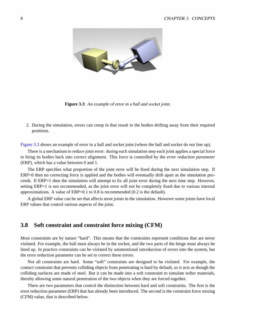
Figure 3.3: An example of error in a ball and socket joint.
2. During the simulation, errors can creep in that result in the bodies drifting away from their requiredpositions.
Figure 3.3shows an example of error in a ball and socket joint (where the ball and socket do not line up).
There is a mechanism to reduce joint error: during each simulation step each joint applies a special forceto bring its bodies back into correct alignment. This force is controlled by theerror reduction parameter(ERP), which has a value between 0 and 1.
The ERP specifies what proportion of the joint error will be fixed during the next simulation step. IfERP=0 then no correcting force is applied and the bodies will eventually drift apart as the simulation pro-ceeds. If ERP=1 then the simulation will attempt to fix all joint error during the next time step. However,setting ERP=1 is not recommended, as the joint error will not be completely fixed due to various internalapproximations. A value of ERP=0.1 to 0.8 is recommended (0.2 is the default).
A global ERP value can be set that affects most joints in the simulation. However some joints have localERP values that control various aspects of the joint.
3.8 Soft constraint and constraint force mixing (CFM)
Most constraints are by nature “hard”. This means that the constraints represent conditions that are neverviolated. For example, the ball must always be in the socket, and the two parts of the hinge must always belined up. In practice constraints can be violated by unintentional introduction of errors into the system, butthe error reduction parameter can be set to correct these errors.
Not all constraints are hard. Some “soft” constraints are designed to be violated. For example, thecontact constraint that prevents colliding objects from penetrating is hard by default, so it acts as though thecolliding surfaces are made of steel. But it can be made into a soft constraint to simulate softer materials,thereby allowing some natural penetration of the two objects when they are forced together.
There are two parameters that control the distinction between hard and soft constraints. The first is theerror reduction parameter (ERP) that has already been introduced. The second is the constraint force mixing(CFM) value, that is described below.
3.8. SOFT CONSTRAINT AND CONSTRAINT FORCE MIXING (CFM) 9
3.8.1 Constraint Force Mixing (CFM)
What follows is a somewhat technical description of the meaning of CFM. If you just want to know how itis used in practice then skip to the next section.
Traditionally the constraint equation for every joint has the form
J ∗ v = c (3.1)
wherev is a velocity vector for the bodies involved,J is a “Jacobian” matrix with one row for everydegree of freedom the joint removes from the system, andc is a right hand side vector. At the next time step,a vectorlambda is calculated (of the same size asc) such that the forces applied to the bodies to preservethe joint constraint are
force = JT ∗ λ (3.2)
ODE adds a new twist. ODE’s constraint equation has the form
J ∗ v = c + CFM ∗ λ (3.3)
whereCFM is a square diagonal matrix.CFM mixes the resulting constraint force in with the con-straint that produces it. A nonzero (positive) value ofCFM allows the original constraint equation tobe violated by an amount proportional to CFM times the restoring forceλ that is needed to enforce theconstraint. Solving forλ gives
(JM−1JT + CFM/h)λ = c/h (3.4)
ThusCFM simply adds to the diagonal of the original system matrix. Using a positive value ofCFMhas the additional benefit of taking the system away from any singularity and thus improving the factorizeraccuracy.
3.8.2 How To Use ERP and CFM
ERP and CFM can be independently set in many joints. They can be set in contact joints, in joint limits andvarious other places, to control the spongyness and springyness of the joint (or joint limit).
If CFM is set to zero, the constraint will be hard. If CFM is set to a positive value, it will be possible toviolate the constraint by “pushing on it” (for example, for contact constraints by forcing the two contactingobjects together). In other words the constraint will be soft, and the softness will increase as CFM increases.What is actually happening here is that the constraint is allowed to be violated by an amount proportional toCFM times the restoring force that is needed to enforce the constraint. Note that setting CFM to a negativevalue can have undesirable bad effects, such as instability. Don’t do it.
By adjusting the values of ERP and CFM, you can achieve various effects. For example you can simulatespringy constraints, where the two bodies oscillate as though connected by springs. Or you can simulatemore spongy constraints, without the oscillation. In fact, ERP and CFM can be selected to have the sameeffect as any desired spring and damper constants. If you have a spring constantkp and damping constantkd, then the corresponding ODE constants are:

10 CHAPTER 3. CONCEPTS
ERP = hkp/(hkp + kd) (3.5)
CFM = 1/(hkp + kd) (3.6)
whereh is the stepsize. These values will give the same effect as a spring-and-damper system simulatedwith implicit first order integration.
Increasing CFM, especially the global CFM, can reduce the numerical errors in the simulation. If thesystem is near-singular, then this can markedly increase stability. In fact, if the system is mis-behaving, oneof the first things to try is to increase the global CFM.
3.9 Collision handling
[There is a lot that needs to be written about collision handling.]Collisions between bodies or between bodies and the static environment are handled as follows:
1. Before each simulation step, the user calls collision detection functions to determine what is touchingwhat. These functions return a list of contact points. Each contact point specifies a position in space,a surface normal vector, and a penetration depth.
2. A special contact joint is created for each contact point. The contact joint is given extra informationabout the contact, for example the friction present at the contact surface, how bouncy or soft it is, andvarious other properties.
3. The contact joints are put in a joint ”group”, which allows them to be added to and removed from thesystem very quickly. The simulation speed goes down as the number of contacts goes up, so variousstrategies can be used to limit the number of contact points.
4. A simulation step is taken.
5. All contact joints are removed from the system.
Note that the built-in collision functions do not have to be used - other collision detection libraries can beused as long as they provide the right kinds of contact point information.
3.10 Typical simulation code
A typical simulation will proceed like this:
1. Create a dynamics world.
2. Create bodies in the dynamics world.
3. Set the state (position etc) of all bodies.
4. Create joints in the dynamics world.
5. Attach the joints to the bodies.
6. Set the parameters of all joints.
3.11. PHYSICS MODEL 11
7. Create a collision world and collision geometry objects, as necessary.
8. Create a joint group to hold the contact joints.
9. Loop:
(a) Apply forces to the bodies as necessary.
(b) Adjust the joint parameters as necessary.
(c) Call collision detection.
(d) Create a contact joint for every collision point, and put it in the contact joint group.
(e) Take a simulation step.
(f) Remove all joints in the contact joint group.
10. Destroy the dynamics and collision worlds.
3.11 Physics model
The various methods and approximations that are used in ODE are discussed here.
3.11.1 Friction Approximation
[We really need more pictures here.]The Coulomb friction model is a simple, but effective way to model friction at contact points. It is a
simple relationship between the normal and tangential forces present at a contact point (see the contact jointsection for a description of these forces). The rule is:
|fT | <= µ ∗ |fN | (3.7)
wherefN andfT are the normal and tangential force vectors respectively, andµ is the friction coefficient(typically a number around 1.0). This equation defines a ”friction cone” - imagine a cone withfN as theaxis and the contact point as the vertex. If the total friction force vector is within the cone then the contactis in ”sticking mode”, and the friction force is enough to prevent the contacting surfaces from moving withrespect to each other. If the force vector is on the surface of the cone then the contact is in ”sliding mode”,and the friction force is typically not large enough to prevent the contacting surfaces from sliding. Theparameterµ thus specifies the maximum ratio of tangential to normal force.
ODE’s friction models are approximations to the friction cone, for reasons of efficiency. There arecurrently two approximations to chose from:
1. The meaning ofµ is changed so that it specifies the maximum friction (tangential) force that can bepresent at a contact, in either of the tangential friction directions. This is rather non physical becauseit is independent of the normal force, but it can be useful and it is the computationally cheapest option.Note that in this caseµ is a force limit an must be chosen appropriate to the simulation.
2. The friction cone is approximated by a friction pyramid aligned with the first and second frictiondirections [I really need a picture here]. A further approximation is made: first ODE computes thenormal forces assuming that all the contacts are frictionless. Then it computes the maximum limitsfm for the friction (tangential) forces from
12 CHAPTER 3. CONCEPTS
fm = µ ∗ |fN | (3.8)
and then proceeds to solve for the entire system with these fixed limits (in a manner similar to ap-proximation 1 above). This differs from a true friction pyramid in that the ”effective”µ is not quitefixed. This approximation is easier to use asµ is a unit-less ratio the same as the normal Coloumbfriction coefficient, and thus can be set to a constant value around 1.0 without regard for the specificsimulation.

Chapter 4
Data Types and Conventions
4.1 The basic data types
The ODE library can be built to use either single or double precision floating point numbers. Single precisionis faster and uses less memory, but the simulation will have more numerical error that can result in visibleproblems. You will get less accuracy and stability with single precision.
[must describe what factors influence accuracy and stability].The floating point data type isdReal . Other commonly used types aredVector3 , dVector4 ,
dMatrix3 , dMatrix4 , dQuaternion .
4.2 Objects and IDs
There are various kinds of object that can be created:
• dWorld - a dynamics world.
• dSpace - a collision space.
• dBody - a rigid body.
• dGeom - geometry (for collision).
• dJoint - a joint
• dJointGroup - a group of joints.
Functions that deal with these objects take and return object IDs. The object ID types aredWorldID ,dBodyID , etc.
4.3 Argument conventions
All 3-vectors (x,y,z) supplied to “set” functions are given as individual x,y,z arguments.All 3-vector result arguments to get() function are pointers to arrays ofdReal .Larger vectors are always supplied and returned as pointers to arrays ofdReal .All coordinates are in the global frame except where otherwise specified.
13

14 CHAPTER 4. DATA TYPES AND CONVENTIONS
4.4 C versus C++
The ODE library is written in C++, but its public interface is made of simple C functions, not classes. Whyis this?
• Using a C interface only is simpler - the features of C++ features do not help much for ODE.
• It prevents C++ mangling and runtime-support problems across multiple compilers.
• The user doesn’t have to be familiar with C++ quirks to use ODE.
4.5 Debugging
The ODE library can be compiled in ”debugging” or ”release” mode. Debugging mode is slower, butfunction arguments are checked and many run-time tests are done to ensure internal consistency. Releasemode is faster, but no checking is done.
Chapter 5
World
The world object is a container for rigid bodies and joints. Objects in different worlds can not interact, forexample rigid bodies from two different worlds can not collide.
All the objects in a world exist at the same point in time, thus one reason to use separate worlds is tosimulate systems at different rates.
Most applications will only need one world.
dWorldID dWorldCreate();
Create a new, empty world and return its ID number.
void dWorldDestroy (dWorldID);
Destroy a world and everything in it. This includes all bodies, and all joints that are not part of a jointgroup. Joints that are part of a joint group will be deactivated, and can be destroyed by calling, forexample,dJointGroupEmpty().
void dWorldSetGravity (dWorldID, dReal x, dReal y, dReal z);void dWorldGetGravity (dWorldID, dVector3 gravity);
Set and get the world’s global gravity vector. The units are m/s/s, so Earth’s gravity vector would be(0,0,-9.81), assuming that +z is up. The default is no gravity, i.e. (0,0,0).
void dWorldSetERP (dWorldID, dReal erp);dReal dWorldGetERP (dWorldID);
Set and get the global ERP value, that controls how much error correction is performed in each timestep. Typical values are in the range 0.1–0.8. The default is 0.2.
void dWorldSetCFM (dWorldID, dReal cfm);dReal dWorldGetCFM (dWorldID);
15

16 CHAPTER 5. WORLD
Set and get the global CFM (constraint force mixing) value. Typical values are in the range10−9 – 1.The default is10−5 if single precision is being used, or10−10 if double precision is being used.
void dWorldSetAutoDisableFlag (dWorldID, int do_auto_disable);int dWorldGetAutoDisableFlag (dWorldID);void dWorldSetAutoDisableLinearThreshold (dWorldID, dReal linear_threshold);dReal dWorldGetAutoDisableLinearThreshold (dWorldID);void dWorldSetAutoDisableAngularThreshold (dWorldID, dReal angular_threshold);dReal dWorldGetAutoDisableAngularThreshold (dWorldID);void dWorldSetAutoDisableSteps (dWorldID, int steps);int dWorldGetAutoDisableSteps (dWorldID);void dWorldSetAutoDisableTime (dWorldID, dReal time);dReal dWorldGetAutoDisableTime (dWorldID);
Set and get the default auto-disable parameters for newly created bodies. See section6.5for a descrip-tion of the auto-disable feature. The default parameters are:
• AutoDisableFlag = disabled
• AutoDisableLinearThreshold = 0.01
• AutoDisableAngularThreshold = 0.01
• AutoDisableSteps = 10
• AutoDisableTime = 0
void dWorldImpulseToForce (dWorldID, dReal stepsize,dReal ix, dReal iy, dReal iz, dVector3 force);
If you want to apply a linear or angular impulse to a rigid body, instead of a force or a torque, thenyou can use this function to convert the desired impulse into a force/torque vector before calling thedBodyAdd... function.
This function is given the desired impulse as (ix ,iy ,iz ) and puts the force vector inforce . Thecurrent algorithm simply scales the impulse by 1/stepsize , wherestepsize is the step size forthenextstep that will be taken.
This function is given adWorldID because, in the future, the force computation may depend onintegrator parameters that are set as properties of the world.
void dCloseODE();
This deallocates some extra memory used by ODE that can not be deallocated using the normal destroyfunctions, e.g.dWorldDestroy(). You can use this function at the end of your application to preventmemory leak checkers from complaining about ODE.

5.1. STEPPING FUNCTIONS 17
5.1 Stepping Functions
void dWorldStep (dWorldID, dReal stepsize);
Step the world. This uses a ”big matrix” method that takes time on the order ofm3 and memory on theorder ofm2, wherem is the total number of constraint rows.
For large systems this will use a lot of memory and can be very slow, but this is currently the mostaccurate method.
void dWorldQuickStep (dWorldID, dReal stepsize);
Step the world. This uses an iterative method that takes time on the order ofm ∗N and memory on theorder ofm, wherem is the total number of constraint rows andN is the number of iterations.
For large systems this is a lot faster thandWorldStep(), but it is less accurate.
QuickStep is great for stacks of objects especially when the auto-disable feature is used as well. How-ever, it has poor accuracy for near-singular systems. Near-singular systems can occur when usinghigh-friction contacts, motors, or certain articulated structures. For example, a robot with multiple legssitting on the ground may be near-singular.
There are ways to help overcome QuickStep’s inaccuracy problems:
• Increase CFM.
• Reduce the number of contacts in your system (e.g. use the minimum number of contacts for thefeet of a robot or creature).
• Don’t use excessive friction in the contacts.
• Use contact slip if appropriate
• Avoid kinematic loops (however, kinematic loops are inevitable in legged creatures).
• Don’t use excessive motor strength.
• Use force-based motors instead of velocity-based motors.
Increasing the number of QuickStep iterations may help a little bit, but it is not going to help much ifyour system is really near singular.
void dWorldSetQuickStepNumIterations (dWorldID, int num);int dWorldGetQuickStepNumIterations (dWorldID);
Set and get the number of iterations that the QuickStep method performs per step. More iterations willgive a more accurate solution, but will take longer to compute. The default is 20 iterations.
5.2 Contact Parameters
void dWorldSetContactMaxCorrectingVel (dWorldID, dReal vel);dReal dWorldGetContactMaxCorrectingVel (dWorldID);

18 CHAPTER 5. WORLD
Set and get the maximum correcting velocity that contacts are allowed to generate. The default valueis infinity (i.e. no limit). Reducing this value can help prevent ”popping” of deeply embedded objects.
void dWorldSetContactSurfaceLayer (dWorldID, dReal depth);dReal dWorldGetContactSurfaceLayer (dWorldID);
Set and get the depth of the surface layer around all geometry objects. Contacts are allowed to sink intothe surface layer up to the given depth before coming to rest. The default value is zero. Increasing thisto some small value (e.g. 0.001) can help prevent jittering problems due to contacts being repeatedlymade and broken.

Chapter 6
Rigid Body Functions
6.1 Creating and Destroying Bodies
dBodyID dBodyCreate (dWorldID);
Create a body in the given world with default mass parameters at position (0,0,0). Return its ID.
void dBodyDestroy (dBodyID);
Destroy a body. All joints that are attached to this body will be put into limbo (i.e. unattached and notaffecting the simulation, but they will NOT be deleted).
6.2 Position and orientation
void dBodySetPosition (dBodyID, dReal x, dReal y, dReal z);void dBodySetRotation (dBodyID, const dMatrix3 R);void dBodySetQuaternion (dBodyID, const dQuaternion q);void dBodySetLinearVel (dBodyID, dReal x, dReal y, dReal z);void dBodySetAngularVel (dBodyID, dReal x, dReal y, dReal z);const dReal * dBodyGetPosition (dBodyID);const dReal * dBodyGetRotation (dBodyID);const dReal * dBodyGetQuaternion (dBodyID);const dReal * dBodyGetLinearVel (dBodyID);const dReal * dBodyGetAngularVel (dBodyID);
These functions set and get the position, rotation, linear and angular velocity of the body. After settinga group of bodies, the outcome of the simulation is undefined if the new configuration is inconsistentwith the joints/constraints that are present. When getting, the returned values are pointers to internaldata structures, so the vectors are valid until any changes are made to the rigid body system structure.
Hmmm.dBodyGetRotation returns a 4x3 rotation matrix.
19

20 CHAPTER 6. RIGID BODY FUNCTIONS
6.3 Mass and force
void dBodySetMass (dBodyID, const dMass *mass);void dBodyGetMass (dBodyID, dMass *mass);
Set/get the mass of the body (see the mass functions).
void dBodyAddForce (dBodyID, dReal fx, dReal fy, dReal fz);void dBodyAddTorque (dBodyID, dReal fx, dReal fy, dReal fz);void dBodyAddRelForce (dBodyID, dReal fx, dReal fy, dReal fz);void dBodyAddRelTorque (dBodyID, dReal fx, dReal fy, dReal fz);void dBodyAddForceAtPos (dBodyID, dReal fx, dReal fy, dReal fz,
dReal px, dReal py, dReal pz);void dBodyAddForceAtRelPos (dBodyID, dReal fx, dReal fy, dReal fz,
dReal px, dReal py, dReal pz);void dBodyAddRelForceAtPos (dBodyID, dReal fx, dReal fy, dReal fz,
dReal px, dReal py, dReal pz);void dBodyAddRelForceAtRelPos (dBodyID, dReal fx, dReal fy, dReal fz,
dReal px, dReal py, dReal pz);
Add forces to bodies (absolute or relative coordinates). The forces are accumulated on to each body,and the accumulators are zeroed after each time step.
The ...RelForce and ...RelTorque functions take force vectors that are relative to the body’s ownframe of reference.
The ...ForceAtPos and ...ForceAtRelPos functions take an extra position vector (in global orbody-relative coordinates respectively) that specifies the point at which the force is applied. All otherfunctions apply the force at the center of mass.
const dReal * dBodyGetForce (dBodyID);const dReal * dBodyGetTorque (dBodyID);
Return the current accumulated force and torque vector. The returned pointers point to an array of 3dReal s. The returned values are pointers to internal data structures, so the vectors are only valid untilany changes are made to the rigid body system.
void dBodySetForce (dBodyID b, dReal x, dReal y, dReal z);void dBodySetTorque (dBodyID b, dReal x, dReal y, dReal z);
Set the body force and torque accumulation vectors. This is mostly useful to zero the force and torquefor deactivated bodies before they are reactivated, in the case where the force-adding functions werecalled on them while they were deactivated.
6.4. UTILITY 21
6.4 Utility
void dBodyGetRelPointPos (dBodyID, dReal px, dReal py, dReal pz,dVector3 result);
void dBodyGetRelPointVel (dBodyID, dReal px, dReal py, dReal pz,dVector3 result);
void dBodyGetPointVel (dBodyID, dReal px, dReal py, dReal pz,dVector3 result);
Utility functions that take a point on a body (px ,py ,pz ) and return that point’s position or velocityin global coordinates (inresult ). ThedBodyGetRelPointXXX functions are given the point inbody relative coordinates, and thedBodyGetPointVel function is given the point in global coordi-nates.
void dBodyGetPosRelPoint (dBodyID, dReal px, dReal py, dReal pz,dVector3 result);
This is the inverse ofdBodyGetRelPointPos(). It takes a point in global coordinates (x ,y ,z ) and returnsthe point’s position in body-relative coordinates (result ).
void dBodyVectorToWorld (dBodyID, dReal px, dReal py, dReal pz,dVector3 result);
void dBodyVectorFromWorld (dBodyID, dReal px, dReal py, dReal pz,dVector3 result);
Given a vector expressed in the body (or world) coordinate system (x ,y ,z ), rotate it to the world (orbody) coordinate system (result ).
6.5 Automatic Enabling and Disabling
Every body can be enabled or disabled. Enabled bodies participate in the simulation, while disabled bodiesare turned off and do not get updated during a simulation step. New bodies are always created in the enabledstate.
A disabled body that is connected through a joint to an enabled body will be automatically re-enabled atthe next simulation step.
Disabled bodies do not consume CPU time, therefore to speed up the simulation bodies should bedisabled when they come to rest. This can be done automatically with the auto-disable feature.
If a body has its auto-disable flag turned on, it will automatically disable itself when
1. It has been idle for a given number of simulation steps.
2. It has also been idle for a given amount of simulation time.
A body is considered to be idle when the magnitudes of both its linear velocity and angular velocity arebelow given thresholds.
Thus, every body has five auto-disable parameters: an enabled flag, a idle step count, an idle time, andlinear/angular velocity thresholds. Newly created bodies get these parameters from world.
The following functions set and get the enable/disable parameters of a body.

22 CHAPTER 6. RIGID BODY FUNCTIONS
void dBodyEnable (dBodyID);void dBodyDisable (dBodyID);
Manually enable and disable a body. Note that a disabled body that is connected through a joint to anenabled body will be automatically re-enabled at the next simulation step.
int dBodyIsEnabled (dBodyID);
Return 1 if a body is currently enabled or 0 if it is disabled.
void dBodySetAutoDisableFlag (dBodyID, int do_auto_disable);int dBodyGetAutoDisableFlag (dBodyID);
Set and get the auto-disable flag of a body. If thedo auto disable is nonzero the body will beautomatically disabled when it has been idle for long enough.
void dBodySetAutoDisableLinearThreshold (dBodyID, dReal linear_threshold);dReal dBodyGetAutoDisableLinearThreshold (dBodyID);
Set and get a body’s linear velocity threshold for automatic disabling. The body’s linear velocitymagnitude must be less than this threshold for it to be considered idle. Set the threshold todInfinityto prevent the linear velocity from being considered.
void dBodySetAutoDisableAngularThreshold (dBodyID, dReal angular_threshold);dReal dBodyGetAutoDisableAngularThreshold (dBodyID);
Set and get a body’s angular velocity threshold for automatic disabling. The body’s linear angularmagnitude must be less than this threshold for it to be considered idle. Set the threshold todInfinityto prevent the angular velocity from being considered.
void dBodySetAutoDisableSteps (dBodyID, int steps);int dBodyGetAutoDisableSteps (dBodyID);
Set and get the number of simulation steps that a body must be idle before it is automatically disabled.Set this to zero to disable consideration of the number of steps.
void dBodySetAutoDisableTime (dBodyID, dReal time);dReal dBodyGetAutoDisableTime (dBodyID);
Set and get the amount of simulation time that a body must be idle before it is automatically disabled.Set this to zero to disable consideration of the amount of simulation time.
void dBodySetAutoDisableDefaults (dBodyID);
Set the auto-disable parameters of the body to the default parameters that have been set on the world.

6.6. MISCELLANEOUS BODY FUNCTIONS 23
6.6 Miscellaneous Body Functions
void dBodySetData (dBodyID, void *data);void *dBodyGetData (dBodyID);
Get and set the body’s user-data pointer.
void dBodySetFiniteRotationMode (dBodyID, int mode);
This function controls the way a body’s orientation is updated at each time step. Themode argumentcan be:
• 0: An “infinitesimal” orientation update is used. This is fast to compute, but it can occasionallycause inaccuracies for bodies that are rotating at high speed, especially when those bodies arejoined to other bodies. This is the default for every new body that is created.
• 1: A “finite” orientation update is used. This is more costly to compute, but will be more accuratefor high speed rotations. Note however that high speed rotations can result in many types of errorin a simulation, and this mode will only fix one of those sources of error.
int dBodyGetFiniteRotationMode (dBodyID);
Return the current finite rotation mode of a body (0 or 1).
void dBodySetFiniteRotationAxis (dBodyID, dReal x, dReal y, dReal z);
This sets the finite rotation axis for a body. This is axis only has meaning when the finite rotation modeis set (seedBodySetFiniteRotationMode()).
If this axis is zero (0,0,0), full finite rotations are performed on the body.
If this axis is nonzero, the body is rotated by performing a partial finite rotation along the axis directionfollowed by an infinitesimal rotation along an orthogonal direction.
This can be useful to alleviate certain sources of error caused by quickly spinning bodies. For example,if a car wheel is rotating at high speed you can call this function with the wheel’s hinge axis as theargument to try and improve its behavior.
void dBodyGetFiniteRotationAxis (dBodyID, dVector3 result);
Return the current finite rotation axis of a body.
int dBodyGetNumJoints (dBodyID b);
Return the number of joints that are attached to this body.
dJointID dBodyGetJoint (dBodyID, int index);

24 CHAPTER 6. RIGID BODY FUNCTIONS
Return a joint attached to this body, given byindex . Valid indexes are 0 ton− 1 wheren is the valuereturned bydBodyGetNumJoints().
void dBodySetGravityMode (dBodyID b, int mode);int dBodyGetGravityMode (dBodyID b);
Set/get whether the body is influenced by the world’s gravity or not. Ifmode is nonzero it is, ifmodeis zero, it isn’t. Newly created bodies are always influenced by the world’s gravity.

Chapter 7
Joint Types and Joint Functions
7.1 Creating and Destroying Joints
dJointID dJointCreateBall (dWorldID, dJointGroupID);dJointID dJointCreateHinge (dWorldID, dJointGroupID);dJointID dJointCreateSlider (dWorldID, dJointGroupID);dJointID dJointCreateContact (dWorldID, dJointGroupID,
const dContact *);dJointID dJointCreateUniversal (dWorldID, dJointGroupID);dJointID dJointCreateHinge2 (dWorldID, dJointGroupID);dJointID dJointCreateFixed (dWorldID, dJointGroupID);dJointID dJointCreateAMotor (dWorldID, dJointGroupID);
Create a new joint of a given type. The joint is initially in ”limbo” (i.e. it has no effect on the simulation)because it does not connect to any bodies. The joint group ID is 0 to allocate the joint normally. If itis nonzero the joint is allocated in the given joint group. The contact joint will be initialized with thegivendContact structure.
void dJointDestroy (dJointID);
Destroy a joint, disconnecting it from its attached bodies and removing it from the world. However, ifthe joint is a member of a group then this function has no effect - to destroy that joint the group mustbe emptied or destroyed.
dJointGroupID dJointGroupCreate (int max_size);
Create a joint group. Themax size argument is now unused and should be set to 0. It is kept forbackwards compatibility.
void dJointGroupDestroy (dJointGroupID);
Destroy a joint group. All joints in the joint group will be destroyed.
void dJointGroupEmpty (dJointGroupID);
Empty a joint group. All joints in the joint group will be destroyed, but the joint group itself will notbe destroyed.
25
26 CHAPTER 7. JOINT TYPES AND JOINT FUNCTIONS
7.2 Miscellaneous Joint Functions
void dJointAttach (dJointID, dBodyID body1, dBodyID body2);
Attach the joint to some new bodies. If the joint is already attached, it will be detached from the oldbodies first. To attach this joint to only one body, set body1 or body2 to zero - a zero body refers to thestatic environment. Setting both bodies to zero puts the joint into ”limbo”, i.e. it will have no effect onthe simulation.
Some joints, like hinge-2 need to be attached to two bodies to work.
void dJointSetData (dJointID, void *data);void *dJointGetData (dJointID);
Get and set the joint’s user-data pointer.
int dJointGetType (dJointID);
Get the joint’s type. One of the following constants will be returned:
dJointTypeBall A ball-and-socket joint.dJointTypeHinge A hinge joint.dJointTypeSlider A slider joint.dJointTypeContact A contact joint.dJointTypeUniversal A universal joint.dJointTypeHinge2 A hinge-2 joint.dJointTypeFixed A fixed joint.dJointTypeAMotor An angular motor joint.
dBodyID dJointGetBody (dJointID, int index);
Return the bodies that this joint connects. Ifindex is 0 the “first” body will be returned, correspond-ing to thebody1 argument ofdJointAttach(). If index is 1 the “second” body will be returned,corresponding to thebody2 argument ofdJointAttach().
If one of these returned body IDs is zero, the joint connects the other body to the static environment. Ifboth body IDs are zero, the joint is in “limbo” and has no effect on the simulation.
void dJointSetFeedback (dJointID, dJointFeedback *);dJointFeedback *dJointGetFeedback (dJointID);
During the world time step, the forces that are applied by each joint are computed. These forces areadded directly to the joined bodies, and the user normally has no way of telling which joint contributedhow much force.
If this information is desired then the user can allocate adJointFeedback structure and pass itspointer to thedJointSetFeedback() function. The feedback information structure is defined asfollows:
7.3. JOINT PARAMETER SETTING FUNCTIONS 27
typedef struct dJointFeedback {dVector3 f1; // force that joint applies to body 1dVector3 t1; // torque that joint applies to body 1dVector3 f2; // force that joint applies to body 2dVector3 t2; // torque that joint applies to body 2
} dJointFeedback;
During the time step any feedback structures that are attached to joints will be filled in with the joint’sforce and torque information. ThedJointGetFeedback() function returns the current feedbackstructure pointer, or 0 if none is used (this is the default).dJointSetFeedback() can be passed 0to disable feedback for that joint.
Now for some API design notes. It might seem strange to require that users perform the allocation ofthese structures. Why not just store the data statically in each joint? The reason is that not all users willuse the feedback information, and even when it is used not all joints will need it. It will waste memoryto store it statically, especially as this structure could grow to store a lot of extra information in thefuture.
Why not have ODE allocate the structure itself, at the user’s request? The reason is that contact joints(which are created and destroyed every time step) would require a lot of time to be spent in memoryallocation if feedback is required. Letting the user do the allocation means that a better allocationstrategy can be provided, e.g simply allocating them out of a fixed array.
The alternative to this API is to have a joint-force callback. This would work of course, but it has a fewproblems. First, callbacks tend to pollute APIs and sometimes require the user to go through unnaturalcontortions to get the data to the right place. Second, this would expose ODE to being changed in themiddle of a step (which would have bad consequences), and there would have to be some kind of guardagainst this or a debugging check for it - which would complicate things.
int dAreConnected (dBodyID, dBodyID);
Utility function: return 1 if the two bodies are connected together by a joint, otherwise return 0.
int dAreConnectedExcluding (dBodyID, dBodyID, int joint_type);
Utility function: return 1 if the two bodies are connected together by a joint that does not have typejoint type , otherwise return 0.joint type is a dJointTypeXXX constant. This is usefulfor deciding whether to add contact joints between two bodies: if they are already connected by non-contact joints then it may not be appropriate to add contacts, however it is okay to add more contactbetween- bodies that already have contacts.
7.3 Joint parameter setting functions
7.3.1 Ball and Socket
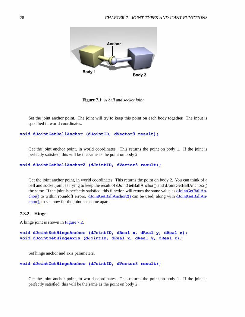
A ball and socket joint is shown inFigure 7.1.
void dJointSetBallAnchor (dJointID, dReal x, dReal y, dReal z);
28 CHAPTER 7. JOINT TYPES AND JOINT FUNCTIONS
Figure 7.1: A ball and socket joint.
Set the joint anchor point. The joint will try to keep this point on each body together. The input isspecified in world coordinates.
void dJointGetBallAnchor (dJointID, dVector3 result);
Get the joint anchor point, in world coordinates. This returns the point on body 1. If the joint isperfectly satisfied, this will be the same as the point on body 2.
void dJointGetBallAnchor2 (dJointID, dVector3 result);
Get the joint anchor point, in world coordinates. This returns the point on body 2. You can think of aball and socket joint as trying to keep the result of dJointGetBallAnchor() and dJointGetBallAnchor2()the same. If the joint is perfectly satisfied, this function will return the same value asdJointGetBallAn-chor() to within roundoff errors.dJointGetBallAnchor2()can be used, along withdJointGetBallAn-chor(), to see how far the joint has come apart.
7.3.2 Hinge
A hinge joint is shown inFigure 7.2.
void dJointSetHingeAnchor (dJointID, dReal x, dReal y, dReal z);void dJointSetHingeAxis (dJointID, dReal x, dReal y, dReal z);
Set hinge anchor and axis parameters.
void dJointGetHingeAnchor (dJointID, dVector3 result);
Get the joint anchor point, in world coordinates. This returns the point on body 1. If the joint isperfectly satisfied, this will be the same as the point on body 2.

7.3. JOINT PARAMETER SETTING FUNCTIONS 29
Figure 7.2: A hinge joint.
void dJointGetHingeAnchor2 (dJointID, dVector3 result);
Get the joint anchor point, in world coordinates. This returns the point on body 2. If the joint isperfectly satisfied, this will return the same value asdJointGetHingeAnchor(). If not, this value will beslightly different. This can be used, for example, to see how far the joint has come apart.
void dJointGetHingeAxis (dJointID, dVector3 result);
Get hinge axis parameter.
dReal dJointGetHingeAngle (dJointID);dReal dJointGetHingeAngleRate (dJointID);
Get the hinge angle and the time derivative of this value. The angle is measured between the twobodies, or between the body and the static environment. The angle will be between -pi..pi.
When the hinge anchor or axis is set, the current position of the attached bodies is examined and thatposition will be the zero angle.
7.3.3 Slider
A slider joint is shown inFigure 7.3.
void dJointSetSliderAxis (dJointID, dReal x, dReal y, dReal z);
Set the slider axis parameter.
void dJointGetSliderAxis (dJointID, dVector3 result);
Get the slider axis parameter.

30 CHAPTER 7. JOINT TYPES AND JOINT FUNCTIONS
Figure 7.3: A slider joint.
Figure 7.4: A universal joint.
dReal dJointGetSliderPosition (dJointID);dReal dJointGetSliderPositionRate (dJointID);
Get the slider linear position (i.e. the slider’s “extension”) and the time derivative of this value.
When the axis is set, the current position of the attached bodies is examined and that position will bethe zero position.
7.3.4 Universal
A universal joint is shown inFigure 7.4.A universal joint is like a ball and socket joint that constrains an extra degree of rotational freedom.
Given axis 1 on body 1, and axis 2 on body 2 that is perpendicular to axis 1, it keeps them perpendicular. Inother words, rotation of the two bodies about the direction perpendicular to the two axes will be equal.
In the picture, the two bodies are joined together by a cross. Axis 1 is attached to body 1, and axis 2 isattached to body 2. The cross keeps these axes at 90 degrees, so if you grab body 1 and twist it, body 2 willtwist as well.

7.3. JOINT PARAMETER SETTING FUNCTIONS 31
A Universal joint is equivalent to a hinge-2 joint where the hinge-2’s axes are perpendicular to eachother, and with a perfectly rigid connection in place of the suspension.
Universal joints show up in cars, where the engine causes a shaft, the drive shaft, to rotate along its ownaxis. At some point you’d like to change the direction of the shaft. The problem is, if you just bend theshaft, then the part after the bend won’t rotate about its own axis. So if you cut it at the bend location andinsert a universal joint, you can use the constraint to force the second shaft to rotate about the same angle asthe first shaft.
Another use of this joint is to attach the arms of a simple virtual creature to its body. Imagine a personholding their arms straight out. You may want the arm to be able to move up and down, and forward andback, but not to rotate about its own axis.
Here are the universal joint functions:
void dJointSetUniversalAnchor (dJointID, dReal x, dReal y, dReal z);void dJointSetUniversalAxis1 (dJointID, dReal x, dReal y, dReal z);void dJointSetUniversalAxis2 (dJointID, dReal x, dReal y, dReal z);
Set universal anchor and axis parameters. Axis 1 and axis 2 should be perpendicular to each other.
void dJointGetUniversalAnchor (dJointID, dVector3 result);
Get the joint anchor point, in world coordinates. This returns the point on body 1. If the joint isperfectly satisfied, this will be the same as the point on body 2.
void dJointGetUniversalAnchor2 (dJointID, dVector3 result);
Get the joint anchor point, in world coordinates. This returns the point on body 2. You can think ofthe ball and socket part of a universal joint as trying to keep the result of dJointGetBallAnchor() anddJointGetBallAnchor2() the same. If the joint is perfectly satisfied, this function will return the samevalue asdJointGetUniversalAnchor()to within roundoff errors.dJointGetUniversalAnchor2()can beused, along withdJointGetUniversalAnchor(), to see how far the joint has come apart.
void dJointGetUniversalAxis1 (dJointID, dVector3 result);void dJointGetUniversalAxis2 (dJointID, dVector3 result);
Get univeral axis parameters.
dReal dJointGetUniversalAngle1 (dJointID);dReal dJointGetUniversalAngle2 (dJointID);dReal dJointGetUniversalAngleRate1 (dJointID);dReal dJointGetUniversalAngleRate2 (dJointID);
Get the universal angles and the time derivatives of these values. The angle is measured between abody and the cross, or between the static environment and the cross. The angle will be between -pi..pi.
When the universal anchor or axis is set, the current position of the attached bodies is examined andthat position will be the zero angle.

32 CHAPTER 7. JOINT TYPES AND JOINT FUNCTIONS
Figure 7.5: A hinge-2 joint.
7.3.5 Hinge-2
A hinge-2 joint is shown inFigure 7.5.The hinge-2 joint is the same as two hinges connected in series, with different hinge axes. An example,
shown in the above picture is the steering wheel of a car, where one axis allows the wheel to be steered andthe other axis allows the wheel to rotate.
The hinge-2 joint has an anchor point and two hinge axes. Axis 1 is specified relative to body 1 (thiswould be the steering axis if body 1 is the chassis). Axis 2 is specified relative to body 2 (this would be thewheel axis if body 2 is the wheel).
Axis 1 can have joint limits and a motor, axis 2 can only have a motor.Axis 1 can function as a suspension axis, i.e. the constraint can be compressible along that axis.The hinge-2 joint where axis1 is perpendicular to axis 2 is equivalent to a universal joint with added
suspension.
void dJointSetHinge2Anchor (dJointID, dReal x, dReal y, dReal z);void dJointSetHinge2Axis1 (dJointID, dReal x, dReal y, dReal z);void dJointSetHinge2Axis2 (dJointID, dReal x, dReal y, dReal z);
Set hinge-2 anchor and axis parameters. Axis 1 and axis 2 must not lie along the same line.
void dJointGetHinge2Anchor (dJointID, dVector3 result);
Get the joint anchor point, in world coordinates. This returns the point on body 1. If the joint isperfectly satisfied, this will be the same as the point on body 2.
void dJointGetHinge2Anchor2 (dJointID, dVector3 result);
Get the joint anchor point, in world coordinates. This returns the point on body 2. If the joint isperfectly satisfied, this will return the same value asdJointGetHinge2Anchor(). If not, this value willbe slightly different. This can be used, for example, to see how far the joint has come apart.

7.3. JOINT PARAMETER SETTING FUNCTIONS 33
Figure 7.6: A contact joint.
void dJointGetHinge2Axis1 (dJointID, dVector3 result);void dJointGetHinge2Axis2 (dJointID, dVector3 result);
Get hinge-2 axis parameters.
dReal dJointGetHinge2Angle1 (dJointID);dReal dJointGetHinge2Angle1Rate (dJointID);dReal dJointGetHinge2Angle2Rate (dJointID);
Get the hinge-2 angles (around axis 1 and axis 2) and the time derivatives of these values.
When the anchor or axis is set, the current position of the attached bodies is examined and that positionwill be the zero angle.
7.3.6 Fixed
The fixed joint maintains a fixed relative position and orientation between two bodies, or between a bodyand the static environment. Using this joint is almost never a good idea in practice, except when debugging.If you need two bodies to be glued together it is better to represent that as a single body.
void dJointSetFixed (dJointID);
Call this on the fixed joint after it has been attached to remember the current desired relative offset anddesired relative rotation between the bodies.
7.3.7 Contact
A contact joint is shown inFigure 7.6.The contact joint prevents body 1 and body 2 from inter-penetrating at the contact point. It does this by
only allowing the bodies to have an “outgoing” velocity in the direction of the contact normal. Contact jointstypically have a lifetime of one time step. They are created and deleted in response to collision detection.
34 CHAPTER 7. JOINT TYPES AND JOINT FUNCTIONS
Contact joints can simulate friction at the contact by applying special forces in the two friction directionsthat are perpendicular to the normal.
When a contact joint is created, adContact structure must be supplied. This has the following defini-tion:
struct dContact {dSurfaceParameters surface;dContactGeom geom;dVector3 fdir1;
};
geom is a substructure that is set by the collision functions. It is described in the collision section.fdir1 is a ”first friction direction” vector that defines a direction along which frictional force is applied.
It must be of unit length and perpendicular to the contact normal (so it is typically tangential to the contactsurface). It should only be defined if the dContactFDir1 flag is set insurface.mode . The ”second frictiondirection” is a vector computed to be perpendicular to both the contact normal andfdir1 .
surface is a substructure that is set by the user. Its members define the properties of the collidingsurfaces. It has the following members:
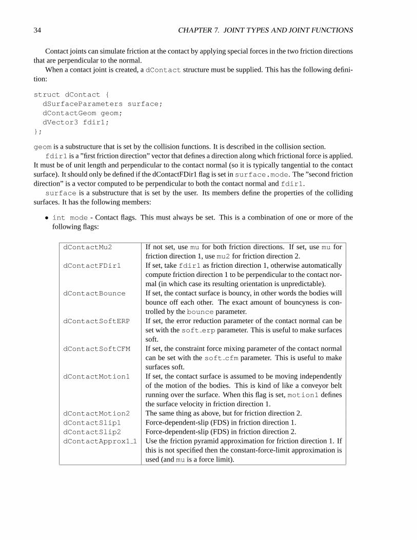
• int mode - Contact flags. This must always be set. This is a combination of one or more of thefollowing flags:
dContactMu2 If not set, usemu for both friction directions. If set, usemu forfriction direction 1, usemu2 for friction direction 2.
dContactFDir1 If set, takefdir1 as friction direction 1, otherwise automaticallycompute friction direction 1 to be perpendicular to the contact nor-mal (in which case its resulting orientation is unpredictable).
dContactBounce If set, the contact surface is bouncy, in other words the bodies willbounce off each other. The exact amount of bouncyness is con-trolled by thebounce parameter.
dContactSoftERP If set, the error reduction parameter of the contact normal can beset with thesoft erp parameter. This is useful to make surfacessoft.
dContactSoftCFM If set, the constraint force mixing parameter of the contact normalcan be set with thesoft cfm parameter. This is useful to makesurfaces soft.
dContactMotion1 If set, the contact surface is assumed to be moving independentlyof the motion of the bodies. This is kind of like a conveyor beltrunning over the surface. When this flag is set,motion1 definesthe surface velocity in friction direction 1.
dContactMotion2 The same thing as above, but for friction direction 2.dContactSlip1 Force-dependent-slip (FDS) in friction direction 1.dContactSlip2 Force-dependent-slip (FDS) in friction direction 2.dContactApprox1 1 Use the friction pyramid approximation for friction direction 1. If
this is not specified then the constant-force-limit approximation isused (andmuis a force limit).

7.3. JOINT PARAMETER SETTING FUNCTIONS 35
dContactApprox1 2 Use the friction pyramid approximation for friction direction 2. Ifthis is not specified then the constant-force-limit approximation isused (andmuis a force limit).
dContactApprox1 Equivalent to both dContactApprox1 1 anddContactApprox1 2.
• dReal mu : Coulomb friction coefficient. This must be in the range 0 todInfinity . 0 resultsin a frictionless contact, anddInfinity results in a contact that never slips. Note that frictionlesscontacts are less time consuming to compute than ones with friction, and infinite friction contacts canbe cheaper than contacts with finite friction. This must always be set.
• dReal mu2 : Optional Coulomb friction coefficient for friction direction 2 (0..dInfinity ). Thisis only set if the corresponding flag is set inmode.
• dReal bounce : Restitution parameter (0..1). 0 means the surfaces are not bouncy at all, 1 ismaximum bouncyness. This is only set if the corresponding flag is set inmode.
• dReal bounce vel : The minimum incoming velocity necessary for bounce. Incoming velocitiesbelow this will effectively have a bounce parameter of 0. This is only set if the corresponding flag isset inmode.
• dReal soft erp : Contact normal “softness” parameter. This is only set if the corresponding flagis set inmode.
• dReal soft cfm : Contact normal “softness” parameter. This is only set if the corresponding flagis set inmode.
• dReal motion1,motion2 : Surface velocity in friction directions 1 and 2. These are only set ifthe corresponding flags are set inmode.
• dReal slip1,slip2 : The coefficients of force-dependent-slip (FDS) for friction directions 1and 2. These are only set if the corresponding flags are set inmode.
FDS is an effect that causes the contacting surfaces to side past each other with a velocity that isproportional to the force that is being applied tangentially to that surface.
Consider a contact point where the coefficient of frictionµ is infinite. Normally, if a forcef isapplied to the two contacting surfaces, to try and get them to slide past each other, they will not move.However, if the FDS coefficient is set to a positive valuek then the surfaces will slide past each other,building up to a steady velocity ofk ∗ f relative to each other.
Note that this is quite different from normal frictional effects: the force does not cause a constantaccelerationof the surfaces relative to each other - it causes a brief acceleration to achieve the steadyvelocity.
This is useful for modeling some situations, in particular tires. For example consider a car at rest ona road. Pushing the car in its direction of travel will cause it to start moving (i.e. the tires will startrolling). Pushing the car in the perpendicular direction will have no effect, as the tires do not roll inthat direction. However - if the car is moving at a velocityv, applying a forcef in the perpendiculardirection will cause the tires to slip on the road with a velocity proportional tof ∗ v (Yes, this reallyhappens).
36 CHAPTER 7. JOINT TYPES AND JOINT FUNCTIONS
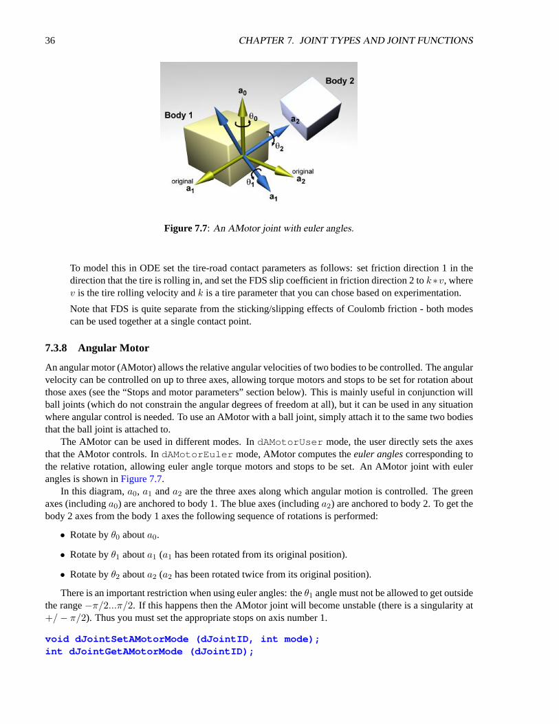
Figure 7.7: An AMotor joint with euler angles.
To model this in ODE set the tire-road contact parameters as follows: set friction direction 1 in thedirection that the tire is rolling in, and set the FDS slip coefficient in friction direction 2 tok∗v, wherev is the tire rolling velocity andk is a tire parameter that you can chose based on experimentation.
Note that FDS is quite separate from the sticking/slipping effects of Coulomb friction - both modescan be used together at a single contact point.
7.3.8 Angular Motor
An angular motor (AMotor) allows the relative angular velocities of two bodies to be controlled. The angularvelocity can be controlled on up to three axes, allowing torque motors and stops to be set for rotation aboutthose axes (see the “Stops and motor parameters” section below). This is mainly useful in conjunction willball joints (which do not constrain the angular degrees of freedom at all), but it can be used in any situationwhere angular control is needed. To use an AMotor with a ball joint, simply attach it to the same two bodiesthat the ball joint is attached to.
The AMotor can be used in different modes. IndAMotorUser mode, the user directly sets the axesthat the AMotor controls. IndAMotorEuler mode, AMotor computes theeuler anglescorresponding tothe relative rotation, allowing euler angle torque motors and stops to be set. An AMotor joint with eulerangles is shown inFigure 7.7.
In this diagram,a0, a1 anda2 are the three axes along which angular motion is controlled. The greenaxes (includinga0) are anchored to body 1. The blue axes (includinga2) are anchored to body 2. To get thebody 2 axes from the body 1 axes the following sequence of rotations is performed:
• Rotate byθ0 abouta0.
• Rotate byθ1 abouta1 (a1 has been rotated from its original position).
• Rotate byθ2 abouta2 (a2 has been rotated twice from its original position).
There is an important restriction when using euler angles: theθ1 angle must not be allowed to get outsidethe range−π/2...π/2. If this happens then the AMotor joint will become unstable (there is a singularity at+/− π/2). Thus you must set the appropriate stops on axis number 1.
void dJointSetAMotorMode (dJointID, int mode);int dJointGetAMotorMode (dJointID);

7.3. JOINT PARAMETER SETTING FUNCTIONS 37
Set (and get) the angular motor mode. Themode parameter must be one of the following constants:
dAMotorUser The AMotor axes and joint angle settings are entirely controlledby the user. This is the default mode.
dAMotorEuler Euler angles are automatically computed. The axisa1 is also auto-matically computed. The AMotor axes must be set correctly whenin this mode, as described below. When this mode is initially setthe current relative orientations of the bodies will correspond to alleuler angles at zero.
void dJointSetAMotorNumAxes (dJointID, int num);int dJointGetAMotorNumAxes (dJointID);
Set (and get) the number of angular axes that will be controlled by the AMotor. The argumentnumcan range from 0 (which effectively deactivates the joint) to 3. This is automatically set to 3 indAMotorEuler mode.
void dJointSetAMotorAxis (dJointID, int anum, int rel,dReal x, dReal y, dReal z);
void dJointGetAMotorAxis (dJointID, int anum, dVector3 result);int dJointGetAMotorAxisRel (dJointID, int anum);
Set (and get) the AMotor axes. Theanumargument selects the axis to change (0,1 or 2). Each axis canhave one of three “relative orientation” modes, selected byrel :
• 0: The axis is anchored to the global frame.
• 1: The axis is anchored to the first body.
• 2: The axis is anchored to the second body.
The axis vector (x ,y ,z ) is always specified in global coordinates regardless of the setting ofrel . Thereare twoGetAMotorAxis functions, one to return the axis and one to return the relative mode.
For dAMotorEuler mode:
• Only axes 0 and 2 need to be set. Axis 1 will be determined automatically at each time step.
• Axes 0 and 2 must be perpendicular to each other.
• Axis 0 must be anchored to the first body, axis 2 must be anchored to the second body.
void dJointSetAMotorAngle (dJointID, int anum, dReal angle);
Tell the AMotor what the current angle is along axisanum. This function should only be called indAMotorUser mode, because in this mode the AMotor has no other way of knowing the joint angles.The angle information is needed if stops have been set along the axis, but it is not needed for axismotors.
dReal dJointGetAMotorAngle (dJointID, int anum);

38 CHAPTER 7. JOINT TYPES AND JOINT FUNCTIONS
Return the current angle for axisanum. In dAMotorUser mode this is simply the value that was setwith dJointSetAMotorAngle(). In dAMotorEuler mode this is the corresponding euler angle.
dReal dJointGetAMotorAngleRate (dJointID, int anum);
Return the current angle rate for axisanum. In dAMotorUser mode this is always zero, as not enoughinformation is available. IndAMotorEuler mode this is the corresponding euler angle rate.
7.4 General
The joint geometry parameter setting functions should only be called after the joint has been attached tobodies, and those bodies have been correctly positioned, otherwise the joint may not be initialized correctly.If the joint is not already attached, these functions will do nothing.
For the parameter getting functions, if the system is out of alignment (i.e. there is some joint error) thenthe anchor/axis values will be correct with respect to body 1 only (or body 2 if you specified body 1 as zeroin thedJointAttach()function).
The default anchor for all joints is (0,0,0). The default axis for all joints is (1,0,0).When an axis is set it will be normalized to unit length. The adjusted axis is what the axis getting
functions will return.When measuring a joint angle or position, a value of zero corresponds to the initial position of the bodies
relative to each other.Note that there are no functions to set joint angles or positions (or their rates) directly, instead you must
set the corresponding body positions and velocities.
7.5 Stop and motor parameters
When a joint is first created there is nothing to prevent it from moving through its entire range of motion.For example a hinge will be able to move through its entire angle, and a slider will slide to any length.
This range of motion can be limited by setting stops on the joint. The joint angle (or position) will beprevented from going below the low stop value, or from going above the high stop value. Note that a jointangle (or position) of zero corresponds to the initial body positions.
As well as stops, many joint types can have motors. A motor applies a torque (or force) to a joint’sdegree(s) of freedom to get it to pivot (or slide) at a desired speed. Motors have force limits, which meansthey can apply no more than a given maximum force/torque to the joint.
Motors have two parameters: a desired speed, and the maximum force that is available to reach thatspeed. This is a very simple model of real life motors, engines or servos. However, is it quite useful whenmodeling a motor (or engine or servo) that is geared down with a gearbox before being connected to thejoint. Such devices are often controlled by setting a desired speed, and can only generate a maximum amountof power to achieve that speed (which corresponds to a certain amount of force available at the joint).
Motors can also be used to accurately model dry (or Coulomb) friction in joints. Simply set the desiredvelocity to zero and set the maximum force to some constant value - then all joint motion will be impededby that force.
The alternative to using joint stops and motors is to simply apply forces to the affected bodies yourself.Applying motor forces is easy, and joint stops can be emulated with restraining spring forces. Howeverapplying forces directly is often not a good approach and can lead to severe stability problems if it is notdone carefully.

7.5. STOP AND MOTOR PARAMETERS 39
Consider the case of applying a force to a body to achieve a desired velocity. To calculate this force youuse information about the current velocity, something like this:
force = k ∗ (desiredspeed− currentspeed) (7.1)
This has several problems. First, the parameterk must be tuned by hand. If it is too low the body willtake a long time to come up to speed. If it is too high the simulation will become unstable. Second, even ifk is chosen well the body will still take a few time steps to come up to speed. Third, if any other “external”forces are being applied to the body, the desired velocity may never even be reached (a more complicatedforce equation would be needed, which would have extra parameters and its own problems).
Joint motors solve all these problems: they bring the body up to speed in one time step, provided thatdoes not take more force than is allowed. Joint motors need no extra parameters because they are actuallyimplemented as constraints. They can effectively see one time step into the future to work out the correctforce. This makes joint motors more computationally expensive than computing the forces yourself, butthey are much more robust and stable, and far less time consuming to design with. This is especially truewith larger rigid body systems.
Similar arguments apply to joint stops.
7.5.1 Parameter Functions
Here are the functions that set stop and motor parameters (as well as other kinds of parameters) on a joint:
void dJointSetHingeParam (dJointID, int parameter, dReal value);void dJointSetSliderParam (dJointID, int parameter, dReal value);void dJointSetHinge2Param (dJointID, int parameter, dReal value);void dJointSetUniversalParam (dJointID, int parameter, dReal value);void dJointSetAMotorParam (dJointID, int parameter, dReal value);dReal dJointGetHingeParam (dJointID, int parameter);dReal dJointGetSliderParam (dJointID, int parameter);dReal dJointGetHinge2Param (dJointID, int parameter);dReal dJointGetUniversalParam (dJointID, int parameter);dReal dJointGetAMotorParam (dJointID, int parameter);
Set/get limit/motor parameters for each joint type. The parameter numbers are:
dParamLoStop Low stop angle or position. Setting this to-dInfinity (thedefault value) turns off the low stop. For rotational joints, this stopmust be greater than−π to be effective.
dParamHiStop High stop angle or position. Setting this todInfinity (the de-fault value) turns off the high stop. For rotational joints, this stopmust be less thanπ to be effective. If the high stop is less than thelow stop then both stops will be ineffective.
dParamVel Desired motor velocity (this will be an angular or linear velocity).dParamFMax The maximum force or torque that the motor will use to achieve
the desired velocity. This must always be greater than or equal tozero. Setting this to zero (the default value) turns off the motor.
40 CHAPTER 7. JOINT TYPES AND JOINT FUNCTIONS
dParamFudgeFactor The current joint stop/motor implementation has a small problem:when the joint is at one stop and the motor is set to move it awayfrom the stop, too much force may be applied for one time step,causing a “jumping” motion. This fudge factor is used to scalethis excess force. It should have a value between zero and one (thedefault value). If the jumping motion is too visible in a joint, thevalue can be reduced. Making this value too small can prevent themotor from being able to move the joint away from a stop.
dParamBounce The bouncyness of the stops. This is a restitution parameter inthe range 0..1. 0 means the stops are not bouncy at all, 1 meansmaximum bouncyness.
dParamCFM The constraint force mixing (CFM) value used when not at a stop.dParamStopERP The error reduction parameter (ERP) used by the stops.dParamStopCFM The constraint force mixing (CFM) value used by the stops. To-
gether with the ERP value this can be used to get spongy or softstops. Note that this is intended for unpowered joints, it does notreally work as expected when a powered joint reaches its limit.
dParamSuspensionERP Suspension error reduction parameter (ERP). Currently this is onlyimplemented on the hinge-2 joint.
dParamSuspensionCFM Suspension constraint force mixing (CFM) value. Currently this isonly implemented on the hinge-2 joint.
If a particular parameter is not implemented by a given joint, setting it will have no effect.
These parameter names can be optionally followed by a digit (2 or 3) to indicate the second or thirdset of parameters, e.g. for the second axis in a hinge-2 joint, or the third axis in an AMotor joint.A constantdParamGroup is also defined such that:dParamXi = dParamX + dParamGroup *(i− 1)
7.6 Setting Joint Torques/Forces Directly
Motors (see above) allow you to set joint velocities directly. However, you may instead wish to set the torqueor force at a joint instead. These functions do just that. Note that they don’t affect the motor, but simply calldBodyAddForce()/dBodyAddTorque()on the bodies attached to it.
dJointAddHingeTorque(dJointID joint, dReal torque)
Applies the torque about the hinge axis. That is, it applies a torque with magnitudetorque , in thedirection of the hinge axis, to body 1, and with the same magnitude but in opposite direction to body 2.This function is just a wrapper fordBodyAddTorque()
dJointAddUniversalTorques(dJointID joint, dReal torque1, dReal torque2)
Applies torque1 about the universal’s axis 1, andtorque2 about the universal’s axis 2. Thisfunction is just a wrapper fordBodyAddTorque().
dJointAddSliderForce(dJointID joint, dReal force)

7.6. SETTING JOINT TORQUES/FORCES DIRECTLY 41
Applies the given force in the slider’s direction. That is, it applies a force with magnitudeforce , inthe direction slider’s axis, to body1, and with the same magnitude but opposite direction to body2. Thisfunction is just a wrapper fordBodyAddForce().
dJointAddHinge2Torques(dJointID joint, dReal torque1, dReal torque2)
Applies torque1 about the hinge2’s axis 1, andtorque2 about the hinge2’s axis 2. This functionis just a wrapper fordBodyAddTorque().
dJointAddAMotorTorques(dJointID joint, dReal torque0, dReal torque1,dReal torque2)
Applies torque0 about the AMotor’s axis 0,torque1 about the AMotor’s axis 1, andtorque2about the AMotor’s axis 2. If the motor has fewer than three axes, the higher torques are ignored. Thisfunction is just a wrapper fordBodyAddTorque().

42 CHAPTER 7. JOINT TYPES AND JOINT FUNCTIONS

Chapter 8
StepFast
NOTE: The StepFast algorithm has been superseded by the QuickStep algorithm: see thedWorldQuick-Step() function. However, much of the following discussion also applies to QuickStep, except for thedetails of the method used.
ODE’s dWorldStep()function currently uses a ”big matrix” method to step the system. For some largesystems this can be slow and can require a lot of memory. The StepFast1 algorithm provides an alternativeway to step the system, that sacrifices some accuracy for a big gain in speed and memory. To use it, yousimply calldWorldStepFast1()instead ofdWorldStep().
The chart inFigure 8.1illustrates this speed advantage over the standarddWorldStep()algorithm.The graph relates the number of Degrees Of Freedom (DOFs) removed from a system to the running
time of the step. You may be able to tell that thedWorldStep()algorithm’s running time is proportionalto the cube of the number of DOF’s removed. The StepFast1 algorithm, however, is roughly linear. So asislands increase in size (for example, when there is a large pile-up of cars, a pile of ”ragdoll corpses”, or awall of bricks) the StepFast1 algorithm scales better thandWorldStep(). All this means that your applicationis more likely to keep a steady framerate, even in the worst case scenario.
The graph of DOFs removed to memory looks quite similar (seeFigure 8.2).dWorldStep()requires memory proportional only to the square of the number of DOF’s removed. Step-
Fast1, though, is still linear, but it has nothing to do with the number of iterations per step. So this meansthe dreaded ”There was a big pile-up and ODE crashed without an error message” problems (usually stackoverflows) won’t happen with StepFast1. Or at least that you’ll be rendering at a minute per frame or slowerbefore they do.
8.1 When to use StepFast1
As shown above, StepFast1 is quite good when it comes to speed and memory usage. All this power doesn’tcome for free, though; all optimizations are a trade-off of one kind or another. I’ve already mentioned thatStepFast1 trades off accuracy for it’s speed and memory advantages. You actually get to choose just howmuch accuracy you give away though, at the cost of speed, by adjusting the number of iterations per step.Though you may never reach the accuracy ofdWorldStep()(or you may surpass it, depending on the type ofinaccuracy), you can be almost certain that a larger number of iterations will give you more accurate results(more slowly). So StepFast1 can be used in a good variety of situations.
The general answer to this question then, is: use StepFast1 when you don’t mind having a few moreparameters to play with to get the system stable, and you want to take advantage of it’s speed or memoryadvantages. If you find yourself running into situations in your simulation where large numbers of bodies
43
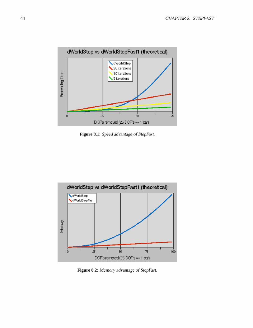
44 CHAPTER 8. STEPFAST
Figure 8.1: Speed advantage of StepFast.
Figure 8.2: Memory advantage of StepFast.

8.2. WHEN NOT TO USE STEPFAST1 45
come in contact, anddWorldStep()becomes too slow, try switching to StepFast1. Many systems will workjust fine with nothing more than changing thedWorldStep()function call todWorldStepFast1(). Others willrequire a little tweaking to get them to work well with StepFast1, usually in the masses of the bodies. Whena joint connects two bodies with a large mass ratio (i.e. one body has several times the mass of the otherbody) StepFast1 may have trouble solving it.
Another prospect for StepFast1 is designing for it from the ground up. If you know you are going to buildlarge worlds with many physically based objects in them, then go ahead and plan to use StepFast1. Notingthe mass ratio problem above, you might want to consider making the mass of every body in your systemequal to 1.0. Or in a very small range, for example between 0.5 and 1.5. Most of the other suggestionsfor speed and stability apply to StepFast1, except that the object is no longer to remove as many joints aspossible from the equation. It can likely be shown that you will get a better performance to stability ratio byspreading out mass among several bodies connected by fixed joints rather than trying to implement it as onemassive body, especially if that one massive body means you have to switch back todWorldStep()to keepthings stable.
A final prospect for StepFast1 is to use it only when you need to. Since StepFast1 uses the body andworld structures in exactly the same way asdWorldStep(), you can actually switch back and forth betweenthe two solvers at will. A good heuristic for when to make this switch is to simply count contact joints whileyou are running the collision detection. Since collision detection is normally called before the step, usingthis method will ensure that the large island that would slow you down is never sent to thedWorldStep()solver (as opposed to waiting until after you’ve already taken a step at 1 fps...). The only better solutionwould be a hybrid island creation function, that sends small islands todWorldStep(), and large islands todWorldStepFast1(). This may make it in the source at some point in the future.
8.2 When NOT to use StepFast1
Though there are several specific situations when it as advisable not to use StepFast1, I believe they can allbe summed up in a single statement: Don’t use StepFast1 when accuracy is more important than speed ormemory to you. You may still want to evaluate it in this case and see if the inaccuracies are even noticeable,perhaps with a relatively large number of iterations (20+).
8.3 How it works
For any interested parties out there, here’s a quick rundown of how the StepFast1 algorithm works. Thegeneral problem that ODE tries to solve is a system of linear (in)equalities in (m = constraints) unknowns,where one constraint constrains 1 Degree of Freedom in one joint. For large islands of bodies with manyjoints between them, this can take a rather largeO(m2) array, which takesO(m3) time to solve. StepFast1completely avoids creating the large matrix by making an assumption: at relatively small timesteps, theeffect of any given joint is so localized that it can be calculated without respect to any other joint in thesystem, and any conflicting joints will cancel each other out before the body actually moves. So StepFast1uses the same solution method (LCP) to solve the same problem, only localized to a single joint (wherem ¡= 6). It gets away with this by sub-dividing the timestep and repeating the process over really smalltimesteps (i = maxiterations) times. So the running time of StepFast1 is ”roughly”O(mi). It’s really closerto O(ji(m/j)3) = O(mi(m/j)2), wherej = joints, but(m/j) is never ¿ 6, so(m/j)2 is factored out as aconstant.
46 CHAPTER 8. STEPFAST
8.4 Experimental Utilities included with StepFast1
Several experimental functions have been added to ODE as part of the StepFast1 flow of code, at least untilthey are validated. Most have to do with the automatic disabling and enabling of bodies as yet another bit ofoptimization. Here’s the general idea:
• The body is considered a candidate for disabling when it falls below a certain speed (linear and angu-lar), called the AutoDisableThreshold. In the interest of speedy execution, the actual speed measuredis the square of the speed of the body. So you may need to set a lower value than you expected. 0.003works well in testcrash, and is the default.
• When the body has remained a disable candidate for a certain number of steps (AutoDisableSteps), itis disabled. This is almost completely for boxes, which like to land and bounce up on two points, andteeter motionless for a few steps before falling back down. Round items generally need a much lower(like 1) AutoDisableSteps than boxes do (10+), 10 is the default.
• AutoDisabling is disabled by default, use dBodySetAutoDisableSF1(body, true) to enable it.
• A body is automatically re-enabled when it comes in contact with another enabled body.
• Enabled bodies only enable bodies within (AutoEnableDepth) bodies of them each step. This, inconjunction with AutoDisabling, causes a rim of bodies that are enabled and disabled each step toform, containing the enabled bodies to the smallest area allowed by the AutoDisable parameters.Setting AutoEnableDepth to a really large number will retain the current functionality. Setting it to 0will give you a new functionality: disabled bodies will never be automatically re-enabled, acting likegeoms only. 3 seems to be a good value for the wall in testcrash, but 1000 is the default to retainstandard functionality.
Note that the functions pertaining to auto-disabling are not yet implemented!
8.5 API
void dWorldStepFast1(dWorldID, dReal stepsize, int maxiterations);
Step the world bystepsize seconds using the StepFast1 algorithm. The number of iterations toperform is given bymaxiterations .
void dWorldSetAutoEnableDepthSF1(dWorldID, int autoEnableDepth);int dWorldGetAutoEnableDepthSF1(dWorldID);
Set and get the AutoEnableDepth parameter used by the StepFast1 algorithm.
void dBodySetAutoDisableThresholdSF1(dBodyID, dReal autoDisableThreshold);dReal dBodyGetAutoDisableThresholdSF1(dBodyID);
Set and get the per-body AutoDisableThreshold parameter used by the StepFast1 algorithm.

8.5. API 47
void dBodySetAutoDisableStepsSF1(dBodyID, int AutoDisableSteps);int dBodyGetAutoDisableStepsSF1(dBodyID);
Set and get the per-body AutoDisableSteps parameter used by the StepFast1 algorithm.
void dBodySetAutoDisableSF1(dBodyID, int doAutoDisable);int dBodyGetAutoDisableSF1(dBodyID);
Set and get the per-body AutoDisable flag used by the StepFast1 algorithm. IfdoAutoDisable isnonzero, auto-disabling is enabled. IfdoAutoDisable is zero, auto-disabling is disabled.

48 CHAPTER 8. STEPFAST
Chapter 9
Support Functions
9.1 Rotation functions
Rigid body orientations are represented with quaternions. A quaternion is four numbers[cos(θ/2), sin(θ/2)∗u] whereθ is a rotation angle andu is a unit length rotation axis.
Every rigid body also has a 3x3 rotation matrix that is derived from the quaternion. The rotation matrixand the quaternion always match.
Some information about quaternions:
• q and -q represent the same rotation.
• The inverse of a quaternion is[q[0]− q[1]− q[2]− q[3]].
The following are utility functions for dealing with rotation matrices and quaternions.
void dRSetIdentity (dMatrix3 R);
SetR to the identity matrix (i.e. no rotation).
void dRFromAxisAndAngle (dMatrix3 R,dReal ax, dReal ay, dReal az, dReal angle);
Compute the rotation matrixRas a rotation ofangle radians along the axis (ax ,ay ,az ).
void dRFromEulerAngles (dMatrix3 R,dReal phi, dReal theta, dReal psi);
Compute the rotation matrixR from the three Euler rotation angles.
void dRFrom2Axes (dMatrix3 R, dReal ax, dReal ay, dReal az,dReal bx, dReal by, dReal bz);
Compute the rotation matrixR from the two vectors ‘a’ (ax ,ay ,az ) and ‘b’ (bx ,by ,bz ). ‘a’ and ‘b’are the desired x and y axes of the rotated coordinate system. If necessary, ‘a’ and ‘b’ will be madeunit length, and ‘b’ will be projected so that it is perpendicular to ‘a’. The desired z axis is the crossproduct of ‘a’ and ‘b’.
49

50 CHAPTER 9. SUPPORT FUNCTIONS
void dQSetIdentity (dQuaternion q);
Setq to the identity rotation (i.e. no rotation).
void dQFromAxisAndAngle (dQuaternion q, dReal ax, dReal ay, dReal az,dReal angle);
Computeq as a rotation ofangle radians along the axis (ax ,ay ,az ).
void dQMultiply0 (dQuaternion qa,const dQuaternion qb, const dQuaternion qc);
void dQMultiply1 (dQuaternion qa,const dQuaternion qb, const dQuaternion qc);
void dQMultiply2 (dQuaternion qa,const dQuaternion qb, const dQuaternion qc);
void dQMultiply3 (dQuaternion qa,const dQuaternion qb, const dQuaternion qc);
Setqa = qb*qc . This is that same asqa = rotationqc followed by rotationqb . The 0/1/2 versions areanalogous to the multiply functions, i.e. 1 uses the inverse ofqb , and 2 uses the inverse ofqc . Option3 uses the inverse of both.
void dQtoR (const dQuaternion q, dMatrix3 R);
Convert quaternionq to rotation matrixR.
void dRtoQ (const dMatrix3 R, dQuaternion q);
Convert rotation matrixR to quaternionq.
void dWtoDQ (const dVector3 w, const dQuaternion q, dVector4 dq);
Given an existing orientationq and an angular velocity vectorw, return indq the resulting dq/dt.
9.2 Mass functions
The mass parameters of a rigid body are described by adMass structure:
typedef struct dMass {dReal mass; // total mass of the rigid bodydVector4 c; // center of gravity position in body frame (x,y,z)dMatrix3 I; // 3x3 inertia tensor in body frame, about POR
} dMass;
The following functions operate on this structure:

9.2. MASS FUNCTIONS 51
void dMassSetZero (dMass *);
Set all the mass parameters to zero.
void dMassSetParameters (dMass *, dReal themass,dReal cgx, dReal cgy, dReal cgz,dReal I11, dReal I22, dReal I33,dReal I12, dReal I13, dReal I23);
Set the mass parameters to the given values.themass is the mass of the body. (cx ,cy ,cz ) is thecenter of gravity position in the body frame. TheIxx values are the elements of the inertia matrix:
[ I11 I12 I13 ][ I12 I22 I23 ][ I13 I23 I33 ]
void dMassSetSphere (dMass *, dReal density, dReal radius);void dMassSetSphereTotal (dMass *, dReal total_mass, dReal radius);
Set the mass parameters to represent a sphere of the given radius and density, with the center of massat (0,0,0) relative to the body. The first function accepts the density of the sphere, the second acceptsthe total mass of the sphere.
void dMassSetCappedCylinder (dMass *, dReal density, int direction,dReal radius, dReal length);
void dMassSetCappedCylinderTotal (dMass *, dReal total_mass,int direction, dReal radius, dReal length);
Set the mass parameters to represent a capped cylinder of the given parameters and density, with thecenter of mass at (0,0,0) relative to the body. The radius of the cylinder (and the spherical cap) isradius . The length of the cylinder (not counting the spherical cap) islength . The cylinder’s longaxis is oriented along the body’s x, y or z axis according to the value ofdirection (1=x, 2=y, 3=z).The first function accepts the density of the object, the second accepts its total mass.
void dMassSetCylinder (dMass *, dReal density, int direction,dReal radius, dReal length);
void dMassSetCylinderTotal (dMass *, dReal total_mass, int direction,dReal radius, dReal length);
Set the mass parameters to represent a flat-ended cylinder of the given parameters and density, withthe center of mass at (0,0,0) relative to the body. The radius of the cylinder isradius . The length ofthe cylinder islength . The cylinder’s long axis is oriented along the body’s x, y or z axis accordingto the value ofdirection (1=x, 2=y, 3=z). The first function accepts the density of the object, thesecond accepts its total mass.

52 CHAPTER 9. SUPPORT FUNCTIONS
void dMassSetBox (dMass *, dReal density,dReal lx, dReal ly, dReal lz);
void dMassSetBoxTotal (dMass *, dReal total_mass,dReal lx, dReal ly, dReal lz);
Set the mass parameters to represent a box of the given dimensions and density, with the center of massat (0,0,0) relative to the body. The side lengths of the box along the x, y and z axes arelx , ly andlz .The first function accepts the density of the object, the second accepts its total mass.
void dMassAdjust (dMass *, dReal newmass);
Given mass parameters for some object, adjust them so the total mass is nownewmass. This is usefulwhen using the above functions to set the mass parameters for certain objects - they take the objectdensity, not the total mass.
void dMassTranslate (dMass *, dReal x, dReal y, dReal z);
Given mass parameters for some object, adjust them to represent the object displaced by (x ,y ,z ) relativeto the body frame.
void dMassRotate (dMass *, const dMatrix3 R);
Given mass parameters for some object, adjust them to represent the object rotated byR relative to thebody frame.
void dMassAdd (dMass *a, const dMass *b);
Add the massb to the massa.
9.3 Math functions
[There are quite a lot of these, but they’re not standardized enough to document yet].
9.4 Error and memory functions
[Document these later].
Chapter 10
Collision Detection
ODE has two main components: a dynamics simulation engine and a collision detection engine. The colli-sion engine is given information about theshapeof each body. At each time step it figures out which bodiestouch each other and passes the resulting contact point information to the user. The user in turn createscontact joints between bodies.
Using ODE’s collision detection is optional - an alternative collision detection system can be used aslong as it can supply the right kinds of contact information.
10.1 Contact points
If two bodies touch, or if a body touches a static feature in its environment, the contact is represented by oneor more ”contact points”. Each contact point has a correspondingdContactGeom structure:
struct dContactGeom {dVector3 pos; // contact positiondVector3 normal; // normal vectordReal depth; // penetration depthdGeomID g1,g2; // the colliding geoms
};
pos records the contact position, in global coordinates.depth is the depth to which the two bodies inter-penetrate each other. If the depth is zero then the
two bodies have a grazing contact, i.e. they ”only just” touch. However, this is rare - the simulation is notperfectly accurate and will often step the bodies too far so that the depth is nonzero.
normal is a unit length vector that is, generally speaking, perpendicular to the contact surface.g1 andg2 are the geometry objects that collided.The convention is that if body 1 is moved along thenormal vector by a distancedepth (or equivalently
if body 2 is moved the same distance in the opposite direction) then the contact depth will be reduced tozero. This means that the normal vector points ”in” to body 1.
In real life, contact between two bodies is a complex thing. Representing contacts by contact points isonly an approximation. Contact ”patches” or ”surfaces” might be more physically accurate, but representingthese things in high speed simulation software is a challenge.
Each extra contact point added to the simulation will slow it down some more, so sometimes we areforced to ignore contact points in the interests of speed. For example, when two boxes collide many contactpoints may be needed to properly represent the geometry of the situation, but we may choose to keep onlythe best three. Thus we are piling approximation on top of approximation.
53
54 CHAPTER 10. COLLISION DETECTION
10.2 Geoms
Geometry objects (or “geoms” for short) are the fundamental objects in the collision system. A geom canrepresents a single rigid shape (such as a sphere or box), or it can represents a group of other geoms - this isa special kind of geom called a “space”.
Any geom can be collided against any other geom to yield zero or more contact points. Spaces have theextra capability of being able to collide their contained geoms together to yield internal contact points.
Geoms can be placeable or non-placeable. A placeable geom has a position vector and a 3*3 rotationmatrix, just like a rigid body, that can be changed during the simulation. A non-placeable geom does nothave this capability - for example, it may represent some static feature of the environment that can not bemoved. Spaces are non-placeable geoms, because each contained geom may have its own position andorientation but it does not make sense for the space itself to have a position and orientation.
To use the collision engine in a rigid body simulation, placeable geoms are associated with rigid bodyobjects. This allows the collision engine to get the position and orientation of the geoms from the bodies.Note that geoms are distinct from rigid bodies in that a geom has geometrical properties (size, shape, positionand orientation) but no dynamical properties (such as velocity or mass). A body and a geom togetherrepresent all the properties of the simulated object.
Every geom is an instance of aclass, such as sphere, plane, or box. There are a number of built-inclasses, described below, and you can define your own classes as well.
The point of reference of a placeable geoms is the point that is controlled by its position vector. The pointof reference for the standard classes usually corresponds to the geom’s center of mass. This feature allowsthe standard classes to be easily connected to dynamics bodies. If other points of reference are required, atransformation object can be used to encapsulate a geom.
The concepts and functions that apply to all geoms will be described below, followed by the variousgeometry classes and the functions that manipulate them.
10.3 Spaces
A space is a non-placeable geom that can contain other geoms. It is similar to the rigid body concept of the“world”, except that it applies to collision instead of dynamics.
Space objects exist to make collision detection go faster. Without spaces, you might generate contactsin your simulation by callingdCollide() to get contact points for every single pair of geoms. For N geomsthis isO(N2) tests, which is too computationally expensive if your environment has many objects.
A better approach is to insert the geoms into a space and calldSpaceCollide(). The space will thenperform collision culling, which means that it will quickly identify which pairs of geoms arepotentiallyintersecting. Those pairs will be passed to a callback function, which can in turn calldCollide()on them.This saves a lot of time that would have been spent in uselessdCollide() tests, because the number of pairspassed to the callback function will be a small fraction of every possible object-object pair.
Spaces can contain other spaces. This is useful for dividing a collision environment into several hierar-chies to further optimize collision detection speed. This will be described in more detail below.
10.4 General geom functions
The following functions can be applied to any geom.
void dGeomDestroy (dGeomID);
10.4. GENERAL GEOM FUNCTIONS 55
Destroy a geom, removing it from any space it is in first. This one function destroys a geom of anytype, but to create a geom you must call a creation function for that type.
When a space is destroyed, if its cleanup mode is 1 (the default) then all the geoms in that space areautomatically destroyed as well.
void dGeomSetData (dGeomID, void *);void *dGeomGetData (dGeomID);
These functions set and get the user-defined data pointer stored in the geom.
void dGeomSetBody (dGeomID, dBodyID);dBodyID dGeomGetBody (dGeomID);
These functions set and get the body associated with a placeable geom. Setting a body on a geomautomatically combines the position vector and rotation matrix of the body and geom, so that settingthe position or orientation of one will set the value for both objects.
Setting a body ID of zero gives the geom its own position and rotation, independent from any body. Ifthe geom was previously connected to a body then its new independent position/rotation is set to thecurrent position/rotation of the body.
Calling these functions on a non-placeable geom results in a runtime error in the debug build of ODE.
void dGeomSetPosition (dGeomID, dReal x, dReal y, dReal z);void dGeomSetRotation (dGeomID, const dMatrix3 R);void dGeomSetQuaternion (dGeomID, const dQuaternion);
Set the position vector, rotation matrix or quaternion of a placeable geom. These functions are analo-gous todBodySetPosition(), dBodySetRotation()anddBodySetQuaternion(). If the geom is attachedto a body, the body’s position / rotation / quaternion will also be changed.
Calling these functions on a non-placeable geom results in a runtime error in the debug build of ODE.
const dReal * dGeomGetPosition (dGeomID);const dReal * dGeomGetRotation (dGeomID);void dGeomGetQuaternion (dGeomID, dQuaternion result);
The first two return pointers to the geom’s position vector and rotation matrix. The returned values arepointers to internal data structures, so the vectors are valid until any changes are made to the geom. Ifthe geom is attached to a body, the body’s position / rotation pointers will be returned, i.e. the resultwill be identical to callingdBodyGetPosition()or dBodyGetRotation().
dGeomGetQuaternion()copies the geom’s quaternion into the space provided. If the geom is attachedto a body, the body’s quaternion will be returned, i.e. the resulting quaternion will be the same as theresult of callingdBodyGetQuaternion().
Calling these functions on a non-placeable geom results in a runtime error in the debug build of ODE.
void dGeomGetAABB (dGeomID, dReal aabb[6]);

56 CHAPTER 10. COLLISION DETECTION
Return inaabb an axis aligned bounding box that surrounds the given geom. Theaabb array haselements(minx, maxx, miny,maxy,minz,maxz). If the geom is a space, a bounding box thatsurrounds all contained geoms is returned.
This function may return a pre-computed cached bounding box, if it can determine that the geom hasnot moved since the last time the bounding box was computed.
int dGeomIsSpace (dGeomID);
Return 1 if the given geom is a space, or 0 if not.
dSpaceID dGeomGetSpace (dGeomID);
Return the space that the given geometry is contained in, or return 0 if it is not contained in any space.
int dGeomGetClass (dGeomID);
Given a geom, this returns its class number. The standard class numbers are:
dSphereClass SpheredBoxClass BoxdCCylinderClass Capped cylinderdCylinderClass Regular flat-ended cylinderdPlaneClass Infinite plane (non-placeable)dGeomTransformClass Geometry transformdRayClass RaydTriMeshClass Triangle meshdSimpleSpaceClass Simple spacedHashSpaceClass Hash table based space
User defined classes will return their own numbers.
void dGeomSetCategoryBits (dGeomID, unsigned long bits);void dGeomSetCollideBits (dGeomID, unsigned long bits);unsigned long dGeomGetCategoryBits (dGeomID);unsigned long dGeomGetCollideBits (dGeomID);
Set and get the “category” and “collide” bitfields for the given geom. These bitfields are use by spacesto govern which geoms will interact with each other. The bit fields are guaranteed to be at least 32 bitswide. The default category and collide values for newly created geoms have all bits set.
void dGeomEnable (dGeomID);void dGeomDisable (dGeomID);int dGeomIsEnabled (dGeomID);
Enable and disable a geom. Disabled geoms are completely ignored bydSpaceCollide()anddSpaceCol-lide2(), although they can still be members of a space.
dGeomIsEnabled() returns 1 if a geom is enabled or 0 if it is disabled. New geoms are created inthe enabled state.
10.5. COLLISION DETECTION 57
10.5 Collision detection
A collision detection “world” is created by making a space and then adding geoms to that space. At everytime step we want to generate a list of contacts for all the geoms that intersect each other. Three functionsare used to do this:
• dCollide()intersects two geoms and generates contact points.
• dSpaceCollide()determines which pairs of geoms in a space may potentially intersect, and calls acallback function with each candidate pair. This does not generate contact points directly, becausethe user may want to handle some pairs specially - for example by ignoring them or using differentcontact generating strategies. Such decisions are made in the callback function, which can choosewhether or not to calldCollide()for each pair.
• dSpaceCollide2()determines which geoms from one space may potentially intersect with geoms fromanother space, and calls a callback function with each candidate pair. It can also test a single non-space geom against a space. This function is useful when there is a collision hierarchy, i.e. when thereare spaces that contain other spaces.
The collision system has been designed to give the user maximum flexibility to decide which objectswill be tested against each other. This is why are there are three collision functions instead of, for example,one function that just generates all the contact points.
Spaces may contain other spaces. These sub-spaces will typically represent a collection of geoms (orother spaces) that are located near each other. This is useful for gaining extra collision performance bydividing the collision world into hierarchies. Here is an example of where this is useful:
Suppose you have two cars driving over some terrain. Each car is made up of many geoms. If all thesegeoms were inserted into the same space, the collision computation time between the two cars would alwaysbe proportional to the total number of geoms (or even to the square of this number, depending on whichspace type is used).
To speed up collision a separate space is created to represent each car. The car geoms are inserted intothe car-spaces, and the car-spaces are inserted into the top level space. At each time stepdSpaceCollide()iscalled for the top level space. This will do a single intersection test between the car-spaces (actually betweentheir bounding boxes) and call the callback if they touch. The callback can then test the geoms in the car-spaces against each other usingdSpaceCollide2(). If the cars are not near each other then the callback is notcalled and no time is wasted performing unnecessary tests.
If space hierarchies are being used then the callback function may be called recursively, e.g. ifdSpaceCol-lide() calls the callback which in turn callsdSpaceCollide()with the same callback function. In this case theuser must make sure that the callback function is properly reentrant.
Here is a sample callback function that traverses through all spaces and sub-spaces, generating all pos-sible contact points for all intersecting geoms:
void nearCallback (void *data, dGeomID o1, dGeomID o2){
if (dGeomIsSpace (o1) || dGeomIsSpace (o2)) {// colliding a space with somethingdSpaceCollide2 (o1,o2,data,&nearCallback);// collide all geoms internal to the space(s)if (dGeomIsSpace (o1)) dSpaceCollide (o1,data,&nearCallback);if (dGeomIsSpace (o2)) dSpaceCollide (o2,data,&nearCallback);
}

58 CHAPTER 10. COLLISION DETECTION
else {// colliding two non-space geoms, so generate contact// points between o1 and o2int num_contact = dCollide (o1,o2,max_contacts,contact_array,skip);// add these contact points to the simulation...
}}
...
// collide all objects togetherdSpaceCollide (top_level_space,0,&nearCallback);
A space callback function is not allowed to modify a space while that space is being processed withdSpaceCollide()or dSpaceCollide2(). For example, you can not add or remove geoms from a space, andyou can not reposition the geoms within a space. Doing so will trigger a runtime error in the debug build ofODE.
10.5.1 Category and Collide Bitfields
Each geom has a “category” and “collide” bitfield that can be used to assist the space algorithms in deter-mining which geoms should interact and which should not. Use of this feature is optional - by default geomsare considered to be capable of colliding with any other geom.
Each bit position in the bitfield represents a different category of object. The actual meaning of thesecategories (if any) is user defined. The category bitfield indicates which categories a geom is a member of.The collide bitfield indicates which categories the geom will collide with during collision detection.
A pair of geoms will be considered bydSpaceCollide()anddSpaceCollide2()for passing to the callbackonly if one of them has a collide bit set that corresponds to a category bit in the other. The exact test is asfollows:
// test if geom o1 and geom o2 can collidecat1 = dGeomGetCategoryBits (o1);cat2 = dGeomGetCategoryBits (o2);col1 = dGeomGetCollideBits (o1);col2 = dGeomGetCollideBits (o2);if ((cat1 & col2) || (cat2 & col1)) {
// call the callback with o1 and o2}else {
// do nothing, o1 and o2 do not collide}
Note that onlydSpaceCollide()anddSpaceCollide2()use these bitfields, they are ignored bydCollide().Typically a geom will belong only to a single category, so only one bit will be set in the category bitfield.
The bitfields are guaranteed to be at least 32 bits wide, so the user is able to specify an arbitrary pattern ofinteractions for up to 32 objects. If there are more than 32 objects then some of them will obviously have tohave the same category.
10.5. COLLISION DETECTION 59
Sometimes the category field will contain multiple bits set, e.g. if the geom is a space them you maywant to set the category to the union of all the geom categories that are contained.
Design note: Why don’t we just have a single category bitfield and use the test(cat1 & cat2) ?This is simpler, but a single field requires more bits to represent some patterns of interaction. For example,if 32 geoms have an interaction pattern that is a 5 dimensional hypercube, 80 bit are required in the simplerscheme. The simpler scheme also makes it harder to determine what the categories should be for somesituations.
10.5.2 Collision Detection Functions
int dCollide (dGeomID o1, dGeomID o2, int flags,dContactGeom *contact, int skip);
Given two geomso1 ando2 that potentially intersect, generate contact information for them. Inter-nally, this just calls the correct class-specific collision functions foro1 ando2 .
flags specifies how contacts should be generated if the geoms touch. The lower 16 bits offlags isan integer that specifies the maximum number of contact points to generate. Note that if this numberis zero, this function just pretends that it is one - in other words you can not ask for zero contacts. Allother bits inflags must be zero. In the future the other bits may be used to select from differentcontact generation strategies.
contact points to an array ofdContactGeom structures. The array must be able to hold at leastthe maximum number of contacts. ThesedContactGeom structures may be embedded within largerstructures in the array - theskip parameter is the byte offset from onedContactGeom to the next inthe array. Ifskip is sizeof(dContactGeom) thencontact points to a normal (C-style) array.It is an error forskip to be smaller thansizeof(dContactGeom) .
If the geoms intersect, this function returns the number of contact points generated (and updates thecontact array), otherwise it returns 0 (and thecontact array is not touched).
If a space is passed aso1 or o2 then this function will collide all objects contained ino1 with allobjects contained ino2 , and return the resulting contact points. This method for colliding spaces withgeoms (or spaces with spaces) provides no user control over the individual collisions. To get thatcontrol, usedSpaceCollide()or dSpaceCollide2()instead.
If o1 ando2 are the same geom then this function will do nothing and return 0. Technically speakingan object intersects with itself, but it is not useful to find contact points in this case.
This function does not care ifo1 ando2 are in the same space or not (or indeed if they are in any spaceat all).
void dSpaceCollide (dSpaceID space,void *data, dNearCallback *callback);
This determines which pairs of geoms in a space may potentially intersect, and calls the callbackfunction with each candidate pair. Thecallback function is of typedNearCallback , which isdefined as:
typedef void dNearCallback (void *data, dGeomID o1, dGeomID o2);
60 CHAPTER 10. COLLISION DETECTION
Thedata argument is passed fromdSpaceCollide()directly to the callback function. Its meaning isuser defined. Theo1 ando2 arguments are the geoms that may be near each other.
The callback function can calldCollide()on o1 ando2 to generate contact points between each pair.Then these contact points may be added to the simulation as contact joints. The user’s callback functioncan of course chose not to calldCollide() for any pair, e.g. if the user decides that those pairs shouldnot interact.
Other spaces that are contained within the colliding space are not treated specially, i.e. they are notrecursed into. The callback function may be passed these contained spaces as one or both geom argu-ments.
dSpaceCollide() is guaranteed to pass all intersecting geom pairs to the callback function, but itmay also make mistakes and pass non-intersecting pairs. The number of mistaken calls depends on theinternal algorithms used by the space. Thus you should not expect thatdCollide()will return contactsfor every pair passed to the callback.
void dSpaceCollide2 (dGeomID o1, dGeomID o2,void *data, dNearCallback *callback);
This function is similar todSpaceCollide(), except that it is passed two geoms (or spaces) as arguments.It calls the callback for all potentially intersecting pairs that contain one geom fromo1 and one geomfrom o2 .
The exact behavior depends on the types ofo1 ando2 :
• If one argument is a non-space geom and the other is a space, the callback is called with allpotential intersections between the geom and the objects in the space.
• If both o1 ando2 are spaces then this calls the callback for all potentially intersecting pairs thatcontain one geom fromo1 and one geom fromo2 . The algorithm that is used depends on whatkinds of spaces are being collided. If no optimized algorithm can be selected then this functionwill resort to one of the following two strategies:
1. All the geoms ino1 are tested one-by-one againsto2 .
2. All the geoms ino2 are tested one-by-one againsto1 .
The strategy used may depends on a number of rules, but in general the space with less objectshas its geoms examined one-by-one.
• If both arguments are the same space, this is equivalent to callingdSpaceCollide()on that space.
• If both arguments are non-space geoms, this simply calls the callback once with these arguments.
If this function is given a space and an geom X in that same space, this case is not treated specially. Inthis case the callback will always be called with the pair (X,X), because an objects always intersectswith itself. The user may either test for this case and ignore it, or just pass the pair (X,X) todCollide()(which will be guaranteed to return 0).
10.6 Space functions
There are several kinds of spaces. Each kind uses different internal data structures to store the geoms, anddifferent algorithms to perform the collision culling:

10.6. SPACE FUNCTIONS 61
• Simple space. This does not do any collision culling - it simply checks every possible pair of geomsfor intersection, and reports the pairs whose AABBs overlap. The time required to do intersectiontesting forn objects isO(n2). This should not be used for large numbers of objects, but it can bethe preferred algorithm for a small number of objects. This is also useful for debugging potentialproblems with the collision system.
• Multi-resolution hash table space. This uses an internal data structure that records how each geomoverlaps cells in one of several three dimensional grids. Each grid has cubical cells of side lengths2i, wherei is an integer that ranges from a minimum to a maximum value. The time required todo intersection testing forn objects isO(n) (as long as those objects are not clustered together tooclosely), as each object can be quickly paired with the objects around it.
• Quadtree space. This uses a pre-allocated hierarchical grid-based AABB tree to quickly cull colli-sion checks. It’s exceptionally quick for large amounts of objects in landscape-shaped worlds. Theamount of memory used is 4.̂depth * 32 bytes. CurrentlydSpaceGetGeom()is not implemented forthe quadtree space.
Here are the functions used for spaces:
dSpaceID dSimpleSpaceCreate (dSpaceID space);dSpaceID dHashSpaceCreate (dSpaceID space);
Create a space, either of the simple or multi-resolution hash table kind. Ifspace is nonzero, insert thenew space into that space.
dSpaceID dQuadTreeSpaceCreate (dSpaceID space, dVector3 Center,dVector3 Extents, int Depth);
Creates a quadtree space.center andextents define the size of the root block.depth sets thedepth of the tree - the number of blocks that are created is 4.̂depth.
void dSpaceDestroy (dSpaceID);
This destroys a space. It functions exactly likedGeomDestroy()except that it takes adSpaceIDargument. When a space is destroyed, if its cleanup mode is 1 (the default) then all the geoms in thatspace are automatically destroyed as well.
void dHashSpaceSetLevels (dSpaceID space, int minlevel, int maxlevel);void dHashSpaceGetLevels (dSpaceID space, int *minlevel, int *maxlevel);
Sets and get some parameters for a multi-resolution hash table space. The smallest and largest cellsizes used in the hash table will be 2.̂minlevel and 2̂.maxlevel respectively.minlevel must beless than or equal tomaxlevel .
In dHashSpaceGetLevels()the minimum and maximum levels are returned through pointers. If apointer is zero then it is ignored and no argument is returned.

62 CHAPTER 10. COLLISION DETECTION
void dSpaceSetCleanup (dSpaceID space, int mode);int dSpaceGetCleanup (dSpaceID space);
Set and get the clean-up mode of the space. If the clean-up mode is 1, then the contained geoms willbe destroyed when the space is destroyed. If the clean-up mode is 0 this does not happen. The defaultclean-up mode for new spaces is 1.
void dSpaceAdd (dSpaceID, dGeomID);
Add a geom to a space. This does nothing if the geom is already in the space. This function can becalled automatically if aspace argument is given to a geom creation function.
void dSpaceRemove (dSpaceID, dGeomID);
Remove a geom from a space. This does nothing if the geom is not actually in the space. This functionis called automatically bydGeomDestroy()if the geom is in a space.
int dSpaceQuery (dSpaceID, dGeomID);
Return 1 if the given geom is in the given space, or return 0 if it is not.
int dSpaceGetNumGeoms (dSpaceID);
Return the number of geoms contained within a space.
dGeomID dSpaceGetGeom (dSpaceID, int i);
Return thei ’th geom contained within the space.i must range from 0 todSpaceGetNumGeoms() -1.
If any change is made to the space (including adding and deleting geoms) then no guarantee can bemade about how the index number of any particular geom will change. Thus no space changes shouldbe made while enumerating the geoms.
This function is guaranteed to be fastest when the geoms are accessed in the order 0,1,2,etc. Othernon-sequential orders may result in slower access, depending on the internal implementation.
10.7 Geometry Classes
10.7.1 Sphere Class
dGeomID dCreateSphere (dSpaceID space, dReal radius);
Create a sphere geom of the givenradius , and return its ID. Ifspace is nonzero, insert it into thatspace. The point of reference for a sphere is its center.
10.7. GEOMETRY CLASSES 63
void dGeomSphereSetRadius (dGeomID sphere, dReal radius);
Set the radius of the given sphere.
dReal dGeomSphereGetRadius (dGeomID sphere);
Return the radius of the given sphere.
dReal dGeomSpherePointDepth (dGeomID sphere, dReal x, dReal y, dReal z);
Return the depth of the point (x ,y ,z ) in the given sphere. Points inside the geom will have positivedepth, points outside it will have negative depth, and points on the surface will have zero depth.
10.7.2 Box Class
dGeomID dCreateBox (dSpaceID space, dReal lx, dReal ly, dReal lz);
Create a box geom of the given x/y/z side lengths (lx ,ly ,lz ), and return its ID. Ifspace is nonzero,insert it into that space. The point of reference for a box is its center.
void dGeomBoxSetLengths (dGeomID box, dReal lx, dReal ly, dReal lz);
Set the side lengths of the givenbox .
void dGeomBoxGetLengths (dGeomID box, dVector3 result);
Return inresult the side lengths of the givenbox .
dReal dGeomBoxPointDepth (dGeomID box, dReal x, dReal y, dReal z);
Return the depth of the point (x ,y ,z ) in the given box. Points inside the geom will have positive depth,points outside it will have negative depth, and points on the surface will have zero depth.
10.7.3 Plane Class
dGeomID dCreatePlane (dSpaceID space,dReal a, dReal b, dReal c, dReal d);
Create a plane geom of the given parameters, and return its ID. Ifspace is nonzero, insert it into thatspace. The plane equation is
a ∗ x + b ∗ y + c ∗ z = d (10.1)
The plane’s normal vector is(a, b, c), and it must have length 1. Planes are non-placeable geoms. Thismeans that, unlike placeable geoms, planes do not have an assigned position and rotation. This meansthat the parameters (a,b,c,d) are always in global coordinates. In other words it is assumed that theplane is always part of the static environment and not tied to any movable object.
64 CHAPTER 10. COLLISION DETECTION
void dGeomPlaneSetParams (dGeomID plane, dReal a, dReal b, dReal c, dReal d);
Set the parameters of the givenplane .
void dGeomPlaneGetParams (dGeomID plane, dVector4 result);
Return inresult the parameters of the givenplane .
dReal dGeomPlanePointDepth (dGeomID plane, dReal x, dReal y, dReal z);
Return the depth of the point (x ,y ,z ) in the given plane. Points inside the geom will have positivedepth, points outside it will have negative depth, and points on the surface will have zero depth.
10.7.4 Capped Cylinder Class
dGeomID dCreateCCylinder (dSpaceID space, dReal radius, dReal length);
Create a capped cylinder geom of the given parameters, and return its ID. Ifspace is nonzero, insertit into that space.
A capped cylinder is like a normal cylinder except it has half-sphere caps at its ends. This featuremakes the internal collision detection code particularly fast and accurate. The cylinder’s length, notcounting the caps, is given bylength . The cylinder is aligned along the geom’s local Z axis. Theradius of the caps, and of the cylinder itself, is given byradius .
void dGeomCCylinderSetParams (dGeomID ccylinder,dReal radius, dReal length);
Set the parameters of the given capped cylinder.
void dGeomCCylinderGetParams (dGeomID ccylinder,dReal *radius, dReal *length);
Return inradius andlength the parameters of the given capped cylinder.
dReal dGeomCCylinderPointDepth (dGeomID ccylinder,dReal x, dReal y, dReal z);
Return the depth of the point (x ,y ,z ) in the given capped cylinder. Points inside the geom will havepositive depth, points outside it will have negative depth, and points on the surface will have zero depth.
10.7. GEOMETRY CLASSES 65
10.7.5 Ray Class
A ray is different from all the other geom classes in that it does not represent a solid object. It is an infinitelythin line that starts from the geom’s position and extends in the direction of the geom’s local Z-axis.
Calling dCollide()between a ray and another geom will result in at most one contact point. Rays havetheir own conventions for the contact information in thedContactGeom structure (thus it is not useful tocreate contact joints from this information):
• pos - This is the point at which the ray intersects the surface of the other geom, regardless of whetherthe ray starts from inside or outside the geom.
• normal - This is the surface normal of the other geom at the contact point. ifdCollide() is passedthe ray as its first geom then the normal will be oriented correctly for ray reflection from that surface(otherwise it will have the opposite sign).
• depth - This is the distance from the start of the ray to the contact point.
Rays are useful for things like visibility testing, determining the path of projectiles or light rays, and forobject placement.
dGeomID dCreateRay (dSpaceID space, dReal length);
Create a ray geom of the given length, and return its ID. Ifspace is nonzero, insert it into that space.
void dGeomRaySetLength (dGeomID ray, dReal length);
Set the length of the givenray .
dReal dGeomRayGetLength (dGeomID ray);
Get the length of the givenray .
void dGeomRaySet (dGeomID ray, dReal px, dReal py, dReal pz,dReal dx, dReal dy, dReal dz);
Set the starting position (px ,py ,pz ) and direction (dx ,dy ,dz ) of the givenray . The ray’s rotationmatrix will be adjusted so that the local Z-axis is aligned with the direction. Note that this does notadjust the ray’s length.
void dGeomRayGet (dGeomID ray, dVector3 start, dVector3 dir);
Get the starting position (start ) and direction (dir ) of the ray. The returned direction will be a unitlength vector.
66 CHAPTER 10. COLLISION DETECTION
10.7.6 Triangle Mesh Class
A triangle mesh (TriMesh) represents an arbitrary collection of triangles. The triangle mesh collision systemhas the following features:
• Any triangle “soup” can be represented — i.e. the triangles are not required to have any particularstrip, fan or grid structure.
• Triangle meshes can interact with spheres, boxes, rays and other triangle meshes.
• It works well for relatively large triangles.
• It uses temporal coherence to speed up collision tests. When a geom has its collision checked witha trimesh once, data is stored inside the trimesh. This data can be cleared with thedGeomTriMesh-ClearTCCache()function. In the future it will be possible to disable this functionality.
Trimesh/Trimesh collisions, perform quite well, but there are three minor caveats:
• The stepsize you use will, in general, have to be reduced for accurate collision resolution. Non-convexshape collision is much more dependent on the collision geometry than primitive collisions. Further,the local contact geometry will change more rapidly (and in a more complex fashion) for non-convexpolytopes than it does for simple, convex polytopes such as spheres and cubes.
• In order to efficiently resolve collisions, dCollideTTL needs the positions of the colliding trimeshesin the previous timestep. This is used to calculate an estimated velocity of each colliding triangle,which is used to find the direction of impact, contact normals, etc. This requires the user to updatethese variables at every timestep. This update is performed outside of ODE, so it is not included inODE itself. The code to do this looks something like this:
const double *DoubleArrayPtr =Bodies[BodyIndex].TransformationMatrix->GetArray();
dGeomTriMeshDataSet( TriMeshData,TRIMESH_LAST_TRANSFORMATION,(void *) DoubleArrayPtr );
The transformation matrix is the standard 4x4 homogeneous transform matrix, and the ”DoubleArray”is the standard flattened array of the 16 matrix values.
NOTE: The triangle mesh class is not final, so in the future API changes might be expected.
dTriMeshDataID dGeomTriMeshDataCreate();void dGeomTriMeshDataDestroy (dTriMeshDataID g);
Creates and destroys a dTriMeshData object which is used to store mesh data.
void dGeomTriMeshDataBuild (dTriMeshDataID g, const void* Vertices,int VertexStride, int VertexCount,const void* Indices, int IndexCount,int TriStride, const void* Normals);

10.7. GEOMETRY CLASSES 67
Used for filling adTriMeshData object with data. No data is copied here, so the pointers passedinto this function must remain valid. This is how the strided data works:
struct StridedVertex {dVector3 Vertex; // 4th component can be left out, reducing memory usage// Userdata
};int VertexStride = sizeof (StridedVertex);
struct StridedTri {int Indices[3];// Userdata
};int TriStride = sizeof (StridedTri);
TheNormals argument is optional: the normals of the faces of each trimesh object. For example,
dTriMeshDataID TriMeshData;TriMeshData = dGeomTriMeshGetTriMeshDataID (
Bodies[BodyIndex].GeomID);
// as long as dReal == floatsdGeomTriMeshDataBuildSingle (TriMeshData,
// VerticesBodies[BodyIndex].VertexPositions,3*sizeof(dReal), (int) numVertices,// FacesBodies[BodyIndex].TriangleIndices,(int) NumTriangles, 3*sizeof(unsigned int),// NormalsBodies[BodyIndex].FaceNormals);
This pre-calculation saves some time during evaluation of the contacts, but isn’t necessary. If you don’twant to calculate the face normals before construction (or if you have enormous trimeshes and knowthat only very few faces will be touching and want to save time), just pass a ”NULL” for theNormalsargument, and dCollideTTL will take care of the normal calculations itself.
void dGeomTriMeshDataBuildSimple (dTriMeshDataID g, const dVector3*Vertices,int VertexCount, const int* Indices,int IndexCount);
Simple build function provided for convenience.
typedef int dTriCallback (dGeomID TriMesh, dGeomID RefObject, int TriangleIndex);void dGeomTriMeshSetCallback (dGeomID g, dTriCallback *Callback);dTriCallback* dGeomTriMeshGetCallback (dGeomID g);

68 CHAPTER 10. COLLISION DETECTION
Optional per triangle callback. Allows the user to say if collision with a particular triangle is wanted.If the return value is zero no contact will be generated.
typedef void dTriArrayCallback (dGeomID TriMesh, dGeomID RefObject,const int* TriIndices, int TriCount);
void dGeomTriMeshSetArrayCallback (dGeomID g, dTriArrayCallback* ArrayCallback);dTriArrayCallback *dGeomTriMeshGetArrayCallback (dGeomID g);
Optional per geom callback. Allows the user to get the list of all intersecting triangles in one shot.
typedef int dTriRayCallback (dGeomID TriMesh, dGeomID Ray, int TriangleIndex,dReal u, dReal v);
void dGeomTriMeshSetRayCallback (dGeomID g, dTriRayCallback* Callback);dTriRayCallback *dGeomTriMeshGetRayCallback (dGeomID g);
Optional Ray callback. Allows the user to determine if a ray collides with a triangle based on thebarycentric coordinates of an intersection. The user can for example sample a bitmap to determine if acollision should occur.
dGeomID dCreateTriMesh (dSpaceID space, dTriMeshDataID Data,dTriCallback *Callback,dTriArrayCallback * ArrayCallback,dTriRayCallback* RayCallback);
Constructor. TheData member defines the vertex data the newly created triangle mesh will use.
void dGeomTriMeshSetData (dGeomID g, dTriMeshDataID Data);
Replaces the current data.
void dGeomTriMeshClearTCCache (dGeomID g);
Clears the internal temporal coherence caches.
void dGeomTriMeshGetTriangle (dGeomID g, int Index, dVector3 *v0,dVector3 *v1, dVector3 *v2);
Retrieves a triangle in object space. Thev0 , v1 andv2 arguments are optional.
void dGeomTriMeshGetPoint (dGeomID g, int Index, dReal u, dReal v,dVector3 Out);
Retrieves a position in object space based on the incoming data.
10.7. GEOMETRY CLASSES 69
void dGeomTriMeshEnableTC(dGeomID g, int geomClass, int enable);int dGeomTriMeshIsTCEnabled(dGeomID g, int geomClass);
These functions can be used to enable/disable the use of temporal coherence during tri-mesh collisionchecks. Temporal coherence can be enabled/disabled per tri-mesh instance/geom class pair, currentlyit works for spheres and boxes. The default for spheres and boxes is ’false’.
The ’enable’ param should be 1 for true, 0 for false.
Temporal coherence is optional because allowing it can cause subtle efficiency problems in situationswhere a tri-mesh may collide with many different geoms during its lifespan. If you enable temporalcoherence on a tri-mesh then these problems can be eased by intermittently callingdGeomTriMesh-ClearTCCache()for it.
10.7.7 Geometry Transform Class
A geometry transform ‘T’ is a geom that encapsulates another geom ‘E’, allowing E to be positioned androtated arbitrarily with respect to its point of reference.
Most placeable geoms (like the sphere and box) have their point of reference corresponding to theircenter of mass, allowing them to be easily connected to dynamics objects. Transform objects give you moreflexibility - for example, you can offset the center of a sphere, or rotate a cylinder so that its axis is somethingother than the default.
T mimics the object E that it encapsulates: T is inserted into a space and attached to a body as thoughit was E. E itself mustnot be inserted into a space or attached to a body. E’s position and rotation are setto constant values that say how it is transformedrelative to T. If E’s position and rotation are left at theirdefault values, T will behave exactly like E would have if you had used it directly.
dGeomID dCreateGeomTransform (dSpaceID space);
Create a new geometry transform object, and return its ID. Ifspace is nonzero, insert it into thatspace. On creation the encapsulated geometry is set to 0.
void dGeomTransformSetGeom (dGeomID g, dGeomID obj);
Set the geom that the geometry transformg encapsulates. The objectobj must not be inserted intoany space, and must not be associated with any body.
If g has its clean-up mode turned on, and it already encapsulates an object, the old object will bedestroyed before it is replaced with the new one.
dGeomID dGeomTransformGetGeom (dGeomID g);
Get the geom that the geometry transformg encapsulates.
void dGeomTransformSetCleanup (dGeomID g, int mode);int dGeomTransformGetCleanup (dGeomID g);
70 CHAPTER 10. COLLISION DETECTION
Set and get the clean-up mode of geometry transformg. If the clean-up mode is 1, then the encapsulatedobject will be destroyed when the geometry transform is destroyed. If the clean-up mode is 0 this doesnot happen. The default clean-up mode is 0.
void dGeomTransformSetInfo (dGeomID g, int mode);int dGeomTransformGetInfo (dGeomID g);
Set and get the ”information” mode of geometry transformg. The mode can be 0 or 1. The defaultmode is 0.
With mode 0, when a transform object is collided with another object (usingdCollide (tx geom,other geom,...) ),theg1 field of thedContactGeom structure is set to the geom that isencapsulatedby the transformobject. This value ofg1 allows the caller to interrogate the type of the geom that is transformed, but itdoes not allow the caller to determine the position in global coordinates or the associated body, as bothof these properties are used differently for encapsulated geoms.
With mode 1, theg1 field of thedContactGeom structure is set to the transform object itself. Thismakes the object appear just like any other kind of geom, asdGeomGetBody()will return the attachedbody, anddGeomGetPosition()will return the global position. To get the actual type of the encapsulatedgeom in this case,dGeomTransformGetGeom()must be used.
10.8 User defined classes
ODE’s geometry classes are implemented internally as C++ classes. If you want to define your own geom-etry classes you can do this in two ways:
1. Use the C functions in this section. This has the advantage of providing a clean separation betweenyour code and ODE.
2. Add the classes directly to ODE’s source code. This has the advantage that you can use C++ so theimplementation will potentially be a bit cleaner. This is also the preferred method if your collisionclass is generally useful and you want to contribute it to the public source base.
What follows is the C API for user defined geometry classes.Every user defined geometry class has a unique integer number. A new geometry class (call it ‘X’) must
provide the following to ODE:
1. Functions that will handle collision detection and contact generation between X and one or more otherclasses. These functions must be of typedColliderFn , which is defined as
typedef int dColliderFn (dGeomID o1, dGeomID o2, int flags,dContactGeom *contact, int skip);
This has exactly the same interface asdCollide(). Each function will handle a specific collision case,whereo1 has type X ando2 has some other known type.
2. A ”selector” function, of typedGetColliderFnFn , which is defined as
typedef dColliderFn * dGetColliderFnFn (int num);
10.8. USER DEFINED CLASSES 71
This function takes a class number (num), and returns the collider function that can handle collidingX with classnum. It should return 0 if X does not know how to collide with classnum. Note that ifclasses X and Y are to collide, onlyoneneeds to provide a function to collide with the other.
This function is called infrequently - the return values are cached and reused.
3. A function that will compute the axis aligned bounding box (AABB) of instances of this class. Thisfunction must be of typedGetAABBFn, which is defined as
typedef void dGetAABBFn (dGeomID g, dReal aabb[6]);
This function is giveng, which has type X, and returns the axis-aligned bounding box forg. Theaabb array has elements(minx, maxx, miny,maxy,minz,maxz). If you don’t want to computetight bounds for the AABB, you can just supply a pointer todInfiniteAABB(), which returns +/-infinity in each direction.
4. The number of bytes of ”class data” that instances of this class need. For example a sphere stores itsradius in the class data area, and a box stores its side lengths there.
The following things are optional for a geometry class:
1. A function that will destroy the class data. Most classes will not need this function, but some will wantto deallocate heap memory or release other resources. This function must be of typedGeomDtorFn ,which is defined as
typedef void dGeomDtorFn (dGeomID o);
The argumento has type X.
2. A function that will test whether a given AABB intersects with an instance of X. This is used as anearly-exit test in the space collision functions. This function must be of typedAABBTestFn , whichis defined as
typedef int dAABBTestFn (dGeomID o1, dGeomID o2, dReal aabb2[6]);
The argumento1 has type X. If this function is provided it is called bydSpaceCollide()wheno1intersects geomo2 , which has an AABB given byaabb2 . It returns 1 ifaabb2 intersectso1 , or 0if it does not.
This is useful, for example, for large terrains. Terrains typically have very large AABBs, which arenot very useful to test intersections with other objects. This function can test another object’s AABBagainst the terrain without going to the computational trouble of calling the specific collision function.This has an especially big savings when testing against GeomGroup objects.
Here are the functions used to manage custom classes:
int dCreateGeomClass (const dGeomClass *classptr);
Register a new geometry class, defined byclassptr . The number of the new class is returned. Theconvention used in ODE is to assign the class number to a global variable with the namedXxxClasswhere Xxx is the class name (e.g.dSphereClass ).
Here is the definition of thedGeomClass structure:
72 CHAPTER 10. COLLISION DETECTION
struct dGeomClass {int bytes; // bytes of custom data neededdGetColliderFnFn *collider; // collider functiondGetAABBFn *aabb; // bounding box functiondAABBTestFn *aabb_test; // aabb tester, can be 0 for nonedGeomDtorFn *dtor; // destructor, can be 0 for none
};
void * dGeomGetClassData (dGeomID);
Given a geom, return a pointer to the class’s custom data (this will be a block of the required numberof bytes).
dGeomID dCreateGeom (int classnum);
Create a geom of the given class number. The custom data block will initially be set to 0. This objectcan be added to a space usingdSpaceAdd().
When you implement a new class you will usually write a function that does the following:
1. If the class has not yet been created, create it. You should be careful to only ever create the class once.
2. Call dCreateGeom()to make an instance of the class.
3. Set up the custom data area.
10.9 Composite objects
Consider the following objects:
• A table that is made out of a box for the top and a box for each leg.
• A branch of a tree that is modeled from several cylinders joined together.
• A molecule that has spheres representing each atom.
If these objects are meant to berigid then it is necessary to use a single rigid body to represent each of them.But it might seem that performing collision detection is a problem, because there is no single geometry classthat can represent a complex shape like a table or a molecule. The solution is to use acompositecollisionobject that is a combination of several geoms.
No extra functions are needed to manage composite objects: simply create each component geom andattach it to the same body. To move and rotate the separate geoms with respect to each other in the sameobject, geometry transforms can be used to encapsulate them. That’s all there is to it!
However there is onecaveat: You should never create a composite object that will result in collisionpoints being generated very close together. For example, consider a table that is made up of a box for the topand four boxes for the legs. If the legs are flush with the top, and the table is lying on the ground on its side,then the contact points generated for the boxes may coincide where the legs join to the top. ODE does notcurrently optimize away coincident contact points, so this situation can lead to numerical errors and strangebehavior.
In this example the table geometry should be adjusted so that the legs are not flush with the sides, makingit much more unlikely that coincident contact points will be generated. In general, avoid having differentcontact surfaces that overlap, or that line up along their edges.

10.10. UTILITY FUNCTIONS 73
10.10 Utility functions
void dClosestLineSegmentPoints (const dVector3 a1, const dVector3 a2,const dVector3 b1, const dVector3 b2,dVector3 cp1, dVector3 cp2);
Given two line segments A and B with endpointsa1-a2 andb1-b2 , return the points on A and Bthat are closest to each other (incp1 andcp2 ). In the case of parallel lines where there are multiplesolutions, a solution involving the endpoint of at least one line will be returned. This will work correctlyfor zero length lines, e.g. ifa1==a2 and/orb1==b2 .
int dBoxTouchesBox (const dVector3 _p1, const dMatrix3 R1,const dVector3 side1, const dVector3 _p2,const dMatrix3 R2, const dVector3 side2);
Given boxes (p1 ,R1,side1 ) and (p2 ,R2,side2 ), return 1 if they intersect or 0 if not.p is the centerof the box,R is the rotation matrix for the box, andside is a vector of x/y/z side lengths.
void dInfiniteAABB (dGeomID geom, dReal aabb[6]);
This function can be used as the AABB-getting function in a geometry class, if you don’t want tocompute tight bounds for the AABB. It returns +/- infinity in each direction.
10.11 Implementation notes
10.11.1 Large Environments
Often the collision world will contain many objects that are part of the static environment, that are notassociated with rigid bodies. ODE’s collision detection is optimized to detect geoms that do not move andto precompute as much information as possible about these objects to save time. For example, boundingboxes and internal collision data structures are precomputed.
10.11.2 Using a Different Collision Library
Using ODE’s collision detection is optional - an alternative collision library can be used as long as it cansupplydContactGeom structures to initialize contact joints.
The dynamics core of ODE is mostly independent of the collision library that is used, except for fourpoints:
1. ThedGeomID type must be defined, as each body can store a pointer to the first geometry object thatit is associated with.
2. ThedGeomMoved() function must be defined, with the following prototype:
void dGeomMoved (dGeomID);
This function is called by the dynamics code whenever a body moves: it indicates that the geometryobject associated with the body is now in a new position.

74 CHAPTER 10. COLLISION DETECTION
3. ThedGeomGetBodyNext() function must be defined, with the following prototype:
dGeomID dGeomGetBodyNext (dGeomID);
This function is called by the dynamics code to traverse the list of geoms that are associated with eachbody. Given a geom attached to a body, it returns the next geom attached to that body, or 0 if there areno more geoms.
4. ThedGeomSetBody() function must be defined, with the following prototype:
void dGeomSetBody (dGeomID, dBodyID);
This function is called in the body destructor code (with the second argument set to 0) to remove allreferences from the geom to the body.
If you want an alternative collision library to get body-movement notifications from ODE, you should definethese types and functions appropriately.

Chapter 11
How To Make Good Simulations
[just notes for now]
11.1 Integrator accuracy and stability
• integrator will not give exact solution
• what is stabilty
• integrator types (exp & imp, order)
• tradeoff between accuracy, stability and work
11.2 Behavior may depend on step size
• smaller step = more accurate, more stable
• 10*0.1 not the same as 5*0.2
• tweak at final frame rate
11.3 Making things go faster
What factors does execution speed depend on? Each joint removes a number of degrees of freedom (DOFs)from the system. For example the ball and socket removes three, and the hinge removes five. For eachseparate group of bodies connected by joints, where:
• m1 is the number of joints in the group,
• m2 is the total number of DOFs removed by those joints, and
• n is the number of bodies in the group,
then the computing time per step for the group is proportional to:
k1O(m1) + k2O(m32) + k2O(n) (11.1)
75
76 CHAPTER 11. HOW TO MAKE GOOD SIMULATIONS
ODE currently relies on factorization of a “system” matrix that has one row/column for each DOFremoved (this is where theO(m3
2) comes from). In a 10 body chain that uses ball and socket joints, roughly30-40% of the time is spent filling in this matrix, and 30-40% of the time is spent factorizing it.
Thus, to speed up your simulation you might consider:
• Using less joints - often small bodies and their associated joints can be replaced by purely kinematic“fakes” without harming physical realism.
• Replacing multiple joints with simpler alternatives. This will become easier as more specialized jointtypes are defined.
• Using less contacts.
• Preferring frictionless or viscous friction contacts (that remove one DOF) over Coulomb friction con-tacts (that remove three DOFs) where possible.
In the future ODE will implement techniques that scale better with the number of joints.
11.4 Making things stable
• stiff springs / stiff forces are bad.
• hard constraints are good.
• dependence on integration timestep.
• Use powered joint, joint limits, built-in springs as much as possible, avoid explicit forces.
• mass ratios - e.g. a whip. Joints that connect large and small masses together will have a harder timekeeping their error low.
• if bodies move faster than is reasonable for the timestep
• inertias with long axes
Increasing the global CFM will make the system more numerically robust and less susceptible to stabilityproblems. It will also make the system look more “spongy”, so a tradeoff has to be found.
Redundant constraints (two or more constraints that “try and do the same job”) will fight each otherand cause stability problems. The numerical cause of this problem is singularity in the system matrix. Oneexample of this is if two contacts joints connect the same pair of bodies at the same point. Another exampleis if a virtual hinge joint is created between two bodies by connecting them with two ball joints, spaced apartalong the hinge axis (this is bad because the two ball joints try to remove six degrees of freedom from thesystem, but a real hinge joint would only remove five).
Redundant constraints fight each other and generate strange forces in the system that can swamp thenormal forces. For example, an affected body might fly around as though it has a life of its own, withcomplete disregard for gravity.
11.5 Using constraint force mixing (CFM)
• allow singular configurations
• effects: jitter or strange forces due to error amplification, LCP solver may go slow
• allow compliant joints (this may be unwanted also)

11.6. AVOIDING SINGULARITIES 77
11.6 Avoiding singularities
• Singularity occurs when there are more joints than needed to constrain the bodies motions.
• Multiple (incompatible) joints between bodies, esp joint + contact (don’t collide objects that are joinedtogether).
• increasing CFM
• unintentional - box chain on floor, other assemblies
• use minimum joints for correct behavior. use correct joints for desired behavior
• adding global CFM usually helps
11.7 Other stuff
• contact jitter when pushed out too far - soln: use softness
• keep lengths and masses around 1
• LCP solver takes a variable number of iterations (only non-deterministic part). if it takes too long,increase global CFM, prevent multiple contacts (or similar), and limit high ratio of force magnitudes(tree grabbing problem)
• hinge limits outside +/- pi

78 CHAPTER 11. HOW TO MAKE GOOD SIMULATIONS
Chapter 12
FAQ
This chapter has some common questions and their answers. For further information, you can check out theODE Wiki1, a community-supported website.
12.1 How do I connect a body to the static environment with a joint?
UsedJointAttach()with arguments(body,0) or (0,body) .
12.2 Does ODE need or use graphics library X ?
No. ODE is a computational engine, and is completely independent of any graphics library. However theexamples that come with ODE use OpenGL, and most interesting uses of ODE will need some graphicslibrary to make the simulation visible to the user. But that’s your problem.
12.3 Why do my rigid bodies bounce or penetrate on collision? My restitu-tion is zero!
Sometimes when rigid bodies collide without restitution, they appear to inter-penetrate slightly and then getpushed apart so that they only just touch. The problem gets worse as the time step gets larger. What is goingon?
The contact joint constraint is only applied after the collision is detected. If a fixed time step is beingused, it is likely that the bodies have already penetrated when this happens. The error reduction mechanismwill push the bodies apart, but this can take a few time steps (depending on the value of the ERP parameter).
This penetration and pushing apart sometimes makes the bodies look like they are bouncing, although itis completely independent of whether restitution is on or not.
Some other simulators have individual rigid bodies take variable sized timesteps to make sure bodiesnever penetrate much. However ODE takes fixed size steps, as automatically choosing a non-penetratingstep size is problematic for an articulated rigid body simulator (the entire ARB structure must be stepped toaccount for the first penetration, which may result in very small steps).
There are three fixes for this problem:
• Take smaller time steps.
1http://q12.org/cgi-bin/wiki.pl?ODE Wiki Area
79
80 CHAPTER 12. FAQ
• Increase ERP to make the problem less visible.
• Do your own variable sized time stepping somehow.
12.4 How can an immovable body be created?
In other words, how can you create a body that doesn’t move, but that interacts with other bodies? Theanswer is to create a geom only, without the corresponding rigid body object. The geom is associated witha rigid body ID of zero. Then in the contact callback when you detect a collision between two geoms witha nonzero body ID and a zero body ID, you can simply pass those two IDs to thedJointAttach()function asnormal. This will create a contact between the rigid body and the static environment.
Don’t try to get the same effect by setting a very high mass/inertia on the “motionless” body and thenresetting it’s position/orientation on each time step. This can cause unexpected simulation errors.
12.5 Why would you ever want to set ERP less than one?
From the definition of the ERP value, it seems than setting it to one is the best approach, because then alljoint errors will be fully corrected at each time step. However, ODE uses various approximations in itsintegrator, so ERP=1 will not usually fix 100% of the joint error. ERP=1 can work in some cases, but it canalso result in instability in some systems. In these cases you have the option of reducing ERP to get a betterbehaving system.
12.6 Is it advisable to set body velocities directly, instead of applying a forceor torque?
You should only set body velocities directly if you are setting the system to some initial configuration. If youare setting body velocities every time step (for example from motion capture data) then you are probablyabusing your physical model, i.e. forcing the system to do what you want rather than letting it happennaturally.
The preferred method of setting body velocities during the simulation is to use joint motors. They canset body velocities to a desired value in one time step, provided that the force/torque limit is high enough.
12.7 Why, when I set a body’s velocity directly, does it come up to speedslower when joined to other bodies?
What is likely happening is that you are setting the velocity of one body without also setting the velocity ofthe bodies that it is joined to. When you do this, you cause error in the system in subsequent time steps asthe bodies come apart at their joints. The error reduction mechanism will eventually correct for this and pullthe other bodies along, but it may take a few time steps and it will cause a noticeable ”drag” on the originalbody.
Setting the velocity of a body will affect that body alone. If it is joined to other bodies, you must set thevelocity of each one separately (and correctly) to prevent this behavior.

12.8. SHOULD I SCALE MY UNITS TO BE AROUND 1.0 ? 81
12.8 Should I scale my units to be around 1.0 ?
Say you need to simulate some behavior on the scale of a few millimeters and a few grams. These smalllengths and masses will usually work in ODE with no problem. However occasionally you may experiencestability problems that are caused by lack of precision in the factorizer. If this is the case, you can tryscaling the lengths and masses in your system to be around 0.1..10. The time step should also be be scaledaccordingly. The same guideline applies when large lengths and masses are being used.
In general, length and mass values around 0.1..1.0 are better as the factorizer may not lose so muchprecision. This guideline is especially helpful when single precision is being used.
12.9 I’ve made a car, but the wheels don’t stay on properly!
If you are building a car simulation, typically you create a chassis body and attach four wheel bodies.However, you may discover that when you drive it around the wheels rotate in incorrect directions, asthough the joint was somehow becoming ineffective. The problem is observed when the car is moving fast(so the wheels are rotating fast), and the car tries to turn a corner. The wheels appear to rotate off theirproper constraints as though the “axles” had become bent. If the wheels are rotating slowly, or the turn ismade slowly, the problem is less apparent.
The problem is that numerical errors are being caused by the high rotation speed of the wheels. Twofunctions are provided to fix this problem:dBodySetFiniteRotationMode()anddBodySetFiniteRotation-Axis(). The wheel bodies should have their finite rotation mode set, and the wheel’s finite rotation axesshould be set every time step to match their hinge axes. This will hopefully fix most of the problem.
12.10 How do I make “one way” collision interaction
Suppose you need to have two bodies (A and B) collide. The motion of A should affect the motion of Bas usual, but B should not influence A at all. This might be necessary, for example, if B is a physicallysimulated camera in a VR environment. The camera needs collision response so that it doesn’t enter intoany scene objects by mistake, but the motion of the camera should not affect the simulation. How can thisbe achieved?
Here is a good solution: when the collision is detected, don’t create a contact joint between A and Bas you normally would. Instead, attach the contact joint between B and 0 (the static environment). Thatway the body A will appear to B as though it is static and unmovable. This approach may result in somepenetration between A and B, but this will not be a problem in many applications.
12.11 The Windows version of ODE crashes with large systems
ODE withdWorldStep()requires stack space roughly on the order ofO(n)+O(m2), wheren is the numberof bodies andm is the sum of all the joint constraint dimensions. Ifm is large, this can be a lot of space!
Unix-like operating systems typically allocate stack space as it is needed, with an upper limit that mightbe in the hundreds of Mb. Windows compilers normally allocate a much smaller stack. If you experiencecrashes when running large systems, try increasing the stack size. For example, the MS VC++ commandline compiler accepts the/Stack:num flag to set the upper limit.
Another option is to switch todWorldQuickStep().

82 CHAPTER 12. FAQ
12.12 My simple rotating bodies are unstable!
If you have a box whose sides have different lengths, and you start it rotating in free space, you shouldobserve that it just tumbles at the same speed forever. But sometimes in ODE the box will gain speed byitself, spinning faster and faster until it “explodes” (disappears off to infinity). Here is the explanation:
ODE uses a first order semi-implicit integrator. The “semi implicit” means that some forces are calcu-lated as though an implicit integrator is being used, and other forces are calculated as though the integratoris explicit. The constraint forces (applied to bodies to keep the constraints together) are implicit, and the”external” forces (applied by the user, and due to rotational effects) are explicit. Now, inaccuracy in im-plicit integrators is manifested as a reduction in energy - in other words the integrator damps the system foryou. Inaccuracy in explicit integrators has the opposite effect - it increases the system energy. This is whysystems simulated with explicit first order integrators can explode.
So, a single body tumbling in space is effectively explicitly integrated. If the body’s moments of inertiawere equal (e.g. if it is a sphere) then the rotation axis will remain constant, and the integrator error willbe small. If the body’s moments of inertia are unequal then the rotation axis wobbles as momentum istransferred between different rotation directions. This is the correct physical behavior, but it results inhigher integrator error. The integrator in this case is explicit so the error increases the energy, which causesfaster and faster rotation, causing more and more error - leading to the explosion. The problem is particularlyevident with long thin objects, where the 3 moments of inertia are highly unequal.
To prevent this, do one or more of the following:
• Make sure freely rotating bodies are dynamically symmetric (i.e. all moments of inertia are the same- the inertia matrix is a constant times the identity matrix). Note that you can still render and collidewith a long thin box even though it has the inertia of a sphere.
• Make sure freely rotating bodies don’t spin too fast (e.g. don’t apply large torques, or supply extradamping forces).
• Add extra damping elements to the environment, e.g. don’t use bouncy collisions that can reflectenergy.
• Use smaller timesteps. This is bad for two reasons: it’s slower, and ODE currently only has a firstorder integrator so the added accuracy is minimal.
• Use a higher order integrator. This is not yet an option in ODE.
In the future I may add a feature to ODE to modify the rotational dynamics of selected bodies so thatthey exhibit no rotational error with ODEs integrator.
12.13 My rolling bodies (e.g. wheels) sometimes get stuck between geoms
Consider a system where rolling bodies roll over an environment made up of multiple geometry objects. Forexample, this might be a car driving over a terrain (the rolling bodies are the wheels). If you find that therolling bodies mysteriously come to a stop when they roll from one geometry object to another, or when theyreceive multiple contact points, then you may need to use a different contact friction model. This sectionexplains the problem and the solution.

12.13. MY ROLLING BODIES (E.G. WHEELS) SOMETIMES GET STUCK BETWEEN GEOMS 83
Figure 12.1: A problem with rolling contact.
12.13.1 The Problem
An example of such a system is shown inFigure 12.1, which shows a ball that has just rolled down a rampand touched the ground.
Normally, the ball should continue rolling along the ground, towards the right. However, if ODE’sdefault contact friction mode is being used then the ball will come to a complete stop when it hits theground. Why?
ODE has two ways to approximate friction: the default way (called the constant-force-limit approxima-tion, or “box friction”) and an improved way (called “friction pyramid approximation 1”) which is obtainedby setting thedContactApprox1 flag in the contact joint’s surface mode field.
Consider the above picture. There are two contact points, one between the ball and the ramp, the otherbetween the ball and the ground. If the box friction mode is used in both contacts and themuparameter isset todInfinity then the ball can not slip against the ramp or ground at either contact.
If no slip is possible at a ball contact point, then the center of the ballmustmove along a path that is anarc around the contact point. Thus the center of the ball is required to simultaneously move along the path“Arc 1” and “Arc 2”. The only way to satisfy both paths at once is for the ball to stop moving altogether.
This is not a bug in ODE - so what is going on here? Objects in real life do not get stuck like this.The problem is that, in the simple “box” approximation of friction the tangential force available at a contactconstraint to stop it slipping isindependentof the normal force that prevents penetration. This is not real-lifephysics, so we should not be surprised that non-real-life motion results.
Note that this problem does not occur ifmu is set to zero, but this is not a helpful solution because weneed some amount of friction to model the real world.
12.13.2 The Solution
The solution is to use thedContactApprox1 flag in the contact’s surface mode field, and setmuto someappropriate value between 0 and infinity. This mode ensures that there will only be a tangential anti-slippingforce at the contact point if the contact normal force is nonzero. In the above example it turns out thatcontact-1 will have a zero normal force, so there will be no force applied at contact-1 at all, and the problemis solved! (the ball will roll along the ground properly.)
ThedContactApprox1 mode may not be appropriate in all situations, which is why it is optional. Itis important to remember that, although it is a better friction approximation, it is not true Coulomb friction.

84 CHAPTER 12. FAQ
Thus it is still possible that you may encounter some examples of non-physical behavior.

Chapter 13
Known Issues
• When assigning a mass to a rigid body, the center of mass must be (0,0,0) relative to the body’sposition. But in fact this limitation has been in ODE from the start, so we can now regard it as a“feature” :)
85

86 CHAPTER 13. KNOWN ISSUES
Chapter 14
ODE Internals
[only notes for now]
• Internally, all 6x1 spatial velocities and accelerations are split into 3x1 position and angular compo-nents, which are stored as contiguous 4x1 vectors.
• Lagrange multiplier velocity based model due to Trinkle and Stewart.
• Friction due to Baraff.
• Stability over accuracy.
• Talk about the different methods possible. Say how realtime constraints make the problem much moredifficult.
• Factorizer.
• LCP solver.
• Equations of motion.
• Friction model and approximations.
Why don’t I implement a proper friction pyramid or friction cone (e.g. Baraff’s version) ? Because Ihave to factor non-symmetric (and possibly indefinite) matrices, for either static or dynamic friction. Speedwas considered more important - the current friction approximation only needs a symmetric factorization,which is twice as fast.
14.1 Matrix storage conventions
Matrix operations like factorization are expensive, so we must store the data in a way that is most usefulto the matrix code. I want to do 4-way SIMD optimizations later, so the format is this: store the matrix byrows, and each row is rounded up to a multiple of 4 elements. The extra ”padding” elements at the end ofeach row/column must be set to 0. This is called the ”standard format”. Hopefully this decision will remaingood in the future, as more and more processors have 4-way SIMD (especially for fast 3D graphics).
The exception: matrices that have only one column or row (vectors), are always stored as consecutiveelements in standard row format, i.e. there is no interior padding, only padding at the end.
Thus: all 3x1 floating point vectors are stored as 4x1 vectors: (x,x,x,0).
87
88 CHAPTER 14. ODE INTERNALS
14.2 Internals FAQ
14.2.1 Why do some structures have adx prefix and some have ad prefix?
Thedx prefix is used for internal structures that should never be visible externally. Thed prefix is used forstructures that are part of the public interface.
14.2.2 Returned Vectors
There seem to be 2 ways of returning vectors in ODE, e.g.:
const dReal* dBodyGetPosition (dxBodyID);void dWorldGetGravity (dxWorldID, dVector3);
Why? The second way is the ’official’ way. The first way returns pointers to volatile internal data structuresand is less clean API-wise. For a stable API I feel that filling in vectors is cleaner than returning pointers tovectors, for two reasons:
1. The returned vector values may have to be calculated somehow, so there is no internal “cache” toreturn a pointer to.
2. The internal data structures may be moved, which is a problem if the user keeps the returned pointerand uses it later.
As it happens these two cases don’t currently happen in ODE - most returned vector data is cached andalways at the same address. But having the freedom to change things in the future is useful. The current APIshouldn’t slow you down because the cases where you need to be fast (i.e. getting body transforms) returnpointers anyway - breaking my own rule.

Index
dAreConnected,27dAreConnectedExcluding,27dBodyAddForce,20dBodyAddForceAtPos,20dBodyAddForceAtRelPos,20dBodyAddRelForce,20dBodyAddRelForceAtPos,20dBodyAddRelForceAtRelPos,20dBodyAddRelTorque,20dBodyAddTorque,20dBodyCreate,19dBodyDestroy,19dBodyDisable,22dBodyEnable,22dBodyGetAngularVel,19dBodyGetAutoDisableAngularThreshold,22dBodyGetAutoDisableFlag,22dBodyGetAutoDisableLinearThreshold,22dBodyGetAutoDisableSF1,47dBodyGetAutoDisableSteps,22dBodyGetAutoDisableStepsSF1,47dBodyGetAutoDisableThresholdSF1,46dBodyGetAutoDisableTime,22dBodyGetData,23dBodyGetFiniteRotationAxis,23dBodyGetFiniteRotationMode,23dBodyGetForce,20dBodyGetGravityMode,24dBodyGetJoint,23dBodyGetLinearVel,19dBodyGetMass,20dBodyGetNumJoints,23dBodyGetPointVel,21dBodyGetPosition,19dBodyGetPosRelPoint,21dBodyGetQuaternion,19dBodyGetRelPointPos,21dBodyGetRelPointVel,21dBodyGetRotation,19dBodyGetTorque,20
dBodyIsEnabled,22dBodySetAngularVel,19dBodySetAutoDisableAngularThreshold,22dBodySetAutoDisableDefaults,22dBodySetAutoDisableFlag,22dBodySetAutoDisableLinearThreshold,22dBodySetAutoDisableSF1,47dBodySetAutoDisableSteps,22dBodySetAutoDisableStepsSF1,47dBodySetAutoDisableThresholdSF1,46dBodySetAutoDisableTime,22dBodySetData,23dBodySetFiniteRotationAxis,23dBodySetFiniteRotationMode,23dBodySetForce,20dBodySetGravityMode,24dBodySetLinearVel,19dBodySetMass,20dBodySetPosition,19dBodySetQuaternion,19dBodySetRotation,19dBodySetTorque,20dBodyVectorFromWorld,21dBodyVectorToWorld,21dBoxTouchesBox,73dCloseODE,16dClosestLineSegmentPoints,73dCollide,59dCreateBox,63dCreateCCylinder,64dCreateGeom,72dCreateGeomClass,71dCreateGeomTransform,69dCreatePlane,63dCreateRay,65dCreateSphere,62dCreateTriMesh,68dGeomBoxGetLengths,63dGeomBoxPointDepth,63dGeomBoxSetLengths,63
89

90 INDEX
dGeomCCylinderGetParams,64dGeomCCylinderPointDepth,64dGeomCCylinderSetParams,64dGeomDestroy,54dGeomDisable,56dGeomEnable,56dGeomGetAABB,56dGeomGetBody,55dGeomGetCategoryBits,56dGeomGetClass,56dGeomGetClassData,72dGeomGetCollideBits,56dGeomGetData,55dGeomGetPosition,55dGeomGetQuaternion,55dGeomGetRotation,55dGeomGetSpace,56dGeomIsEnabled,56dGeomIsSpace,56dGeomPlaneGetParams,64dGeomPlanePointDepth,64dGeomPlaneSetParams,64dGeomRayGet,65dGeomRayGetLength,65dGeomRaySet,65dGeomRaySetLength,65dGeomSetBody,55dGeomSetCategoryBits,56dGeomSetCollideBits,56dGeomSetData,55dGeomSetPosition,55dGeomSetQuaternion,55dGeomSetRotation,55dGeomSphereGetRadius,63dGeomSpherePointDepth,63dGeomSphereSetRadius,63dGeomTransformGetCleanup,69dGeomTransformGetGeom,69dGeomTransformGetInfo,70dGeomTransformSetCleanup,69dGeomTransformSetGeom,69dGeomTransformSetInfo,70dGeomTriMeshClearTCCache,68dGeomTriMeshDataBuild,66dGeomTriMeshDataBuildSimple,67dGeomTriMeshDataCreate,66dGeomTriMeshDataDestroy,66dGeomTriMeshEnableTC,69
dGeomTriMeshGetArrayCallback,68dGeomTriMeshGetCallback,67dGeomTriMeshGetPoint,68dGeomTriMeshGetRayCallback,68dGeomTriMeshGetTriangle,68dGeomTriMeshIsTCEnabled,69dGeomTriMeshSetArrayCallback,68dGeomTriMeshSetCallback,67dGeomTriMeshSetData,68dGeomTriMeshSetRayCallback,68dHashSpaceCreate,61dHashSpaceGetLevels,61dHashSpaceSetLevels,61dInfiniteAABB, 73dJointAddAMotorTorques,41dJointAddHinge2Torques,41dJointAddHingeTorque,40dJointAddSliderForce,41dJointAddUniversalTorques,40dJointAttach,26dJointCreateAMotor,25dJointCreateBall,25dJointCreateContact,25dJointCreateFixed,25dJointCreateHinge,25dJointCreateHinge2,25dJointCreateSlider,25dJointCreateUniversal,25dJointDestroy,25dJointGetAMotorAngle,37dJointGetAMotorAngleRate,38dJointGetAMotorAxis,37dJointGetAMotorAxisRel,37dJointGetAMotorMode,37dJointGetAMotorNumAxes,37dJointGetAMotorParam,39dJointGetBallAnchor,28dJointGetBallAnchor2,28dJointGetBody,26dJointGetData,26dJointGetFeedback,26dJointGetHinge2Anchor,32dJointGetHinge2Anchor2,32dJointGetHinge2Angle1,33dJointGetHinge2Angle1Rate,33dJointGetHinge2Angle2Rate,33dJointGetHinge2Axis1,33dJointGetHinge2Axis2,33

INDEX 91
dJointGetHinge2Param,39dJointGetHingeAnchor,28dJointGetHingeAnchor2,29dJointGetHingeAngle,29dJointGetHingeAngleRate,29dJointGetHingeAxis,29dJointGetHingeParam,39dJointGetSliderAxis,29dJointGetSliderParam,39dJointGetSliderPosition,30dJointGetSliderPositionRate,30dJointGetType,26dJointGetUniversalAnchor,31dJointGetUniversalAnchor2,31dJointGetUniversalAngle1,31dJointGetUniversalAngle2,31dJointGetUniversalAngleRate1,31dJointGetUniversalAngleRate2,31dJointGetUniversalAxis1,31dJointGetUniversalAxis2,31dJointGetUniversalParam,39dJointGroupCreate,25dJointGroupDestroy,25dJointGroupEmpty,25dJointSetAMotorAngle,37dJointSetAMotorAxis,37dJointSetAMotorMode,37dJointSetAMotorNumAxes,37dJointSetAMotorParam,39dJointSetBallAnchor,27dJointSetData,26dJointSetFeedback,26dJointSetFixed,33dJointSetHinge2Anchor,32dJointSetHinge2Axis1,32dJointSetHinge2Axis2,32dJointSetHinge2Param,39dJointSetHingeAnchor,28dJointSetHingeAxis,28dJointSetHingeParam,39dJointSetSliderAxis,29dJointSetSliderParam,39dJointSetUniversalAnchor,31dJointSetUniversalAxis1,31dJointSetUniversalAxis2,31dJointSetUniversalParam,39dMassAdd,52dMassAdjust,52
dMassRotate,52dMassSetBox,52dMassSetBoxTotal,52dMassSetCappedCylinder,51dMassSetCappedCylinderTotal,51dMassSetCylinder,51dMassSetCylinderTotal,51dMassSetParameters,51dMassSetSphere,51dMassSetSphereTotal,51dMassSetZero,51dMassTranslate,52dQFromAxisAndAngle,50dQMultiply0, 50dQMultiply1, 50dQMultiply2, 50dQMultiply3, 50dQSetIdentity,50dQtoR,50dQuadTreeSpaceCreate,61dRFrom2Axes,49dRFromAxisAndAngle,49dRFromEulerAngles,49dRSetIdentity,49dRtoQ,50dSimpleSpaceCreate,61dSpaceAdd,62dSpaceCollide,59dSpaceCollide2,60dSpaceDestroy,61dSpaceGetCleanup,62dSpaceGetGeom,62dSpaceGetNumGeoms,62dSpaceQuery,62dSpaceRemove,62dSpaceSetCleanup,62dTriArrayCallback,68dTriCallback,67dTriRayCallback,68dWorldCreate,15dWorldDestroy,15dWorldGetAutoDisableAngularThreshold,16dWorldGetAutoDisableFlag,16dWorldGetAutoDisableLinearThreshold,16dWorldGetAutoDisableSteps,16dWorldGetAutoDisableTime,16dWorldGetAutoEnableDepthSF1,46dWorldGetCFM,15

92 INDEX
dWorldGetContactMaxCorrectingVel,17dWorldGetContactSurfaceLayer,18dWorldGetERP,15dWorldGetGravity,15dWorldGetQuickStepNumIterations,17dWorldImpulseToForce,16dWorldQuickStep,17dWorldSetAutoDisableAngularThreshold,16dWorldSetAutoDisableFlag,16dWorldSetAutoDisableLinearThreshold,16dWorldSetAutoDisableSteps,16dWorldSetAutoDisableTime,16dWorldSetAutoEnableDepthSF1,46dWorldSetCFM,15dWorldSetContactMaxCorrectingVel,17dWorldSetContactSurfaceLayer,18dWorldSetERP,15dWorldSetGravity,15dWorldSetQuickStepNumIterations,17dWorldStep,17dWorldStepFast1,46dWtoDQ,50


