Laser diode absorption spectroscopy is a convenienttechnique to monitor in situ atmospheric trace gas, asit provides accurate concentration measurements�precision errors of a few percents� with a high tem-poral resolution �ranging from 1 ms to 1 s� and a largedynamic range of the measurements �many orders ofmagnitude�. Several tunable near-infrared1–3 ormidinfrared4–7 diode laser spectrometers were oper-ated from balloon, aircraft, or rocket platforms tomeasure in situ atmospheric species as, for example,water vapor, methane, carbon dioxide, nitrous oxide,nitric acid, hydrogen chloride, or formaldehyde. In aprevious paper,8 the Spectrometre a Diode LasersAccordables �SDLA�, a balloonborne, near-infrareddiode laser spectrometer devoted to the simultaneousmeasurement of CH4 and H2O in the troposphere and
G. Durry �[email protected]� and I. Pouchet arewith the Institut Pierre-Simon-Laplace, Service d’Aeronomie, Cen-tre National de la Recherche Scientifique, B. P. 3, 91371, Verrieres-le-Buisson Cedex, France. T. Danguy is with the Centre Nationalde la Recherche Scientifique - Institut National des Sciences del’Univers, Division Technique, 77 Avenue Denfert-Rochereau,75014 Paris, France.
Received 22 February 2001; revised manuscript received 26June 2001.
the lower stratosphere, was described. Twodistributed-feedback room-temperature InGaAsP la-ser diodes were connected by means of optical fibersto an open optical multipass cell to take in situ ab-sorption spectra of both CH4 �in the 1.65-�m region�and H2O �in the 1.39-�m region� at 1-s intervals.The mixing ratio retrieval was based on a nonlinearleast-squares fit to the full molecular line shape inconjunction with in situ pressure and temperaturemeasurements. The SDLA was flown several timesduring 1998–2000 at northern and midlatitudes inthe framework of the Third European StratosphericExperiment on Ozone to study the budget of watervapor and ozone in the stratosphere. We reportedthe atmospheric methane and water vapor measure-ments yielded by the SDLA and discussed theachievement of the science objectives in terms of pre-cision error in the concentration determination �rang-ing 5–10%� and spatial resolution in the verticalconcentration profiles ��10 m�.8
In this paper we focus on the optical multipass cellused with the SDLA. In the near-infrared spectralrange, between 1 and 2 �m, InGaAsP telecommuni-cation laser diodes are efficient spectroscopic tools, asthey provide a reliable single-mode emission with nomode hops in the tunability range; furthermore, ashot-noise-limited detection can be arranged bymeans of highly linear and sensitive InGaAs photo-diodes.9 Nevertheless, even if the laser and the de-
tection are highly efficient, the sensitivity may belimited by the presence in the spectra of incidentalFabry–Perot-type fringes that are due to scattered orreflected light in the optical multipass cell or in itscoupling optics.10–12 Indeed, the in situ monitoringof stratospheric CH4 �in the 1.65-�m region� and H2O�in the 1.39-�m region� requires a detection limit of10�4 absorption units, assuming a 50-m absorptionpath length.8 We designed an optical cell that isconveniently free of interfering fringes in the 10�5
absorption range by taking great care with the opticalarrangement, as discussed later in this paper. Con-sequently, there was no need to remove the pertur-bating fringing by means of a derivative, filtering, ormodulation technique10–12 that could complexify theinstrumental setup or distort the molecular profile.Direct-differential detection was used in conjunctionwith the cell to record the atmospheric spectra in situ,giving access to the molecular line shape with nodistortions. Then, by reconstructing the full molec-ular line shape with a nonlinear least-squares fit toretrieve the mixing ratios, atmospheric methane andwater vapor were monitored over large ranges inpressure, temperature, and concentration with anachieved precision error within a few percents.
Measuring gas in the stratosphere adds con-straints in the design of the cell, as it is operated insevere environmental conditions; during a balloonflight, the temperature to which the instrument issubjected may vary from �30 °C at ground levels to�70 °C in the tropopause. Furthermore, the cell isto be operated fully open to the atmosphere becauseof a specific constraint associated with the monitoringof H2O in the stratosphere: In this region of theatmosphere, the very low water vapor concentrationinvolved �a few parts per million at 10 hPa� makes themeasurement very sensitive to pollution by the watervapor outgassing from the instrument itself.13 Theuse of a closed optical cell �that would be filled upregularly with air samples by means of a pumpingsystem� reduces the chances of preventing such cor-ruption. In addition to the thermal expansion thatcould cause optical misadjustement, operating thecell open to the atmosphere is also a potential sourcefor fringing, as it could cause a degradation of themirror surfaces �for example, if ice forms over themirror surfaces�.
To permit simultaneous monitoring of both CH4and H2O as required by the science objective, the twolasers were coupled by means of optical fibers to asmall Cassegrain-type telescope located on the upperpart of the two-mirror multipass cell; the telescopewas conveniently used to simultaneously inject andcollect both laser beams. In Section 2, the design ofthe optical cell and its coupling with the telescope aredescribed. Finally, its practical construction andits performance in terms of its ability to be used tomonitor in situ trace gas in severe atmospheric envi-ronmental conditions is discussed. Achieved atmo-
spheric methane spectra are purposely reported.
2. Analysis of the Cell
Figure 1 shows a schematics of the SDLA tunablediode laser spectrometer. To inject both laser beamssimultaneously in the optical cell, we use aCassegrain-type telescope that is located on the up-per part of the cell. After propagating in the cell,both beams are collected by means of the telescopeand focused each on a dedicated detector; in situ CH4and H2O absorption spectra are then sampled simul-taneously at 1-s intervals.
A. Cassegrain-Type Telescope
Figure 2 illustrates the use of a Cassegrain-type tele-scope to couple the laser diodes with the multipasscell. The telescope is made of two spherical mirrorsM0 �convex� and M1 �concave� that face each other ata distance l ��15 cm�; a hole in mirror M
Fig. 1. Schematics of the SDLA near-infrared tunable diode laserspectrometer. The instrument is operated from a stratosphericballoon to take in situ methane �in the 1.65-�m spectral region�and water vapor �in the 1.39-�m spectral region� measurements at1-s intervals by means of two InGaAsP telecommunication laserdiodes. It is based on the use of a multipass optical cell open to theatmosphere that provides a 56-m absorption path length.
to inject and collect the laser beams. The use of atelescope has several advantages:
�i� By choice of its focal length, the appropriateoff-axis direction �� in Fig. 2� can be obtained to cou-ple the laser beam with the cell;
�ii� While exiting the cell, the output beam is sep-arated in an angle from the input beam, but the angleis weak. A telescope is then convenient to spatiallyseparate the input and output beams and to allow usto locate the source of light �the optical fiber� and thedetector near the cell front mirror;
Fig. 2. Optical layout of the multipass cell. A Cassegrain-typetelescope �mirrors M0 and M1� is used to inject the laser beam inthe multipass absorption cell �mirrors M2 and M3� and to collectthe laser beam exiting the cell. Two laser diodes are simulta-neously coupled to the cell by means of the telescope; perpendicularto the figure plane, the same injection–detection scheme is used forthe second laser diode. The optical cell is used in conjunction witha differential detection set-up; a differential spectrum is con-structed from the balanced difference between a reference and asample signal �containing the absorption information� recorded atthe input and the output of the optical cell.
�iii� Two lasers can be conveniently coupled simul-taneously with the cell, as required by the scienceobjectives. Furthermore, the two laser beams prop-agate over separate optical paths in the cell, and eachis focused on a dedicated detector; the methane laserhas no effect on the water vapor detector �and viceversa�. By triggering the sampling of the spectra inboth channels at the same instant, simultaneousmeasurements are obtained for both species.
�iv� The use of a telescope makes the design of thegondola conveniently modular; the cell and its tele-scope form an independent mechanical module con-nected to the other modules by means of optical fibersand electric cables �see Fig. 1�. The installation ofthis optical module in the gondola is drasticallyeased, as there are no severe tolerances or mechani-cal constraints with which to comply.
The telescope is located on the upper part of theoptical cell at a distance fc from the cell front mirrorsuch that its focal point is at the entrance couplinghole. In the paraxial approximation, we obtain
fc �R0
2
4l � 2�R0 � R1��
R0
2. (1)
R0 and R1 are the radii of curvature of mirrors M0 andM1; l is the spacing between mirrors M0 and M1.Similarly, the off-axis direction � of a light ray enter-ing the optical cell can be expressed as
� � 2h� 2lR0 R1
�1R1
�1R0
� , (2)
where h is the distance of the source of light �i.e., theoptical fiber� from the telescope optical axis �see Fig.2�.
B. Two-Mirror Multipass Cell
The optical arrangement of the multipass cell isbased on the combination proposed by Herriott etal.14 The cell is a quasi-confocal resonator; it con-sists of two identical concave spherical mirrors M2and M3 �see Fig. 2� separated by approximately theirradius of curvature. The laser beam is coupled tothe cell through a hole in the front mirror M2. Afterentering the cell in an appropriate off-axis direction,the laser beam bounces back and forth between bothmirrors. Through proper choice of the mirror dis-tance, the beam can be made to exit the resonatorafter a selected number of transits.
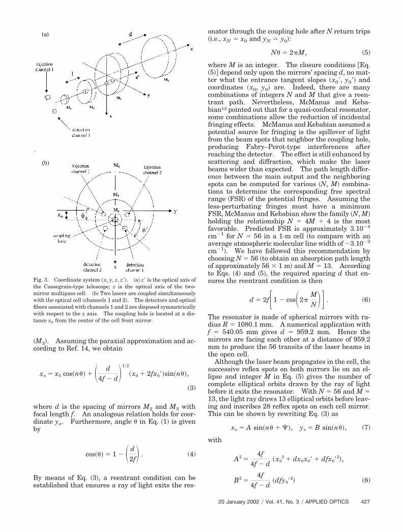
The axis frame �x, y, z� used in this paper to carrythe calculation is illustrated in Fig. 3�a�. A light rayis injected into the resonator with coordinate �x0, y0�and tangent slopes �x0�, y0��. x0 is the position of thecoupling hole in the cell front mirror; we assume y0 isequal to zero. After n transits in the resonator, thelight ray intersects the center plane of a mirror �M2 orM3� at coordinates �xn, yn�.
Points with even numbers n lie on the front mirror�M
2�; points with odd numbers lie on the back mirror
�M3�. Assuming the paraxial approximation and ac-cording to Ref. 14, we obtain
xn � x0 cos�n� � � d4f � d�
1�2
� x0 � 2fx0��sin�n�,
(3)
where d is the spacing of mirrors M2 and M3 withfocal length f. An analogous relation holds for coor-dinate yn. Furthermore, angle in Eq. �1� is givenby
cos�� � 1 � � d2f� . (4)
By means of Eq. �3�, a reentrant condition can beestablished that ensures a ray of light exits the res-
Fig. 3. Coordinate system �x, y, z, z��. �a� z� is the optical axis ofthe Cassegrain-type telescope; z is the optical axis of the two-mirror multipass cell. �b� Two lasers are coupled simultaneouslywith the optical cell �channels 1 and 2�. The detectors and opticalfibers associated with channels 1 and 2 are disposed symmetricallywith respect to the x axis. The coupling hole is located at a dis-tance x0 from the center of the cell front mirror.
onator through the coupling hole after N return trips�i.e., xN x0 and yN y0�:
N � 2�M, (5)
where M is an integer. The closure conditions �Eq.�5� depend only upon the mirrors’ spacing d, no mat-ter what the entrance tangent slopes �x0�, y0�� andcoordinates �x0, y0� are. Indeed, there are manycombinations of integers N and M that give a reen-trant path. Nevertheless, McManus and Keba-bian12 pointed out that for a quasi-confocal resonator,some combinations allow the reduction of incidentalfringing effects. McManus and Kebabian assumed apotential source for fringing is the spillover of lightfrom the beam spots that neighbor the coupling hole,producing Fabry–Perot-type interferences afterreaching the detector. The effect is still enhanced byscattering and diffraction, which make the laserbeams wider than expected. The path length differ-ence between the main output and the neighboringspots can be computed for various �N, M� combina-tions to determine the corresponding free spectralrange �FSR� of the potential fringes. Assuming theless-perturbating fringes must have a minimumFSR, McManus and Kebabian show the family �N, M�holding the relationship N 4M � 4 is the mostfavorable. Predicted FSR is approximately 3.10�4
cm�1 for N 56 in a 1-m cell �to compare with anaverage atmospheric molecular line width of �3.10�2
cm�1�. We have followed this recommendation bychoosing N 56 �to obtain an absorption path lengthof approximately 56 � 1 m� and M 13. Accordingto Eqs. �4� and �5�, the required spacing d that en-sures the reentrant condition is then
d � 2f�1 � cos�2�MN�� . (6)
The resonator is made of spherical mirrors with ra-dius R 1080.1 mm. A numerical application withf 540.05 mm gives d 959.2 mm. Hence themirrors are facing each other at a distance of 959.2mm to produce the 56 transits of the laser beams inthe open cell.
Although the laser beam propagates in the cell, thesuccessive reflex spots on both mirrors lie on an el-lipse and integer M in Eq. �5� gives the number ofcomplete elliptical orbits drawn by the ray of lightbefore it exits the resonator. With N 56 and M 13, the light ray draws 13 elliptical orbits before leav-ing and inscribes 28 reflex spots on each cell mirror.This can be shown by rewriting Eq. �3� as
Equation �5� gives the maximum excursion of thelight ray in the x direction �A� and y direction �B�.Angle � determines the orientation of the ellipse inthe �x, y� plane. With spacing d and focal length fgiven, the entrance tangent slopes �x0�, y0�� and thelocation of the coupling hole �x0� determine the sizeand disposition of the elliptical pattern, according toEqs. �8� and �9�. Moreover, the tangent slopes can beexpressed as
x0� � tan���sin���, y0� � tan���cos���. (10)
� is the off-axis direction of the light ray injected inthe optical cell; as mentioned in Section 2.A, it isdetermined by the focal length of the telescope andthe distance h of the light source from the optical axisof the telescope. Angle � is defined in Fig. 3�b�.Distance h and angle � are used to locate the lightsource at the telescope input.
After N return trips in the cell, the light ray exitsthe cell through the coupling hole; it is collected bythe telescope and focused onto the detector. The po-sition of the detector at the telescope output is givenby distance h� and angle ��. h� is the distance of thedetector from the optical axis of the telescope; angle�� is defined in Fig. 3�b�. According to Ref. 15, thetangent slopes of the light ray exiting the resonatorare given by
x�N�1 �x0
f� x�0, y�N�1 � y�0. (11)
If �� is the off-axis direction of the output beam exit-ing the cell, we can write
By combining Eqs. �11� and �12�, we can easily ex-press �� and �� as functions of x0, x0�, y0�, and f.Then a relation analogous to Eq. �2� allows us toexpress h� according to the radii of curvature R0 andR1 and the spacing of the telescope mirrors. Finally,with distance h� and angle �� obtained, the detectorcan be located properly such that it intercepts theoutput laser beams exiting the telescope.
In designing the optical cell, we proceeded in thefollowing way: Once the reentrant condition wasensured by proper choice of the cell mirrors’ spacing,we computed the entrance tangent slopes and posi-tion of the coupling hole that gives reflex spots widelyspread over the mirror surfaces by means of Eqs.�7�–�9�. With x0�, y0�, and x0 given, we determinefrom Eq. �10� the required entrance off-axis directionand the position of the light source. Then we de-signed the telescope to obtain the needed entranceoff-axis direction by means of Eq. �2�. Finally, the
position of the detector at the output of the telescopewas determined by means of Eqs. �11� and �12�.
3. Practical Construction
A. Optical Arrangement
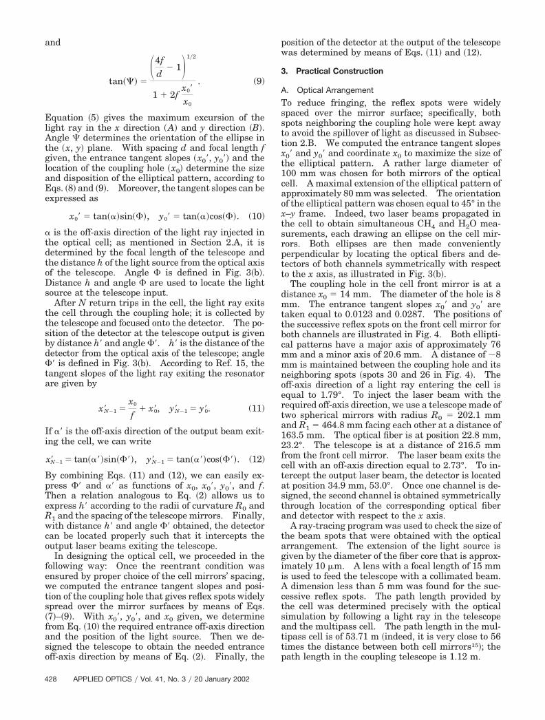
To reduce fringing, the reflex spots were widelyspaced over the mirror surface; specifically, bothspots neighboring the coupling hole were kept awayto avoid the spillover of light as discussed in Subsec-tion 2.B. We computed the entrance tangent slopesx0� and y0� and coordinate x0 to maximize the size ofthe elliptical pattern. A rather large diameter of100 mm was chosen for both mirrors of the opticalcell. A maximal extension of the elliptical pattern ofapproximately 80 mm was selected. The orientationof the elliptical pattern was chosen equal to 45° in thex–y frame. Indeed, two laser beams propagated inthe cell to obtain simultaneous CH4 and H2O mea-surements, each drawing an ellipse on the cell mir-rors. Both ellipses are then made convenientlyperpendicular by locating the optical fibers and de-tectors of both channels symmetrically with respectto the x axis, as illustrated in Fig. 3�b�.
The coupling hole in the cell front mirror is at adistance x0 14 mm. The diameter of the hole is 8mm. The entrance tangent slopes x0� and y0� aretaken equal to 0.0123 and 0.0287. The positions ofthe successive reflex spots on the front cell mirror forboth channels are illustrated in Fig. 4. Both ellipti-cal patterns have a major axis of approximately 76mm and a minor axis of 20.6 mm. A distance of �8mm is maintained between the coupling hole and itsneighboring spots �spots 30 and 26 in Fig. 4�. Theoff-axis direction of a light ray entering the cell isequal to 1.79°. To inject the laser beam with therequired off-axis direction, we use a telescope made oftwo spherical mirrors with radius R0 202.1 mmand R1 464.8 mm facing each other at a distance of163.5 mm. The optical fiber is at position 22.8 mm,23.2°. The telescope is at a distance of 216.5 mmfrom the front cell mirror. The laser beam exits thecell with an off-axis direction equal to 2.73°. To in-tercept the output laser beam, the detector is locatedat position 34.9 mm, 53.0°. Once one channel is de-signed, the second channel is obtained symmetricallythrough location of the corresponding optical fiberand detector with respect to the x axis.
A ray-tracing program was used to check the size ofthe beam spots that were obtained with the opticalarrangement. The extension of the light source isgiven by the diameter of the fiber core that is approx-imately 10 �m. A lens with a focal length of 15 mmis used to feed the telescope with a collimated beam.A dimension less than 5 mm was found for the suc-cessive reflex spots. The path length provided bythe cell was determined precisely with the opticalsimulation by following a light ray in the telescopeand the multipass cell. The path length in the mul-tipass cell is of 53.71 m �indeed, it is very close to 56times the distance between both cell mirrors15�; thepath length in the coupling telescope is 1.12 m.
B. Tolerances
To detect the laser beams, InGaAs photodiodes areused with a large diameter of 1 mm. The light iscollected by means of a large 20-mm diameter focus-ing lens with a focal length of 50 mm. If we take intoaccount the optical arrangement, the source of lightmust be kept within a few tens of microns from thelaser beam’s paraxial position at the focal point of thecollimating lens to maintain the focus of the outputlaser beam on the detector. This process is achievedby using a titanium mechanical mounting that main-tains both the fiber and the collimating lens. Theoptical fiber is connected by means of a standardframe control–physical contact connector. An ap-propriate mechanical adjustment allows us to locatethe optical fiber properly in the �x, y� plane within afew microns of precision. Another cause for losingenergy is an incidental variation of the distance be-tween both cell mirrors. An expansion of less than 1mm of the 1-m cell must be maintained to keep thebeams focused on the detector. Technical solutionsare discussed below. Moreover, the curvature radiiof both mirrors of the open cell must vary within lessthan 1 mm as an effect of the thermal expansion.This variance is achieved through use of zerodur sub-
Fig. 4. Successive laser beam spots over the surface of the cellfront mirror �M2�. After entering the cell, the laser light producesa series of 28 reflex spots lying upon an ellipse on each mirror.Both ellipses, which correspond to the two laser beams propagat-ing simultaneously in the multipass cell, are made perpendicularby means of an appropriate design of the coupling telescope. Af-ter 56 transits in the cell, both laser beams exit the cell through thecoupling hole �spot 56 in the figure� and are collected by the tele-scope, each to be focused on a dedicated detector.
strates. The optical adjustment of the optical cell isobtained by means of fiber red semiconductor lasers.It consists of obtaining the right spacing for the res-onator mirrors that gives the predicted elliptical pat-terns for both channels. The back mirror canpurposely be moved along the cell optical axis. Thenwe adjust the position of the optical fibers by confirm-ing with an infrared sensor card that the output near-infrared laser beams are properly focused on thedetectors and by enhancing the ambient CH4 andH2O absorption signals.
C. Fringing and Detection Limit
As discussed in Subsection 3.A, the laser spots werelargely spread over the 10-cm mirrors to minimizefringing effects. Furthermore, to reduce the numberof successive reflections over each mirror surface, weselected a length of 1 m for the cell to provide the56-m absorption path length. Indeed, the limitednumber of reflections also helps to improve the celltransmittance; assuming a mirror’s reflectance of�97%, a 1-m length leads to a transmittance of 20%,whereas a 0.5-m length would result in a transmit-tance of 3%. The selection of the path length resultsin a compromise between the needed absorption pathlength, the cell transmittance, and the potentialfringing. Regarding the resonator’s mirrors, spher-ical gold-coated mirrors are used �radius, 1080 mm;diameter, 100 mm�. To limit the light scattered bythe mirror surface, we chose highly polished sub-strates �the surface smoothness is less than 0.5 nmrms�; this choice was made possible at low costthrough selection of spherical instead of toroidal mir-rors for the optical design of the Herriott cell. More-over, a tilt misalignment was applied to the detectorsand to the antireflection-coated optics that were usedto couple the fibers with the telescope and to collectthe output laser beams. The beam splitter used totake a reference spectrum at the input of the opticalcell �Fig. 2� is made of properly wedged plates. TheSDLA uses optical fibers to ensure optical connec-tions; throughout the complete optical setup, weavoided fiber-to-fiber connectors and preferred tosplice the various fibers to prevent light from beingreflected at the connections. The achieved opticalcell was revealed to be free of incidental fringing inthe 10�5 absorption range.9 Hence, there is no needto remove the fringing by means of a derivative, fil-tering, or modulation technique10,12 that could com-plexify the instrumental setup or distort themolecular line shape. Direct-differential detectionis used to record the atmospheric spectra, giving ac-cess to the molecular line shape with no distortions;then, by reconstructing the full molecular line shapewith a nonlinear least-squares fit to retrieve the mix-ing ratios, we can monitor atmospheric species overlarge ranges in pressure, temperature, and concen-tration and with a precision error within a few per-cents. The shot-noise-limited dual beam detectormade of two InGaAs photodiode that is used to con-struct a differential spectrum from the signals re-corded at the input and output of the optical cell is
described in Ref. 9. Achieved detection limit is of10�5 absorption units assuming a 300-ms measure-ment time. Figure 5 shows an in situ methane ab-sorption spectrum taken in the stratosphere with theSDLA by differential absorption spectroscopy.
D. Water Vapor Outgassing
A major difficulty associated with the monitoring ofwater vapor in the lower stratosphere is the pollutionof the measurements by the water vapor outgassed bythe instrument itself. The amount of water vapor inthis region of the atmosphere is very low �a few partsper million at 10 hPa�. Hence, as mentioned in theintroduction, the cell is operated open to the atmo-sphere. Furthermore, the optical cell is located 1 munder the main part of the spectrometer �Fig. 1�; itwas made possible by using optical fibers to feed thecell with the laser beams. Moreover, we took carethat no interfering water vapor was mechanicallytrapped along the optical path, followed by the watervapor laser beam, before reaching the open cell.13,16
While installing the open cell in the balloonbornegondola, we took care that no outgassing materials liein its vicinity. The water vapor measurements aretaken at the descent of the gondola in the lowerstratosphere to avoid pollution by the water vapor
Fig. 5. Methane and water vapor absorption spectra obtained wFrance on 10 May 1999. Differential detection was used in conjuat the input �B� and the output �A� of the optical cell are recordedabsorption information �at 17 km, approximately 0.25% of the lasedifferential spectrum from the analogical difference between signathe differential spectrum. The mixing ratio is obtained from a nowith the pressure and temperature measurements and with the HITwas obtained by differential absorption spectroscopy from the sinterference fringes in the 10�5
Fig. 6. Optical multipass cell used with the SDLA. The cell isoptical fibers are connected to the cell to inject the near-infrared lto maintain both gold-coated spherical mirrors of the multipass ce
absorption range.
outgassing from the balloon envelope. The H2O con-centration was taken at night to prevent amplifica-tion of the outgassing process by the sun radiation.Figure 5�d� shows a water vapor absorption spectrumtaken in the stratosphere with the SDLA. A morecomprehensive discussion of the atmospheric watervapor spectroscopy and recent concentration profilesrestituted by the SDLA are given in Refs. 13 and 16.
E. Environmental Conditions and Results
The optical cell is operated open to the atmosphereand thereby is submitted to severe temperature gra-dients during the flight, which could cause opticalmisadjustment by thermal expansion of the cell me-chanical mounting. To minimize thermal expansion�less than 1 mm for a 1-m cell� within a temperaturerange from �30 °C to �80 °C, we use cryogenic Invartubes to maintain both mirrors of the resonator fac-ing each other at a distance of 1 m. The tubes arearranged to form a Serrurier-type mounting that isusual for the large astronomic telescope �see Fig. 6�.The telescope mechanical mounting, the mechanicalinterface used to connect the optical fiber, and themounting of the coupling and collecting lenses aremade of titanium. The weight of the complete opti-cal module is approximately 20 kg. The tempera-
he SDLA in the stratosphere during a balloon flight in southernn with the open multipass cell to obtain the spectra. �a� Spectraarry the intensity calibration. �b� To extract the weak methanergy is absorbed in the cell by ambient methane�, we construct theand B. �c� Methane molecular absorption is then extracted fromar least-squares fit to the full molecular line shape in combination
database. �d� Similarly, the stratospheric water vapor spectrumchannel of the optical cell. Both channels were found free of
ated open to the atmosphere from a stratospheric balloon. Twobeams by means of a small telescope. Invar tubes are combineda distance of approximately 1 m.
ture of the cell mirrors is checked by means ofdedicated thermistors, and flat resistor heaters lo-cated beneath the mirrors are used in avoiding theformation of ice during the flight. Moreover, motor-ized shutters help to prevent the degradation of themirror surfaces at launching and landing or in case ofvery cloudy weather in the lower atmosphere. Theoptical fibers connected to the telescope are protectedwith polyurethane and Mylar sheets to avoid arti-facts that are due to severe temperature change. Tocheck the behavior of the cell during the completeflight, we made sure, while processing the data, thatthere were no incidental artifacts in the in situ spec-tra �unexpected noise, Fabry–Perot fringes, or unex-pected loss in laser energy at the cell output�.Indeed, the SDLA was flown four times from strato-spheric balloons within the period 1998–2000; theopen Herriott cell worked properly during the 3–4-hour flight and revealed to be very robust and insen-sitive to dust, humidity, temperature gradients,vibrations, and shocks �at launching� that are diffi-cult to prevent during field operations. Figure 7shows vertical methane concentration profiles that
Fig. 7. Methane vertical concentration profiles restituted in the10 May 1999. Profiles obtained at ascent and descent of the gondadded to the measurements made during the descent for the sathousand concentration measurements that were obtained througmultipass cell �see Fig. 5�.
were obtained at high spatial resolution while theinstrument was probing the lower stratosphere.
4. Conclusion
The operational capability of an optical multipass cellhas been demonstrated for the in situ monitoring oftrace gas from a stratospheric balloon. ACassegrain-type telescope was used to couple theHerriott-type multipass cell simultaneously with twonear-infrared laser diodes by means of optical fibers.The cell provides an 56-m optical path length and wasfound free of incidental fringing in the 10�5 absorp-tion range. The cell is combined with a direct-differential detection set up to take in situstratospheric and water vapor absorption spectra at1-s intervals in the 10�2 to 10�4 absorption range.The optical cell operated open to the atmosphere wasflown several times from a stratospheric balloon, andits behavior has been fully satisfactory despite thesevere environmental conditions. It made possiblethe achievement of a detection limit of 10�5 absorp-tion units and a inaccuracy of a few percents in the insitu CH and H O concentration measurements in
stratosphere by the SDLA during a flight in southern France one illustrated; a constant offset �equal to 0.3 parts per million� wasclarity. The vertical profiles are made of approximately sevenprocessing of the in situ spectra achieved by means of the open
lowerola arke ofh the
4 2
the stratosphere and thereby the meeting of the sci-ence objectives.
Several members of the technical department ofthe Centre National de la Recherche Scientifique�CNRS�, Institut National des Sciences de l’Univers,Division Technique and of the Service d’Aeronomiewere strongly involved in the design and field opera-tions of the SDLA and are thanked for their veryvaluable assistence: A. Abchiche, N. Amarouche, B.Brient, H. Poncet, J. C. Samake, P. Schibler, and F.Semelin. The research described in this paper hasbeen supported by the Centre National d’Etudes Spa-tiales, the CNRS, and the European Commission.
References1. R. D. May, “Open-path near-IR tunable diode laser spectrom-
eter for atmospheric measurements of H2O,” J. Geophys. Res.103, 19161–19172 �1998�.
2. J. A. Silver and D. C. Hovde, “Near-infrared diode laser air-borne hygrometer,” Rev. Sci. Instrum. 65, 1691–1694 �1994�.
3. K. Uehara and H. Tai, “Remote detection of methane with a1.66-�m diode laser,” Appl. Opt. 31, 809–814 �1992�.
4. C. R. Webster, R. D. May, C. A. Trimble, R. G. Chave, and J.Kendall, “Aircraft �ER-2� laser infrared absorption spectrom-eter �ALIAS� for in situ stratospheric measurements of HCl,N2O, CH4, NO2, and HNO3,” Appl. Opt. 33, 454–472 �1994�.
5. G. W. Harris, G. I. Mackay, T. Iguchi, L. K. Mayne, and H. I.Schiff, “Measurements of formaldehyde in the troposphere bytunable diode laser absorption spectroscopy,” J. Atmos. Chem.8, 119–137 �1998�.
6. G. Toci, P. Mazzinghi, and M. Vannini, “A diode laser spec-trometer for the in situ measurement of the HNO3 content ofpolar stratospheric clouds,” J. Atmos. Ocean. Tech. 16, 1295–1302 �1999�.
7. D. C. Scott, R. L. Herman, C. R. Webster, R. D. May, G. J.Flesh, and E. J. Moyer, “Airborne laser infrared absorptionspectrometer �ALIAS-II� for in situ atmospheric measure-ments of N2O, CH4, CO, HCl, and NO2 from balloon or re-motely piloted aircraft platforms,” Appl. Opt. 38, 4609–4622�1999�.
8. G. Durry and G. Megie, “Atmospheric CH4 and H2O monitor-ing with near-infrared InGaAs laser diodes by the SDLA, aballoonborne spectrometer for tropospheric and stratosphericin situ measurements,” Appl. Opt. 38, 7342–7354 �1999�.
9. G. Durry, I. Pouchet, N. Amarouche, T. Danguy, and G. Megie,“Shot-noise-limited dual-beam detector for atmospheric trace-gas monitoring with near-infrared diode lasers,” Appl. Opt. 39,5609–5619 �2000�.
10. C. R. Webster, “Brewster-plate spoiler: a novel method forreducing the amplitude of interference fringes that limittunable-laser absorption sensitivities,” J. Opt. Soc. Am. B 2,1464–1470 �1985�.
11. J. A. Silver and A. C. Stanton, “Optical interference fringereduction in laser absorption experiments,” Appl. Opt. 27,1914–1916 �1988�.
12. J. B. McManus and P. L. Kebabian, “Narrow optical interfer-ence fringes for certain setup conditions in multipass absorp-tion cells of the Herriott type,” Appl. Opt. 29, 898–900 �1990�.
13. G. Durry and G. Megie, “In situ measurements of H2O from astratospheric balloon by diode laser direct-differential absorp-tion spectroscopy at 1.39 �m,” Appl. Opt. 39, 5601–5608�2000�.
14. D. R. Herriott, H. Kogelnik, and R. Kompfer, “Off-axis paths inspherical mirror interferometers,” Appl. Opt. 3, 523–526�1964�.
15. J. Altmann, R. Baumgart, and C. Weitkamp, “Two-mirror mul-tipass absorption cell,” Appl. Opt. 20, 995–999 �1981�.
16. G. Durry, “Balloonborne near-infrared diode laser spectros-copy for in situ measurements of atmospheric CH4 and H2O,”Spectrochim. Acta Part A 57�9, 1855–1863 �2001�.