ARTICLE Reactivation of dead sulfide species in lithium polysulfide flow battery for grid scale energy storage Yang Jin 1,2,3 , Guangmin Zhou 1 , Feifei Shi 1 , Denys Zhuo 1 , Jie Zhao 1 , Kai Liu 1 , Yayuan Liu 1 , Chenxi Zu 1 , Wei Chen 1 , Rufan Zhang 1 , Xuanyi Huang 1 & Yi Cui 1,4 Lithium polysulfide batteries possess several favorable attributes including low cost and high energy density for grid energy storage. However, the precipitation of insoluble and irrever- sible sulfide species on the surface of carbon and lithium (called “dead” sulfide species) leads to continuous capacity degradation in high mass loading cells, which represents a great challenge. To address this problem, herein we propose a strategy to reactivate dead sulfide species by reacting them with sulfur powder with stirring and heating (70 °C) to recover the cell capacity, and further demonstrate a flow battery system based on the reactivation approach. As a result, ultrahigh mass loading (0.125 g cm –3 , 2 g sulfur in a single cell), high volumetric energy density (135 Wh L –1 ), good cycle life, and high single-cell capacity are achieved. The high volumetric energy density indicates its promising application for future grid energy storage. DOI: 10.1038/s41467-017-00537-0 OPEN 1 Department of Materials Science and Engineering, Stanford University, Stanford, CA 94305, USA. 2 School of Electrical Engineering, Zhengzhou University, Zhengzhou 450001, China. 3 State Key Lab of Electrical Insulation and Power Equipment, School of Electrical Engineering, Xi’an Jiaotong University, Xi’an 710049, China. 4 Stanford Institute for Materials and Energy Sciences, SLAC National Accelerator Laboratory, 2575 Sand Hill Road, Menlo Park, CA 94025, USA. Yang Jin and Guangmin Zhou contributed equally to this work. Correspondence and requests for materials should be addressed to X.H. (email: [email protected]) or to Y.C. [email protected]) NATURE COMMUNICATIONS | 8: 462 | DOI: 10.1038/s41467-017-00537-0 | www.nature.com/naturecommunications 1
Transcript
ARTICLE
Reactivation of dead sulfide species in lithiumpolysulfide flow battery for grid scale energystorageYang Jin1,2,3, Guangmin Zhou1, Feifei Shi1, Denys Zhuo1, Jie Zhao1, Kai Liu1, Yayuan Liu 1, Chenxi Zu1,
Wei Chen1, Rufan Zhang 1, Xuanyi Huang1 & Yi Cui1,4
Lithium polysulfide batteries possess several favorable attributes including low cost and high
energy density for grid energy storage. However, the precipitation of insoluble and irrever-
sible sulfide species on the surface of carbon and lithium (called “dead” sulfide species) leads
to continuous capacity degradation in high mass loading cells, which represents a great
challenge. To address this problem, herein we propose a strategy to reactivate dead sulfide
species by reacting them with sulfur powder with stirring and heating (70 °C) to recover the
cell capacity, and further demonstrate a flow battery system based on the reactivation
approach. As a result, ultrahigh mass loading (0.125 g cm–3, 2 g sulfur in a single cell), high
volumetric energy density (135Wh L–1), good cycle life, and high single-cell capacity are
achieved. The high volumetric energy density indicates its promising application for future
grid energy storage.
DOI: 10.1038/s41467-017-00537-0 OPEN
1 Department of Materials Science and Engineering, Stanford University, Stanford, CA 94305, USA. 2 School of Electrical Engineering, Zhengzhou University,Zhengzhou 450001, China. 3 State Key Lab of Electrical Insulation and Power Equipment, School of Electrical Engineering, Xi’an Jiaotong University,Xi’an 710049, China. 4 Stanford Institute for Materials and Energy Sciences, SLAC National Accelerator Laboratory, 2575 Sand Hill Road, Menlo Park,CA 94025, USA. Yang Jin and Guangmin Zhou contributed equally to this work. Correspondence and requests for materials should be addressed toX.H. (email: [email protected]) or to Y.C. [email protected])
The urgent requirement to develop and integrate renewableenergy such as wind and solar into the grid has driven theintense demand for high energy storage systems for grid
scale energy storage1–3. Electrochemical energy storage, with thebenefits of pollution-free operation, high round-trip efficiency,and flexible power, has been regarded as one of the most effectiveways to solve the problem of intermittent renewable energypenetration4. Commercialized sodium–sulfur (Na–S) batterieshave already been implemented for grid applications to regulatepeak load and frequency, however, it faces a big safety challengedue to its high working temperature (300–350 °C)5. Its high cost(300$ kW h−1) also limits its large-scale application6. Vanadiumredox flow batteries are promising but are still limited by theirlow energy density (< 50Wh kg−1), relatively high cost andenvironmental toxicity7–9. Other systems such as liquid metal
batteries are emerging, is promising but inevitably face the barrierof high working temperature10.
In order to satisfy future large-scale renewable energystorage applications, low cost (<100$ kW h−1), high energydensity (>100Wh kg−1), and safe (room temperature operation)electrochemical energy storage systems are urgently needed6, 11.Lithium–sulfur (Li–S) batteries, with a theoretical energy densityof 2600Wh kg−1, are one of the most promising candidates fornext-generation rechargeable lithium batteries12, 13. However,the low electrical conductivity of sulfur/Li2S, deposition ofnon-soluble and insulating Li2S/Li2S2 on the electrodes, volumechange during cycling, and self-discharge and shuttle effect makeit difficult to move toward industrial application14, 15, especiallyfor high mass loading sulfur electrodes. Many strategies havebeen proposed to control soluble lithium polysulfides including
a
c
Dead Li2Sx(x<4) species Sulfur particleLi2S8 electrolyte
Li
CyclingLi Carbon
felt
Carbonfelt Li
S+Li2Sx Li2Sy(y�4)70°C
Stirring
SulfurLi
After reactivation
Heating
Stirring
RPMHOT
–
+
VBefore reactivation After reactivation
70500
Lithium foil
Carbon felt
Sulfur particle
b
d
Pump
Pump
Battery BatteryHeating and stirring
tank
Li2S8storage tank
Load
Pump
Circulation tube
Battery
Hot plate
Carbonfelt Carbon
felt
°C
Li2S8storage tank
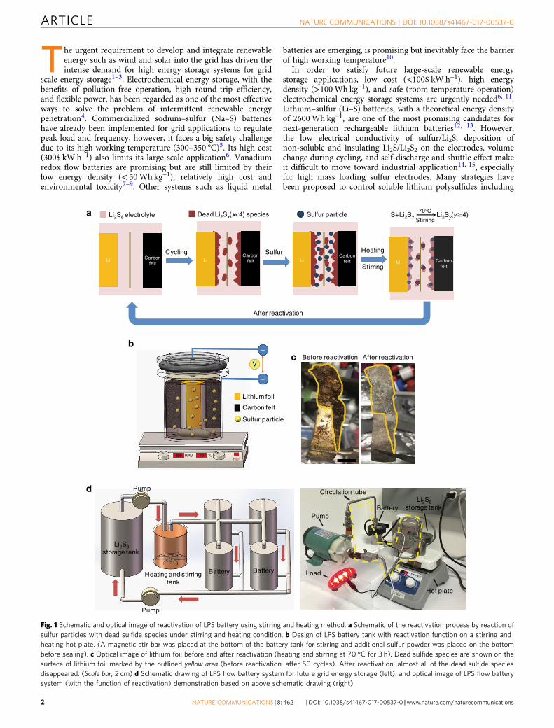
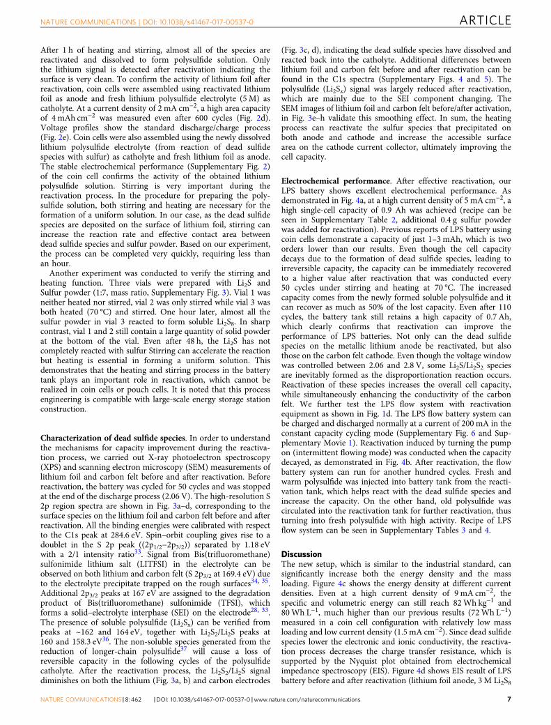
Fig. 1 Schematic and optical image of reactivation of LPS battery using stirring and heating method. a Schematic of the reactivation process by reaction ofsulfur particles with dead sulfide species under stirring and heating condition. b Design of LPS battery tank with reactivation function on a stirring andheating hot plate. (A magnetic stir bar was placed at the bottom of the battery tank for stirring and additional sulfur powder was placed on the bottombefore sealing). c Optical image of lithium foil before and after reactivation (heating and stirring at 70 °C for 3 h). Dead sulfide species are shown on thesurface of lithium foil marked by the outlined yellow area (before reactivation, after 50 cycles). After reactivation, almost all of the dead sulfide speciesdisappeared. (Scale bar, 2 cm) d Schematic drawing of LPS flow battery system for future grid energy storage (left). and optical image of LPS flow batterysystem (with the function of reactivation) demonstration based on above schematic drawing (right)
the design of various carbon–sulfur cathodes or otherarchitectures to confine sulfur16–20, exploration of new electro-lytes or additives21, 22, modification of battery configuration23, 24,and protection of the metallic lithium anode25–27. Although thesestrategies can achieve improved electrochemical performance,these issues have still not been entirely solved, and new directionsfor Li-S batteries are still in development28–30.
Our group previously reported on lithium polysulfide (LPS)semi-liquid battery31, in which liquid polysulfide was used ascathode and metallic lithium as anode, demonstrating highenergy density and compatibility with flow battery design (Sup-plementary Table 1). With the addition of lithium nitrate(LiNO3), a passivation layer will form on the surface of metalliclithium, suppressing parasitic reactions between polysulfide andlithium. No ion-selective membrane was needed thus the cost wasreduced. Most of the characterization of the electrochemicalperformance of LPS batteries were conducted using coin cells,resulting in low mass loading of sulfur, which is not representa-tive of real-world conditions. In the coin cell configuration, it isalso difficult to evaluate the full battery performance and notcompatible with the semi-liquid flow battery concept.
To better realize the high capacity and high mass loading thatare necessary for an industrial set-up, a new battery tank that issuitable for large scale and semi-liquid flow demonstration wasdesigned. During our preliminary high mass loading performancetest, we found that the cell capacity was not stable and decayedvery quickly. After disassembling the battery tank, it wassurprising to find large quantities of insoluble sulfur speciesdeposited on both lithium and cathode (carbon felt) electrodes.These insoluble species result from the low solubility of low-orderpolysulfides like Li2S2/Li2S. As the metallic lithium used in theLPS battery is in excess compared with the quantity of sulfur, theconsumption of metallic lithium reduces the S/Li ratio and causesprecipitation of the insoluble low-order polysulfides. Theseinsoluble sulfide species (Li2Sx, mainly Li2S/Li2S2), called “dead”sulfide species, are inactive and cannot contribute capacity in thefollowing cycles. The conversion of soluble high-order poly-sulfides into insoluble low-order polysulfides (dead sulfide spe-cies) is the main cause of fast capacity decay and finally loss ofelectrochemical activity.
To address the above challenges, herein we propose amethod for the reactivation of dead sulfide species in the cellthrough stirring and heating them with sulfur at a relatively lowtemperature (70 °C). The main idea of reactivation is to useadditional cheap sulfur powder to react with the dead sulfidespecies in order to recover the lost capacity. By virtue of ourbattery tank design, the reactivation process can be implementedwithout disassembling the battery. The single-cell capacity canreach as high as 0.9 Ah with a corresponding volumetric energydensity of 95Wh L−1 (3 M Li2S8), approximately four timeshigher than that of vanadium flow battery (25Wh L−1). Withhigh concentration Li2S8 (5 M), the volumetric energy densitycan reach as high as 135Wh L−1. It is noted that the energydensity and specific energy here are calculated based on thereal cell volume and weight (including polysulfide catholyte,LiNO3 additive, lithium anode, carbon felt, and separator. Thetheoretical and real energy density calculation is presented inSupplementary Notes 1 and 2. Recipe is shown in SupplementaryTable 2). Excellent performance over 110 cycles was attained withreactivation every 50 cycles, demonstrating an ultrahigh massloading of 0.125 g cm−3 (2 g sulfur in single cell). To the best ofour knowledge, this is the first time that such high mass loadingwith stable capacity is reported for LPS batteries, which isdistinctly different from test results derived from coin cells.To further verify the possibility of its practical use in semi-liquidflow systems for future large-scale energy storage, a LPS flow
battery system was successfully demonstrated employing ourbattery tank and reactivation strategy. A capacity of 1 Ah andlong cycle life over 300 cycles are achieved with a reactivationtank connected with the battery system through a circulationpump, which gives a new prospect for low cost, high energydensity, and stable grid scale energy storage.
ResultsLPS battery configuration for reactivation. To address theproblem of dead sulfide species deposition on the lithiumand carbon electrodes, reactivation via heating and stirring at arelatively low temperature (70 °C) was conducted to recycle thedead sulfide species by reacting them with sulfur powder in orderto recover the cell capacity. We hypothesize that such activation ispossible since it is similar to how we prepare polysulfide solutionby using Li2S and sulfur powder mixed in ether solvent at elevatedtemperature28, 31. This approach has two obvious benefits—cheapsulfur powder can be used to increase the capacity while alsoremoving the dead sulfide species from the surface of the elec-trodes. The process is illustrated in Fig. 1a. After prolongedcycling, dead Li2Sx deposits on both the surface of the lithium foiland the carbon felt. Then the cell was moved to a hot plate withheating and stirring functions (Fig. 1b), the stirring rate here was500 RPM for stable and homogeneously stirring (this rate isvariable according to the battery tank size and stirring bar size).The dead sulfide species react with sulfur during heating andstirring and convert to soluble high-order polysulfides, like Li2S8,Li2S6, and Li2S4, thus becoming reactivated and increasing the cellcapacity. Based on our design, the sulfur added was sufficient forreactivation, and the dead sulfide species were mainly converted toLi2S8, while Li2S6 and Li2S4 also exist due to the equilibrium in theelectrolyte. It was apparent that coin cell or pouch cell config-urations used in previous research was not suitable for demon-strating the reactivation concept so to verify the above effect inLPS battery, a new battery configuration was therefore designedfor high mass loading tests. As shown in Fig. 1b, a stainless steeltank was made for cell assembly (optical image of different sizedtanks in Supplementary Fig. 1). The positive and negative sideswere electrically insulated from one another by a Polytetra-fluoroethylene (PTFE) spacer and the whole battery tank wassealed with a silicone rubber O-ring and a plastic crimp. Lithiumfoil was used as the anode and liquid lithium polysulfide solutionwas selected as catholyte using carbon felt as the current collector.The lithium foil, wrapped by a separator, was fixed on the negativebar with a snap joint structure to ensure good electrical contact.The separator here was used for electrical insulation of the carbonfelt current collector from the lithium foil, which differs from theseparator used in specially designed redox battery using expensiveion-selective membranes. The sealing requirement is not strict asthe working temperature is low and no pressure is applied to thecontainer. In contrast, the cost of LPS batteries here will be largelyreduced, making it a good candidate for large-scale applications.For reactivation under stirring and heating condition, a magneticstir bar was placed on the bottom of the tank. After configuringthe carbon felt and lithium foil, lithium polysulfide (Li2S8) solutionin 1,3-dioxolane (DOL)/1,2-dimethoxyethane (DME) was injectedinto the battery tank. Before sealing the battery, some additionalsulfur powder was added to the bottom of the tank for futurereactivation. As the polysulfide is in its highest order state,the additional sulfur on the bottom will not turn into solublepolysulfide, and is thus stored in the tank for future reactivation.The main idea of reactivation is to activate the dead sulfide species(Li2Sx) on the lithium foil anode and carbon matrix cathode inorder to recover its original capacity. When cycling at high massloading of polysulfide caltholyte, dead sulfide species are easily
deposited on the surface of lithium foil, as shown in Fig. 1c (left).The dark-red sulfide species is a mixture of Li2Sx compounds.These insulating species will block ion and electron transport andquickly deteriorate the capacity and stability of the LPS battery.
After reactivation, as shown in Fig. 1c (right), nearly all of thedead sulfide species were removed and the lithium foil surface isrefreshed. The reactivation process not only increases the cellcapacity, but also reduces the impedance of the battery thusenhancing the cell stability. Based on the outlined new cellconfiguration design, a high performance LPS battery was achieved.
LPS flow battery with reactivation function was designed basedon a new battery configuration. Figure 1d (left) shows a schematicof the LPS flow battery system. The whole energy storage systemcan be divided into three parts: polysulfide storage tank, heatingand stirring tank, and battery tank. The flow battery system canwork in two modes: continuous flow working mode andintermittent flow working mode. In the continuous mode, thepump remains on and the polysulfide electrolyte continuously
flows through the battery tank. The dead sulfide species on thelithium foil and solid precipitates on the carbon felt currentcollector can be re-dissolved or reactivated with the flowingpolysulfide solution. The stirring and heating tank helps toreactivate the dead sulfide species and solid precipitates. As forthe intermittent flow working mode, the pump alternates betweenthe on and off state. After a certain period of cycling, the pump isturned on to initiate the reactivation process and inject freshpolysulfide solution. Intermittent flow working mode may bemore suitable for practical application as the pump consumesfewer additional electricity.
To further demonstrate the LPS flow battery system, a realsystem was set up using the battery tank described above tosimulate this mode. As shown in Fig. 1d (right), the whole systemincludes electrolyte storage tank, battery tank, circulation tube,magnetic circulation pump, hot plate with stirring function, andload (e.g., bike light). The electrolyte storage tank was placed onthe hot plate and served as the polysulfide reactivation and
0 1 2 3 4 5 61.6
1.8
2.0
2.2
2.4
2.6
2.8
10th
100th
200th
400th
600th
0 100 200 300 400 500 6000
2
4
6
8
10
12
14
0.5
0.6
0.7
0.8
0.9
1.0
100 200 300 400 500 600
Before reactivation
After reactivation
a
bBefore After
Are
a ca
paci
ty (
mA
h cm
–2)
Cou
lom
bic
effic
ienc
y
Cycle number
2 mA cm–2
Area capacity (mAh cm–2)
Vol
tage
(V
)
d e
Wave number (cm–1)In
tens
ity (
a.u.
)
cLi
Li2Sx(2<x<4)
Li2S/Li2S2
0 min 5 min 15 min 60 min
DOL/DME
Sulfur
Lithium foil
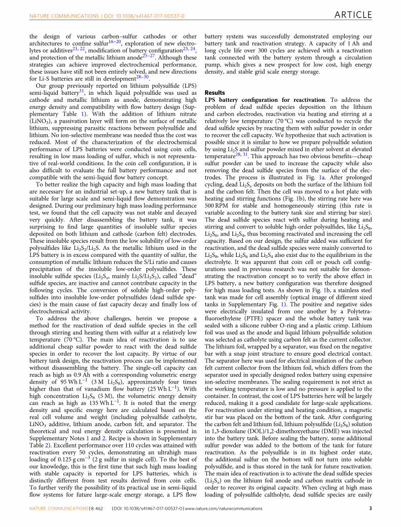
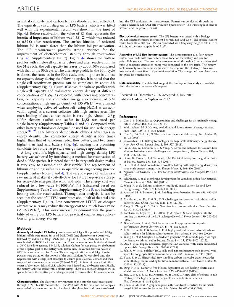
Fig. 2 Dead sulfide species reaction with sulfur powder. a Optical images of dead sulfide species on the surface of lithium foil after reaction with sulfurpowder in DOL/DME electrolyte under stirring and heating (70 °C) condition to form polysulfides after 0, 5, 10, and 60min. b Optical images of lithium foilbefore and after dead sulfide species reaction with sulfur powder. (Scale bar, 2 cm) c Raman measurement of lithium foil before and after dead sulfidespecies reaction with sulfur powder. d Electrochemical performance of lithium foil (after reactivation) with 5M LPS catholyte. e Voltage profiles of lithiumfoil (after reactivation) with 5M LPS catholyte
storage vessel. The battery tank was assembled with carbon felt,lithium foil, and separator. Fresh and warm polysulfides can beinjected into the battery tank through the pump, and the deadsulfide species can be reactivated in the storage tank understirring and heating condition.
Dead sulfide species reacting with sulfur powder. To furtherconfirm the reaction of dead sulfide species with sulfur powderunder stirring and heating condition, sulfide species evolutionexperiments were conducted by stirring and heating lithium foildeposited with dead sulfide species in DOL/DME electrolyte with
sulfur powder. As shown in Fig. 2a, a bottle of DOL/DME (1:1)electrolyte with a small amount of sulfur powder (300 mg) addedat the bottom was placed on a hot plate heating at 70 °C in anargon-filled glove box (H2O< 0.1 ppm and O2< 0.1 ppm). Thenthe lithium foil with dead sulfide species on the surface wasimmersed into the electrolyte. After stirring and heating, the deadsulfide species dissolved into the electrolyte and the colorbecomes darker and darker. About 1 h later, the solid dead sulfidespecies were nearly all dissolved and the electrolyte becomes darkred. Then the lithium foil was taken out and washed with DOL toremove liquid polysulfide on the surface. No obvious solid pre-cipitates are observed in the electrolyte solution (Fig. 2a,
174 172 170 168 166 164 162 160 1580
50
100
150
200
250
300
350
400S 2pTFSI
SEILi2Sx
Li2S2
174 172 170 168 166 164 162 160 1580
50
100
150
200
250
300
350
400
SEI
TFSI S 2p
174 172 170 168 166 164 162 160 1580
50
100
150
200
250
300
350
400
450
SEI
TFSIS 2p
174 172 170 168 166 164 162 160 1580
50
100
150
200
250
300
350
400
450S 2p
SEI
TFSI
Lithium foil before
Lithium foil after
Carbon felt after
e
f
g
h
Carbon felt before
a
b
c
d
Inte
nsity
(a.
u.)
Inte
nsity
(a.
u.)
Inte
nsity
(a.
u.)
Inte
nsity
(a.
u.)
Binding energy
Binding energy
Binding energy
Binding energy
Li2Sx
Li2S2
Li2S
Li2S2
Li2Sx
Li2Sx
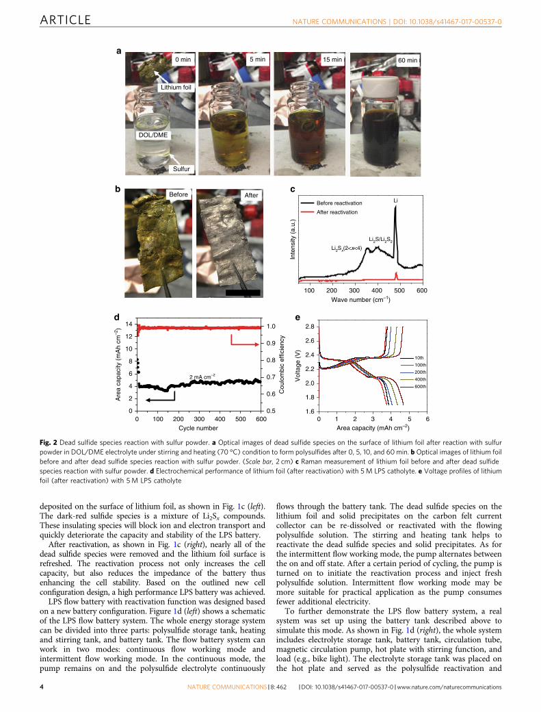
Fig. 3 Characterization of dead sulfide species. a–d XPS analysis before and after reactivation: a, b lithium foil, c, d carbon felt. S2p spectra are presented, includingpeak deconvolution and assignments. e–h SEM images before and after reactivation: e, f lithium foil (scale bar, 100 μm), g, h carbon felt (scale bar, 50 μm)
60 min). Figure 2b shows the optical image of lithium before andafter reaction with sulfur powder. It is clear that nearly all thedead sulfide species were removed and the surface is refreshedand shining. The lithium foil remains intact and no obviouscorrosion or deformation is noted. Further evidence is providedwhen lithium foil was immersed in high concentration polysulfide
solution for a long time (the lithium foil used in this experimentwas taken from a battery running for almost 4 months) and themorphology remains unchanged (Fig. 2b). Figure 2c shows theRaman measurement of lithium foil before and after reactivation.It demonstrates that there are Li2S2/Li2S and Li2Sx (2< x< 4)species32 on the surface of the lithium foil before reactivation.
020406080
100120140160
0 2 4 6 8 100
20406080
100120140
Wh kg–1
Wh L–1
Wh kg–1
Wh L–1
0 50 100 150 200 250 3000.0
0.2
0.4
0.6
0.8
1.0
1.2
1.4
1.6
Pump on for 5 s Pump on for 5 s
Cycle number
Cel
l cap
acity
(A
h)
Pump off Pump off Pump off
a
0 1 2 3 4 5 6 70.0
0.5
1.0
1.5
2.0
2.5
3.0Before reactivationAfter reactivation
Re(z) (ohm)
–Im
(z)
(ohm
)
dc
Current density (mA cm–2)
Ene
rgy
dens
ity
0.0 0.2 0.4 0.6 0.8 1.0 1.22.0
2.2
2.4
2.6
2.8
2nd10th20th50th
51st60th
Cell capacity (Ah)
eV
olta
ge (
V)
2.02.12.22.32.42.52.62.72.8
1.81.61.41.21.00.80.60.40.20
0 1851651451251058525 45
2 M Li2S8
3 M Li2S8
5 M Li2S8
65
Vol
tage
(V
)
Cell capacity (Ah)
Volumetric energy density (Wh L–1)
LPS
VanadiumRedox
Lead Acid
NickelHydrogen
ZincBromine
f
b
Ene
rgy
dens
ity
g
R2 R1 W1 R3
CPE1 CPE2
0 10 20 30 40 50 60 70 80 90 100 1100.0
0.2
0.4
0.6
0.8
1.0
1.2
1.4
1.6
0
20
40
60
80
100
ReactivationReactivation
Cycle number
Cel
l cap
acity
(A
h)
Cou
lom
bic
effic
ienc
y (
%)
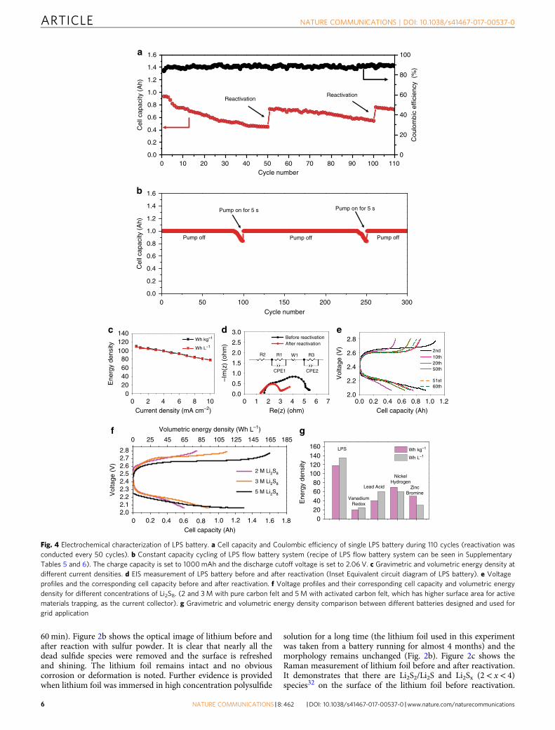
Fig. 4 Electrochemical characterization of LPS battery. a Cell capacity and Coulombic efficiency of single LPS battery during 110 cycles (reactivation wasconducted every 50 cycles). b Constant capacity cycling of LPS flow battery system (recipe of LPS flow battery system can be seen in SupplementaryTables 5 and 6). The charge capacity is set to 1000mAh and the discharge cutoff voltage is set to 2.06 V. c Gravimetric and volumetric energy density atdifferent current densities. d EIS measurement of LPS battery before and after reactivation (Inset Equivalent circuit diagram of LPS battery). e Voltageprofiles and the corresponding cell capacity before and after reactivation. f Voltage profiles and their corresponding cell capacity and volumetric energydensity for different concentrations of Li2S8. (2 and 3M with pure carbon felt and 5M with activated carbon felt, which has higher surface area for activematerials trapping, as the current collector). g Gravimetric and volumetric energy density comparison between different batteries designed and used forgrid application
After 1 h of heating and stirring, almost all of the species arereactivated and dissolved to form polysulfide solution. Onlythe lithium signal is detected after reactivation indicating thesurface is very clean. To confirm the activity of lithium foil afterreactivation, coin cells were assembled using reactivated lithiumfoil as anode and fresh lithium polysulfide electrolyte (5 M) ascatholyte. At a current density of 2 mA cm−2, a high area capacityof 4 mAh cm−2 was measured even after 600 cycles (Fig. 2d).Voltage profiles show the standard discharge/charge process(Fig. 2e). Coin cells were also assembled using the newly dissolvedlithium polysulfide electrolyte (from reaction of dead sulfidespecies with sulfur) as catholyte and fresh lithium foil as anode.The stable electrochemical performance (Supplementary Fig. 2)of the coin cell confirms the activity of the obtained lithiumpolysulfide solution. Stirring is very important during thereactivation process. In the procedure for preparing the poly-sulfide solution, both stirring and heating are necessary for theformation of a uniform solution. In our case, as the dead sulfidespecies are deposited on the surface of lithium foil, stirring canincrease the reaction rate and effective contact area betweendead sulfide species and sulfur powder. Based on our experiment,the process can be completed very quickly, requiring less thanan hour.
Another experiment was conducted to verify the stirring andheating function. Three vials were prepared with Li2S andSulfur powder (1:7, mass ratio, Supplementary Fig. 3). Vial 1 wasneither heated nor stirred, vial 2 was only stirred while vial 3 wasboth heated (70 °C) and stirred. One hour later, almost all thesulfur powder in vial 3 reacted to form soluble Li2S8. In sharpcontrast, vial 1 and 2 still contain a large quantity of solid powderat the bottom of the vial. Even after 48 h, the Li2S has notcompletely reacted with sulfur Stirring can accelerate the reactionbut heating is essential in forming a uniform solution. Thisdemonstrates that the heating and stirring process in the batterytank plays an important role in reactivation, which cannot berealized in coin cells or pouch cells. It is noted that this processengineering is compatible with large-scale energy storage stationconstruction.
Characterization of dead sulfide species. In order to understandthe mechanisms for capacity improvement during the reactiva-tion process, we carried out X-ray photoelectron spectroscopy(XPS) and scanning electron microscopy (SEM) measurements oflithium foil and carbon felt before and after reactivation. Beforereactivation, the battery was cycled for 50 cycles and was stoppedat the end of the discharge process (2.06 V). The high-resolution S2p region spectra are shown in Fig. 3a–d, corresponding to thesurface species on the lithium foil and carbon felt before and afterreactivation. All the binding energies were calibrated with respectto the C1s peak at 284.6 eV. Spin–orbit coupling gives rise to adoublet in the S 2p peak ((2p1/2−2p3/2)) separated by 1.18 eVwith a 2/1 intensity ratio33. Signal from Bis(trifluoromethane)sulfonimide lithium salt (LITFSI) in the electrolyte can beobserved on both lithium and carbon felt (S 2p3/2 at 169.4 eV) dueto the electrolyte precipitate trapped on the rough surfaces34, 35.Additional 2p3/2 peaks at 167 eV are assigned to the degradationproduct of Bis(trifluoromethane) sulfonimide (TFSI), whichforms a solid–electrolyte interphase (SEI) on the electrode28, 33.The presence of soluble polysulfide (Li2Sx) can be verified frompeaks at ~162 and 164 eV, together with Li2S2/Li2S peaks at160 and 158.3 eV36. The non-soluble species generated from thereduction of longer-chain polysulfide37 will cause a loss ofreversible capacity in the following cycles of the polysulfidecatholyte. After the reactivation process, the Li2S2/Li2S signaldiminishes on both the lithium (Fig. 3a, b) and carbon electrodes
(Fig. 3c, d), indicating the dead sulfide species have dissolved andreacted back into the catholyte. Additional differences betweenlithium foil and carbon felt before and after reactivation can befound in the C1s spectra (Supplementary Figs. 4 and 5). Thepolysulfide (Li2Sx) signal was largely reduced after reactivation,which are mainly due to the SEI component changing. TheSEM images of lithium foil and carbon felt before/after activation,in Fig. 3e–h validate this smoothing effect. In sum, the heatingprocess can reactivate the sulfur species that precipitated onboth anode and cathode and increase the accessible surfacearea on the cathode current collector, ultimately improving thecell capacity.
Electrochemical performance. After effective reactivation, ourLPS battery shows excellent electrochemical performance. Asdemonstrated in Fig. 4a, at a high current density of 5 mA cm−2, ahigh single-cell capacity of 0.9 Ah was achieved (recipe can beseen in Supplementary Table 2, additional 0.4 g sulfur powderwas added for reactivation). Previous reports of LPS battery usingcoin cells demonstrate a capacity of just 1–3 mAh, which is twoorders lower than our results. Even though the cell capacitydecays due to the formation of dead sulfide species, leading toirreversible capacity, the capacity can be immediately recoveredto a higher value after reactivation that was conducted every50 cycles under stirring and heating at 70 °C. The increasedcapacity comes from the newly formed soluble polysulfide and itcan recover as much as 50% of the lost capacity. Even after 110cycles, the battery tank still retains a high capacity of 0.7 Ah,which clearly confirms that reactivation can improve theperformance of LPS batteries. Not only can the dead sulfidespecies on the metallic lithium anode be reactivated, but alsothose on the carbon felt cathode. Even though the voltage windowwas controlled between 2.06 and 2.8 V, some Li2S/Li2S2 speciesare inevitably formed as the disproportionation reaction occurs.Reactivation of these species increases the overall cell capacity,while simultaneously enhancing the conductivity of the carbonfelt. We further test the LPS flow system with reactivationequipment as shown in Fig. 1d. The LPS flow battery system canbe charged and discharged normally at a current of 200 mA in theconstant capacity cycling mode (Supplementary Fig. 6 and Sup-plementary Movie 1). Reactivation induced by turning the pumpon (intermittent flowing mode) was conducted when the capacitydecayed, as demonstrated in Fig. 4b. After reactivation, the flowbattery system can run for another hundred cycles. Fresh andwarm polysulfide was injected into battery tank from the reacti-vation tank, which helps react with the dead sulfide species andincrease the capacity. On the other hand, old polysulfide wascirculated into the reactivation tank for further reactivation, thusturning into fresh polysulfide with high activity. Recipe of LPSflow system can be seen in Supplementary Tables 3 and 4.
DiscussionThe new setup, which is similar to the industrial standard, cansignificantly increase both the energy density and the massloading. Figure 4c shows the energy density at different currentdensities. Even at a high current density of 9 mA cm−2, thespecific and volumetric energy can still reach 82Wh kg−1 and80Wh L−1, much higher than our previous results (72Wh L−1)measured in a coin cell configuration with relatively low massloading and low current density (1.5 mA cm−2). Since dead sulfidespecies lower the electronic and ionic conductivity, the reactiva-tion process decreases the charge transfer resistance, which issupported by the Nyquist plot obtained from electrochemicalimpedance spectroscopy (EIS). Figure 4d shows EIS result of LPSbattery before and after reactivation (lithium foil anode, 3 M Li2S8
as initial catholyte, and carbon felt as cathode current collector).The equivalent circuit diagram of LPS battery, which was fittedwell with the experimental result, was shown in the inset ofFig. 4d. Before reactivation, the value of R1 that represents theinterfacial impedance of lithium was 1.321Ω, which was reducedto 0.52Ω after reactivation. The surface kinetics of activatedlithium foil is much faster than the lithium foil pre-activation.The EIS measurement provides strong evidence for theimprovement of electrochemical stability through reactivation(Fig. 4d, Supplementary Fig. 7). Figure 4e shows the voltageprofiles with single-cell capacity before and after reactivation. Inthe 51st cycle, the cell capacity increases by about 50% comparedwith that of the 50th cycle. The discharge profile in the 60th cycleis almost the same as in the 50th cycle, meaning there is almostno capacity decay during the following cycles. It is noted that thesingle-cell reactivation process can be completed in about 2 h(Supplementary Fig. 8). Figure 4f shows the voltage profiles withsingle-cell capacity and volumetric energy density at differentconcentrations of Li2S8. As expected, with increasing concentra-tion, cell capacity and volumetric energy also increase. At 5Mconcentration, a high energy density of 135Wh L−1 was attainedwhen employing activated carbon felt (using NaOH as an acti-vation agent) as a current collector with high surface area. Themass loading of each concentration is very high. About 1–2.6 gsulfur element (sulfur and sulfur in Li2S) was used persingle battery (Supplementary Tables 5 and 6). Compared withother battery technologies designed or used for grid scale energystorage38, 39, LPS batteries demonstrate obvious advantages inenergy density. The volumetric energy density is four timeshigher than that of vanadium redox flow battery, and two timeshigher than lead acid battery (Fig. 4g), making it a promisingcandidate for future large-scale energy storage applications.
A long cycle life, high capacity, and high energy density LPSbattery was achieved by introducing a method for reactivation ofdead sulfide species. It is noted that the battery tank design makesit very easy to assemble and disassemble. The replacement oflithium or adding sulfur is also operable in engineering practice(Supplementary Notes 3 and 4). The very low price of sulfur as araw material makes it cost-effective for future large-scale storagefor renewable energies like wind and solar. The energy cost wasreduced to a low value (< 100$ kW h−1) (calculated based onSupplementary Table 7 and Supplementary Note 5, not includingheating cost for reactivation). Through cost analysis, it can beseen that the cost of LITFSI contributes about half of the total cost(Supplementary Fig. 9). Low concentration LITFSI or cheaperalternative salts may reduce the energy cost to a much lower value(< 50$ kW h−1). This work successfully demonstrates the possi-bility of using our LPS battery for practical engineering applica-tion in grid energy storage.
MethodsAssembly of single LPS battery. An amount of 1.4 g sulfur powder and 0.28 glithium sulfide were mixed in 16ml DOL/DME (1:1) electrolyte in a 20ml vial,followed by addition of 0.5 g LiNO3 and 1.5 g LITFSI. The LiNO3 and LITFSIwere heated at 110 °C for 2 days before use. Then the solution was heated and stirredat 70 °C for 6 h to generate 3M Li2S8 solution. Carbon felt was placed on the bottomof the negative part of the battery tank. Before use, the carbon felt was heated at60 °C in a vacuum oven for 2 days. Then a magnetic stir bar and 0.4 g of sulfurpowder were placed on the bottom of the tank. Lithium foil was fixed onto thenegative bar with a snap joint structure to ensure good electrical contact and thenwrapped with commercial separator (Celgard 2250). Lithium foil was set into thecenter of the carbon felt and Li2S8 solution was injected into the battery tank. Finally,the battery tank was sealed with a plastic crimp. There is a specially designed PTFEspacer between the positive part and negative part to insulate them from one another.
Characterization. The electronic environment of the samples were investigatedthrough XPS (Phi5000 VersaProbe, Ulvac-Phi) with Al Kα radiation. All sampleswere sealed in a vacuum transfer chamber in the glove box and then transferred
into the XPS equipment for measurement. Raman was conducted through theHoriba Scientific LabRAM HR Evolution Spectrometer. The wavelength of laser is532 nm and the power is 5 mW.
Electrochemical measurement. The LPS battery was tested with a BiologicEC-Lab Electrochemistry instrument between 2.06 and 2.8 V. The applied currentvaries from 20 to 200 mA. EIS was conducted with frequency range of 100 kHz to0.1 Hz, at the sinus amplitude of 5 mV.
Assemble of LPS flow battery system. The demonstration LPS flow batterysystem was made with two battery tanks (one for the battery and one forpolysulfide storage). The two tanks were connected through a 6 mm stainless steeltube. A magnetic circulation pump was connected to the two tanks. The batterytank assembly was the same as the above battery, and the electrolyte tank wasinjected with about 48 mL of polysulfide solution. The storage tank was placed on ahot plate for reactivation.
Data availability. The data that support the findings of this study are availablefrom the authors on reasonable request.
Received: 14 December 2016 Accepted: 6 July 2017
References1. Chu, S. & Majumdar, A. Opportunities and challenges for a sustainable energy
future. Nature 488, 294–303 (2012).2. Whittingham, M. S. History, evolution, and future status of energy storage.
Proc. IEEE 100, 1518–1534 (2012).3. Chu, S., Cui, Y. & Liu, N. The path towards sustainable energy. Nat. Mater. 16,
16–22 (2016).4. Soloveichik, G. L. Battery technologies for large-scale stationary energy storage.
Ann. Rev. Chem. Biomol. Eng. 2, 503–527 (2011).5. Lu, X., Xia, G., Lemmon, J. P. & Yang, Z. Advanced materials for sodium-beta
alumina batteries: status, challenges and perspectives. J. Power Sources 195,2431–2442 (2010).
6. Dunn, B., Kamath, H. & Tarascon, J. M. Electrical energy for the grid: a choiceof battery. Science 334, 928–935 (2011).
7. Li, L. et al. A stable vanadium redox-flow battery with high energy density forlarge-scale energy storage. Adv. Energy Mater. 1, 394–400 (2011).
8. Nguyen, T. & Savinell, R. F. Flow batteries. Electrochem. Soc. Interface 19, 54–56(2010).
9. Schwenzer, B. et al. Membrane development for vanadium redox flow batteries.ChemSusChem 4, 1388–1406 (2011).
10. Wang, K. et al. Lithium-antimony-lead liquid metal battery for grid-levelenergy storage. Nature 514, 348–350 (2014).
11. Armand, M. & Tarascon, J. M. Building better batteries. Nature 451, 652–657(2008).
12. Manthiram, A., Fu, Y. & Su, Y. S. Challenges and prospects of lithium sulfurbatteries. Acc. Chem. Res. 46, 1125–1134 (2013).
13. Yang, Y., Zheng, G. & Cui, Y. Nanostructured sulfur cathodes. Chem. Soc. Rev.42, 3018–3032 (2013).
14. Barchasz, C., Lepretre, J. C., Alloin, F. & Patoux, S. New insights into thelimiting parameters of the Li/S rechargeable cell. J. Power Sources 199, 322–330(2012).
15. Demir-Cakan, R. et al. Li–S batteries: simple approaches for superiorperformance. Energy Environ. Sci. 6, 176–182 (2013).
16. Ji, X. L., Lee, K. T. & Nazar, L. F. A highly ordered nanostructured carbon-sulfur cathode for lithium-sulfur batteries. Nat. Mater. 8, 500–506 (2009).
17. Wang, C. et al. Slurryless Li2S/reduced graphene oxide cathode paper for high-performance lithium sulfur battery. Nano. Lett. 15, 1796–1802 (2015).
18. Qiu, Y. et al. Highly nitridated graphene-Li2S cathodes with stable modulatedcycles. Adv. Energy Mater. 5, 1501369 (2015).
19. Seh, Z. W. et al. Sulphur-TiO2 yolk-shell nanoarchitecture with internal voidspace for long-cycle lithium-sulfur batteries. Nat. Commun. 4, 1331 (2013).
20. Yuan, Z. et al. Hierarchical free-standing carbon nanotube paper electrodeswith ultrahigh sulfur loading for lithium-sulfur batteries. Adv. Funct. Mater. 24,6105–6112 (2014).
21. Ding, F. et al. Dendrite-free lithium deposition via self-healing electrostaticshield mechanism. J. Am. Chem. Soc. 135, 4450–4456 (2013).
22. Suo, L., Hu, Y. S., Li, H., Armand, M. & Chen, L. A new class of solvent-in-saltelectrolyte for high-energy rechargeable metallic lithium batteries.Nat. Commun. 4, 1481 (2013).
23. Zhou, G. M. et al. A graphene-pure-sulfur sandwich structure for ultrafast,long-life lithium-sulfur batteries. Adv. Mater. 26, 625–631 (2014).
24. Li, Z., Zhang, J. T., Chen, Y. M., Li, J. & Lou, X. W. Pie-like electrode design forhigh-energy density lithium-sulfur batteries. Nat. Commun. 6, 8850 (2015).
25. Zu, C. & Manthiram, A. Stabilized lithium metal surface in a polysulfide-richenvironment of lithium sulfur batteries. J. Phys. Chem. Lett. 5, 2522–2527(2014).
26. Li, W. et al. The synergetic effect of lithium polysulfide and lithium nitrate toprevent lithium dendrite growth. Nat. Commun. 6, 7436 (2015).
27. Lu, Y., Tu, Z. & Archer, L. Stable lithium electro deposition in liquid andnanoporous solid electrolytes. Nat. Mater. 13, 961–969 (2014).
28. Ren, Y. X., Liu, M., Zhao, T. S., Zeng, L. & Wu, M. C. An aprotic lithium/polyiodide semi-liquid battery with an ionic shield. J. Power Sources 342, 9–16(2017).
29. Dong, K., Wang, S. & Yu, J. A lithium/polysulfide semi-solid rechargeable flowbattery with high output performance. RSC Adv. 4, 47517–47520 (2014).
30. Zhang, S. S. & Read, J. A. A new direction for the performance improvement ofrechargeable lithium/sulfur batteries. J. Power Sources 200, 77–82 (2012).
31. Yang, Y., Zheng, G. & Cui, Y. A membrane-free lithium/polysulfide semi-liquidbattery for large-scale energy storage. Energy Environ. Sci. 6, 1552–1558 (2013).
32. Hagen, M. et al. In-situ Raman investigation of polysulfide formation in Li-Scells. J. Electrochem. Soc. 160, A1205–A1214 (2013).
33. Vizintin, A. et al. Fluorinated reduced graphene oxide as an interlayer in Li-Sbatteries. Chem. Mater. 27, 7070–7081 (2015).
34. Dedryver̀e, R. et al. XPS valence characterization of lithium salts as a tool tostudy electrode/electrolyte interfaces of Li-ion batteries. J. Phys. Chem. B. 110,12986–12992 (2006).
35. Moulder, J. F. & Chastain, J. Handbook of X-ray Photoelectron Spectroscopy: AReference Book of Standard Spectra for Identification and Interpretation of XPSData (Perkin-Elmer, Physical Electronics Division, 1992).
36. Yan, J. H. et al. High-performance lithium-sulfur batteries with a cost-effectivecarbon paper electrode and high sulfur-loading. Chem. Mater. 27, 6394–6401(2015).
37. Barchasz, C. et al. Lithium/sulfur cell discharge mechanism: an originalapproach for intermediate species identification. Anal. Chem. 84, 3973–3980(2012).
38. Skyllas-Kazacos, M., Chakrabarti, M. H., Hajimolana, S. A., Mjalli, F. S.& Saleem, M. Progress in flow battery research and development.J. Electrochem. Soc. 158, R55–R79 (2011).
39. Linden, D. Handbook of Batteries and Fuel Cells (McGraw-Hill, 1984).
AcknowledgementsThis work was supported by the Joint Center for Energy Storage Research (JCESR), abattery hub under US Department of Energy.
Author contributionsY.C. conceived the project. Y.J. and G.Z. assembled the batteries and performed thebattery tests. X.H. performed small cell fabrication and testing. F.S., J.Z., K.L. and Y.Lperformed the characterization. All authors analyzed the data and contributed to thediscussion. Y.J., G.Z., F.S. and Y.C. wrote the manuscript.
Additional informationSupplementary Information accompanies this paper at doi:10.1038/s41467-017-00537-0.
Competing interests: The authors declare no competing financial interests.
Reprints and permission information is available online at http://npg.nature.com/reprintsandpermissions/
Publisher's note: Springer Nature remains neutral with regard to jurisdictional claims inpublished maps and institutional affiliations.
Open Access This article is licensed under a Creative CommonsAttribution 4.0 International License, which permits use, sharing,
adaptation, distribution and reproduction in any medium or format, as long as you giveappropriate credit to the original author(s) and the source, provide a link to the CreativeCommons license, and indicate if changes were made. The images or other third partymaterial in this article are included in the article’s Creative Commons license, unlessindicated otherwise in a credit line to the material. If material is not included in thearticle’s Creative Commons license and your intended use is not permitted by statutoryregulation or exceeds the permitted use, you will need to obtain permission directly fromthe copyright holder. To view a copy of this license, visit http://creativecommons.org/licenses/by/4.0/.