24
| Date post: | 15-Jul-2015 |
| Category: |
Software |
| Upload: | kaliyaperumal-krishnan |
| View: | 560 times |
| Download: | 5 times |
AGENDA
Introduction to SDN
Introduction to OFP
OF Switch components
OF Ports
OF Tables
OF Channel

SDN INTRODUCTION
In the SDN architecture, the control and data
planes are decoupled, network intelligence
and state are logically centralized, and the
underlying network infrastructure is
abstracted from the applications.
- ONF white paper

LIMITATION OF CURRENT NETWORKING…
Complexity of current static network
Server virtualization
IP converged network for video, data and audio
Inconsistent policies
Inability to scale
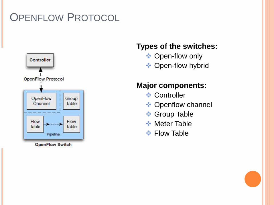
OPENFLOW PROTOCOL
Types of the switches:
Open-flow only
Open-flow hybrid
Major components:
Controller
Openflow channel
Group Table
Meter Table
Flow Table

PORTS
Open flow ports:
Network interfaces for passing packets between Openflow Processing and the rest of the Network
Openflow switches connected through Openflow ports
Types:
Physical ports
Switch defined ports
Eg. Physical ports map one to one Ethernet interfaces
Logical Ports
switch defined ports that don’t correspond to a hardware interface of switch
Logical ports include “Tunnel-ID”.
Reserved Ports
defined by ONF 1.3.1
specify generic forwarding actions such as sending to the controller, flooding and forwarding using non-openflow methods

RESERVED PORT TYPES
ALL represents all ports the switch can use for forwarding a specific port
can be used only as output interface
CONTROLLER represents the control channel with the open flow controller
can be used as ingress (packet-out) and egress (packet-in)
TABLE represents the start of the openflow pipeline
used for control packets generated by the switch
IN-PORT represents packet ingress port
ANY special values used in openflow command when no port is specified
can neither be used as ingress nor egress
LOCAL used for switch local networking and its management stack
NORMAL represents the traditional non-openflow pipeline of the switch
FLOOD flooding using normal pipeline of the switch on all the ports except the incoming port
and the port which is in blocked state

TABLES Openflow Tables
Allows to have multiple flow tables and each would have n
number of flow entries
Group Table Only one Group table
Group multiple flow entries to point to a group
Meter Table
Only one Meter table
Used for shaping the traffic

OPENFLOW TABLES Pipeline processing
Start at the first FT and may be redirected to another FT, actions would be updated by each matching FE
Go only in forward direction not backward
If packet is not redirected to another FT then pipeline processing stops and the packet is processed with associated actions set.
Flow Table Match field, Priority, Counters, Instructions and Timeouts
Matching Packet type, packet headers, src MAC, dest IP
Matching with multiple entries – choose based on priority
Apply-actions
Table-miss Table-miss FE added by the controller
Priority is 0
Can be dropped, fwd to next FT, fwd to controller
Flow removal Requested by the controller
Timer expiry ( hard timeout timer, idle time out timer)

PIPELINE PROCESSING
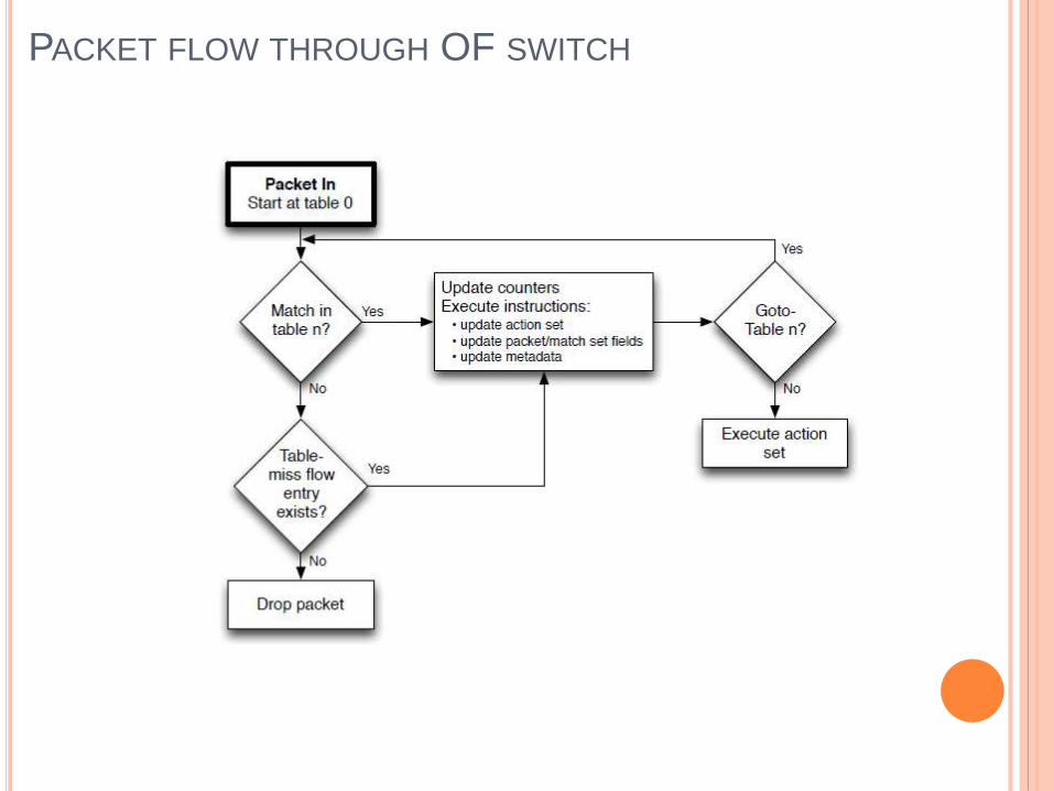
PACKET FLOW THROUGH OF SWITCH
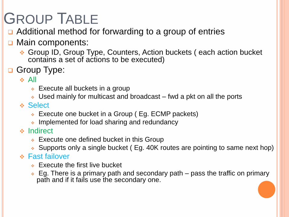
GROUP TABLE Additional method for forwarding to a group of entries
Main components: Group ID, Group Type, Counters, Action buckets ( each action bucket
contains a set of actions to be executed)
Group Type: All
Execute all buckets in a group
Used mainly for multicast and broadcast – fwd a pkt on all the ports
Select Execute one bucket in a Group ( Eg. ECMP packets)
Implemented for load sharing and redundancy
Indirect Execute one defined bucket in this Group
Supports only a single bucket ( Eg. 40K routes are pointing to same next hop)
Fast failover Execute the first live bucket
Eg. There is a primary path and secondary path – pass the traffic on primary path and if it fails use the secondary one.
METER TABLE Consists of meter entries and defining per-flow meters
Per-flow meters enable OF to implement QoS operations (rate-limiting)
Components of Meter table:
Meter ID, Meter Band, Counters
Meters measures the rate of packets assigned to it and enable controlling the rate of those packets
Meters are attached directly to flow entries
Meter band: unordered list of meter bands, where each meter band specifies the rate of the band and the way to process packet
Components of Meter band:
Band Type, Rate, Counters, Type specific arguments
Band Type : defined how to process a packet (drop/ dscp remark)
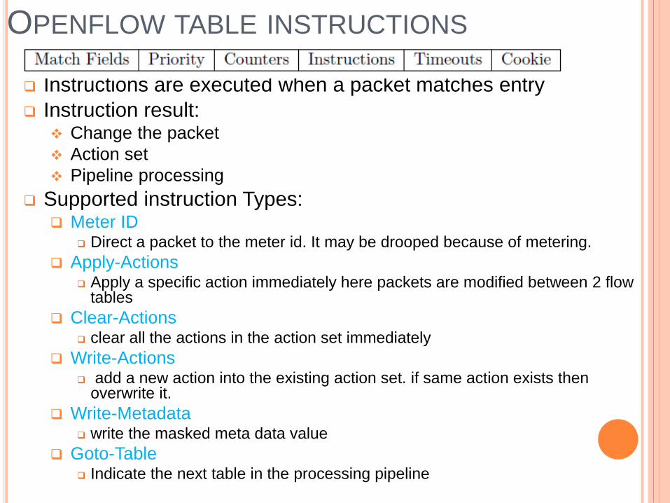
OPENFLOW TABLE INSTRUCTIONS
Instructions are executed when a packet matches entry
Instruction result: Change the packet
Action set
Pipeline processing
Supported instruction Types: Meter ID
Direct a packet to the meter id. It may be drooped because of metering.
Apply-Actions Apply a specific action immediately here packets are modified between 2 flow
tables
Clear-Actions clear all the actions in the action set immediately
Write-Actions add a new action into the existing action set. if same action exists then
overwrite it.
Write-Metadata write the masked meta data value
Goto-Table Indicate the next table in the processing pipeline

ACTION SET
Action set is associated with each packet
FE modify the action set using write-action/ clear-action
Actions in the action-set will be executed when pipeline is stopped
Action set contains maximum of one action of each type
If multiple actions of the same type need to be added then use “Apply-Actions”
Need to follow the below order to execute action
Different Types of Action Set: Copy TTL inwards – apply copy inward actions to the packet
Pop – apply all tag pop actions to the packet
Push MPLS – apply MPLS tag push action to the packet
Push PBB – apply PBB tag push action to the packet
Copy TTL outwards
Decrement TTL
Set – apply set field actions to the packet
QoS
Group – apply group actions
Output – forward a packet on the port specified by the output action

ACTION LIST
“Apply-action” , “packet-out” messages include action list
Execute an action immediately
Actions are executed sequentially in the order they have been specified
If action list contains an output action, a copy of the packet is forwarded in its current state to the desired port
Action-set shouldn’t be changed because of action-list
ACTION
What to do with the packet when match criteria matches with the packet
Some of the Action Type:
Output Fwd a pkt to the specified open flow port (physical/ logical/reserved)
Set Queue Set Queue-id of the port : determines which queue should be used for
scheduling and forwarding packet
Drop Packets which doesn’t have output action should be dropped
Group Process the packet through specified group
Push-Tag/ Pop-Tag Insert VLAN, MPLS, PBB tage
Set-Field Rewriting a field in the packet header
Change TTL Decrement TTL
OPENFLOW CHANNEL Message:
Controller-to-switch message
Asynchronous message
Symmetric message
Controller to Switch Message: Feature request/reply
Controller request the switch about its capability
Configuration request/reply Query the switch configuration
Modify-State Add/delete/modify entries in the flow table
Read-State Collect various info from the switch such as config, statistics
Packet-Out Controller informs switch to fwd a packet on a specific interface
Reply to “packet-in”
Barrier Controller uses this to make sure message dependencies are met
Role-Request To set the role of its openflow channel/ query that role
Asynchronous configuration Set a filter an asynchronous message it receives from switch

ASYNCHRONOUS MESSAGE
Sent by switch to the controller to denote packet arrival,
switch state change or error
Types:
Packet-in
Packet needs to be processed by the controller will be sent as packet-in
Eg. Table miss, TTL checking
Switch can store the packet in the buffer and send only the buffer-ID along
with the header ( default 128 bytes – it is configurable)
Buffer would expire after a period of interval
Flow Removal
Once flow entry is deleted by a Switch when any one of the timer expiry,
switch would inform the controller
Port Status
When port admin state/ protocol state is changed to down
Error
Switch would send an error message if it not able to process a message
which was sent by a controller

SYMMETRIC MESSAGE
Hello
Exchange information between switch and controller when
switch comes up
Controller learns about switch from Hello packet
Echo
Echo request/reply messages can be sent from either the
switch or the controller, and must return an echo reply.
They are mainly used to verify the liveness of a controller-
switch connection
Experimenter
Used for future/testing purpose

OPENFLOW CHANNEL CONNECTION
Connection setup
TLS/ TCP connection
Version should match
Connection interruption
Failure secure mode
Drop all the message destined to the controller
Flow entries would automatically expire
Failure standalone mode
Will act as a legacy switch
Encryption
Controller and switch authenticate each other
OPENFLOW CHANNEL CONNECTION
Multiple controller
For load-balancing and redundancy
Role:
EQUAL:
All controllers have read and write permission on the switch
MASTER-SLAVE:
only one Master and all are slave
Master have read and write access but all slaves can only read
When master goes down, election would happen and any of them cane
be selected as a Master
Once master is selected, the switch has to send error message to the
other/ old Master
Generation id – identifies a given mastership view

OPENFLOW CHANNEL CONNECTION
Auxiliary connection
Created by switch for better performance and parallelism
Openflow channel can composed of a main connection and multiple
auxiliary connections
Connection from switch to the controller are identified by
Data path id + Auxiliary ID
Data path id would be same for all
Auxiliary id is 0 for main connection and non-zero for others
Auxiliary connections could be created only if main connection is
established
Each Aux connection uses their different transport (TCP, TSL ports) but
source IP and destination IP should be same
There is no difference between main connection and aux connections
If Main connection goes down, all aux connection should be brought
down
Message reordering is not supported – can use Barrier message

THANK YOU


