256
VF-09-99-A2 OPERA-2D REFERENCE MANUAL Vector Fields Limited 24 Bankside Kidlington Oxford OX5 1JE England

VF-09-99-A2
OPERA-2D REFERENCE MANUAL
Vector Fields Limited24 Bankside
KidlingtonOxford OX5 1JE
England

2
Copyright © 1999 by Vector Fields Limited, England
This document was prepared using Adobe® FrameMaker®.
UNIX is a trademark of X/Open Company LtdHPGL is a trademark of Hewlett-Packard Incorporated
PostScript is a trademark of Adobe Systems IncorporatedWindows 95/98/NT is a trademark of Microsoft Corporation
OpenVMS and Alpha are trademarks of Compaq Computer CorporationX Window System is a trademark of Massachusetts Institute of Technology
All other brand or product names are trademarks or registered trademarks of their respective companies or organisations.
OPERA-2d Reference Manual 27 September 1999
CONTENTS
. 1-1
. 1-3
. 2-1
. 2-2
. 2-9
2-10
. 2-11
2-13
2-15
2-19
2-20
2-22
2-23
2-34
2-35
. 3-1
Chapter 1 System Overview
Introduction .........................................................................................
Program Limits ...................................................................................
Chapter 2 User Interface
Introduction .........................................................................................
The Graphical User Interface ..............................................................
Keyboard Input ...................................................................................
Output Files ........................................................................................
Commands and Parameters ...............................................................
The Help Character ! ................................................................. 2-12
Parameter Assignment .......................................................................
Parameter Values ................................................................................
Command Interpreter Errors ..............................................................
Confidence Level ...............................................................................
Prompted free format Input ................................................................
Built-in Commands ............................................................................
Command Separator and Comments .................................................
Euler Angles ......................................................................................
Chapter 3 The Pre and Post-Processor
Introduction .........................................................................................
OPERA-2d Reference Manual Version 7.1
2 CONTENTS
... 3-3
3-10
-19
-20
-24
-25
-28
-29
-31
-32
-36
-37
-39
-41
-43
-66
-71
-72
-74
-81
-82
83
-91
106
109
12
116
117
121
123
125
128
130
140
141
144
146
147
The Pre and Post-Processor Quick Reference Guide ........................
Using Expressions ..............................................................................
The APPEnd Command .................................................................. 3
The BHDAta Command ................................................................... 3
The CHECk Command .................................................................... 3
The CIRCle Command ..................................................................... 3
The CLEAr Command ...................................................................... 3
The COLOur Command ................................................................... 3
The COMOutput Command ............................................................ 3
The CONTour Command ................................................................. 3
The CONVert Command .................................................................. 3
The COPY Command ...................................................................... 3
The DEVIce Command .................................................................... 3
The DIMEnsion Command .............................................................. 3
The DRAW Command ..................................................................... 3
The DUMP Command ...................................................................... 3
The DXFOutput Command .............................................................. 3
The EDIT Command ........................................................................ 3
The EMIT Command ........................................................................ 3
The END Command ......................................................................... 3
The ERASe Command .................................................................... 3
The EXTErnal Circuit Command .................................................... 3-
The EXTRa Command ..................................................................... 3
The GRAPh Command .................................................................. 3-
The GROUp Command ................................................................. 3-
The HARMonics Command .......................................................... 3-1
The HELP Command ..................................................................... 3-
The INTArea Command ................................................................. 3-
The INTCircle Command ............................................................... 3-
The INTLine Command .................................................................. 3-
The LINE Command ....................................................................... 3-
The MESH Command .................................................................... 3-
The MODIfy Command .................................................................. 3-
The PAN Command ........................................................................ 3-
The PLOT Command ..................................................................... 3-
The POINt Command ..................................................................... 3-
The PRINt Command ..................................................................... 3-
The READ Command .................................................................... 3-
OPERA-2d Reference Manual Version 7.1
3
49
153
157
164
166
168
169
172
173
176
178
182
183
-185
The RECOnstruct Command ........................................................ 3-1
The SET Command ........................................................................ 3-
The SOLVe Command .................................................................... 3-
The SYMMetry Command ............................................................. 3-
The TEST Command ..................................................................... 3-
The TITLe Command ..................................................................... 3-
The TRACk Command ................................................................... 3-
The UNDO Command .................................................................... 3-
The UNITs Command ..................................................................... 3-
The VECTor Command .................................................................. 3-
The VIEW Command ..................................................................... 3-
The WRITe Command .................................................................... 3-
The ZOOM Command .................................................................... 3-
Graphical User Interface Reference ................................................ 3
Version 7.1 OPERA-2d Reference Manual
4 CONTENTS
OPERA-2d Reference Manual Version 7.1

Chapter 1System Overview
of an theevel-
ppli-t theme of
ithent
of
e ofili-ele-
eri-
Introduction
This manual describes the OPERA-2d Pre and Post-Processor, onesuite of finite element based programs which can be used as tools idesign of electromagnetic devices of all kinds. OPERA-2d has been doped for use on PC’s and workstations by Vector Fields Limited.
OPERA-2d solves a wide range of electromagnetic and electrostatic acations in 2-dimensional xy and axisymmetric coordinates. At presensuite comprises a pre and post-processor, 9 analysis programs (sowhich are optional extras) and a DXF file translation program.
Pre and Post-Processor
• OPERA-2d/PP: interactive pre and post-processor.
Static Fields • OPERA-2d/ST: magnetostatic and electrostatic field analysis, wnon-linear materials. ST includes software to adapt the finite elemmesh in order to achieve a specified accuracy.
• OPERA-2d/SP: electrostatic field analysis including the effectsspace charge created by beams of particles.
Eddy Currents • OPERA-2d/AC: steady-state ac eddy current analysis, including usnon-uniform permeabilities from OPERA-2d/ST, complex permeabties and external circuits. AC includes software to adapt the finite ment mesh in order to achieve a specified accuracy.
• OPERA-2d/TR: transient eddy current analysis, with non-linear matals, multiple drives, background dc fields and external circuits.
OPERA-2d Reference Manual Version 7.1
1-2 Chapter 1 - System Overview
r-VLve a
tor
tro-
her-olu-
n
Post-hical
sed to
lysisthe
• OPERA-2d/VL: uniform linear or rotational motion induced eddy curent analysis, where the topology does not change with time. includes software to adapt the finite element mesh in order to achiespecified accuracy.
Rotating Machines
• OPERA-2d/RM: transient analysis of rotating machines, with a rohaving a fixed speed of rotation, and all the features of TR.
Stress and Thermal
• OPERA-2d/SA: stress analysis using forces calculated from elecmagnetic solutions.
• OPERA-2d/TH and OPERA-2d/THTR: steady-state and transient tmal analysis using ohmic heating calculated from electromagnetic stions.
Utility • OPERA-2d/DXF: A program which translates a DXF file to aOPERA-2d command input file.
The following chapters of this Reference Manual describe the Pre and Processor in detail. Chapters 2 describes the Command Line and GrapUser Interfaces and Chapter 3 describes the commands which are uprepare data for and process the results from the analysis programs.
More information on how to use the pre and post-processor and anaprograms, including worked examples and tutorials, is given in OPERA-2d User Guide.
OPERA-2d Reference Manual 27 September 1999
Program Limits 1-3
ofessor.
e:
vail-
d by
ith
Program Limits
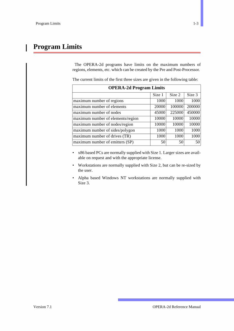
The OPERA-2d programs have limits on the maximum numbersregions, elements, etc. which can be created by the Pre and Post-Proc
The current limits of the first three sizes are given in the following tabl
• x86 based PCs are normally supplied with Size 1. Larger sizes are aable on request and with the appropriate license.
• Workstations are normally supplied with Size 2, but can be re-sizethe user.
• Alpha based Windows NT workstations are normally supplied wSize 3.
OPERA-2d Program Limits
Size 1 Size 2 Size 3maximum number of regions 1000 1000 1000maximum number of elements 20000 100000 200000maximum number of nodes 45000 225000 450000maximum number of elements/region 10000 10000 10000maximum number of nodes/region 10000 10000 10000maximum number of sides/polygon 1000 1000 1000maximum number of drives (TR) 1000 1000 1000maximum number of emitters (SP) 50 50 50
Version 7.1 OPERA-2d Reference Manual
1-4 Chapter 1 - System Overview
OPERA-2d Reference Manual 27 September 1999
Chapter 2User Interface
rfaceUser
com- fea- fullbse-tions,
put and
Introduction
The interactive pre and post-processor of OPERA-2d has a user intewhich comprises a command line interface as well as a Graphical Interface (GUI).
The GUI generates text commands which have the same syntax as themands which can be typed in directly at the keyboard. There are sometures which can be used only from the keyboard. This chapter givesdetails of how to use the GUI and the command line interface. In suquent chapters, the keyboard commands are described with indicawhere appropriate, of the corresponding GUI interaction.
Within this manual, different fonts are used to differentiate between inand output of various types. The program’s commands, parameterskeywords are shown in sans-serif font; input and output from theprogram in bold and normal weight teletype font . File namesare shown in a slanted font. GUI items are shown in a narrow teletypefont .
OPERA-2d Reference Manual Version 7.1

2-2 Chapter 2 - User Interface
on-put
are:
on the
s to andthat
eys:
indi-
p-
the
The Graphical User Interface
The GUI is built from 8 types of input window which are selected and ctrolled by pointing with the cursor and clicking a mouse button. Some inwindows accept characters typed at the keyboard. The input windows
• Horizontal menu: Only used for top level menu.
• Vertical menu: For selecting commands and options.
• ParameterBox: For entering numerical or character data.
• DialogBox: Combination of text inputs and switches.
• FileBox: For selection of files.
• CDBox: For selection of current directory or folder.
• ColourBox: For re-defining colours.
The GUI also uses MessageBoxes to display messages and questionsdisplay.
Menus
Menus are horizontal or vertical lists of keywords which indicate actionbe performed. Menu items are selected by pointing with the mouseclicking its left button. When the mouse is pointing at a menu item, item is highlighted.
Alternatively, menu items can be chosen using the keyboard arrow k← and → for a horizontal menu or ↑ and ↓ for a vertical menu. When therequired item is highlighted, it can be selected using the <Enter> ,<Return> or ↵ keys.
Selecting a menu item can have one of several effects; the action iscated by a symbol at the right-hand side of the item:
Symbol Action
↓ Drop Down: this activates a sub-menu. It only exists in the tolevel horizontal menu. Pull Right: activates a sub-menu.
Pick and Pull: activates a sub-menu after a selection from displayed model (see Pick below). Return: returns to higher-level menu.
OPERA-2d Reference Manual 27 September 1999

The Graphical User Interface 2-3
s. Ifevel
sibleesh.
until
ey-
gh-first
ges
is-
ice
des
he
o-lefttheiteer-
ionse
The <Esc > key can be used to escape from a menu without any actionthe menu does not allow Pick operations, selecting from a higher lmenu can also be used to close it.
Not all menu items can be used at all times. For example, it is not posto execute post-processing commands if there is no solution or no mUnavailable menu items are displayed in pale-blue rather than white they become available as the result of other commands.
Parameter Boxes
ParameterBoxes (figure 2.1) are used to input information from the k
board. Default values (if they exist) are displayed and are initially hilighted. When a value is highlighted it can be replaced by the
Toggle: swaps between 2 options and the symbol chan
between and . The current state of the program is dplayed. Option: chooses one from a set of options. The current cho
is indicated by (filled with red).
Pick: must be followed by a selection from the displayemodel. This is done by positioning the cursor (which chang
shape to+) over the required part of the model and pressing tleft mouse button. Rubber-box: must be followed by selection of diagonally oppsite corners of a rectangle. This is done by pressing the mouse button with the cursor at one corner and dragging mouse, with the button held down, releasing it at the opposcorner. The menus are automatically hidden while the rubbbox is being used. Action: executes a command or requests additional informatvia a ParameterBox or both; sometimes the menu will cloafter the specified action.
Figure 2.1 A Typical ParameterBox
Symbol Action (continued)
Minimum X coordinate = 0Maximum X coordinate = 10Minimum Y coordinate = 0Maximum Y coordinate = 10
Accept Dismiss
Version 7.1 OPERA-2d Reference Manual
2-4 Chapter 2 - User Interface
efore
hete oraram-
and
ted.
rit-les.
ar isfilet ofrtion
leftne
characters typed. A value can be edited by moving the text cursor btyping any characters keys.
Most ParameterBoxes have and below tlist of parameters. These can be selected with the mouse to execuescape from the command. The mouse can also be used to identify a peter to be edited.
Editing parameter values and controlling the execution of the commcan be achieved with the following keys:
• ↑, ↓ and <Tab> can be used to move between the parameters.
• ← and → move the text cursor within the value being edited.
• <Enter> , <Return> or ↵ move to next parameter. If is highlighted or there is only one parameter, the command is execu
• <Esc> escapes from the command.
• <Back-space> or <Delete> delete characters.
• To toggle insert mode: <Insert> (Windows) or function keys <F2>or <PF2> (X-windows)
• To move to start of the value <Home> (Windows) or function keys<F3> or <PF3> (X-windows)
• To move to end of the value: <End> (Windows) or function keys <F4>or <PF4> (X-windows)
FileBoxes and CDBoxes
FileBoxes (figure 2.2) are used for selecting a file name for reading or wing. The FileBox contains a filter string which specifies a subset of all fiIf the filter is edited, it can be acted on by typing <Enter> , <Return>
or ↵ or by selecting the button.
If there are more files than can be displayed in the FileBox a scroll-bdisplayed at the left side of the list of names. Similarly, if the longest name is too long for the FileBox a scroll bar is displayed below the lisnames. The size of the slider within the scroll bar indicates the propoof the text which is displayed. The text can be scrolled in two ways:
• clicking above or below the slider in the vertical scroll bar, or to the or right of the slider in the horizontal scroll bar, scrolls the text by opage in the direction indicated.
Accept Dismiss
Accept
Filter
OPERA-2d Reference Manual 27 September 1999

The Graphical User Interface 2-5
hilethe
ing the
heed by
aren be file
ping
irec-ile-
UItedewping as
n ben-
• dragging the slider, by pressing and holding the left mouse button wmoving the mouse scrolls the text in the direction indicated while mouse is moving.
One file should be selected from the list of files. Double-clicking (selectthe file twice in quick succession) confirms the selection. Alternatively,
selection can be confirmed by selecting the button. Trequired file name can also be typed into the selection box and accepttyping <Enter> , <Return> or ↵.
The current directory or folder name is shown and its sub-directoriesalso displayed in a second selection area. The current directory cachanged by using a double-click selection in the same way as for aname, or by typing the directory name into the selection box and ty<Enter> , <Return> or ↵. Any change of directory in a FileBox isremembered for the next time the FileBox is used, unless the current dtory is changed using the CDBox which resets the directories for all FBoxes.
The CDBox implements the Change Directory command within the G(seepage 2-32). It displays a list of subdirectories, which can be selecby double-click or typing in the same way as within the FileBox. If the ndirectory includes a disk or device name, it can only be selected by tythe full name into the selection box. When the current directory is
required, the CDBox can be closed with the button.
In FileBoxes and CDBoxes, file tree-names and directory names cagiven using environment variables (UNIX and Windows only). Enviro
Figure 2.2 A File Selection Box
File Selection BoxFilter*.*
Files in: /u/guest
mot10.meshmot10.op2mot10.st mot20.meshmot20.op2mot20.st mot30.meshmot30.op2mot30.st
Sub-directories
.. ex4_23
Selected file
Selected directory
Accept Filter CD Dismiss
Accept
Quit
Version 7.1 OPERA-2d Reference Manual
2-6 Chapter 2 - User Interface
f the
ey-
ndcted
lueeter-
ofput
lect- off
ectedcted
tedd to
msld be
ationxt on
ared by
ment variables $VFDIR (on UNIX systems) and %VFDIR% (on Win-dows systems) are defined by the software as the parent directory osoftware.
DialogBoxes
DialogBoxes are used to input information using a combination of kboard and mouse operations. Within a DialogBox there can be:
• Text-inputs: black rectangles. Initially the first text-input is selected aany characters typed will appear there. Any text-input can be selewith the mouse before typing. The <Enter> , <Return> , ↵, ↓ or<Tab> keys can be used to move to the next text-input. The ↑ key canbe used to move to the previous text input. Within a text-input the vacan be edited using the editing and function keys defined for Param
Boxes (seepage 2-3). Selecting a down arrow button to the right a text input activates a FileBox to supply a file name for the text-in(see page 2-4).
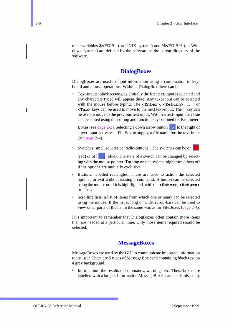
• Switches: small squares or ‘radio-buttons’. The switches can be on
(red) or off (blue). The state of a switch can be changed by seing with the mouse pointer. Turning on one switch might turn othersif the options are mutually exclusive.
• Buttons: labelled rectangles. These are used to action the seloptions, or exit without issuing a command. A button can be seleusing the mouse or, if it is high-lighted, with the <Enter> , <Return>or ↵ key.
• Scrolling lists: a list of items from which one or many can be selecusing the mouse. If the list is long or wide, scroll-bars can be useview other parts of the list in the same was as for FileBoxes (page 2-4).
It is important to remember that DialogBoxes often contain more itethan are needed at a particular time. Only those items required shouselected.
MessageBoxes
MessageBoxes are used by the GUI to communicate important informto the user. There are 5 types of MessageBox each containing black tea grey background.
• Information: the results of commands, warnings etc. These boxeslabelled with a large i. Information MessageBoxes can be dismisse
OPERA-2d Reference Manual 27 September 1999

The Graphical User Interface 2-7
oll-dowtherp or
badancelled
ard
.d by
thears has
eted.ted dis-
om-
play.e, a
ons,
the
andountce
col-
typing any key on the keyboard (except <F1>) or with the left mousebutton.
• If the quantity of information exceeds the size of the window, a scrbar is displayed to enable the whole message to be viewed. The winwill show the top of the message as the scroll is generated, but oparts of the message can be viewed by dragging the scroll bar udown.
• Errors: these include Pick operations outside the model space andvalues in ParameterBoxes. The program gives the user another chto perform the input if an error occurs. Error MessageBoxes are labewith a large !. They can be dismissed by typing any key on the keybo(except <F1>) or with the left mouse button.
• Questions: these always require a choice between and QuestionBoxes are labelled with a large ?. They can be dismisse
selecting either the box or the box.
• Input: these always require additional information to be given by user via a ParameterBox, a DialogBox or a FileBox which appebelow the MessageBox. The boxes disappear when the informationbeen supplied.
• Timer: these indicate how much of an operation has been complTimers are only displayed for operations for which the estimaelapsed time is greater than 5 seconds. Timer boxes cannot bemissed, but will automatically disappear when the operation is cplete.
ColourBoxes
The ColourBox (figure 2.3) is used to redefine colours used on the disIt consist of 3 horizontal slider bars, one each for red, green and blusquare showing the colour as it is changed and three butt
, and .
The colour can be adjusted by moving the sliders in two ways:
• clicking to the left or right of the slider decreases or increasesamount of a colour by 10%.
• dragging a slider by pressing and holding the left mouse button moving the mouse to the left or right decreases or increases the amof a colour while the mouse is moving in proportion to the distanbetween the cursor and the slider.
The buttons a colour by changing the display to use the
YES NO
YES NO
Accept Cancel Quit
Accept
Version 7.1 OPERA-2d Reference Manual

2-8 Chapter 2 - User Interface
col-
the
il the
icture
nd
our in the colour square; the changes by restoring the
our to what it was when the ColourBox was opened; and ColourBox.
Note that on some types of display, the new colours are not shown untpicture is redrawn.
Hiding and Leaving the Menus
Sometimes it is necessary to hide the menus so that the complete pcan be seen. This can be done using the <F1> function key. bring themenus back again.
To leave the menus completely the top-level menu item should be selected. To return to menu-mode, the keyboard comma^should be given. (This is the caret character followed by <Enter> ,<Return> or ↵.)
Figure 2.3 A ColourBox
Colour Change
Red 0 100%90%
Green 0 100% 0%
Blue 0 100% 0%
Colour 4
Apply Cancel Quit
Cancel
Quit
MENU-OFF
OPERA-2d Reference Manual 27 September 1999

Keyboard Input 2-9
tion,. At
ich is
d orither
is isdow
er aped,
Keyboard Input
A typical keyboard input consists of a command to perform some actogether with parameters that determine how the action is performedother times the input is a list of ‘free-format’ keywords or numbers whprovide additional input to an earlier command. Keyboard inputrequested by a prompt of the form
name >
where name is the name of the program or program section being usesometimes is a question to be answered. Alphabetic input can be in eupper or lower case.
Even in keyboard mode, some commands require graphical input. Thprovided by positioning the cross-shaped cursor on the graphics winand typing a key on the keyboard or a mouse button.
Some commands are ‘built-into’ the command interpreter. Whenevprompt of the form given above is issued, built-in commands can be tyby starting the input line with $.
Version 7.1 OPERA-2d Reference Manual
2-10 Chapter 2 - User Interface
ogue
as
intoI.
am’ss are
Output Files
All user input and the responses from the program are stored in a dialfile, Opera2d_PP_n.lp. User input is written to a files calledOpera2d_PP_n.log. The Log files are in a format which can be used input to the program with the $ COMInput command. Graphical input orcursor commands are included in the log files; they can be read backthe program when the $ COMInput command is accessed from the GU($ COMInput is described on page 2-28.) A unique set of files is createdfor each run of the programs. The lowest available value of n is used for allfiles.
Additional output files can be created by the user to contain the progrusual output or user-defined output or both. The commands to do thidescribed on page 2-29.
OPERA-2d Reference Manual 27 September 1999

Commands and Parameters 2-11
their anys. For
ginn an
Commands and Parameters
Commands and parameters control the programs. All commands andparameters may be shortened to their minimum unambiguous form. Incase, only 4 characters are used, except for file name parameter valueexample, in order to input the RECOnstruct command, any of the follow-ing character strings could be typed: RECONSTRUCT or RECONSTRUC orRECONSTR or RECONST or RECONS or RECON or RECO or REC. The 2characters RE will not be sufficient, because other commands also bewith these characters. The programs’ command interpreter will returintelligible message when an error is detected in the input. If RE had beeninput as a command the interpreter would reply:
DCOD Message 2: Command ‘RE’ ambiguous (CMND)
Version 7.1 OPERA-2d Reference Manual

2-12 Chapter 2 - User Interface
an beexcla-ill line fol-n ofheir
The Help Character !
Short help messages on the commands and their parameters cobtained at any time by entering the help escape character; this is the mation mark (! ). Entering a single exclamation mark on a new line wcause a list of all the commands to be displayed, together with a onedescription of each command’s function. Entering a command namelowed by a single exclamation mark will produce a one line descriptiothe command, followed by a list of all the command’s parameters with tcurrent value and a description of their function.
• Examples: (Not all the commands are shown here.)
OPERA-2d > ! Valid commands are:
OPERA-2d > read !Read files of region and mesh data
HELP Obtain help on how to use OPERA-2d
DRAW Input region data
READ Read files of region and mesh data
END End OPERA-2d/PP
$... Built-in commands. Type ‘$ !’ for a list.
Parameter Value Meaning
FL File name
CASE 1 Results case numberSOL1 The name of an additional solution tableSOL2 The name of an additional solution tableSOL3 The name of an additional solution table
OPERA-2d Reference Manual 27 September 1999

Parameter Assignment 2-13
ction
Both
nd is
s notrs are
es; anytionalever that thet the
t be
. The
e theother
al ini- are
is nor
metere dis- thate last
Parameter Assignment
Parameter values are specified either by entering an assignment instru
parameter=value
or positionally by entering the values for the parameters in sequence. forms of specification may be mixed, in which case specifying
xmin=value1 value2 value3
implies that value2 is assigned to the next parameter after xmin andvalue3 to the one after that. The parameter sequence for a commafixed in the order listed by the help escape character ! . When assignmentinstructions are used to specify the value of parameters the order iimportant, except when expressions which reference other parameteused (see examples on page 2-15).
Parameter assignments may be separated either by a comma or spacnumber of spaces may be used, but if two commas are used in posiinput mode this implies that the parameter value is not supplied. Whichinput mode is being used, a comma at the end of an input line impliesthe command will be continued on a subsequent line. In this caseparameters entered on the first line are assigned in the program, buaction is not initiated. The first parameter on a continuation line musassigned explicitly, i.e. using parameter=value syntax.
Parameters are unique to the command with which they are associatedonly exceptions to this are the parameters COMPonent, VX and VY.These take expressions to define the output field quantities. In this casexpression(s) given in one command become the default values for commands which use the parameters.
The value of the parameters associated with a command are in genertialized to sensible defaults when the programs start, although therecases where it is not sensible to provide a default. For example, theredefault for the file name with the READ command. The last value used foa parameter (in a command) becomes the default value for that parathe next time the command is used, except in cases where this could bastrous. The exceptions are obvious, for example, with commandsdelete objects the object names or numbers will not be defaulted to thvalue.
• Example: Using the following reconstruct command as an illustration:
OPERA-2d > reconstruct !
Version 7.1 OPERA-2d Reference Manual
2-14 Chapter 2 - User Interface
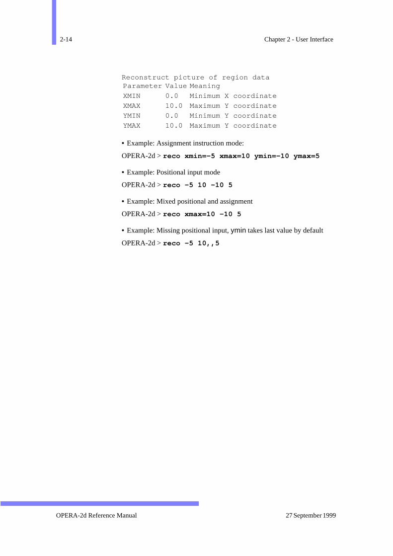
Reconstruct picture of region data
• Example: Assignment instruction mode:
OPERA-2d > reco xmin=-5 xmax=10 ymin=-10 ymax=5
• Example: Positional input mode
OPERA-2d > reco -5 10 -10 5
• Example: Mixed positional and assignment
OPERA-2d > reco xmax=10 -10 5
• Example: Missing positional input, ymin takes last value by default
OPERA-2d > reco -5 10,,5
Parameter Value Meaning
XMIN 0.0 Minimum X coordinate
XMAX 10.0 Maximum Y coordinate
YMIN 0.0 Minimum Y coordinate
YMAX 10.0 Maximum Y coordinate
OPERA-2d Reference Manual 27 September 1999
Parameter Values 2-15
ralon are has
size,ting
braic dataionse the
tored.
h also
utputd and cann in
Parameter Values
There are 4 types of value which may be assigned to a parameter: Numeric,Expression, Character and Boolean. Some parameters can take sevevalue types but some combinations, such as character and expressinot allowed. Error messages indicate if an inappropriate value typebeen used, e.g.
DCOD Message 19: Parameter ’TYPE’ cannot takenumeric values (DECODE)
Numeric Parameter Values
Numeric values are used in many commands for specifying position, number of objects etc. Numeric values can be integer, fixed or floapoint real numbers.
• Examples:
231.23E5-5.789E+04-0.04
Expressions in Parameter Values
Most parameters which can take numeric values can also take algeexpressions to specify the values. Expressions used in this way forinput are a replacement for a calculator. Variables within such expresscan be other parameters, system variables or user variables (se$ PARAmeter and $ CONStant commands on page 2-25.) These inputexpressions are not remembered; they are evaluated and the result is s
Parameters which cannot take expressions as values are those whictake character values. The text functions, %int() and %real() (page 2-17)provide a way of getting around this restriction.
Expressions are also used to specify user defined parameters for ofield quantities in post-processing. These expressions are remembereused for evaluation when referenced. Variables in output expressionsalso include the position and the field components. Full details are givechapter 3.
Version 7.1 OPERA-2d Reference Manual

2-16 Chapter 2 - User Interface
d. If aed in
s.
n the
acter,t a listmum
casesame type case-case
ithinlese
Within expressions, variable (parameter) names cannot be abbreviatecommand parameter is used in an expression, its name must be typfull.
The following characters can be used in expressions, with their usualFOR-
TRAN meanings: + – / * ( ) . No spaces can be included within expression
The following functions are supported, again using their usual FORTRAN def-initions: ABS, ACOS, ASIN, ATAN, ATAN2, COS, COSH, COTAN, EXP, LOG,
LOG10, MOD, SIN, SINH, SQRT and TAN.
N.B. Functions with 2 arguments, ATAN2 and MOD, use ‘; ’ to separate thearguments, since ‘, ’ is the separator between parameter assignments.
• Example: Parameter assignments:
OPERA-2d > line x1=x1+10 x2=x2+10
• Example: order is important since the expressions are decoded iorder given; the following commands are not equivalent:
OPERA-2d > line x1=y1+4 y1=y1+3 OPERA-2d > line y1=y1+3 x1=y1+4
• Example: Output components in post-processing:
OPERA-2d > cont comp=sqrt(x**2+y**2)*bx
Character Values for Parameters
Character values are character strings, starting with an alphabetic charusually up to 4 characters. In most cases the value is compared againsof valid options. In such cases the value can be abbreviated to its mininon-ambiguous length. Specifying the help character, ‘! ’, will cause theprogram to give a list of the valid options.
In other cases character values are used to give file names. In suchlonger strings are permitted. For operating systems which allow file nextensions or file types, the types are added automatically, the precisebeing determined from the context. On systems where file names aresensitive, file names which are entirely upper-case are given upperextensions; other file names are given lower-case extensions.
File names given as tree-names can include environment variables wthe directory part of the name (UNIX and Windows only). Variab$VFDIR (UNIX) and %VFDIR% (Windows) are defined by the softwaras the parent directory or folder holding the software.
OPERA-2d Reference Manual 27 September 1999
Parameter Values 2-17
theseaxed.ed ingshen
har-
r by
aram-er innnot
the
Some character strings are used for titles or text messages. For strings, the rule about the first character being alphabetic can be relHowever any string which contains spaces or commas must be enclosquotation marks (’ ). Quotation marks embedded within character strinmust be paired. The GUI automatically supplies quotation marks wnecessary.
Superscripts can be used in title strings. This is done by including the cacters ~E before and ~A after the superscripts. It is not necessary to use~Aif the string ends with superscripts.
• Examples:
OPERA-2d > read file=quadrupoleOPERA-2d > cont style=zoneOPERA-2d > title string=’Field after 10~E-3~As’
The last example would give the title:
Field after 10-3s
Boolean Parameter Values
Boolean parameters take the values YES or NO and are in general used foswitching features on or off. Boolean values can also be specified+PARAMETER or -PARAMETER, being equivalent to PARAMETER=YESand PARAMETER=NO.
Some parameters can take boolean or character values
• Examples:
OPERA-2d > reco +labelOPERA-2d > cont auto=yesOPERA-2d > line aver=no
Text functions
It is sometimes necessary to insert the value of an expression into a peter value as a character string, for example, to include an index numba file name or to supply a value by expression to a parameter which catake expressions. This can be done using two text functions:
%INT(expression)%REAL(expression)
These functions evaluate the expressions given and replace %func-tion(expression) on the command line with characters representing
Version 7.1 OPERA-2d Reference Manual
2-18 Chapter 2 - User Interface
om-
value (%REAL) or the nearest integer to the value (%INT).
For example, to specify a region number using a user variable:
inta reg1=%int(#ireg), reg2=%int(#ireg)
Similarly, the text function
%expr(variable)
replaces itself with the expression which variable represents. The variablecan be the parameter of a command, e.g. COMP or a user variable. It canbe used to modify the expression. In the following example, the first cponent expression is modified by dividing by a constant:
cont comp=bmod/hmodcont comp=%expr(comp)/mu0
This second command is equivalent to
cont comp=bmod/hmod/mu0
OPERA-2d Reference Manual 27 September 1999
Command Interpreter Errors 2-19
f aill ben notrectholeeter.
ich see
Command Interpreter Errors
The command interpreter provides input error recovery facilities. Iparameter name is mistyped, the other assignments on the input line wperformed, unless they are positional assignments whose position cabe determined, but command action will not continue. The incorparameter(s) can then be re-specified without having to retype the winput line. The same applies to errors detected in the value of a paramThe command interpreter will display any portion of the input string whit cannot recognize or which it thinks is in error so that the user canwhich parameters need to be re-specified.
Version 7.1 OPERA-2d Reference Manual
2-20 Chapter 2 - User Interface
mente aree the
names the
ode.
yedd by
its forhe
t that
Confidence Level
Experienced users rely on the last used defaults and the mixed assignand positional input modes to make efficient use of the programs. Therother useful features in the interpreter which can be used to reducamount which has to be typed.
Repeated commands
If the same command is being repeated many times the command need not be supplied, providing that an assignment instruction startinput line.
• Examples:
OPERA-2d > reco ymax=100OPERA-2d > ymax=10
Prompted input of parameter values
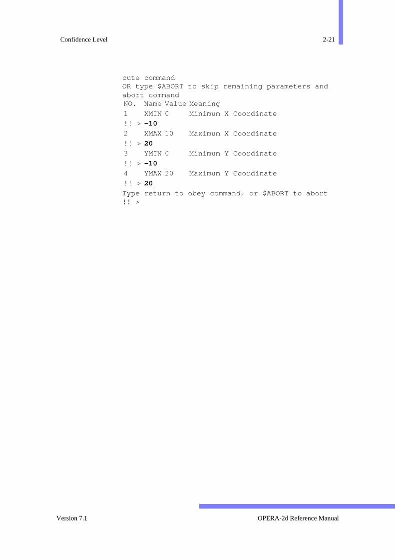
The final feature of the command processor is its prompted input mIssuing a command followed by two help escape characters (!! ) puts thecommand interpreter into prompt mode. Each parameter is displatogether with its default value and description. The default is acceptepressing the <Enter> , <Return> or ↵ key, or a new value may beentered. When all the parameters have been offered the program waeither <Enter> , <Return> or ↵ to be pressed, which then executes tcommand, or if ‘$ABORT’ is entered the command is aborted. ‘$ABORT’can be used instead of any parameter value to abort the prompting apoint and not execute the command. ‘$SKIP ’ can be used to skip over theremaining parameters and execute the command.
Note that Boolean parameters cannot be specified using +PARAMETER or-PARAMETER when in prompt mode. The character values YES and NOshould be used instead.
• Example:
OPERA-2d > reco !!There are 24 parameters For each parameter:hit return to accept default OR enter new value OR type $HELP for help OR type $SKIP to skip remaining parameters and exe-
OPERA-2d Reference Manual 27 September 1999
Confidence Level 2-21
cute command OR type $ABORT to skip remaining parameters and abort command
Type return to obey command, or $ABORT to abort!! >
NO. Name Value Meaning
1 XMIN 0 Minimum X Coordinate
!! > -10
2 XMAX10 Maximum X Coordinate
!! > 20
3 YMIN 0 Minimum Y Coordinate
!! > -10
4 YMAX20 Maximum Y Coordinate
!! > 20
Version 7.1 OPERA-2d Reference Manual
2-22 Chapter 2 - User Interface
inputs. Inrovide
f inputls asines
ven a
Prompted free format Input
Once a specific option has been selected by command or graphical the programs may prompt for extra input to define further parametersuch cases the user is shown the parameters required and asked to pvalues. The parameters are input in free format using <space> or commaas the parameter separator. The order of the parameters in this type ois shown by the prompt, however parameters defined in the manuaoptional keywords may be specified in any order. Free format input lcannot be continued on subsequent lines by means of a comma.
So that expressions can be used in free format input, each item is giname according to its position on the line. #1 is the first; #2 the second etc.
OPERA-2d Reference Manual 27 September 1999
Built-in Commands 2-23
s), sys-
d the
aturalovidere
on-
e fol-vels. the
nding
chby aand
ters,ys
Built-in Commands
‘Built-in’ commands provide control-structures (loops and conditionuser variables, command input from files and access to the operatingtem. ‘Built-in’ commands can be used at (almost) any prompt.
$ at the start of an input line introduces a ‘built-in’ command or $-com-mand. There is a built-in dictionary of commands and parameters annormal
$ command parameter=value ...
syntax can be used. The parameters have been ordered so that it is nto use positional assignments. The parameter names are useful to pron-line documentation using the ! character. Except where noted, there ano default values. $-commands must be specified in full and cannot be ctinued on subsequent lines.
Limitations
The code which implements these loops and control-structures has thlowing limitations. Control structures can be nested to a depth of 20 leThe maximum number of commands from the first control command tolast $ END (inclusive) is 10000.
Loops
Three types of loop are available: $ DO, $ FOR and $ WHILE. In eachcase the commands between the loop command and the correspo$ END command are executed a number of times.
$ DO-loops The $ DO-loop is similar to the FORTRAN do-loop. At the start of eaexecution of the loop, and index-variable is set to a value specified starting value, a final value and an increment. The syntax of the commis
prompt > $ DO index start final increment... commands to be executed ... prompt > $ END DO
The index should be the name of a user-variable, (up to 5 characbeginning with #). Its value can be changed within the loop, but is alwaset to the correct value (c.f. $ CONStant, see page 2-25) at the start of the
Version 7.1 OPERA-2d Reference Manual
2-24 Chapter 2 - User Interface
orh the
e set
sion
-
) is
and-
e
loop.
start , final and increment can be specified as numerical values expressions. Expressions are evaluated before the first pass througloop. If increment is omitted it has a default value of 1.
$ FOR-each loops
The $ FOR-each loop executes a set of commands with a user-variablin turn to each of the expressions given on the $ FOR command. The syn-tax is
prompt > $ FOR index ex1 ex2 ex3 ... ex9... commands to be executed ... prompt > $ END FOR
At least one, and at most 9, expressions (ex n) can be given. index isassigned in turn to each expression (c.f. $ PARAmeter, see page 2-25) atthe start of the loop.
$ WHILE-loops The $ WHILE-loop executes a set of commands while a logical expresremains true. The syntax is
prompt > $ WHILE ex1 logical_operator ex2 ... commands to be executed while logical expression is true ... prompt > $ END WHILE
The logical operators are EQ, NE, LE, LT, GE and GT.
Conditional commands
Three conditional commands are available: $ IF, $ ELIF and $ ELSE.The commands $ IF and $ ELIF should be followed by a logical expression. The $ ELSE command has no parameters.
A $ IF block (the commands executed if the logical expression is trueterminated by a $ ELIF, $ ELSE or $ END IF command.
A $ ELIF (else-if) block is terminated by a $ ELIF, $ ELSE or$ END IF command; it is only executed if the logical expression is true none of the preceding $ IF or $ ELIF blocks at the same level have executed.
A $ ELSE block is terminated by a $ END IF command; it is only exe-cuted if none of the preceding $ IF or $ ELIF blocks at the same level havexecuted.
OPERA-2d Reference Manual 27 September 1999

Built-in Commands 2-25
uted
uted
be
efines
.
efer-
nyn
The syntax is
prompt > $ IF value1 logical_operator value2 ... commands to be executed if logical expression is true ... prompt > $ ELIF value1 logical_operator value2... commands to be executed if previous blocks have not been execand logical expression is true ... prompt > $ ELSE ... commands to be executed if previous blocks have not been exec ... prompt > $ END IF
The logical operators are EQ, NE, LE, LT, GE and GT.
The $ END command
The $ END command ends the current block (DO, FOR, IF orWHILE). Although the block type is not logically necessary, it must specified to ensure that the user knows which block is being ENDed andto help him to supply the correct number of $ END commands. The syntaxis
prompt > $ END block_type
User Variable Commands
The $ CONStant, $ PARAmeter and $ STRIng commands define uservariables. Two further commands, $ ASK and $ PROMpt, request the userto supply values for user variables and are described on page 2-25.
Each of the three commands has the same two parameters. The first dthe NAME of the user variable and the second the VALUe. If the name isused again then the value for that variable is overwritten. If no VALUe isgiven, the current value for the NAMEd user variable is displayed. IfNAME=! is used then all the user variables currently defined are listed
The second parameter gives the VALUe for the user variable.
Numerical Variables
Numerical user variable names, defined with $ CONStant or$ PARAmeter, start with # and have up to 5 characters.
The VALUe can be a simple numeric value or can be an expression rencing other user variables or system variables. The $ CONStant com-mand evaluates the VALUe at the time the command is used and aexpression is lost. The $ PARAmeter command stores the expressio
Version 7.1 OPERA-2d Reference Manual
2-26 Chapter 2 - User Interface
the
timeging a ref-ow
given by the VALUe parameter so that it can be re-evaluated each timevariable is referenced.
• Example - to define degrees to radians conversion factor:
OPERA-2d > $ cons #fac pi/180 Assign a value to a user variable
OK
It is possible to write simple programs using the $ CONStant and$ PARAmeter commands. The user parameters are evaluated at thethey are defined and again whenever they are referenced. Thus chanuser variable definition implies a change in all user parameters whicherence that variable. This is shown by the following example. Note hchanging the value for #A implies a change in value for #B and #C.
• Example
OPERA-2d > $ cons #a 3Assign a value to a user variable
OK OPERA-2d > $ para #b #a**2 Assign an expression to a user variable
OKOPERA-2d > $ para #c #b-4Assign an expression to a user variable
OKOPERA-2d > $ cons n=!Assign an expression to a user variable
OKOPERA-2d > $ cons #a 2 Assign a value to a user variable
Name Value Expression or Value #FAC 0.0174533 0.0174533
Name Value Expression or Value #A 3.0 3.0
Name Value Expression or Value #B 9.0 #A**2
Name Value Expression or Value #C 5.0 #B–4
Name Value Expression or Value #A 3.0 3.0 #B 9.0 #A**2 #C 5.0 #B–4
Name Value Expression or Value #A 2.0 2.0
OPERA-2d Reference Manual 27 September 1999

Built-in Commands 2-27
t
cov-
his
OKOPERA-2d > $ cons n=!Assign a value to a user variable
OK
Menu Routes to $ PARAmeter and $ CONStant:
OPTIONS↓Parameters
OPTIONS↓Constants
The $ PARAmeter and $ CONStant commands are also available amany places in the GUI using the menu option Calculator .
Character Variables
Character variable names, defined with the $ STRIng command, have upto 4 characters, starting with a letter.
The VALUe can be any character string. The character string can be reered on (almost) any input line by use of the NAME surrounded by amper-sands (&). Any quotation marks used to define the string are lost. Tallows several strings to be concatenated.
• Example - storing a title for later use (note the use of %real to obtain acharacter representation of the value of a system variable (see page 2-17):
OPERA-2d > $ string t1 ’Septum Magnet’ Assign a string to a user variable
OK OPERA-2d > $ string t2 ’(RMS error %real(#err)%)’ Assign a string to a user variable
OK OPERA-2d > title ’&t1& &t2&’ tr Set a title for the graphics window
The title displayed is ‘Septum Magnet (RMS error 5.23146%)’.
Name Value Expression or Value #A 2.0 2.0 #B 4.0 #A**2 #C 0.0 #B–4
Name String T1 Septum Magnet
Name String T2 (RMS error 5.23146%)
Version 7.1 OPERA-2d Reference Manual

2-28 Chapter 2 - User Interface
ndten-
isluded
the
ed.tput after
foris
rent.
ional
f the
Command Input Files
The $ COMInput command allows commands to be read from a file aadditionally sets the message output mode. If a file with no file name exsion is given, the extension comi is assumed. The syntax is:
prompt > $ COMI filename mode
If the $ COMInput command appears in a loop, the file of commandsread each time the loop is executed. Almost any commands can be incin command input files.
Menu Route to $ COMInput :
FILE ↓Commands in
Text Output Modes
Some commands produce a lot of text output to the terminal. To avoidrequest to:
Type S to stop or any other character to continue.
which occurs in PAGEd mode, the parameter MODE should be set toCONTinuous.
The parameter MODE applies whether or not a command file is requestIn PAGEd mode (the default), the program counts the lines of text outo the text window and issues the above request to continue or stopeach page of continuous output. In CONTinuous mode, the text outputcontinues until the next input is requested, and with MODE=OFF most ofthe normal text output does not appear at all. MODE=PICTures is usefulfor running ‘demonstration’ command files, since the program pausesan <Enter> , <Return> or ↵ before each time the graphics window cleared, but does not stop when the text window is full. In each MODE, textoutput is written to the dialogue file.
When menus are being used the text output modes are slightly diffeMODE=PAGEd behaves the same as MODE=CONTinuous. While a com-mand file is being read with MODE=CONTinuous, text output appears onthe text window and does not appear in GUI MessageBoxes. An additoption, MODE=MESSage causes the GUI MessageBoxes to be used.
Menu Route for Text Output Mode:
FILE ↓Commands in
Execution of command files can be interrupted using the settings oMODE parameter. It can also be interrupted by inclusion of $ PAUSE
OPERA-2d Reference Manual 27 September 1999
Built-in Commands 2-29
gned
f. theo the
gram
or
a file
o 10.
to
leaseent
commands. The syntax is:
prompt > $ PAUSE seconds
$ PAUSe waits for a number of seconds before continuing. If secondsis omitted or is ≤0, the program waits for the user to type <Enter> ,<Return> or ↵ or dismiss a MessageBox before continuing.
Prompting Commands
Command input files can contain user variables, which must be assivalues before the commands are executed. The $ ASK command can beused to request the user to supply a value for a numerical variable (c.$ CONStant command). The $ PROMpt command can be used trequest the user to supply a value for a character variable (c.f.$ STRINg command). The syntax is:
prompt > $ ASK #name prompt_string prompt > $ PROMpt name prompt_string
The optional prompt_string is displayed to show what input isrequired. The value must be supplied at the keyboard before the prowill continue.
N.B. $ ASK and $ PROMpt cannot be used in OPERA-3d pre-processdata files; they can only be used in command input files.
User Input/Output Commands
There are seven commands for user input and output of files. Before can be read or written it must be opened.
prompt > $ OPEN stream filenm authority ± REDIrect
opens a file on a logical stream number which can be in the range 1 tThe file can be used in 4 ways, depending on the authority . These areREAD an old file, WRITe a new file, OVERwrite an old file and APPEndto an old file.
If +REDIrect is selected for an output file, the output which is writtenthe dialogue file will be written to the output file as well.
When all input or output has been completed a file can be closed to reits logical stream number or to make it available for opening with differauthority.
prompt > $ CLOSe stream
closes a logical stream number in the range 1 to 10.
Version 7.1 OPERA-2d Reference Manual
2-30 Chapter 2 - User Interface
ven users on
e-vi-ed
ser
style
atshrit-
aces
ning
the
r data
The $ READ command takes one line from the file opened on the gilogical stream number and assigns any numerical data on the line tovariables. Up to 20 variable names can be given. Any character stringthe line are ignored. The syntax is
prompt > $ READ stream #var1 #var2 #var3 ...
The $ WRITe command is similar to the $ READ command. The syntax is
prompt > $ WRITe stream data1 data2 ... ±OUTPut
Up to 20 data items can be supplied.
A line of output can be built up using several $ WRITe commands. If thisis necessary the first $ WRITe commands should have -OUTPut . The last$ WRITe should have +OUTPut. The data from the second and subsquent $ WRITe commands will be positioned after the data of the preous write commands in an internal buffer which is written and re-initializwhen +OUTPut is used.
Data items on a $ WRITe command can be numerical, characters or uvariables. Before the $ WRITe command is used, the $ FORMat and$ ASSIgn commands should be used to define the type of data and theof output to be used for each item on the $ WRITe command.
The $ FORMat command can be used to define up to 20 different formfor output items. In each form the width can be specified as zero whicimplies that the program should calculate a width to fit the data being wten. The syntax has one of the following forms.
• To define a format for character data, truncated or padded with spto a particular width :
prompt > $ FORMat number CHARacter width
• To define a fixed point format for numerical data, with decs as thenumber of decimal places.
prompt > $ FORMat number FIXEd width decs
• To define a floating point format for numerical data: prompt > $ FORMat number EXPOnential width
• To define a format for integer data: prompt > $ FORMat number INTEger width
• To define a format for a user variable to display the expression defithe variable truncated or padded to a particular width :
prompt > $ FORMat number USER width
• To define a character string to be output irrespective of the data on$ WRITe command (N.B. It is necessary to define STRIng formatscontaining spaces to appear between other data items if those otheitems are written with a width of zero.):
OPERA-2d Reference Manual 27 September 1999
Built-in Commands 2-31
sub-e
tax
s intput
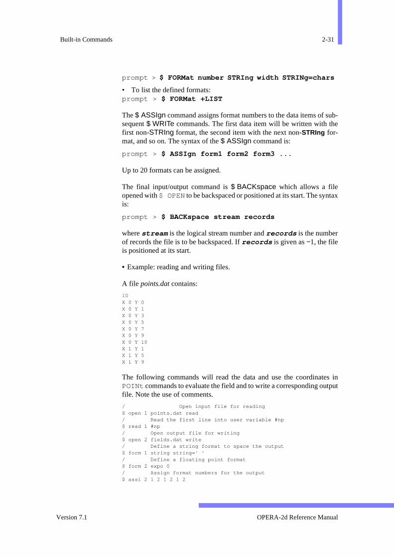
prompt > $ FORMat number STRIng width STRINg=chars
• To list the defined formats: prompt > $ FORMat +LIST
The $ ASSIgn command assigns format numbers to the data items of sequent $ WRITe commands. The first data item will be written with thfirst non-STRIng format, the second item with the next non-STRIng for-mat, and so on. The syntax of the $ ASSIgn command is:
prompt > $ ASSIgn form1 form2 form3 ...
Up to 20 formats can be assigned.
The final input/output command is $ BACKspace which allows a fileopened with $ OPEN to be backspaced or positioned at its start. The synis:
prompt > $ BACKspace stream records
where stream is the logical stream number and records is the numberof records the file is to be backspaced. If records is given as −1, the fileis positioned at its start.
• Example: reading and writing files.
A file points.dat contains:
10 X 0 Y 0 X 0 Y 1 X 0 Y 3 X 0 Y 5 X 0 Y 7 X 0 Y 9 X 0 Y 10 X 1 Y 1 X 1 Y 5 X 1 Y 9
The following commands will read the data and use the coordinatePOINt commands to evaluate the field and to write a corresponding oufile. Note the use of comments.
/ Open input file for reading $ open 1 points.dat read / Read the first line into user variable #np $ read 1 #np / Open output file for writing $ open 2 fields.dat write / Define a string format to space the output $ form 1 string string=' ' / Define a floating point format $ form 2 expo 0 / Assign format numbers for the output $ assi 2 1 2 1 2 1 2
Version 7.1 OPERA-2d Reference Manual

2-32 Chapter 2 - User Interface
e com-iles, the
to a
- withheses.:
/ Start a loop from 1 to #np $ do #i 1 #np / Read #x and #y from input file $ read 1 #x #y / Evaluate fields at #x #y poin meth=cart xp=#x yp=#y / Write coordinates and flux density to output file $ write 2 x y bx by / End of loop $ end do / Close files $ close 1 $ close 2
The output file, fields.dat contains:
0.0 0.0 1.179564E-07 -0.000120992 0.0 1.0 6.322637E-08 -0.000121184 0.0 3.0 3.739035E-06 -0.000133139 0.0 5.0 -4.42901E-06 -0.00013248 0.0 7.0 -7.59639E-06 -8.48776E-05 0.0 9.0 -7.74227E-06 -2.32268E-05 0.0 10.0 0.0 0.0 1.0 1.0 4.347521E-07 -0.000121116 1.0 5.0 -1.34893E-05 -0.000141764 1.0 9.0 -3.10067E-05 -3.09315E-05
Operating System Commands
There are two commands to execute operating system commands:
prompt > $ OS str1 str2 str3 str4 str5 str6prompt > $ CD directory
$ OS passes up to 6 strings (str n) which together form a command to thoperating system to be executed. This can be used to issue singlemands to list names of files in directories (folders), delete or rename fetc., using the normal syntax of the operating system. The output fromcommands is listed, with the usual page breaks.
The $ OS command on UNIX systems
On UNIX systems, in order to redirect the output from the command file, the program adds to the command the appropriate notation:
• in c-shell: user_command >& TeMpOsCmNdFiLe
• in other shells: user_command > TeMpOsCmNdFiLe 2>&1
The contents of the file, TeMpOsCmNdFiLe, are then listed. For this reason, shell metacharacters within the user command should be usedcare and it might be necessary to enclose the user command in parentFor example, to run a background command use the following syntax
$OS (xterm &)
OPERA-2d Reference Manual 27 September 1999

Built-in Commands 2-33
aveds
s (
rting
hile
such
n ben-
are.
The $ OS command on Windows systems
On Windows systems a limited set of Command Prompt command hbeen implemented, although without full functionality. The commanavailable are:
• dir or ls to list files in the current folder
• del or rm to delete a file
• mkdir or md to create a new folder in the current folder
• ren to rename a file
• copy to copy a file
• pwd or cd to report the current folder
N.B. File names including spaces should be enclosed in double-quote" ).
The $ OS operaanl command
On all operating systems an additional command is available for staanalysis programs from the interactive programs. The syntax is
$ OS operaanl program datafile mode
where
• program is one of AC, RM, SA, SP, ST, TH, THTR, TR or VL
• datafile is the name of the op2 file to be analysed
• mode is FORE or BACK. The interactive program waits while FORE-ground analysis jobs are run, but can be continued or ended wBACKground jobs are run.
The $ CD command
Because the $ OS command spawns a new sub-process, a command as
prompt > $ OS cd directory
has no lasting effect. The $ CD directory command should be usedinstead to change the currect directory or folder. Directory names cagiven using environment variables (UNIX and Windows only). Enviroment variables $VFDIR (on UNIX systems) and %VFDIR% (on Windowssystems) are defined by the software as the parent directory of the softw
Menu Routes: FILE ↓OS command
FILE ↓Change directory
Version 7.1 OPERA-2d Reference Manual
2-34 Chapter 2 - User Interface
given
l:
com-ents
per-
Command Separator and Comments
The command separator allows several keyboard commands to be on one input line. The command separator is the vertical bar, | .
• Example: the RECOnstruct command with mesh in only one materiaOPERA > reco -mesh mate=all | -erase mate=1 +mesh
If the first non-space character on an input line is / , the line is treated as acomment. Comments are output to the dialogue file and comments in mand files are displayed as the file is being read. In menu mode, commwhich start /* are displayed in GUI MessageBoxes.
In some contexts it is not possible to give comments, since for some oating systems, file names can begin with / .
OPERA-2d Reference Manual 27 September 1999
Euler Angles 2-35
t or ae ori-:
iple
.
-s
o
n
Euler Angles
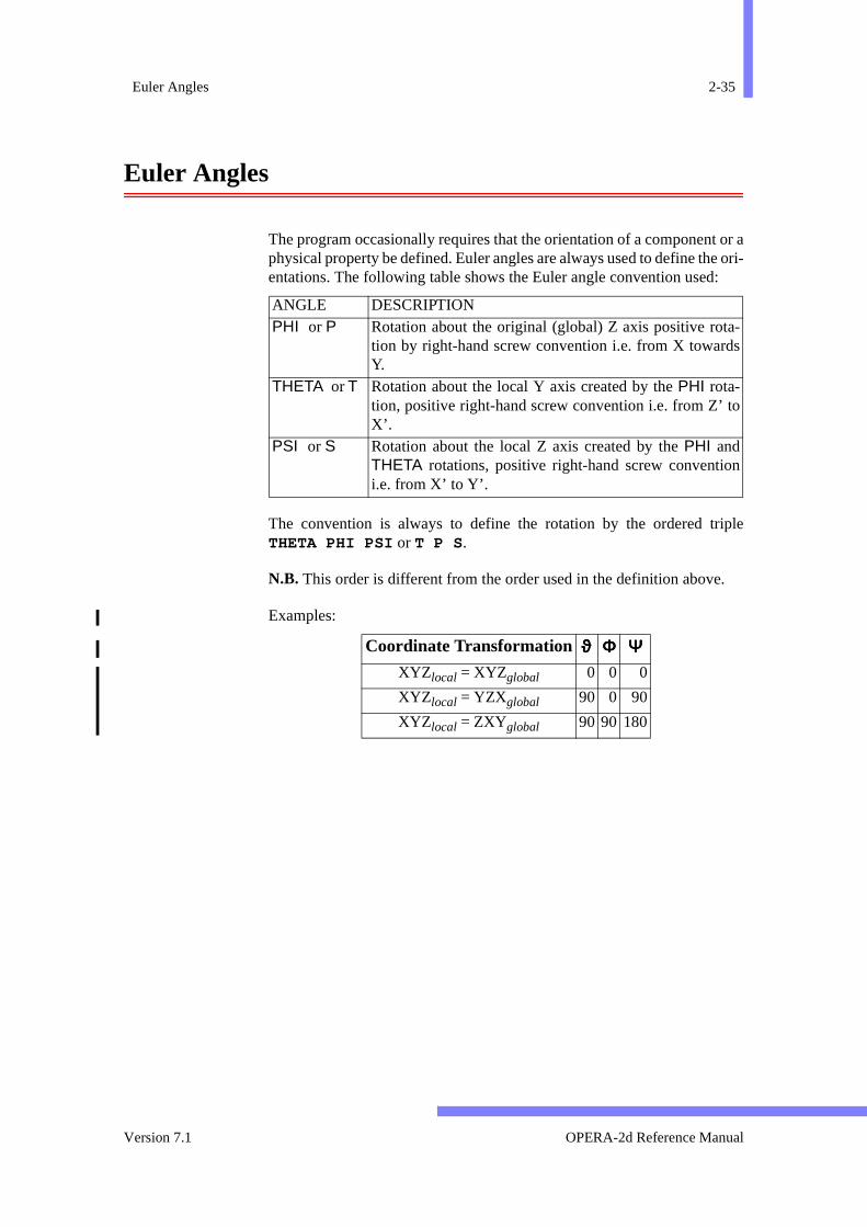
The program occasionally requires that the orientation of a componenphysical property be defined. Euler angles are always used to define thentations. The following table shows the Euler angle convention used
The convention is always to define the rotation by the ordered trTHETA PHI PSI or T P S .
N.B. This order is different from the order used in the definition above
Examples:
ANGLE DESCRIPTION PHI or P Rotation about the original (global) Z axis positive rota
tion by right-hand screw convention i.e. from X towardY.
THETA or T Rotation about the local Y axis created by the PHI rota-tion, positive right-hand screw convention i.e. from Z’ tX’.
PSI or S Rotation about the local Z axis created by the PHI andTHETA rotations, positive right-hand screw conventioi.e. from X’ to Y’.
Coordinate Transformation ϑϑϑϑ ΦΦΦΦ ΨΨΨΨXYZ local = XYZglobal 0 0 0
XYZ local = YZXglobal 90 0 90
XYZ local = ZXYglobal 90 90 180
Version 7.1 OPERA-2d Reference Manual

2-36 Chapter 2 - User Interface
OPERA-2d Reference Manual 27 September 1999
Chapter 3The Pre and Post-Processor
pre-lysis
sionalag-esh
s.
pres- ther twoions.
atingtells withet
key-pter 2,uide.-Proc- on
Introduction
The OPERA-2d pre and post-processor is an interactive program forparing the data and processing the results from the OPERA-2d anaprograms.
The pre-processing commands are used to create and edit two dimenfinite element models, define material characteristics for non-linear mnetic or dielectric components, display pictures of the models and the mand output data files in the formats accepted by the analysis program
The post-processing commands allow many field components, or exsions of field components to be viewed at points, along lines or overcross-section of the model. Components can be integrated in one odimensions and particle trajectories can be calculated in three dimens
When the Pre and Post-Processor starts, on UNIX and OpenVMS opersystems, the first input the user must give is ‘device nomination’. This the program what graphics options should be used. This is describedthe DEVIce command (page 3-39) which can be used at any time to resthe device, or change graphics options.
As the Pre and Post-Processor starts or when it is restarted with the CLEArcommand (page 3-28), the program looks for a file called opera2.comi, andif it exists, executes the commands it contains. (See “Command InputFiles” on page 2-28.)
The Graphical User Interface (GUI) and the style and syntax of the board commands of the Pre and Post-Processor are described in Chaand the particular requirements of the analysis programs in the User GThe rest of this chapter describes the commands of the Pre and Postessor. The “The Pre and Post-Processor Quick Reference Guide”
OPERA-2d Reference Manual Version 7.1

3-2 Chapter 3 - The Pre and Post-Processor
n’ they
ed in them
page 3-3 lists the top-level menu items and the first level ‘pull-dowmenus, and each of the keyboard commands in the order in whichappear in the program. “Using Expressions” on page 3-10 explains the useof expressions and system variables. Then each command is explaindetail with references to the menu options which can be used to access(from page 3-19 to page 3-183).
The “Graphical User Interface Reference” on page 3-185 lists all the menuitems with references to the corresponding commands.
OPERA-2d Reference Manual 27 September 1999
The Pre and Post-Processor Quick Reference Guide 3-3
essor.
This sec-sted
the
The Pre and Post-Processor Quick Reference Guide
The GUI Menus
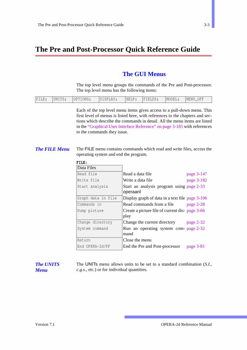
The top level menu groups the commands of the Pre and Post-procThe top level menu has the following items:
Each of the top level menu items gives access to a pull-down menu.first level of menus is listed here, with references to the chapters andtions which describe the commands in detail. All the menu items are liin the “Graphical User Interface Reference” on page 3-185 with referencesto the commands they issue.
The FILE Menu The FILE menu contains commands which read and write files, accessoperating system and end the program.
FILE ↓
The UNITS Menu
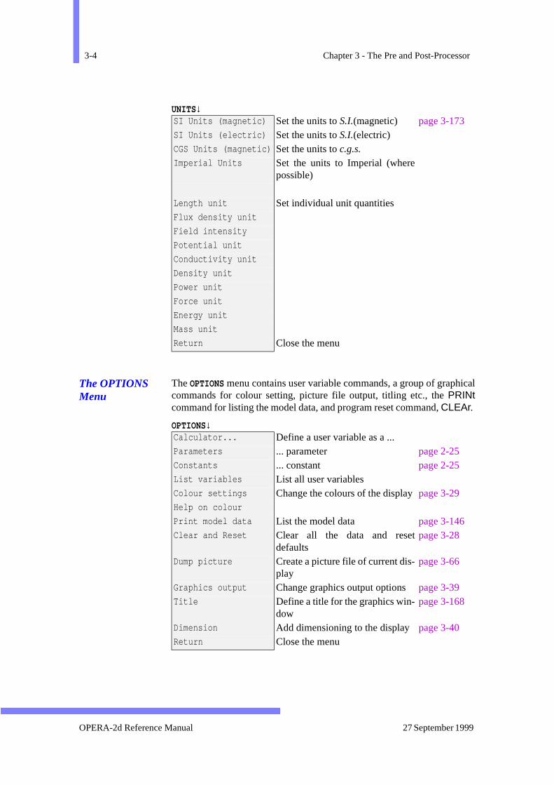
The UNITs menu allows units to be set to a standard combination (S.I.,c.g.s., etc.) or for individual quantities.
FILE ↓ UNITS↓ OPTIONS↓ DISPLAY↓ HELP↓ FIELDS↓ MODEL↓ MENU_OFF
Data FilesRead file Read a data file page 3-147Write file Write a data file page 3-182Start analysis Start an analysis program using
operaanl page 2-33
Graph data in file Display graph of data in a text filepage 3-106Commands in Read commands from a file page 2-28Dump picture Create a picture file of current dis-
playpage 3-66
Change directory Change the current directory page 2-32System command Run an operating system com-
mand page 2-32
Return Close the menu End OPERA-2d/PP End the Pre and Post-processor page 3-81
Version 7.1 OPERA-2d Reference Manual
3-4 Chapter 3 - The Pre and Post-Processor
ical
UNITS↓
The OPTIONS Menu
The OPTIONS menu contains user variable commands, a group of graphcommands for colour setting, picture file output, titling etc., the PRINtcommand for listing the model data, and program reset command, CLEAr.
OPTIONS↓
SI Units (magnetic) Set the units to S.I.(magnetic) page 3-173SI Units (electric) Set the units to S.I.(electric)CGS Units (magnetic) Set the units to c.g.s.Imperial Units Set the units to Imperial (where
possible)
Length unit Set individual unit quantitiesFlux density unit
Field intensity
Potential unit
Conductivity unit
Density unit
Power unit
Force unit
Energy unit
Mass unit
Return Close the menu
Calculator... Define a user variable as a ... Parameters ... parameter page 2-25Constants ... constant page 2-25List variables List all user variables Colour settings Change the colours of the display page 3-29Help on colour
Print model data List the model data page 3-146Clear and Reset Clear all the data and reset
defaults page 3-28
Dump picture Create a picture file of current dis-play
page 3-66
Graphics output Change graphics output options page 3-39Title Define a title for the graphics win-
dow page 3-168
Dimension Add dimensioning to the display page 3-40Return Close the menu
OPERA-2d Reference Manual 27 September 1999

The Pre and Post-Processor Quick Reference Guide 3-5
itsalso
and to the
The DISPLAY Menu
The DISPLAY menu re-displays the picture. It allows the coordinate limto be changed graphically by pan or zoom functions or numerically. It controls the style and contents of the display.
DISPLAY↓
The HELP Menu The HELP menu gives information on how to use the program, the GUI the keyboard commands. The chapter and section numbers here referlocation of additional information on the same topics.
HELP↓
Refresh Re-display the data page 3-149Zoom in/out Re-display, changing the size page 3-183Pan Re-display, changing the position page 3-140
For the next display ... Axes limits ... set the size page 3-149Display all ... select all regions page 3-149Region numbers ... select region numbers page 3-149Material numbers ... select material numbers page 3-149Region group ... select region group page 3-149Post-processing ... set style options for Post-
processing page 3-149
Style ... choose the style page 3-149Axes ... select the axes page 3-149Nodes ... select nodes page 3-149+Labels ... switch display of labels page 3-149+Mesh ... switch display of elements page 3-149+C_line ... switch display of construction
lines page 3-149
+Back ... switch display of backgroundregion
page 3-149
Return Close the menu
System Overview Overview of OPERA-2d chapter 1The GUI How to use the GUI page 2-2Command line How to use the command line page 2-9Model input How to define a model Boundary values How to define boundary condi-
tions page 3-134
Field calculations How to obtain field values System Variables How to use system variables page 3-10Return Close the menu
Version 7.1 OPERA-2d Reference Manual
3-6 Chapter 3 - The Pre and Post-Processor
Post-
s.
The FIELDS Menu
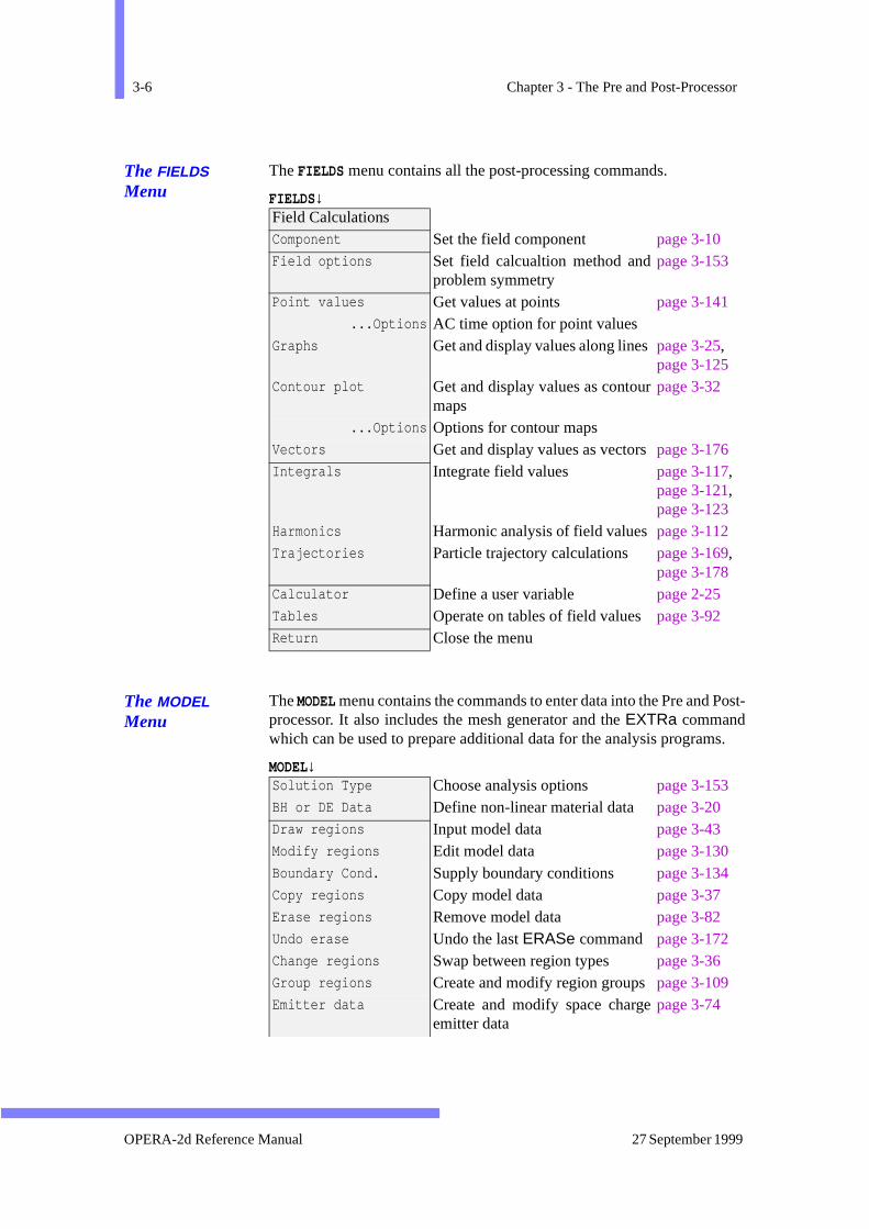
The FIELDS menu contains all the post-processing commands.
FIELDS↓
The MODEL Menu
The MODEL menu contains the commands to enter data into the Pre and processor. It also includes the mesh generator and the EXTRa commandwhich can be used to prepare additional data for the analysis program
MODEL↓
Field CalculationsComponent Set the field component page 3-10Field options Set field calcualtion method and
problem symmetrypage 3-153
Point values Get values at points page 3-141...Options AC time option for point values
Graphs Get and display values along lines page 3-25,page 3-125
Contour plot Get and display values as contourmaps
page 3-32
...Options Options for contour maps Vectors Get and display values as vectors page 3-176Integrals Integrate field values page 3-117,
page 3-121,page 3-123
Harmonics Harmonic analysis of field values page 3-112Trajectories Particle trajectory calculations page 3-169,
page 3-178Calculator Define a user variable page 2-25Tables Operate on tables of field valuespage 3-92Return Close the menu
Solution Type Choose analysis options page 3-153BH or DE Data Define non-linear material data page 3-20Draw regions Input model data page 3-43Modify regions Edit model data page 3-130Boundary Cond. Supply boundary conditions page 3-134Copy regions Copy model data page 3-37Erase regions Remove model data page 3-82Undo erase Undo the last ERASe command page 3-172Change regions Swap between region types page 3-36Group regions Create and modify region groups page 3-109Emitter data Create and modify space charge
emitter data page 3-74
OPERA-2d Reference Manual 27 September 1999
The Pre and Post-Processor Quick Reference Guide 3-7
he
ds
and
d
.
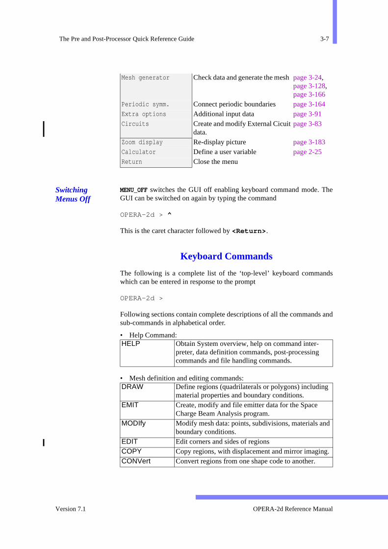
Switching Menus Off
MENU_OFF switches the GUI off enabling keyboard command mode. TGUI can be switched on again by typing the command
OPERA-2d > ^
This is the caret character followed by <Return> .
Keyboard Commands
The following is a complete list of the ‘top-level’ keyboard commanwhich can be entered in response to the prompt
OPERA-2d >
Following sections contain complete descriptions of all the commandssub-commands in alphabetical order.
• Help Command:
• Mesh definition and editing commands:
Mesh generator Check data and generate the mesh page 3-24,page 3-128,page 3-166
Periodic symm. Connect periodic boundaries page 3-164Extra options Additional input data page 3-91Circuits Create and modify External Cicuit
data. page 3-83
Zoom display Re-display picture page 3-183Calculator Define a user variable page 2-25Return Close the menu
HELP Obtain System overview, help on command inter-preter, data definition commands, post-processing commands and file handling commands.
DRAW Define regions (quadrilaterals or polygons) includingmaterial properties and boundary conditions.
EMIT Create, modify and file emitter data for the Space Charge Beam Analysis program.
MODIfy Modify mesh data: points, subdivisions, materials anboundary conditions.
EDIT Edit corners and sides of regionsCOPY Copy regions, with displacement and mirror imagingCONVert Convert regions from one shape code to another.
Version 7.1 OPERA-2d Reference Manual

3-8 Chapter 3 - The Pre and Post-Processor
ts
m,
ints
on
ir-
as
is-
• Picture display commands:
• Data grouping and printing commands:
• Material B-H characteristic, definition and editing command:
• Analysis option setting command:
• Mesh generating and data checking commands:
• Command to impose extra analysis conditions:
• External Circuit command:
• Post-processing commands:
ERASe Erase regions.SYMMetry Connect region faces which have periodicity condi-
tions. UNDO Return model to the state before the last ERASe or
MODIfy.
RECOnstruct Display pictures of the geometry, choosing which parare shown and how.
ZOOM Change size of picture by zooming in or out.PAN Change position of picture within the graphics win-
dow.
PRINt Print all or some of the region data. GROUp Create and modify groups of region numbers.
BHDAta Enter the BH data definition and editing mode.
SET Set analysis options: element type, coordinate systepotential type, field type etc.
SOLVe Set analysis program specific data.
CHECk Check data thoroughly. TEST Test each region against its neighbours and add po
if necessary to match faces to prepare for meshing. MESH Generate all finite element mesh data.
EXTRa Sub-command mode to impose extra conditions analysis and define stress analysis data.
EXTErnal Sub-command mode to define and modify external ccuit data.
POINt Evaluate field components at a point. LINE Evaluate field components along a line and display
a graph. CIRCle Evaluate field components along a circular arc and d
play as a graph.
OPERA-2d Reference Manual 27 September 1999
The Pre and Post-Processor Quick Reference Guide 3-9
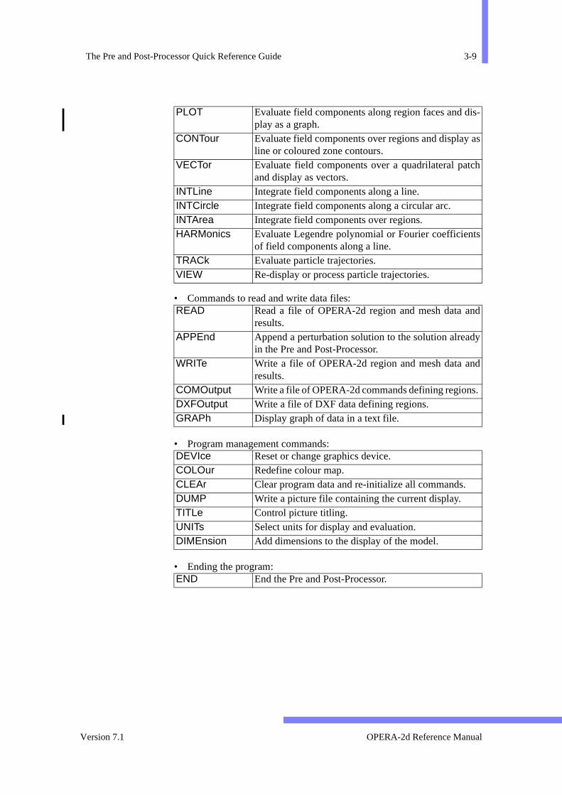
is-
as
ch
ts
nd
y
d
.
• Commands to read and write data files:
• Program management commands:
• Ending the program:
PLOT Evaluate field components along region faces and dplay as a graph.
CONTour Evaluate field components over regions and displayline or coloured zone contours.
VECTor Evaluate field components over a quadrilateral patand display as vectors.
INTLine Integrate field components along a line. INTCircle Integrate field components along a circular arc. INTArea Integrate field components over regions. HARMonics Evaluate Legendre polynomial or Fourier coefficien
of field components along a line. TRACk Evaluate particle trajectories. VIEW Re-display or process particle trajectories.
READ Read a file of OPERA-2d region and mesh data aresults.
APPEnd Append a perturbation solution to the solution alreadin the Pre and Post-Processor.
WRITe Write a file of OPERA-2d region and mesh data anresults.
COMOutput Write a file of OPERA-2d commands defining regionsDXFOutput Write a file of DXF data defining regions. GRAPh Display graph of data in a text file.
DEVIce Reset or change graphics device. COLOur Redefine colour map. CLEAr Clear program data and re-initialize all commands. DUMP Write a picture file containing the current display. TITLe Control picture titling. UNITs Select units for display and evaluation. DIMEnsion Add dimensions to the display of the model.
END End the Pre and Post-Processor.
Version 7.1 OPERA-2d Reference Manual

3-10 Chapter 3 - The Pre and Post-Processor
cribedichid pre-
char-eters,ut andricalntterrent
or
fter
res-bles
meters
ame-
m
others
Using Expressions
The command decoder used with the Pre and Post-Processor is desfully in chapter 2. More details are given here concerning the way in whthe Pre and Post-Processor makes use of the expression analyser to aprocessing and evaluate output field components.
Any parameter which takes a numerical value (but cannot also take a acter value) can be assigned to an expression in terms of other paramsystem and user variables. These are, in most cases, evaluated on inpthe resulting value is stored. The exceptions to this are the numeparameters of the MODIfy command and the output field componeparameters. In the MODIfy command, any expression given as a paramevalue will be evaluated for each region in turn. Thus to double the curdensity in the whole problem, the following command could be given:
• Example OPERA-2d > modi reg1=1 * dens=dens*2
The system variables AREA and (in axisymmetry) VOLUME are set foreach region within MODIfy so that material properties such as currentcharge density can be set in terms of total values. (N.B. AREA and VOL-UME are calculated for each region during display of that region. AREADing a data file, values for AREA and VOLUME will be invalid untilthe RECOnstruct command has been used.)
Most post-processing commands have parameters COMPonent or VX andVY, to define scalar and vector field components to be displayed. Expsions can be used to define these output field quantities with the variabeing System Variables, user constants, user parameters and the paraof the commands. The expressions are evaluated for each field point.
The expressions for COMPonent, VX and VY used with any commandbecome the default value for all other commands which use those parters. The initial value for COMPonent is POT and VX and VY are initiallyset to BX and BY.
The $ CONStant and $ PARAmeter commands can be used to perforfurther calculations on the results of the commands (seepage 2-25).
System Variables
There are 7 sets of system variables: some are always available but are set depending on the coordinate system (XY or AXI) and the field type(MAGNetic or ELECtric) (see SET command, page 3-153). The final set
OPERA-2d Reference Manual 27 September 1999
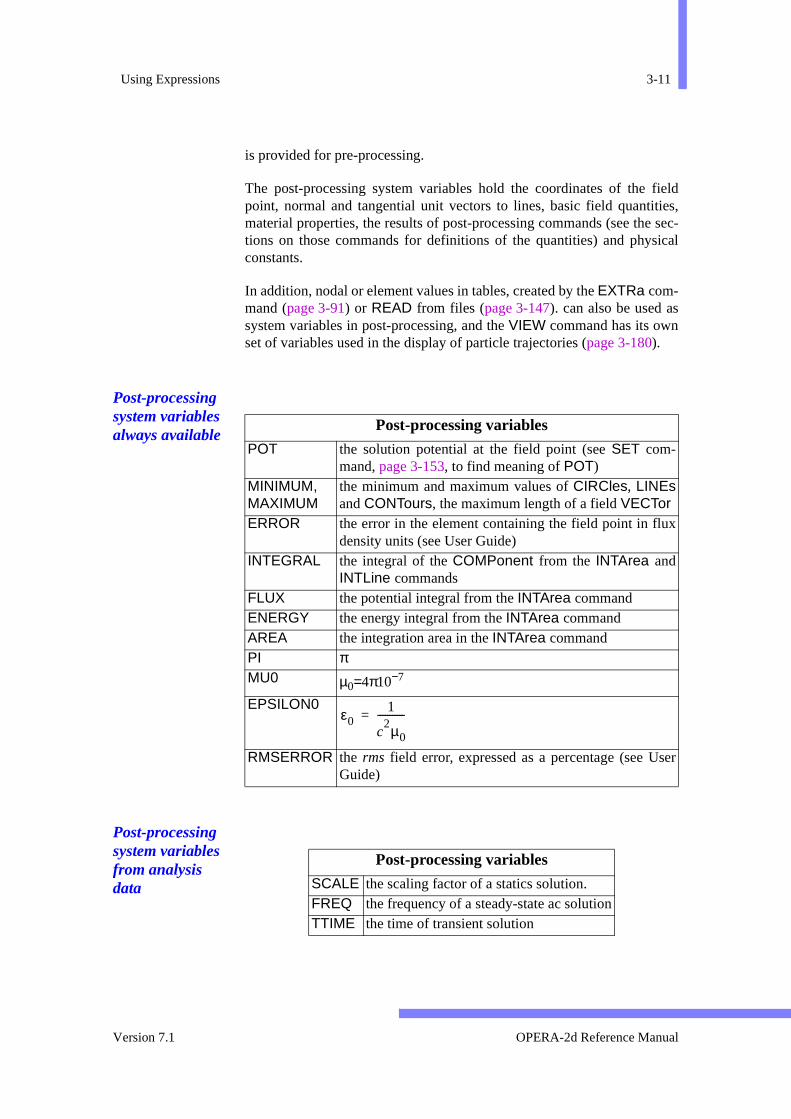
Using Expressions 3-11
fieldies,e sec-ical
s
x
ser
is provided for pre-processing.
The post-processing system variables hold the coordinates of the point, normal and tangential unit vectors to lines, basic field quantitmaterial properties, the results of post-processing commands (see thtions on those commands for definitions of the quantities) and physconstants.
In addition, nodal or element values in tables, created by the EXTRa com-mand (page 3-91) or READ from files (page 3-147). can also be used asystem variables in post-processing, and the VIEW command has its ownset of variables used in the display of particle trajectories (page 3-180).
Post-processing system variables always available
Post-processing system variables from analysis data
Post-processing variables
POT the solution potential at the field point (see SET com-mand, page 3-153, to find meaning of POT)
MINIMUM,MAXIMUM
the minimum and maximum values of CIRCles, LINEsand CONTours, the maximum length of a field VECTor
ERROR the error in the element containing the field point in fludensity units (see User Guide)
INTEGRAL the integral of the COMPonent from the INTArea andINTLine commands
FLUX the potential integral from the INTArea commandENERGY the energy integral from the INTArea commandAREA the integration area in the INTArea commandPI πMU0 µ0=4π10−7
EPSILON0
RMSERROR the rms field error, expressed as a percentage (see UGuide)
ε01
c2µ0
-----------=
Post-processing variables
SCALE the scaling factor of a statics solution.FREQ the frequency of a steady-state ac solutionTTIME the time of transient solution
Version 7.1 OPERA-2d Reference Manual

3-12 Chapter 3 - The Pre and Post-Processor
ld
ld
ld
ld
ur-ent
System variables for magnetics in xy
XY Magnetics
X, Y the coordinates of the field pointTVX, TVY the tangential unit vector to a lineNVX, NVY the normal unit vector to a lineDADT the time derivative of vector potentialHX, HY,HMOD
the field strength at the field point
HCX, HCY the coercive force at the field pointBX, BY,BMOD
the flux density at the field point
MU the relative permeability at the field pointHXDX
the field gradient ( ) in the element containing the fie
pointHXDY
the field gradient ( ) in the element containing the fie
pointHYDX
the field gradient ( ) in the element containing the fie
pointHYDY
the field gradient ( ) in the element containing the fie
pointJ the current density at the field pointLX, LY the Lorentz force density ( ) at the field point
SIGMA the conductivity in the element containing the field pointPHASE the permanent magnet or lamination direction or drive c
rent phase angle or permeability phase angle in the elemcontaining the field point
VELOCITY the velocity of the element containing the field pointHDB
the stored energy integral at the field point
FX, FY the force integral from the INTArea, INTCircle and INTLinecommands
TORQUE the torque integral in the INTCircle and INTLine commandsCURRENT the total current integral from the INTArea commandPOWER the power loss integral from the INTArea command
x∂∂Hx
y∂∂Hx
x∂∂Hy
y∂∂Hy
J B×
H ∂B⋅( )∫
OPERA-2d Reference Manual 27 September 1999
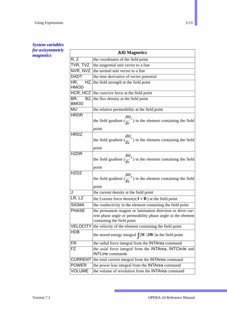
Using Expressions 3-13
ld
ld
ld
ld
ur-ent
System variables for axisymmetric magnetics
AXI Magnetics
R, Z the coordinates of the field pointTVR, TVZ the tangential unit vector to a lineNVR, NVZ the normal unit vector to a lineDADT the time derivative of vector potentialHR, HZ,HMOD
the field strength at the field point
HCR, HCZ the coercive force at the field pointBR, BZ,BMOD
the flux density at the field point
MU the relative permeability at the field pointHRDR
the field gradient ( ) in the element containing the fie
pointHRDZ
the field gradient ( ) in the element containing the fie
pointHZDR
the field gradient ( ) in the element containing the fie
pointHZDZ
the field gradient ( ) in the element containing the fie
pointJ the current density at the field pointLR, LZ the Lorentz force density( ) at the field point
SIGMA the conductivity in the element containing the field pointPHASE the permanent magnet or lamination direction or drive c
rent phase angle or permeability phase angle in the elemcontaining the field point
VELOCITY the velocity of the element containing the field pointHDB
the stored energy integral at the field point
FR the radial force integral from the INTArea commandFZ the axial force integral from the INTArea, INTCircle and
INTLine commandsCURRENT the total current integral from the INTArea commandPOWER the power loss integral from the INTArea commandVOLUME the volume of revolution from the INTArea command
r∂∂Hr
z∂∂Hr
r∂∂Hz
z∂∂Hz
J B×
H ∂B⋅( )∫
Version 7.1 OPERA-2d Reference Manual

3-14 Chapter 3 - The Pre and Post-Processor
ld
ld
ld
ld
System variables for electrostatics in xy
System variables for axisymmetric electrostatics
XY Electrostatics
X, Y the coordinates of the field pointTVX, TVY the tangential unit vector to a lineNVX, NVY the normal unit vector to a lineEX, EY,EMOD
the field strength at the field point
DVX, DVY,DMOD
the electric displacement at the field point
CHARDEN the charge density at the field pointEPSILON the relative permittivityEXDX
the field gradient ( ) in the element containing the fie
pointEXDY
the field gradient ( ) in the element containing the fie
pointEYDX
the field gradient ( ) in the element containing the fie
pointEYDY
the field gradient ( ) in the element containing the fie
pointEDD
the stored energy integral at the field point
FX, FY the force integral from the INTCircle and INTLine commandTORQUE the torque integral from the INTCircle and INTLine com-
mandCHARGE the total charge integral from the INTArea command
x∂∂Ex
y∂∂Ex
x∂∂Ey
y∂∂Ey
E ∂D⋅( )∫
AXI Electrostatics
R, Z the coordinates of the field pointTVR, TVZ the tangential unit vector to a lineNVR, NVZ the normal unit vector to a lineER, EZ,EMOD
the field strength at the field point
OPERA-2d Reference Manual 27 September 1999
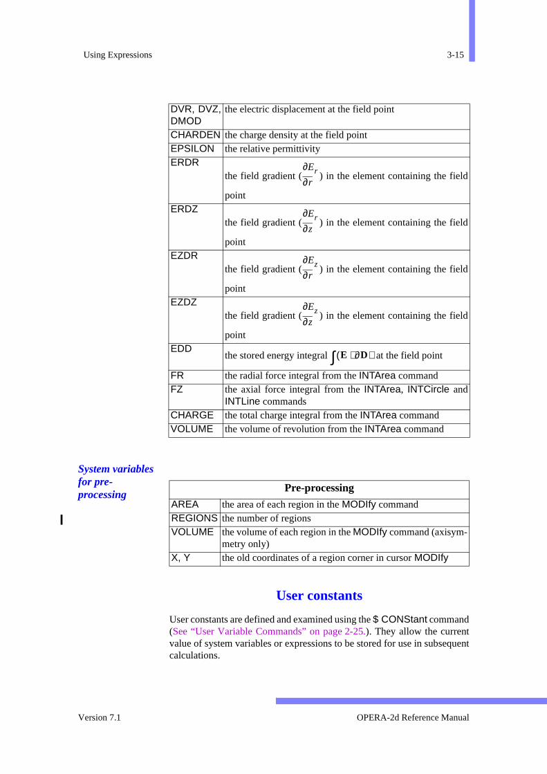
Using Expressions 3-15
quent
ld
ld
ld
ld
System variables for pre-processing
User constants
User constants are defined and examined using the $ CONStant command(See “User Variable Commands” on page 2-25.). They allow the currentvalue of system variables or expressions to be stored for use in subsecalculations.
DVR, DVZ,DMOD
the electric displacement at the field point
CHARDEN the charge density at the field pointEPSILON the relative permittivityERDR
the field gradient ( ) in the element containing the fie
pointERDZ
the field gradient ( ) in the element containing the fie
pointEZDR
the field gradient ( ) in the element containing the fie
pointEZDZ
the field gradient ( ) in the element containing the fie
pointEDD
the stored energy integral at the field point
FR the radial force integral from the INTArea commandFZ the axial force integral from the INTArea, INTCircle and
INTLine commandsCHARGE the total charge integral from the INTArea commandVOLUME the volume of revolution from the INTArea command
r∂∂Er
z∂∂Er
r∂∂Ez
z∂∂Ez
E ∂D⋅( )∫
Pre-processing
AREA the area of each region in the MODIfy commandREGIONS the number of regionsVOLUME the volume of each region in the MODIfy command (axisym-
metry only)X, Y the old coordinates of a region corner in cursor MODIfy
Version 7.1 OPERA-2d Reference Manual

3-16 Chapter 3 - The Pre and Post-Processor
theother
tinuedd in
2-nd
cur-
e
ble orr-
ntagends and
User parameters
User parameters are defined and examined using the $ PARAmeter com-mand (See “User Variable Commands” on page 2-25.). They allow expres-sions to be stored. The value of user parameters is recalculated fromexpression each time it is referenced using the current values of any parameters or variables.
Expressions
Expressions cannot exceed 75 characters, since they cannot be conon subsequent lines. Full details of the operators and functions alloweexpressions are described in “Expressions in Parameter Values” on page15. The $ PARAmeter command should be used to ‘program’ the Pre aPost-Processor if more complicated expressions are needed.
Examples
Three examples are given here.
• Example - to set the current density in a set of regions to give a totalrent of 1000 in each.
OPERA-2d > modi reg1=10 15 dens=1000/area
• Example - to evaluate rA for axisymmetric flux contours, assuming thsolution potential is A:
OPERA-2d > $ para #ra r*potDefine and store user parameters
OK
It is sometimes necessary to store the current value of a system variaexpression. The $ CONStant command copies the current value of a vaiable or expression into a user defined name. Thus to plot the percehomogeneity of the flux density along a line the following set of commacould be used. First, the field at the reference point (10,0) is calculatedstored in a constant.
• Example - to calculate the homogeneity of flux density point by meth=cart xp=10 0 $ cons #byrf by
Name Value Expression or Value
#RA 0.0 R*POT
OPERA-2d Reference Manual 27 September 1999

Using Expressions 3-17
d as aplex
ess-values
ing
the
le. For
scil-
uch
pli-
-
at
The value of BY is now assigned to the constant #BYRF. Next the homo-geneity can be calculated.
line 0 0 20 0 comp=100*(by-#byrf)/#byrf
Note that the POINt, CIRCle, LINE and CONTour commands can calcu-late homogeneity using the +HOMOgeneity, XREFerence and YREFer-ence parameters.
Field Evaluation in Steady-state AC
In Steady-state ac solutions, the magnetic vector potential is expressecomplex number at each node. The post-processor calculates a comvalue of flux density, field strength and current density. The post-procing commands can access these complex values and functions of the in 4 ways, set by the TIME parameter.
• TIME=number : this specifies an angle in degrees around the drivac cycle. Thus TIME=0 gives the in-phase component, and TIME=90gives the quadrature component.
• TIME=AMPLitude gives the amplitude of the field quantity.
• TIME=PHASe gives the phase angle of the field quantity, defined asangle at which the field quantity is maximum.
TIME=TAVErage gives the time average of the field quantity. For simpquantities, such as the potential or flux density, the time average is zero
the integrand in the energy integrals, for example , where two o
lating quantities are multiplied together, the time average is non-zero. Sfield products have the form:
(3.1)
The value of a is returned as the time average, as the am
tude, as the phase, and e as the value for a TIME=ωt.
For items such as the ‘built-in’ integrands in INTArea, INTCircle andINTLine, TIME=TAVErage is also ‘built-in’ and the integrals are evaluated correctly for any value of TIME. However, in evaluating functionsdefined by the user for the COMPonent parameter, each field quantitywithin the expression is evaluated with the value of TIME given beforeCOMPonent is evaluated and integrated. This means, for example, th
COMP=POT*J/2,TIME=TAVE
A J⋅2
-----------
e a b 2ωtcos c 2ωtsin+ +=
(b2
c2)+
cb---atan
Version 7.1 OPERA-2d Reference Manual

3-18 Chapter 3 - The Pre and Post-Processor
uch
would return a value of zero. To obtain the time average integral for sCOMPonents, 3 integrals should be performed at TIMEs 0, 45 and 90. Ifthe results are assigned to user constants #i0, #i45 and #i90, the followingcommands can be used to find the values of a, b and c as parameters #a,#b and #c and the values of the integral equivalent to AMPLitude, TAV-Erage and PHASe.• Example inta time=0 comp=j*mu*hcy$ cons #i0 integralinta time=45$ cons #i45 integralinta time=90$ cons #i90 integral$ para #a 0.5*(#i0+#i90)$ para #b 0.5*(#i0-#i90)$ para #c #i45-#a$ para #ampl sqrt(#b**2+#c**2)$ para #tave #a$ para #phas atan2(#c;#b)*180/pi
OPERA-2d Reference Manual 27 September 1999
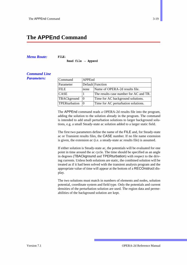
The APPEnd Command 3-19
m,andolu-d.
onengle
ill bed the
utionrrentrme-
The APPEnd Command
Menu Route: FILE ↓Read file → Append
Command Line Parameters:
The APPEnd command reads a OPERA-2d results file into the prograadding the solution to the solution already in the program. The commis intended to add small perturbation solutions to larger background stions, e.g. a small Steady-state ac solution added to a larger static fiel
The first two parameters define the name of the FILE and, for Steady-stateac or Transient results files, the CASE number. If no file name extensionis given, the extension ac (i.e. a steady-state ac results file) is assumed.
If either solution is Steady-state ac, the potentials will be evaluated forpoint in time around the ac cycle. The time should be specified as an ain degrees (TBACkground and TPERturbation) with respect to the driv-ing currents. Unless both solutions are static, the combined solution wtreated as if it had been solved with the transient analysis program anappropriate value of time will appear at the bottom of a RECOnstruct dis-play.
The two solutions must match in numbers of elements and nodes, solpotential, coordinate system and field type. Only the potentials and cudensities of the perturbation solution are used. The region data and peabilities of the background solution are kept.
Command APPEndParameter Default Function FILE none Name of OPERA-2d results file.CASE 1 The results case number for AC and TR.TBACkground 0 Time for AC background solutions.TPERturbation 0 Time for AC perturbation solutions.
Version 7.1 OPERA-2d Reference Manual
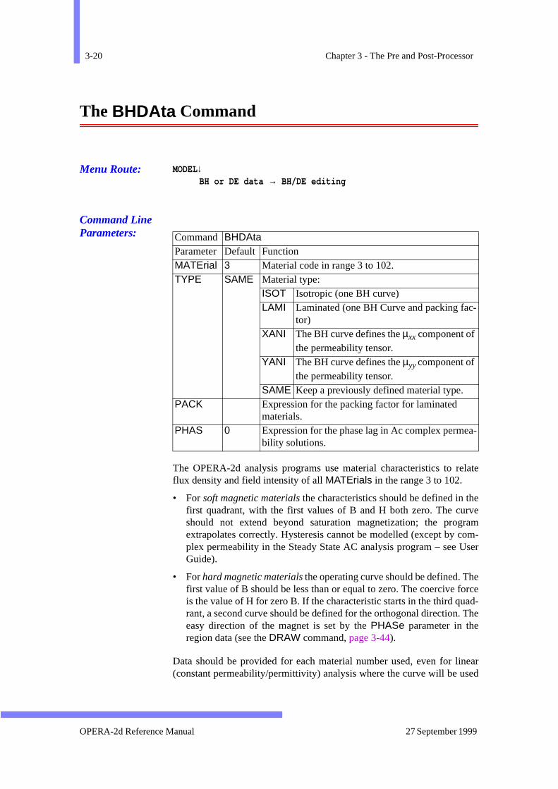
3-20 Chapter 3 - The Pre and Post-Processor
elate
erveramom-
User
eorcead- The
nearsed
-
a-
The BHDAta Command
Menu Route: MODEL↓BH or DE data → BH/DE editing
Command Line Parameters:
The OPERA-2d analysis programs use material characteristics to rflux density and field intensity of all MATErials in the range 3 to 102.
• For soft magnetic materials the characteristics should be defined in thfirst quadrant, with the first values of B and H both zero. The cushould not extend beyond saturation magnetization; the progextrapolates correctly. Hysteresis cannot be modelled (except by cplex permeability in the Steady State AC analysis program – see Guide).
• For hard magnetic materials the operating curve should be defined. Thfirst value of B should be less than or equal to zero. The coercive fis the value of H for zero B. If the characteristic starts in the third qurant, a second curve should be defined for the orthogonal direction.easy direction of the magnet is set by the PHASe parameter in theregion data (see the DRAW command, page 3-44).
Data should be provided for each material number used, even for li(constant permeability/permittivity) analysis where the curve will be u
Command BHDAta Parameter Default Function MATErial 3 Material code in range 3 to 102. TYPE SAME Material type:
ISOT Isotropic (one BH curve) LAMI Laminated (one BH Curve and packing fac
tor) XANI The BH curve defines the µxx component of
the permeability tensor. YANI The BH curve defines the µyy component of
the permeability tensor. SAME Keep a previously defined material type.
PACK Expression for the packing factor for laminated materials.
PHAS 0 Expression for the phase lag in Ac complex permebility solutions.
OPERA-2d Reference Manual 27 September 1999
The BHDAta Command 3-21
and
s ofic orntries
Hl isot-
ust
plexstate
ingg the ondataented
the vari-le let-
ssionalues
thehed.)
ry
to look up the coercive force.
In electrostatics, similar curves can be used to relate the electric fielddisplacement current.
The BHDAta command is used to create, edit or check tables of pairvalues that define the non-linear BH or DE characteristics of magnetdielectric materials. There must be at least 5 and not more than 50 ein each table. Tables can be STORed in files or LOADed from files whichare compatible with those used in other Vector Fields software.
The parameter, MATErial, specifies the material number to which the Bcurve applies. Other parameters must be selected to set the materiaropy type. If a laminated material is being used, a PACKing factor must begiven. If an anisotropic material is required two separate BH curves mbe given.
The PHASe parameter can be used to give an expression for the comphase lag when using the complex permeability option of the Steady-AC Analysis Program.
On entering the BHDAta command, the user is presented with the existBH curve or an empty set of axes. Points can be added or edited usinBHDAta command’s 8 sub-commands. These allow addition of pointsthe current curve, modification of existing points, access to files, and checking. The sub-commands have named parameters but are documhere assuming positional parameter input in the correct order. Indescription below the sub-commands are given in upper case and theable values in lower case. Sub-commands can be abbreviated to singters. In any case only the first 4 characters are decoded.
In the REPLace sub-command, the values of the parameters B and H areset to the current values for the point being replaced, before any exprefor them is decoded. This allows expressions to be used to reset the vof B and H in terms of their old values.
• Example: to ‘dilute’ a BH curve; note use of the command loop andboolean parameter, -REDRaw, which prevents re-drawing the grapafter each replace command. (In this example, cgs units are assum
OP2-BHDA > $ do #i 1 23OP2-BHDA > r #i h+(b-h)*0.9 h -redrOP2-BHDA > $ end do
A library of BH data files is supplied with the software in directo$VFDIR/bh (UNIX) or %VFDIR%\bh (Windows).
Version 7.1 OPERA-2d Reference Manual
3-22 Chapter 3 - The Pre and Post-Processor
-
eticswithme
odel.
nly.
ctro-ng)atedsion
pic).
ata
e-ith
ts
BHDAta Sub-commands
The sub-commands of the BHDAta command are described in the following table:
Anisotropy in OPERA-2d
It is possible to use anisotropic materials in most of the electromagnanalysis programs of OPERA-2d. The choice of material type is stored the BH curve for each material. A combination of some isotropic, solaminated and some anisotropic materials is possible within a single mSelection of material type is made from within the BHDAta command.
• All solvers are able to solve problems using isotropic materials oThe solutions can be either linear or non-linear.
• Models using laminated materials can be analysed using all the elemagnetics solvers except the transient or velocity (with upwindisolvers. The analysis can be either linear or non-linear. For laminmaterials a packing factor must be given. This can be an expresusing only the system variables X, Y, R or Z which should evaluate tonumbers between 0 (equivalent to air) and 1 (equivalent to isotro
Sub-commands
Function
ADD b h Add a new point to the end of the table. band h arenumeric values of B and H.
CHECk m n Check the data and display the interpolations of the dused in analysis. m and n specify the first and last pointdisplayed.
DELEte m n Deletes the points m to n of the curve. n can have thevalue * to indicate the last point.
INSErt n b h Inserts a new point after the nth point of the curve. band h are numeric values of B and H.
LIST Lists the material type, packing factor, complex permability phase lag and BH data points associated wthat material.
LOAD file Loads a curve from a file. The file name extension bh isadded to the name if no extension is given. Any poinalready defined are deleted.
QUIT Leave the BHDAta command. REPLace n b h Replaces the nth point of the curve. b and h are the new
values of B and H. ±REDRaw can be used to controlwhether the curve is re-displayed.
STORE file Stores the curve in a file. The file name extension bh isadded to the name if no extension is given.
OPERA-2d Reference Manual 27 September 1999
The BHDAta Command 3-23
rial
hanal
-
scal-
on,es,
ceptt be
cal-
to the
The direction of the normal to the laminations is given by the mateproperty, PHASe.
• Laminated materials have an effective permeability that is lower tthe isotropic permeability, and which is different in the planes normand tangential to the laminations.
(3.2)
(3.3)
where p is the packing factor, µ is the isotropic permeability of the material.
The coercivity of laminated permanent magnets is also reduced by ing by the packing factor.
• Anisotropic materials require 2 BH curves, one for the local X directione for the local Y direction. The direction of the local X and Y axrelative to the global, is given by the PHASe property for each region.All the electromagnetics solvers can use anisotropic materials extransient and velocity when upwinding is used. The analysis musnon-linear.
Note that the modulus of the field strength or flux density is used to culate the permeability for both directions.
The stress, thermal and space charge solvers ignore all reference material type.
µnormal µ* 1 p–( ) p+=
µtangential µ* p 1 p–( )+=
Version 7.1 OPERA-2d Reference Manual

3-24 Chapter 3 - The Pre and Post-Processor
s can
e
r of
ja-
The CHECk Command
Menu Route: MODEL↓Mesh generator → Check region data
Command Line Parameters:
The CHECk command checks the region and mesh data. Some checkonly be made after the mesh has been generated by the MESH command.The CHECk command is run automatically after thMESH ERROr=YES command (page 3-128), but can be run at othertimes as well.
The following checks are made:
• Region data: consistency between MATErial code and properties.
• BH data: do BH curves exist for each material?
• Eddy current conductors: uniform conductivity and current density.
• Elements: non-zero areas.
• Boundary conditions: at least one node with assigned potential.
• Solution: matching numbers of nodes and elements.
• Symmetry boundaries: are they all paired?
Some checks result in warnings, others in errors. If the total numbeerrors is non-zero, the mesh cannot be stored.
The TEST command (page 3-166) does geometric checks between adcent regions.
Command CHECkNo Parameters
OPERA-2d Reference Manual 27 September 1999
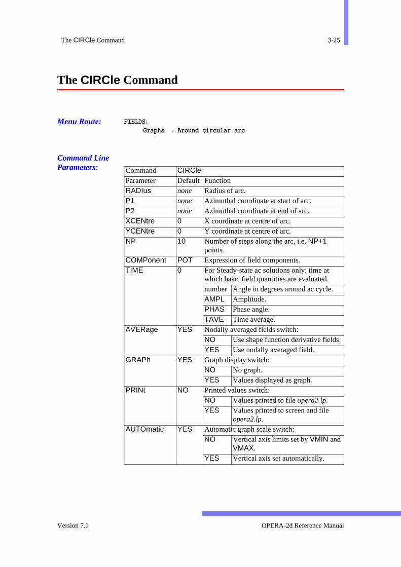
The CIRCle Command 3-25
The CIRCle Command
Menu Route: FIELDS↓Graphs → Around circular arc
Command Line Parameters:
Command CIRCle Parameter Default FunctionRADIus none Radius of arc. P1 none Azimuthal coordinate at start of arc. P2 none Azimuthal coordinate at end of arc. XCENtre 0 X coordinate at centre of arc. YCENtre 0 Y coordinate at centre of arc. NP 10 Number of steps along the arc, i.e. NP+1
points. COMPonent POT Expression of field components. TIME 0 For Steady-state ac solutions only: time at
which basic field quantities are evaluated. number Angle in degrees around ac cycle. AMPL Amplitude. PHAS Phase angle. TAVE Time average.
AVERage YES Nodally averaged fields switch: NO Use shape function derivative fields.YES Use nodally averaged field.
GRAPh YES Graph display switch: NO No graph. YES Values displayed as graph.
PRINt NO Printed values switch: NO Values printed to file opera2.lp. YES Values printed to screen and file
opera2.lp. AUTOmatic YES Automatic graph scale switch:
NO Vertical axis limits set by VMIN and VMAX.
YES Vertical axis set automatically.
Version 7.1 OPERA-2d Reference Manual
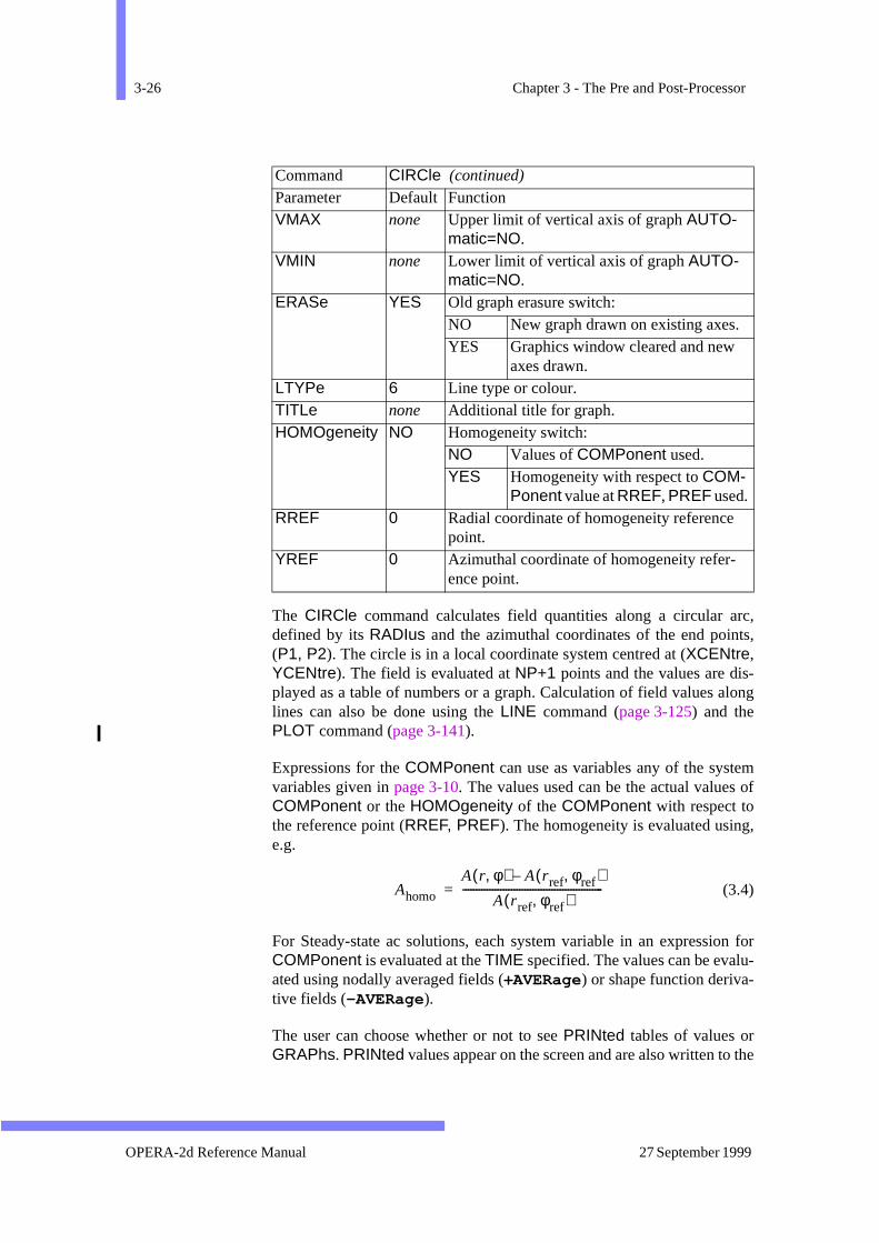
3-26 Chapter 3 - The Pre and Post-Processor
rc,ts,
-long
m of
,
n for-
the
The CIRCle command calculates field quantities along a circular adefined by its RADIus and the azimuthal coordinates of the end poin(P1, P2). The circle is in a local coordinate system centred at (XCENtre,YCENtre). The field is evaluated at NP+1 points and the values are displayed as a table of numbers or a graph. Calculation of field values alines can also be done using the LINE command (page 3-125) and thePLOT command (page 3-141).
Expressions for the COMPonent can use as variables any of the systevariables given in page 3-10. The values used can be the actual valuesCOMPonent or the HOMOgeneity of the COMPonent with respect tothe reference point (RREF, PREF). The homogeneity is evaluated usinge.g.
(3.4)
For Steady-state ac solutions, each system variable in an expressioCOMPonent is evaluated at the TIME specified. The values can be evaluated using nodally averaged fields (+AVERage) or shape function deriva-tive fields (-AVERage).
The user can choose whether or not to see PRINted tables of values orGRAPhs. PRINted values appear on the screen and are also written to
VMAX none Upper limit of vertical axis of graph AUTO-matic=NO.
VMIN none Lower limit of vertical axis of graph AUTO-matic=NO.
ERASe YES Old graph erasure switch: NO New graph drawn on existing axes. YES Graphics window cleared and new
axes drawn. LTYPe 6 Line type or colour. TITLe none Additional title for graph. HOMOgeneity NO Homogeneity switch:
NO Values of COMPonent used. YES Homogeneity with respect to COM-
Ponent value at RREF, PREF used. RREF 0 Radial coordinate of homogeneity reference
point. YREF 0 Azimuthal coordinate of homogeneity refer-
ence point.
Command CIRCle (continued) Parameter Default Function
Ahomo
A r φ,( ) A rref φref,( )–
A rref φref,( )----------------------------------------------------=
OPERA-2d Reference Manual 27 September 1999
The CIRCle Command 3-27
et
dis--urs
ede
ys-
dialogue file opera2.lp. The graphs can have the vertical axis limits sAUTOmatically or by the values of VMAX and VMIN with -AUTO-matic .
Multiple graphs can be displayed on the same axes, the first beingplayed with +ERASe, and the rest with -ERASe. The graphs can be displayed with different line styles (on monochrome displays) or colo(LTYPe), and a TITLe in addition to the COMPonent can be added to thekey below the graph. The TITLe is not remembered and must be supplieach time it is needed. TITLes including spaces or commas should benclosed in quotation marks (’ ).
The MINIMUM and MAXIMUM values along the arc are assigned to stem variables.
Version 7.1 OPERA-2d Reference Manual
3-28 Chapter 3 - The Pre and Post-Processor
ate itblesre not
dkault
The CLEAr Command
Menu Route: OPTIONS↓Clear and Reset
Command Line Parameters:
The CLEAr command puts the Pre and Post-Processor back to the stwas in when it first started. It deletes all the data, re-initializes all variaand sets all parameters back to their default values. User variables adeleted.
If a file called opera2.comi exists in the current file directory, it is openeand read as a $ COMInput file (see page 2-28) before control passes bacto the user. This allows the user to supply an individual choice of defvalues for commands such as COLOur (page 3-29) and UNITs (page 3-173) or define frequently used $ CONStants and $ PARAmeters(page 2-25).
CommandCLEArNo Parameters
OPERA-2d Reference Manual 27 September 1999
The COLOur Command 3-29
used
n beTheged.
thislay).
or
The COLOur Command
Menu Route: OPTIONS↓Colour settings
Command Line Parameters:
The COLOur command enables the user to change any of the colours for the display. This can be done in two ways:
• the colour map numbers associated with the parts of the display care-assigned (this only has an effect if the picture is re-displayed). colour numbers associated with materials 13 to 102 cannot be chan
• the definition of a colour map number, CODE, in terms of the RED,GREEn and BLUE components can be changed (on most displays, has an immediate effect, if the colour number appears on the dispRED, GREEn and BLUE should each be in the range 0 to 1.
If a value of CODE is given, the current values of the colour map f
Command COLOur Parameter Default Function C0 3 Colour map number for material 0. C1 4 Colour map number for material 1. C3 6 Colour map number for material 3. C4 7 Colour map number for material 4. C5 8 Colour map number for material 5. C6 9 Colour map number for material 6. C7 10 Colour map number for material 7. C8 11 Colour map number for material 8. C9 12 Colour map number for material 9. C10 13 Colour map number for material 10. C11 14 Colour map number for material 11. C12 15 Colour map number for material 12. CMAP 5 Colour map number for line contour maps. CTEXt 1 Colour map number for text and axes. CODE 1 Colour map number to be redefined. * can
be used for last contour colour.RED none Amount of red for colour CODE. GREEn none Amount of green for colour CODE. BLUE none Amount of blue for colour CODE.
Version 7.1 OPERA-2d Reference Manual

3-30 Chapter 3 - The Pre and Post-Processor
s.
ur willweentrum.
nd) con-loursiallyt; on
y and
ult
CODE are displayed. If values are also given for RED, GREEn or BLUE,then the colour map for CODE is redefined. The current values of RED,GREEn and BLUE can be used in expressions to define the new value
If the value of CODE corresponds to either the first of last contour colo(16 and 230 on most displays with 256 colours), all the contour coloursbe changed to give a rainbow of colours or a variation of shades betthe colour specified and the existing colour at the other end of the specCODE=* can be used to specify the last contour colour.
On a 16 colour display, with colour map numbers 0 (the backgrouthrough 15, the colours 7 through 15 are also used for coloured zonetour maps. On displays with more than 16 colours, a separate set of co(≥ 16) is used for coloured zone contours. On some displays, especthose with less than 16 colours, the default colour numbers are differenothers it may not be possible to change the colour map.
The menu colours are separate from the colours used for the displacannot be re-defined.
WARNING: changing colours can make the display invisible. The defacolours can be reinstated with the DEVIce command (seepage 3-39).
OPERA-2d Reference Manual 27 September 1999
The COMOutput Command 3-31
st- in the
ach
hing
ssaryave
k into
ong
The COMOutput Command
Menu Route: FILE ↓Write file → Commands out
Command Line Parameters:
The COMOutput writes a file containing the minimum set of Pre and PoProcessor commands necessary to recreate the region data currentlyprogram. The commands included are SET, UNITs, TEST and a DRAWcommand for each region. Finally, GROUp commands are included torestore the region group definitions. A comment is inserted before eDRAW command giving the region number. The TEST -DRAW commandis included with the assumption that the regions already match. Switcoff the testing allows the file to be read much more quickly.
If any of the regions are polygons, the keyboard sub-commands neceto recreate them are written to the file. Any construction lines which hbeen defined will be included as well.
If a FILE with no file name extension is given, the extension comi isassumed. The file may be edited with the system editor and read bacthe Pre and Post-Processor using the $ COMInput command (see page 2-28), In particular, the LENGth parameter of the UNITs command can bechanged in order to scale data which was originally input in the wrunits.
Command COMOutput Parameter Default Function FILE none Name of command file.
Version 7.1 OPERA-2d Reference Manual
3-32 Chapter 3 - The Pre and Post-Processor
The CONTour Command
Menu Route: FIELDS↓Contour plot
Command Line Parameters: Command CONTour
Parameter Default FunctionCOMPonent POT Field component for contours. LINEs 10 Number of lines or zones TIME 0 For Steady-state ac solutions only: time at
which basic field quantities are evaluated. number Angle in degrees around ac cycle. AMPL Amplitude. PHAS Phase angle. TAVE Time average.
ERASe NO Picture erase switch: NO Old picture not erased. YES Old picture erased.
LABEl YES Contour labelling: NO No labels. NUMB Lines labelled with index numbers or
colour scale shown. YES Lines labelled with index numbers or
colour scale shown. VALU Lines labelled with line values or col-
our scale shown. AUTOmatic YES Automatic contour value switch:
NO Line values set by STARt, FINIsh and INCRement.
YES Line values set automatically by LINEs and the part of the model on the display.
STARt 0 Value of first line for AUTOmatic=NO. FINIsh 0 Value of last line for AUTOmatic=NO. INCRement 0 Increment between lines for AUTOmatic=NO. STYLe LINE Contouring style:
COLO Coloured line contours LINE Monochrome line contours
OPERA-2d Reference Manual 27 September 1999

The CONTour Command 3-33
e-eob-
fh
t
2
o
The CONTour command draws contours of field quantities. The paramters allow the user to choose the STYLe, to set the number of lines and thvalues and to limit contouring to specific materials or regions of the prlem.
Expressions for the COMPonent, VX and VY can use as variables any othe system variables given in page 3-10. For Steady-state ac solutions, eacsystem variable in an expression is evaluated at the TIME specified.
The values used for contouring can be the actual values of COMPonent orthe HOMOgeneity of the COMPonent with respect to the reference poin(XREF, YREF). The homogeneity is evaluated using, e.g.
NONE No contours (for use with DEFOrmed mesh plots
SYMB + and - symbols ZONE Coloured zone contours
REG1 1 Regions to be contoured. number Regions in range REG1 to REG2. group Regions in group named.
REG2 * Last region to be contoured. * for highest region number.
MATErial ALL Material number to be contoured: 0, 1, 3 to 10or ALL.
NOT ANY Material number not to be contoured: 0, 1, 3 t102 or ANY.
HOMOgeneity NO Homogeneity switch: NO Values of COMPonent used. YES Homogeneity with respect to COM-
Ponent value at XREF, YREF. XREF 0 X or R coordinate of homogeneity reference
point. YREF 0 Y or Z coordinate of homogeneity reference
point. DEFOrmed NO Deformed mesh switch:
NO Use correct nodal coordinates. YES Add VX to X coordinates and VY to
Y coordinates. VX BX Field component for offset to X coordinates. VY BY Field component for offset to Y coordinates.
Command CONTour (continued)
Parameter Default Function
Version 7.1 OPERA-2d Reference Manual

3-34 Chapter 3 - The Pre and Post-Processor
mbers
f
e of
on so
with
-milar
eldson-
(3.5)
The areas to be contoured can be restricted by region and material nuor by region group name using the parameters REG1, REG2, MATErialand NOT (see page 3-109).
The system variables MINIMUM and MAXIMUM are set with the values othe first and last contour values.
Line contours
Line contours are selected with STYLe=LINE or STYLe=COLOur.
The values of the contour lines can be set automatically from the rangvalues on the part of the model displayed (+AUTOmatic ) and the numberof LINEs or manually (-AUTOmatic ) by setting the STARting value, theFINIshing value and INCRement between the lines. If INCRement=0the number of LINEs is used.
In +AUTOmatic mode, LINEs specifies the minimum number of lines tbe drawn. An increment of 1, 2 or 5 times a power of 10 will be chosethat the number of lines is ≥ LINEs. However, if LINEs is negative, or thecalculated number of lines would be > 100, then precisely |LINEs| will bedrawn.
The contour line numbers can be switched on or off with +LABEl and -LABEl . Alternatively, the value of each contour can be used as a label LABEl=VALUe.
Line contours can be drawn in one colour (STYLe=LINE ) or in many col-ours (STYLe=COLOur). COLOured line contours are drawn with the colours available for zones so that if many lines are used the effect is sito STYLe=ZONE.
The use of some system variables (such as ERROR, the field gradients andthe material properties) within the expression for COMPonent will lead tofields which are discontinuous from one element to the next. Such fimay be impossible to view with line contours since few if any of the ctours will cross the elements. Coloured ZONE contours will show thesefields correctly.
Ahomo
A x y,( ) A xref yref,( )–
A xref yref,( )---------------------------------------------------=
OPERA-2d Reference Manual 27 September 1999
The CONTour Command 3-35
(
set
with
n byA
(
r may
Coloured zone contours
Coloured zone contours are selected with STYLe=ZONE.
The values of coloured zone contours can be set automatically (+AUTO-matic ) from the values on the part of the model displayed or manually-AUTOmatic ) from the values of STARt and FINIsh. In both cases LINEsspecifies the number of zones. The maximum number of zones isaccording to the capability of the graphics hardware (see page 3-29).
A scale showing the values corresponding to the colour is displayed +LABEl .
Symbols
Symbol contours are selected with STYLe=SYMBol. A + or – symbol isdrawn at the centroid of each element. The size of the symbols is givethe values of COMPonent; they are drawn in the current length units. scaling factor may have to be included in the expression for COMPonentto adjust the size of the symbols.
The range of values used for symbols can be set automatically (+AUTO-matic ) from the values on the par of the model displayed or manually-AUTOmatic ) from the values of STARt and FINIsh. In both cases LINEsis ignored.
Deformed mesh plots
Deformed mesh plots are selected with +DEFOrmed.
Contouring is performed on a deformed mesh, with the value of VX evalu-ated at each node added to the X coordinates of the nodes and VY evaluatedat each node added to the Y coordinates of the nodes. A scaling factohave to be included in the expressions for VX and VY to adjust the size ofthe deformation.
Deformed meshes can be displayed without contours using STYLe=NONE.
Version 7.1 OPERA-2d Reference Manual

3-36 Chapter 3 - The Pre and Post-Processor
ions.g
he
ularular
usefulcu-
The CONVert Command
Menu Route: MODEL↓Change regions
Command Line Parameters:
The CONVert command changes the shape code of 3 and 4 sided regThe regions to be CONVerted are given by number or group name usinparameters REG1 and REG2 (see page 3-109). The new shape code bySHAPe.
Any region with shape C, CS, H or Q can be converted to shape BACK-ground or POLYgon. This allows additional points to be inserted using tMODIfy cursor sub-command I.
OPERA-2d can either automatically mesh regions, producing an irregmesh of elements, or regularly mesh quadrilateral regions. The regmeshing gives the user greater control of the element shape, and is for demanding applications (for example modelling skin effects acrately).
Four sided POLYgons can be converted to shapes H or Q, which create aregular mesh.
Command CONVert Parameter Default Function REG1 none Regions to be converted.
number Regions in range REG1 to REG2. group Regions in group named.
REG2 none Last region to be converted. * for highest regionnumber.
SHAPe none New shape code: BACKground, H, Q or POLYgon.
OPERA-2d Reference Manual 27 September 1999

The COPY Command 3-37
r or
laced
ave
The COPY Command
Menu Route: MODEL↓Copy regions
Command Line Parameters:
The COPY command makes copies of regions, specified by numbegroup name using parameters REG1 and REG2 (see page 3-109). The fol-lowing coordinate transformations are made to form the new regions:
• rotation through an angle THETa with respect to local coordinate origin
• reflection in a mirror plane at an angle THETa through the local coor-dinate origin
• displacement by DX in the x direction
• displacement by DY in the y direction
A mirror image is created with +MIRRor ; a rotated copy is made with -MIRRor .
Regions of shapes C and CS are displaced by adding DX and DY to theirlocal coordinate system origin (XCEN, YCEN), i.e. the displacement iswith respect to the global coordinate system. Other shapes are dispwith respect to their local coordinate systems.
The COPY command creates new regions which can be modified to hdifferent material properties or coordinates. The DRAW and MODIfy com-
Command COPY Parameter Default Function REG1 none Regions to be copied.
number Regions in range REG1 to REG2. group Regions in group named.
REG2 none Last region to be copied. * for highest region number.
DX 0 X displacement. DY 0 Y displacement. THETa 0 Angle of rotation or mirror plane. MIRRor YES Mirror reflection or rotation switch.
NO THETa gives rotation angle. YES THETa gives angle of mirror plane.
Version 7.1 OPERA-2d Reference Manual

3-38 Chapter 3 - The Pre and Post-Processor
- but
mands (page 3-43 and page 3-130) have replication parameters which create copies of regions with displacements, rotations and reflections,retaining the same material properties for all copies.
OPERA-2d Reference Manual 27 September 1999
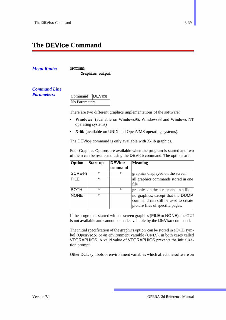
The DEVIce Command 3-39
T
two
ym-lled
on
e
e
The DEVIce Command
Menu Route: OPTIONS↓Graphics output
Command Line Parameters:
There are two different graphics implementations of the software:
• Windows (available on Windows95, Windows98 and Windows Noperating systems)
• X-lib (available on UNIX and OpenVMS operating systems).
The DEVIce command is only available with X-lib graphics.
Four Graphics Options are available when the program is started andof them can be reselected using the DEVIce command. The options are:
If the program is started with no screen graphics (FILE or NONE), the GUIis not available and cannot be made available by the DEVIce command.
The initial specification of the graphics option can be stored in a DCL sbol (OpenVMS) or an environment variable (UNIX), in both cases caVFGRAPHICS. A valid value of VFGRAPHICS prevents the initializa-tion prompt.
Other DCL symbols or environment variables which affect the software
Command DEVIceNo Parameters
Option Start-up DEVIce command
Meaning
SCREen * * graphics displayed on the screenFILE * all graphics commands stored in on
fileBOTH * * graphics on the screen and in a fileNONE * no graphics, except that the DUMP
command can still be used to creatpicture files of specific pages.
Version 7.1 OPERA-2d Reference Manual
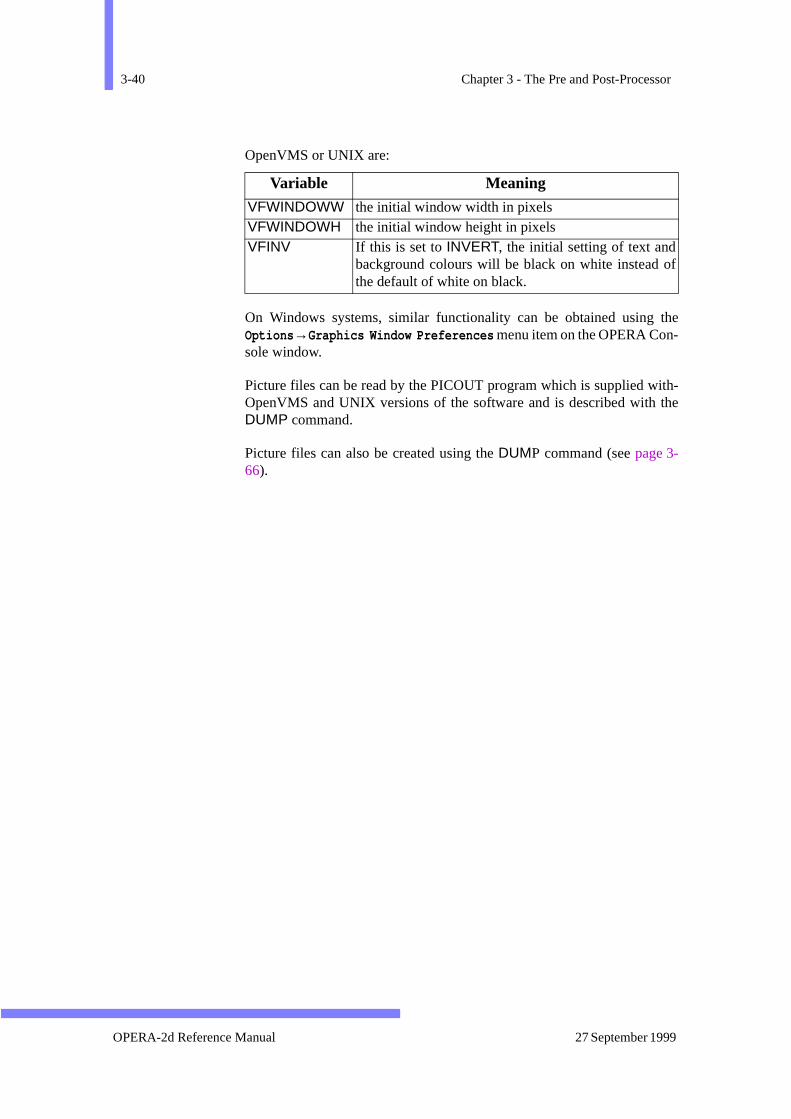
3-40 Chapter 3 - The Pre and Post-Processor
the-
ith-the
f
OpenVMS or UNIX are:
On Windows systems, similar functionality can be obtained using Options →Graphics Window Preferences menu item on the OPERA Console window.
Picture files can be read by the PICOUT program which is supplied wOpenVMS and UNIX versions of the software and is described with DUMP command.
Picture files can also be created using the DUMP command (see page 3-66).
Variable Meaning
VFWINDOWW the initial window width in pixelsVFWINDOWH the initial window height in pixelsVFINV If this is set to INVERT, the initial setting of text and
background colours will be black on white instead othe default of white on black.
OPERA-2d Reference Manual 27 September 1999

The DIMEnsion Command 3-41
.
The DIMEnsion Command
Menu Route: OPTIONS↓Dimension
Command Line Parameters:
Command DIMEnsion Parameter Default FunctionOPTIon SHOW Options:
ARC Define an arc in polar coordinates. DELE. Delete dimensions. LINE Define a line in cartesian coordi-
nates. LIST List dimensions. SHOW Display dimensions.
X1 0 X coordinate at start of line. Y1 0 Y coordinate at start of line. X2 0 X coordinate at end of line. Y2 0 Y coordinate at end of line. CURVature 0 Curvature of a line. XCENtre 0 X coordinate at centre of arc. YCENtre 0 Y coordinate at centre of arc. RADIus 0 Radius of arc. ANGLe 0 Azimuthal coordinate at start of arc. THETa 0 Angle subtended by the arc. LTYPe 0 Line style for dimension line. 0 is solid; 1, 2, 3
... are broken. LABEl none Label to be written at centre of dimension lineXLABel 0 Offset in X direction from centre of dimension
line for the label. YLABel 0 Offset in Y direction from centre of dimension
line for the label. ARROw FORWard Type of arrows:
BACK Pointing towards the start of thedimension line.
BOTH Arrows at both ends of the line. FORW Pointing to the end of the dimension
line. NONE No arrows.
Version 7.1 OPERA-2d Reference Manual
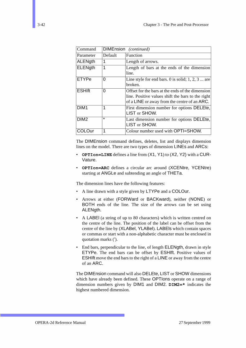
3-42 Chapter 3 - The Pre and Post-Processor
ion
ing
on the
ed in
f
n
e
nt
The DIMEnsion command defines, deletes, list and displays dimenslines on the model. There are two types of dimension LINEs and ARCs:
• OPTIon=LINE defines a line from (X1, Y1) to (X2, Y2) with a CUR-Vature.
• OPTIon=ARC defines a circular arc around (XCENtre, YCENtre)starting at ANGLe and subtending an angle of THETa.
The dimension lines have the following features:
• A line drawn with a style given by LTYPe and a COLOur.
• Arrows at either (FORWard or BACKward), neither (NONE) orBOTH ends of the line. The size of the arrows can be set usALENgth.
• A LABEl (a string of up to 80 characters) which is written centredthe centre of the line. The position of the label can be offset fromcentre of the line by (XLABel, YLABel). LABEls which contain spacesor commas or start with a non-alphabetic character must be enclosquotation marks (’).
• End bars, perpendicular to the line, of length ELENgth, drawn in styleETYPe. The end bars can be offset by ESHIft. Positive values ofESHIft move the end bars to the right of a LINE or away from the centreof an ARC.
The DIMEnsion command will also DELEte, LIST or SHOW dimensionswhich have already been defined. These OPTIons operate on a range odimension numbers given by DIM1 and DIM2. DIM2=* indicates thehighest numbered dimension.
ALENgth 1 Length of arrows. ELENgth 1 Length of bars at the ends of the dimensio
line. ETYPe 0 Line style for end bars. 0 is solid; 1, 2, 3 ... ar
broken. ESHIft 0 Offset for the bars at the ends of the dimensio
line. Positive values shift the bars to the righof a LINE or away from the centre of an ARC.
DIM1 1 First dimension number for options DELEte,LIST or SHOW.
DIM2 * Last dimension number for options DELEte,LIST or SHOW.
COLOur 1 Colour number used with OPTI=SHOW.
Command DIMEnsion (continued)
Parameter Default Function
OPERA-2d Reference Manual 27 September 1999
The DRAW Command 3-43
g thelane.
f the
that
llow-
ic.
ubdi-
et of addi-t the
aluesxt,
M)leheepa-e the
The DRAW Command
The geometry of a device to be analysed by OPERA-2d is defined usinDRAW command as a set of polygonal areas or regions of the 2d pOne region can be a BACKground region which covers the whole problemspace. Other regions must not overlap each other but can lie on top oBACKground region if it exists.
Regions (except for the background region) can have replications sorepeated structures can be defined easily.
In magnetic devices, for example, a region can represent one of the foing:
• free-space;
• a conductor with a prescribed or induced current density;
• permeable material with a linear or non-linear material characterist
Within each region mesh generation is automatic, based only on the svision of the sides (or faces). There are 6 different region SHAPe codeswhich can be divided into 2 classes: quadrilaterals and polygons. The s60 parameters only includes parameters for four sided regions, so antional set of sub-commands, keyboard or cursor, must be used to inpucoordinates and face properties of polygons.
Since the parameters are initialized to sensible default values and the vused for one DRAW command become the default values for the nemany less than 60 values need to be given with each command.
Background regions are defined with SHAPe=BACKground but in otherrespects they are defined in the same way as polygons.
The gap regions of rotating machines (for analysis using OPERA-2d/Rshould be defined with SHAPE=GAP. The gap region should be a singpolygon consisting of two concentric circles. All the points defining tregion should be on either the inner or outer circle. The gap region srates the stationary and moving parts of the model. The regions insidgap region are given the rotational velocity (See “The SOLVe Command”on page 3-157.).
There are obvious advantages in using polygonal regions, including:
• Smaller number of regions.
• Cursor input and automatic matching to existing regions.
The quadrilateral regions have some uses as well:
Version 7.1 OPERA-2d Reference Manual
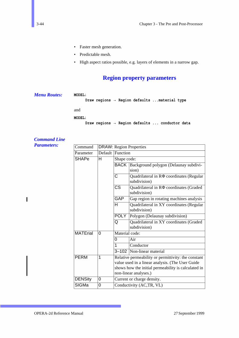
3-44 Chapter 3 - The Pre and Post-Processor
.
• Faster mesh generation.
• Predictable mesh.
• High aspect ratios possible, e.g. layers of elements in a narrow gap
Region property parameters
Menu Routes: MODEL↓Draw regions → Region defaults ...material type
and
MODEL↓Draw regions → Region defaults ... conductor data
Command Line Parameters:
Command DRAW: Region Properties Parameter Default Function SHAPe H Shape code:
BACK Background polygon (Delaunay subdivi-sion)
C Quadrilateral in RΦ coordinates (Regular subdivision)
CS Quadrilateral in RΦ coordinates (Graded subdivision)
GAP Gap region in rotating machines analysisH Quadrilateral in XY coordinates (Regular
subdivision) POLY Polygon (Delaunay subdivision) Q Quadrilateral in XY coordinates (Graded
subdivision) MATErial 0 Material code:
0 Air 1 Conductor 3–102 Non-linear material
PERM 1 Relative permeability or permittivity: the constantvalue used in a linear analysis. (The User Guide shows how the initial permeability is calculated innon-linear analyses.)
DENSity 0 Current or charge density. SIGMa 0 Conductivity (AC,TR, VL)
OPERA-2d Reference Manual 27 September 1999
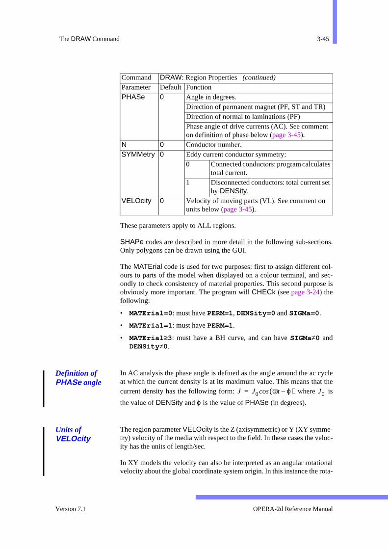
The DRAW Command 3-45
ns.
ol- sec-se is
cyclet theis
loc-
onalota-
t
s
t
These parameters apply to ALL regions.
SHAPe codes are described in more detail in the following sub-sectioOnly polygons can be drawn using the GUI.
The MATErial code is used for two purposes: first to assign different cours to parts of the model when displayed on a colour terminal, andondly to check consistency of material properties. This second purpoobviously more important. The program will CHECk (seepage 3-24) thefollowing:
• MATErial=0 : must have PERM=1, DENSity=0 and SIGMa=0.
• MATErial=1 : must have PERM=1.
• MATErial ≥3: must have a BH curve, and can have SIGMa≠0 andDENSity ≠0.
Definition of PHASe angle
In AC analysis the phase angle is defined as the angle around the acat which the current density is at its maximum value. This means thacurrent density has the following form: where
the value of DENSity and ϕ is the value of PHASe (in degrees).
Units of VELOcity
The region parameter VELOcity is the Z (axisymmetric) or Y (XY symme-try) velocity of the media with respect to the field. In these cases the veity has the units of length/sec.
In XY models the velocity can also be interpreted as an angular rotativelocity about the global coordinate system origin. In this instance the r
PHASe 0 Angle in degrees. Direction of permanent magnet (PF, ST and TR)Direction of normal to laminations (PF) Phase angle of drive currents (AC). See commenon definition of phase below (page 3-45).
N 0 Conductor number. SYMMetry 0 Eddy current conductor symmetry:
0 Connected conductors: program calculatetotal current.
1 Disconnected conductors: total current seby DENSity.
VELOcity 0 Velocity of moving parts (VL). See comment on units below (page 3-45).
Command DRAW: Region Properties (continued)
Parameter Default Function
J J0 ωt ϕ–( )cos= J0
Version 7.1 OPERA-2d Reference Manual

3-46 Chapter 3 - The Pre and Post-Processor
as
y
e
axes,
meters
ad-
an be
tional velocity is still unit converted, and the velocity should be definedω/LENGU
Coordinates of SHAPes H and Q
Command Line Parameters:
These parameters apply to SHAPes H and Q only.
SHAPes H and Q are curvilinear quadrilaterals in XY coordinates. Theare defined by the local coordinates of the 4 corners (X1, Y1, ... X4, Y4),and the curvatures of the faces (P1, ... P4, described below under FacProperties, page 3-49).
For regions which are rectangular and parallel to the major coordinate additional parameters are supplied: e.g. X12 sets X1 and X2 simultane-ously. If X12 is specified it overrides any values for X1 and X2 given indi-vidually on the same command and the default values of X1 and X2 forsubsequent commands. The same rules apply to the other paired para(X34, Y14 and Y23).
The subdivision of the regions is defined by the parameters N1, N2, N3and N4, B1, B2, B3 and B4 described later under Face Properties (page 3-49). For SHAPe=H the numbers of elements on opposite faces of the qurilateral is equal and is defined by N1 and N2. For SHAPe=Q the numbersof elements on one pair of opposite faces is equal, and the mesh cgraded between the other pair of faces. In other words, either N1=N3 orN2=N4 must be satisfied.
Command DRAW: H and Q coordinates Parameter Default Function X12 none X1 and X2. X34 none X3 and X4. Y14 none Y1 and Y4. Y23 none Y2 and Y3. X1 0 X coordinate of corner 1. Y1 0 Y coordinate of corner 1. X2 0 X coordinate of corner 2. Y2 0 Y coordinate of corner 2. X3 0 X coordinate of corner 3. Y3 0 Y coordinate of corner 3. X4 0 X coordinate of corner 4. Y4 0 Y coordinate of corner 4.
OPERA-2d Reference Manual 27 September 1999
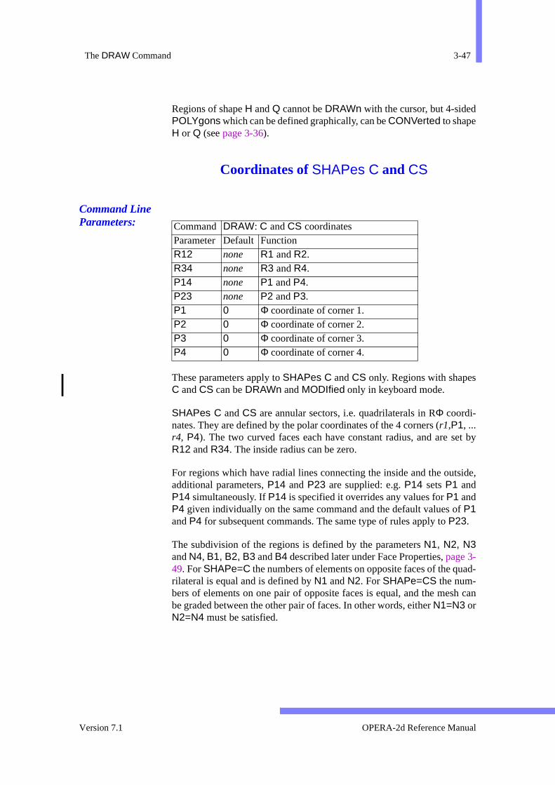
The DRAW Command 3-47
et by
side,
f
ad-
h can
Regions of shape H and Q cannot be DRAWn with the cursor, but 4-sidedPOLYgons which can be defined graphically, can be CONVerted to shapeH or Q (see page 3-36).
Coordinates of SHAPes C and CS
Command Line Parameters:
These parameters apply to SHAPes C and CS only. Regions with shapesC and CS can be DRAWn and MODIfied only in keyboard mode.
SHAPes C and CS are annular sectors, i.e. quadrilaterals in RΦ coordi-nates. They are defined by the polar coordinates of the 4 corners (r1,P1, ...r4, P4). The two curved faces each have constant radius, and are sR12 and R34. The inside radius can be zero.
For regions which have radial lines connecting the inside and the outadditional parameters, P14 and P23 are supplied: e.g. P14 sets P1 andP14 simultaneously. If P14 is specified it overrides any values for P1 andP4 given individually on the same command and the default values oP1and P4 for subsequent commands. The same type of rules apply to P23.
The subdivision of the regions is defined by the parameters N1, N2, N3and N4, B1, B2, B3 and B4 described later under Face Properties, page 3-49. For SHAPe=C the numbers of elements on opposite faces of the qurilateral is equal and is defined by N1 and N2. For SHAPe=CS the num-bers of elements on one pair of opposite faces is equal, and the mesbe graded between the other pair of faces. In other words, either N1=N3 orN2=N4 must be satisfied.
Command DRAW: C and CS coordinates Parameter Default Function R12 none R1 and R2. R34 none R3 and R4. P14 none P1 and P4. P23 none P2 and P3. P1 0 Φ coordinate of corner 1. P2 0 Φ coordinate of corner 2. P3 0 Φ coordinate of corner 3. P4 0 Φ coordinate of corner 4.
Version 7.1 OPERA-2d Reference Manual

3-48 Chapter 3 - The Pre and Post-Processor
ven-orrectof al ori-is
withtions.ing
.
Local coordinates and replications
Menu Routes: MODEL↓Draw regions → Region defaults ... replications
and
MODEL↓Draw regions → Region defaults ... local coordinates
Command Line Parameters:
These parameters apply to ALL regions except the BACKground region,which cannot have replications.
The local coordinate parameters allow a region to be defined in a conient local coordinate system and then be rotated and displaced to its cposition in global coordinates. By default the local coordinate system region is identical to the global system. If it has to be changed, the locagin (XCENtre, YCENtre) and the angle from the global to local X-ax(ANGLe) may be set.
The replication parameters allow a region to have multiple copies, each copy having the same material properties and boundary condiThere are three types of replication, which are applied in the followorder: displacement in X and Y, mirror imaging, rotations. The COPYcommand also creates copies of regions; new regions created by COPYing
Command DRAW: Local coordinates and replications Parameter Default FunctionXCENtre 0 X coordinate of local origin. YCENtre 0 Y coordinate of local origin. ANGLe 0 Angle from global X axis to local X axis. NX 1 Number of replications with X displacement. NY 1 Number of replications with Y displacement. DX 0 X displacement between replications. DY 0 Y displacement between replications. MIRRor NO Mirror reflection switch.
NO No mirror copy. YES Copy reflected in mirror plane.
TMIRror 0 Angle of mirror plane through local coordinate ori-gin.
ROT 1 Number of replications with rotational displacementTROT 0 Angle between rotational replications.
OPERA-2d Reference Manual 27 September 1999

The DRAW Command 3-49
n-
d by.
urva-de to 4
ndary it is
can be MODIfied to have different material properties and boundary coditions (see page 3-37 and page 3-130).
The displacements in X and Y are defined by the number of copies (NX andNY) and the displacement between each copy (DX and DY). This creates atotal of NX*NY copies including the original.
Mirror images are selected with +MIRRor. The geometry is reflected in aplane through the local coordinate origin rotated by TMIRror from the localX axis.
Rotational images are defined by the number of copies (ROT) and the azi-muthal displacement between each copy (TROT).
All the replications are performed in the local coordinate system.
Face properties
Command Line Parameters:
These parameters only apply to the regularly meshed regions defineSHAPE=Q,H,C or CS. In the following table n can take the values 1 to 4
These parameters do not apply to polygons.
The face parameters set the boundary conditions, subdivisions and ctures (SHAPes H and Q only) of quadrilateral regions. Face 1 is the sifrom corners 1 to 2, face 2 from corners 2 to 3, face 3 from corners 3and face 4 from corners 4 to 1.
There are 4 types of boundary conditions set by the parameters Fn. Regionfaces which are internal to the mesh usually should be assigned boucondition NO. This can also be used on the outside of the mesh where
Command DRAW: Face properties (not polygons) Parameter Default Function Fn NO Type of boundary condition for face n:
DV Normal derivative of potential = DVn. NO Internal face. SYMM One of symmetry (periodicity) pair. V Value of potential = Vn.
Vn 0 Value of potential if Fn=V. DVn 0 Normal derivative of potential if Fn=DV. Nn 1 Number of elements along face n. Bn 0.5 Subdivision bias for face n. Pn 0 Curvature of face n (SHAPes H and Q).
Version 7.1 OPERA-2d Reference Manual
3-50 Chapter 3 - The Pre and Post-Processor
d
ositenfor- pro-
ters
s.
se
of thet. The
inoros-enf the
ith
ordi-mand
t it
equivalent to Fn=DV DVn=0. Boundaries with a fixed potential shoulhave Fn=V with the value of potential set by Vn. Pairs of faces withFn=SYMMetry can be connected by the SYMMetry command (page 3-164) to have either the same potential, or the same magnitude but oppsign. The sections in the User Guide on the analysis programs give imation on which boundary conditions can be used with each analysisgram.
The subdivision of a region into elements is specified by the parameN1, ..., N4 and B1, ..., B4. The numbers of subdivisions (N1,...N4) spec-ify the number of elements along each face. N3 and N4 are ignored forSHAPes C and H which have equal subdivision on opposite faceSHAPes CS and Q must have either N1=N3 or N2=N4, i.e. one pair ofopposite faces has the same subdivision. The parameters Bn specify a biasfor the subdivision. If Bn=0.5, there will be Nn equal sized element edgealong face n. If Bn≠0.5, the node positions vary quadratically along thface. A bias less than 0.5 has smaller elements nearer the first point face. A bias greater than 0.5 has smaller elements nearer the last poinmaximum effect of the bias can be achieved with Bn=0 or Bn=1.
The curvatures of faces of SHAPes H and Q are specified by P1,...,P4.The curvature is the reciprocal of radius. Curved lines are always marcs and follow a path to the left of the straight line if the curvature is pitive, and to the right if it is negative, the direction of the line being givin the definition of the faces above. The curvature can only be seen isubdivision is greater than 1.
POLYgon , BACKground and GAP Region Input
Menu Routes: MODEL↓Draw regions → Polygon Draw regions → BackgroundDraw regions → Rotating m/c Air Gap
The parameters described in page 3-44 and page 3-49 only supply regionproperties, local coordinates and replications for regions wSHAPe=POLYgon, SHAPe=BACKground or SHAPE=GAP. A set ofsub-commands, keyboard and cursor, is provided for inputting the conates and face properties of polygons. There is a keyboard sub-comfor switching to CURSor mode and a cursor sub-command K for switchingto keyboard mode. The program is initially in keyboard mode, buremembers any change of mode for subsequent DRAW commands.
OPERA-2d Reference Manual 27 September 1999

The DRAW Command 3-51
d
Sub-commands and Menu Items
DRAW Polygon Keyboard Sub-commandsSub-command Menu Item Function CARTesian XY input Give coordinates of next point (X,Y) in
polygon and define properties of the face created.
POLAr RT input Give coordinates of next point (R,Φ) in polygon and define properties of the face created.
XSHIft X move Continue polygon by a line in the X direction and define properties of the face created.
YSHIft Y move Continue polygon by a line in the Y direction and define properties of the face created.
RSHIft R move Continue polygon by a line in the R direction and define properties of the face created.
PSHIft T move Continue polygon by a line in the Φ direction and define properties of the face created.
FINIsh Close polygon Close and store a polygon, defining properties of the last face.
ERASe Back-track Erase the most recent point or face of the polygon being entered.
CURSor Mouse input Switch to cursor input of points, with construction lines and automatic matching to existing regions.
QUIT Return Leave the DRAW command. If there is an unfinished polygon, the user is asketo confirm the QUIT.
ZOOM Zoom display Re-display the picture, zooming in or out.
LINE Enter C_lines Define a straight construction line. ARC Enter C_lines Define a circular arc construction line. CIRCle Enter C_lines Define circular construction line(s).
Version 7.1 OPERA-2d Reference Manual
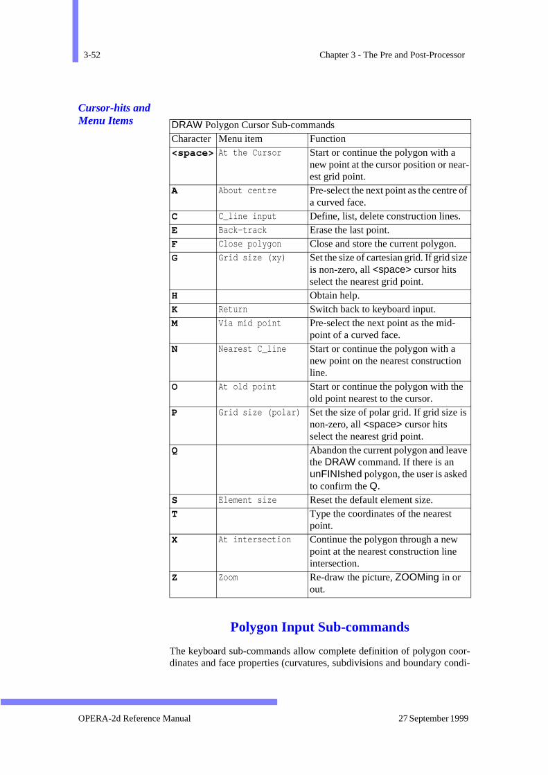
3-52 Chapter 3 - The Pre and Post-Processor
or-ondi-
r-
f
e
Cursor-hits and Menu Items
Polygon Input Sub-commands
The keyboard sub-commands allow complete definition of polygon codinates and face properties (curvatures, subdivisions and boundary c
DRAW Polygon Cursor Sub-commandsCharacter Menu item Function <space> At the Cursor Start or continue the polygon with a
new point at the cursor position or neaest grid point.
A About centre Pre-select the next point as the centre oa curved face.
C C_line input Define, list, delete construction lines. E Back-track Erase the last point. F Close polygon Close and store the current polygon. G Grid size (xy) Set the size of cartesian grid. If grid size
is non-zero, all <space> cursor hits select the nearest grid point.
H Obtain help. K Return Switch back to keyboard input. M Via mid point Pre-select the next point as the mid-
point of a curved face. N Nearest C_line Start or continue the polygon with a
new point on the nearest construction line.
O At old point Start or continue the polygon with the old point nearest to the cursor.
P Grid size (polar) Set the size of polar grid. If grid size isnon-zero, all <space> cursor hits select the nearest grid point.
Q Abandon the current polygon and leavthe DRAW command. If there is an unFINIshed polygon, the user is askedto confirm the Q.
S Element size Reset the default element size. T Type the coordinates of the nearest
point. X At intersection Continue the polygon through a new
point at the nearest construction line intersection.
Z Zoom Re-draw the picture, ZOOMing in or out.
OPERA-2d Reference Manual 27 September 1999

The DRAW Command 3-53
eseother
nly. Sub-
newe
in a
r
-
-
tions). Seven of the sub-commands, CARTesian, POLAr, XSHIft,YSHIft, RSHIft, PSHIft and FINIsh have parameters CURVature, N,BIAS, F, V and DV. When any of these sub-commands sets any of thparameters, the values given become the default values for all the sub-commands. These parameters are described in full under the CARTe-sian sub-command.
In keyboard mode, a polygon must be started by a CARTesian or POLArsub-command, giving the initial coordinates. This first sub-command odefines a point and the parameters for the face properties are ignoredsequent sub-commands CARTesian, POLAr, XSHIft, YSHIft, RSHIft orPSHIft define a point and a face connecting the previous point to the one. Polygons must be closed by a FINIsh sub-command which defines thlast face of the polygon.
The ARC Sub-command
Menu Route: MODEL↓Draw regions → Draw Polygon →Enter C_lines
Draw Background →Enter C_linesDraw Rotating m/c Air Gap →Enter C_lines
Command Line Parameters:
The ARC sub-command creates a construction line: a straight line polar coordinate system centered on (XCENtre, YCENtre).It starts at (R1,P1) and extends to (R2, P2). If R1 and R2 are the same, the line will bean arc of a circle. If P1 and P2 are the same, it will be a radial line. Furthedetails on the use of construction lines are give in page 3-64.
Sub-Command ARCParameter Default Function XCENtre 0 X coordinate at centre of polar coordinate sys
tem. YCENtre 0 Y coordinate at centre of polar coordinate sys
tem. R1 0 R coordinate at start of line. P1 0 Φ coordinate at start of line. R2 0 R coordinate at end of line. P2 0 Φ coordinate at end of line.
Version 7.1 OPERA-2d Reference Manual
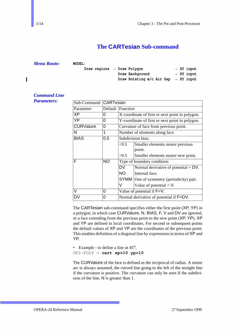
3-54 Chapter 3 - The Pre and Post-Processor
ointst.
or linedivi-
The CARTesian Sub-command
Menu Route: MODEL↓Draw regions → Draw Polygon → XY input
Draw Background → XY inputDraw Rotating m/c Air Gap → XY input
Command Line Parameters:
The CARTesian sub-command specifies either the first point (XP, YP) ina polygon, in which case CURVature, N, BIAS, F, V and DV are ignored,or a face extending from the previous point to the new point (XP, YP). XPand YP are defined in local coordinates. For second or subsequent pthe default values of XP and YP are the coordinates of the previous poinThis enables definition of a diagonal line by expressions in terms of XP andYP.
• Example - to define a line at 45o: OP2-POLY > cart xp+10 yp+10
The CURVature of the face is defined as the reciprocal of radius. A minarc is always assumed, the curved line going to the left of the straightif the curvature is positive. The curvature can only be seen if the subsion of the line, N is greater than 1.
Sub-Command CARTesian Parameter Default Function XP 0 X-coordinate of first or next point in polygon. YP 0 Y-coordinate of first or next point in polygon. CURVature 0 Curvature of face from previous point. N 1 Number of elements along face. BIAS 0.5 Subdivision bias:
<0.5 Smaller elements nearer previous point.
>0.5 Smaller elements nearer new point. F NO Type of boundary condition:
DV Normal derivative of potential = DV. NO Internal face. SYMM One of symmetry (periodicity) pair. V Value of potential = V.
V 0 Value of potential if F=V. DV 0 Normal derivative of potential if F=DV.
OPERA-2d Reference Manual 27 September 1999
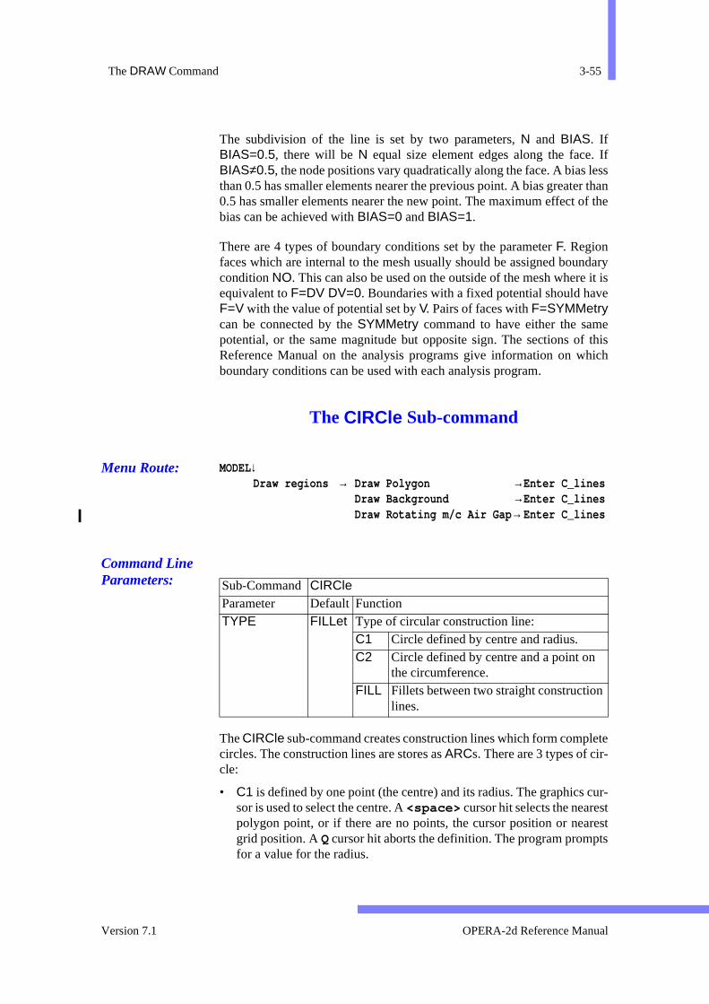
The DRAW Command 3-55
. Iflessr thanf the
ndary it ise
ef thishich
lete
cur-trestts
The subdivision of the line is set by two parameters, N and BIAS. IfBIAS=0.5, there will be N equal size element edges along the faceBIAS≠0.5, the node positions vary quadratically along the face. A bias than 0.5 has smaller elements nearer the previous point. A bias greate0.5 has smaller elements nearer the new point. The maximum effect obias can be achieved with BIAS=0 and BIAS=1.
There are 4 types of boundary conditions set by the parameter F. Regionfaces which are internal to the mesh usually should be assigned boucondition NO. This can also be used on the outside of the mesh whereequivalent to F=DV DV=0. Boundaries with a fixed potential should havF=V with the value of potential set by V. Pairs of faces with F=SYMMetrycan be connected by the SYMMetry command to have either the sampotential, or the same magnitude but opposite sign. The sections oReference Manual on the analysis programs give information on wboundary conditions can be used with each analysis program.
The CIRCle Sub-command
Menu Route: MODEL↓Draw regions → Draw Polygon →Enter C_lines
Draw Background →Enter C_linesDraw Rotating m/c Air Gap → Enter C_lines
Command Line Parameters:
The CIRCle sub-command creates construction lines which form compcircles. The construction lines are stores as ARCs. There are 3 types of cir-cle:
• C1 is defined by one point (the centre) and its radius. The graphicssor is used to select the centre. A <space> cursor hit selects the nearespolygon point, or if there are no points, the cursor position or neagrid position. A Q cursor hit aborts the definition. The program prompfor a value for the radius.
Sub-Command CIRCle Parameter Default Function TYPE FILLet Type of circular construction line:
C1 Circle defined by centre and radius. C2 Circle defined by centre and a point on
the circumference. FILL Fillets between two straight construction
lines.
Version 7.1 OPERA-2d Reference Manual
3-56 Chapter 3 - The Pre and Post-Processor
ondtrest
es.
d, andines
put.
the
• C2 is defined by two points: the first defines the centre and the seca point on the circumference. <space> cursor hits select the nearespolygon points, or if there are no points, the cursor positions or neagrid positions. A Q cursor hit aborts the definition.
• FILLets are circles tangential to intersecting straight construction linThey are defined by selecting the two straight lines using <space>cursor hits. A Q cursor hit aborts the definition. Four circles are defineeach one consisting of two construction lines, which are the majorminor arcs connecting the points where the circles and straight ltouch.
Further details on the use of construction lines are give in page 3-64.
The CURSor Sub-command
Menu Route: MODEL↓Draw regions → Draw Polygon → Mouse input
Draw Background → Mouse inputDraw Rotating m/c Air Gap → Mouse input
Command Line Parameters:
The CURSor sub-command switches from keyboard input to cursor inof polygons. The cursor sub-command K can be used to switch back again
The parameter SIZE selects the default element size. This is used to setnumber of subdivisions on non-matching region faces. N is given thesmallest integer such that N*SIZE is greater than the length of the face.
The ERASe Sub-command
Menu Route: MODEL↓Draw regions → Draw Polygon → Back-track
Draw Background → Back-trackDraw Rotating m/c Air Gap → Back-track
Sub-Command CURSor Parameter Default Function SIZE 1 Default element size.
OPERA-2d Reference Manual 27 September 1999
The DRAW Command 3-57
pol-
tingface
puthe
Command Line Parameters:
The ERASe sub-command erases the most recent point or face of theygon being entered.
The FINIsh Sub-command
Menu Route: MODEL↓Draw regions → Draw Polygon → Close polygon
Draw Background → Close polygonDraw Rotating m/c Air Gap → Close polygon
Command Line Parameters:
The FINIsh sub-command creates the last face of a polygon by connecthe last point entered to the first point. The parameters specify the properties of the last face. The polygon is stored.
Control remains with the polygon input sub-command mode for the inof more polygons. The QUIT sub-command should be used to leave tDRAW command.
The parameters CURVature, N, BIAS, F, V and DV are defined under theCARTesian sub-command.
The LINE Sub-command
Menu Route: MODEL↓Draw regions → Draw Polygon →Enter C_lines
Draw Background →Enter C_linesDraw Rotating m/c Air Gap → Enter C_lines
Sub-Command ERASeNo Parameters
Sub-Command FINIsh Parameters CURVature, N, BIAS, F, V and DV as in CARTesian sub-command.
Version 7.1 OPERA-2d Reference Manual

3-58 Chapter 3 - The Pre and Post-Processor
om
ori-
the
Command Line Parameters:
The LINE sub-command creates a construction line: a straight line fr(X1, Y1) to (X2, Y2) rotated by ANGLe around (X1, Y1). Further detailson the use of construction lines are give in page 3-64.
The POLAr Sub-command
Menu Route: MODEL↓Draw regions → Draw Polygon → RT input
Draw Background → RT inputDraw Rotating m/c Air Gap → RT input
Command Line Parameters:
The POLAr sub-command specifies either the first point (RP, PP) in a pol-ygon, in which case CURVature, N, BIAS, F, V and DV are ignored, or aface extending from the previous point to the new point (RP, PP). RP andPP are defined in polar coordinates with respect to the local coordinategin. For second or subsequent points the default values of RP and PP arethe coordinates of the previous point. This enables the definition ofcoordinates of the next point by expressions in terms of RP and PP.
The parameters CURVature, N, BIAS, F, V and DV are defined under theCARTesian sub-command.
Sub-Command LINE Parameter Default Function X1 0 X coordinate at start of line. Y1 0 Y coordinate at start of line. X2 0 X coordinate at end of line. Y2 0 Y coordinate at end of line. ANGLe 0 Rotation angle around start point.
Sub-Command POLAr Parameter Default Function RP 0 Radial coordinate of first or next point in poly-
gon. PP 0 Φ-coordinate of first or next point in polygon. CURVature, N, BIAS, F, V and DV as in CARTesian sub-command
OPERA-2d Reference Manual 27 September 1999
The DRAW Command 3-59
of a the the
The PSHIft Sub-command
Menu Route: MODEL↓Draw regions → Draw Polygon → T move
Draw Background → T moveDraw Rotating m/c Air Gap → T move
Command Line Parameters:
The PSHIft sub-command specifies the second or subsequent point polygon in terms of an increment in the local azimuthal coordinate ofpoint with respect to the previous point. The radial coordinate remainssame as that of the previous point.
The parameters CURVature, N, BIAS, F, V and DV are defined under theCARTesian sub-command.
The QUIT Sub-command
Menu Route: MODEL↓Draw regions → Draw Polygon → Return
Draw Background → ReturnDraw Rotating m/c Air Gap → Return
Command Line Parameters:
The QUIT sub-command leaves the DRAW command. If there is an unfin-ished polygon, the user is asked to confirm the QUIT.
Sub-Command PSHIft Parameter Default Function DP 0 Increment in Φ-coordinate for next point in pol-
ygon. CURVature, N, BIAS, F, V and DV as in CARTesian sub-command.
Sub-Command QUITNo Parameters
Version 7.1 OPERA-2d Reference Manual
3-60 Chapter 3 - The Pre and Post-Processor
of aoint the
of aith
-
The RSHIft Sub-command
Menu Route: MODEL↓Draw regions → Draw Polygon → R move
Draw Background → R moveDraw Rotating m/c Air Gap → R move
Command Line Parameters:
The RSHIft sub-command specifies the second or subsequent point polygon in terms of an increment in the local radial coordinate of the pwith respect to the previous point. The azimuthal coordinate remainssame as that of the previous point.
The parameters CURVature, N, BIAS, F, V and DV are defined under theCARTesian sub-command.
The XSHIft Sub-command
Menu Route: MODEL↓Draw regions → Draw Polygon → X move
Draw Background → X moveDraw Rotating m/c Air Gap → X move
Command Line Parameters:
The XSHIft sub-command specifies the second or subsequent point polygon in terms of an increment in the local X coordinate of the point w
Sub-Command RSHIft Parameter Default Function DR 0 Increment in R-coordinate for next point in pol
ygon. CURVature, N, BIAS, F, V and DV as in CARTesian sub-command.
Sub-Command XSHIft Parameter Default Function DX 0 Increment in X-coordinate for next point in pol-
ygon. CURVature, N, BIAS, F, V and DV as in CARTesian sub-command.
OPERA-2d Reference Manual 27 September 1999

The DRAW Command 3-61
hat of
of aith
hat of
respect to the previous point. The Y coordinate remains the same as tthe previous point.
The parameters CURVature, N, BIAS, F, V and DV are defined under theCARTesian sub-command.
The YSHIft Sub-command
Menu Route: MODEL↓Draw regions → Draw Polygon → Y move
Draw Background → Y moveDraw Rotating m/c Air Gap → Y move
Command Line Parameters:
The YSHIft sub-command specifies the second or subsequent point polygon in terms of an increment in the local Y coordinate of the point wrespect to the previous point. The X coordinate remains the same as tthe previous point.
The parameters CURVature, N, BIAS, F, V and DV are defined under theCARTesian sub-command.
The ZOOM Sub-command
Menu Route: MODEL↓Draw regions → Draw Polygon → Zoom display
Draw Background → Zoom displayDraw Rotating m/c Air Gap → Zoom display
Command Line Parameters:
Sub-Command YSHIft Parameter Default Function DY 0 Increment in Y-coordinate for next point in pol-
ygon. CURVature, N, BIAS, F, V and DV as in CARTesian sub-command.
Command ZOOMNo Parameters
Version 7.1 OPERA-2d Reference Manual

3-62 Chapter 3 - The Pre and Post-Processor
they,
oly-
olar
alsoet
it -
ubdi-ub-
thet
onal
-oft
istinggions
The ZOOM sub-command is identical to the top-level command of same name (see page 3-183). It re-displays the picture of the geometrzooming in or out.
Polygon Input Cursor Sub-commands
Menu Routes: MODEL↓Draw regions → Draw Polygon → Mouse Input
MODEL↓Draw regions → Draw Background → Mouse Input
and
MODEL↓Draw regions → Draw Rotating m/c Air Gap → Mouse Input
The cursor sub-commands allow the definition of the next point in a pgon in three ways: a new point at the cursor position (cursor hit <space> ),an existing point (cursor hit O), or a construction line point (cursor hits Nand X). Polygons are closed and stored with F.
A ‘snap to grid’ facility can be switched on by setting the cartesian or pgrid size greater than zero. When the grid is switched on, all <space> cur-sor hits take the nearest grid point. Switching on a cartesian grid switches off a polar grid and vice versa. The grid sizes can be set or re-sfollowing a G or P cursor hit.
Other cursor hits allow points to be erased (E) or their current coordinatesdisplayed (T), or keyboard mode can be used instead after cursor hK.Construction line input follows a cursor hit C. The picture can be re-displayed using the Z cursor hit which uses the ZOOM command (see page 3-183). The DRAW command can be left by cursor hit Q.
In cursor mode, if a new face exactly matches an existing face, the svision and curvature information is copied from the existing face. The sdivision of new faces (which do not match existing faces) is given byelement SIZE parameter of the CURSor keyboard sub-command or reseby the S cursor sub-command. Curvature can be set by using additipoints as the centre of curvature (cursor sub-command A) or as a mid-pointon a curve (cursor sub-command M). Such additional points are preselected using A or M; their positions can then be given using any <space> , N, O, or X; they do not form part of the polygon definition, buare only used to calculate the curvature of the face.
When a region has been completed its geometry is checked against exregions and additional points are added if necessary to make the re
OPERA-2d Reference Manual 27 September 1999
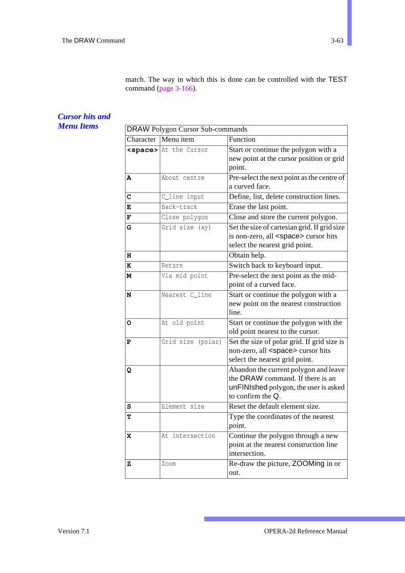
The DRAW Command 3-63
f
match. The way in which this is done can be controlled with the TESTcommand (page 3-166).
Cursor hits and Menu Items
DRAW Polygon Cursor Sub-commandsCharacter Menu item Function <space> At the Cursor Start or continue the polygon with a
new point at the cursor position or gridpoint.
A About centre Pre-select the next point as the centre oa curved face.
C C_line input Define, list, delete construction lines. E Back-track Erase the last point. F Close polygon Close and store the current polygon. G Grid size (xy) Set the size of cartesian grid. If grid size
is non-zero, all <space> cursor hits select the nearest grid point.
H Obtain help. K Return Switch back to keyboard input. M Via mid point Pre-select the next point as the mid-
point of a curved face. N Nearest C_line Start or continue the polygon with a
new point on the nearest construction line.
O At old point Start or continue the polygon with the old point nearest to the cursor.
P Grid size (polar) Set the size of polar grid. If grid size isnon-zero, all <space> cursor hits select the nearest grid point.
Q Abandon the current polygon and leavethe DRAW command. If there is an unFINIshed polygon, the user is askedto confirm the Q.
S Element size Reset the default element size. T Type the coordinates of the nearest
point. X At intersection Continue the polygon through a new
point at the nearest construction line intersection.
Z Zoom Re-draw the picture, ZOOMing in or out.
Version 7.1 OPERA-2d Reference Manual
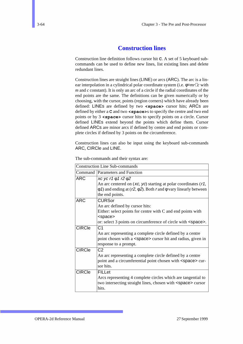
3-64 Chapter 3 - The Pre and Post-Processor
elete
ther by
been
dororm-
ands
to
Construction lines
Construction line definition follows cursor hit C. A set of 5 keyboard sub-commands can be used to define new lines, list existing lines and dredundant lines.
Construction lines are straight lines (LINE) or arcs (ARC). The arc is a lin-ear interpolation in a cylindrical polar coordinate system (i.e. φ=mr+c withm and c constant). It is only an arc of a circle if the radial coordinates ofend points are the same. The definitions can be given numerically ochoosing, with the cursor, points (region corners) which have already defined: LINEs are defined by two <space> cursor hits; ARCs aredefined by either a C and two <space> s to specify the centre and two enpoints or by 3 <space> cursor hits to specify points on a circle. Cursdefined LINEs extend beyond the points which define them. Cursdefined ARCs are minor arcs if defined by centre and end points or coplete circles if defined by 3 points on the circumference.
Construction lines can also be input using the keyboard sub-commARC, CIRCle and LINE.
The sub-commands and their syntax are:
Construction Line Sub-commands Command Parameters and Function ARC xc yc r1 φ1 r2 φ2
An arc centered on (xc, yc) starting at polar coordinates (r1, φ1) and ending at (r2, φ2). Both r and φ vary linearly between the end points.
ARC CURSor An arc defined by cursor hits: Either: select points for centre with C and end points with <space>or: select 3 points on circumference of circle with <space>.
CIRCle C1An arc representing a complete circle defined by a centre point chosen with a <space> cursor hit and radius, given in response to a prompt.
CIRCle C2An arc representing a complete circle defined by a centre point and a circumferential point chosen with <space> cur-sor hits.
CIRCle FILLetArcs representing 4 complete circles which are tangential two intersecting straight lines, chosen with <space> cursor hits.
OPERA-2d Reference Manual 27 September 1999
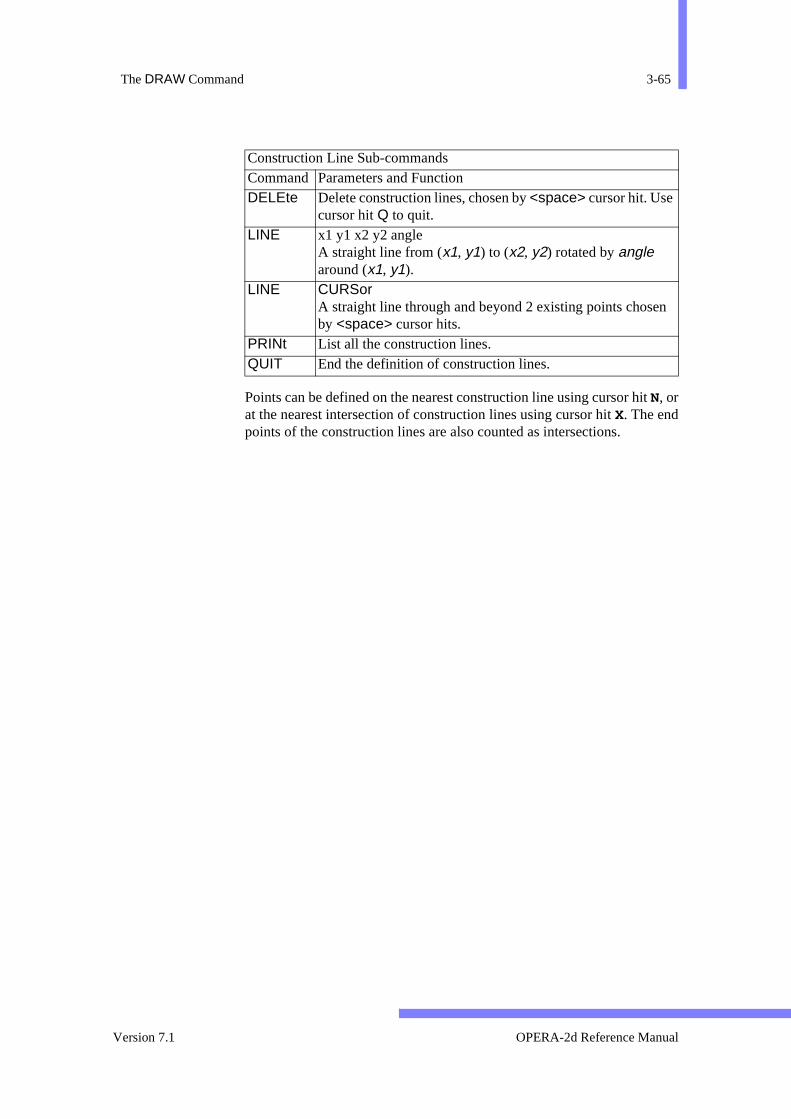
The DRAW Command 3-65
n
Points can be defined on the nearest construction line using cursor hitN, orat the nearest intersection of construction lines using cursor hit X. The endpoints of the construction lines are also counted as intersections.
DELEte Delete construction lines, chosen by <space> cursor hit. Use cursor hit Q to quit.
LINE x1 y1 x2 y2 angle A straight line from (x1, y1) to (x2, y2) rotated by angle around (x1, y1).
LINE CURSor A straight line through and beyond 2 existing points choseby <space> cursor hits.
PRINt List all the construction lines. QUIT End the definition of construction lines.
Construction Line Sub-commands Command Parameters and Function
Version 7.1 OPERA-2d Reference Manual

3-66 Chapter 3 - The Pre and Post-Processor
the-
l-
y
The DUMP Command
Menu Route: OPTIONS ↓Dump picture
Command Line Parameters:
The DUMP command dumps the graphics commands used to createcurrent display to a FILE in three different formats. If no filename extension is given, extensions .ps, .hgl or .pic are added as appropriate.
• Adobe PostScript (TYPE=POST): This has options for paper size, coour and orientation.
– There are two standard paper sizes: European A4 and American A.Alternatively SIZE=USER allows the image to be printed at an
Command DUMP Parameter Default Function FILE none Name of file to contain the picture. TYPE POST Graphics language:
HPGL Hewlett-Packard Graphics Language PICO Vector Fields PICOUT Graphics LanguagePOST Adobe PostScript
SIZE A4 Paper size:s: HPGL can use A, A3, A4, B, A0D,A1D, A2D, A3Dor A4D; PostScript can use A4, Aor USER.
LLX 0 X-coordinate of lower-left corner in mm(TYPE=POST,SIZE=USER).
LLY 0 Y-coordinate of lower-left corner in mm(TYPE=POST,SIZE=USER).
URX 0 X-coordinate of upper-right corner in mm(TYPE=POST,SIZE=USER).
URY 0 Y-coordinate of upper-right corner in mm(TYPE=POST,SIZE=USER).
COLOur YES Colour PostScript: NO implies grey-scale. FILL NO Filled polygons in HPGL: YES or NO. ORIEnt LAND PostScript paper orientation: LANDscape or POR-
trait. SWAP YES Swap black and white in PostScript:
NO Colours appear as on screen.YES Black and white are swapped.
OPERA-2d Reference Manual 27 September 1999
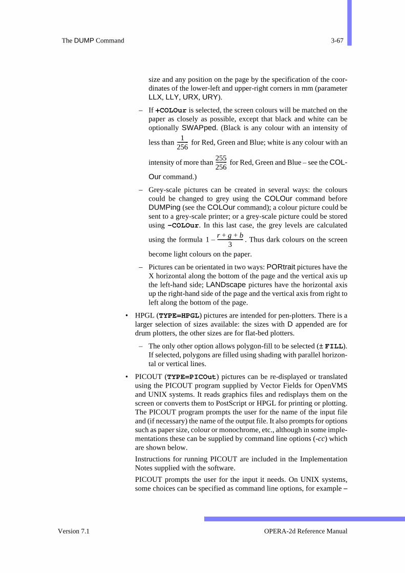
The DUMP Command 3-67
oor-eter
then bef
an
lours
eoreded
en
upst to
s a
n-
edS
theng. fileions
ple-
ion
ms,ple
size and any position on the page by the specification of the cdinates of the lower-left and upper-right corners in mm (paramLLX, LLY, URX, URY).
– If +COLOur is selected, the screen colours will be matched on paper as closely as possible, except that black and white caoptionally SWAPped. (Black is any colour with an intensity o
less than for Red, Green and Blue; white is any colour with
intensity of more than for Red, Green and Blue – see the COL-
Our command.)
– Grey-scale pictures can be created in several ways: the cocould be changed to grey using the COLOur command beforeDUMPing (see the COLOur command); a colour picture could bsent to a grey-scale printer; or a grey-scale picture could be stusing -COLOur . In this last case, the grey levels are calculat
using the formula . Thus dark colours on the scre
become light colours on the paper.
– Pictures can be orientated in two ways: PORtrait pictures have theX horizontal along the bottom of the page and the vertical axisthe left-hand side; LANDscape pictures have the horizontal axiup the right-hand side of the page and the vertical axis from righleft along the bottom of the page.
• HPGL (TYPE=HPGL) pictures are intended for pen-plotters. There ilarger selection of sizes available: the sizes with D appended are fordrum plotters, the other sizes are for flat-bed plotters.
– The only other option allows polygon-fill to be selected (± FILL ).If selected, polygons are filled using shading with parallel horizotal or vertical lines.
• PICOUT (TYPE=PICOut ) pictures can be re-displayed or translatusing the PICOUT program supplied by Vector Fields for OpenVMand UNIX systems. It reads graphics files and redisplays them onscreen or converts them to PostScript or HPGL for printing or plottiThe PICOUT program prompts the user for the name of the inputand (if necessary) the name of the output file. It also prompts for optsuch as paper size, colour or monochrome, etc., although in some immentations these can be supplied by command line options (-cc) whichare shown below.
Instructions for running PICOUT are included in the ImplementatNotes supplied with the software.
PICOUT prompts the user for the input it needs. On UNIX systesome choices can be specified as command line options, for exam–
1256---------
255256---------
1r g b+ +
3---------------------–
Version 7.1 OPERA-2d Reference Manual
3-68 Chapter 3 - The Pre and Post-Processor
out-
herin-dowrig-
ing
orfiled,ut- (
ingion out-amethis
e are
nedeing
rmat-
inald sorey.ere-y-
et is
dingfiled,me
sc below. Replies to PICOUT’s prompts can be abbreviated.
PICOUT always prompts for the name of an input file. There are 3 put options: Screen (–sc), PostScript (–ps) and HPGL (–hp).
– Screen: If output to the screen is chosen, there are no furtoptions. On workstations and X-terminals, after the graphics wdow has been created, its size can be adjusted using the winmanager and the pictures will be scaled to fit the new size. The oinal aspect ratio of the pictures will be maintained by increaseither the top or right side margin. PICOUT pauses for <carriage-return> to continue or Q to quit at the end of each picture.
– PostScript: If PostScript output is chosen, PICOUT prompts fthe name of the file to contain the PostScript program. If the already exists it will be overwritten. When PICOUT has finishethis file can be sent directly to a PostScript printer. PostScript oput can be written to multiple files with a single page in each file–s) or to one file with many pages in the file (–m). The advantage ofmultiple files is that a single page can be printed without printall the others. The filenames for the single page, multiple file optare formed by appending .1, .2, .3 etc to the name given at theput file prompt. On some operating systems, it is necessary to nthe output file with a single part name in order to make use of facility.
PostScript output can be created for different paper sizes. Ther2 standard sizes: European A4 (–a4) and American A (–a) forwhich PICOUT knows the paper size. Non-standard user defipaper sizes (–u llx lly urx ury) can also be given by specifying thcoordinates of the lower left and upper right corners of the drawarea in millimetres.
PostScript output can be orientated on the page in landscape fo(–l) or portrait format (–p). For paper sizes A and A4, portrait format fits 2 pictures on each page.
PostScript output can be in colour (–c) or greyscale (–g). Colouroutput assumes white paper, so the black and white of the origscreen picture are swapped. Greyscale intensities are invertethat dark colours appear pale grey and bright colours as dark gSome greyscale printer can interpret colour commands and thfore give a choice of using PICOUT’s algorithm for colour to grescale conversion or the printer’s algorithm.
– HPGL: If HPGL output is chosen, PICOUT prompts for the namof the file to contain the HPGL commands. Each page of outpuwritten to a separate file. The filenames are formed by appen.1, .2, .3 etc to the name given at the output file prompt. If a already exists it will be overwritten. When PICOUT has finishethe files can be sent directly to a HPGL printer or plotter. On so
OPERA-2d Reference Manual 27 September 1999

The DUMP Command 3-69
th a
flat-
izes
t thetersize)
adees
e
t-
rd
e
-
d
rkas
operating systems, it is necessary to name the output file wisimple name so that the extension can be added.
HPGL output can be created for a variety of paper sizes. For bed plotters, sizes A (–a), A3 (–a3), A4 (–a4) and B (–b) are avail-able. For drum plotters, HPGL output can be produced for sA0D (–a0d), A1D (–a1d), A2D (–a2d), A3D (–a3d) and A4D (–a4d). The difference between the flat-bed and drum sizes is thacoordinate system origin is at the centre of the plot on drum plotand at the bottom left corner on flat bed plotters. No PS (paperscommand is put into the files.
HPGL output can include extra line drawing commands to shfilled polygons (–f) or polygons can be represented by the outlinalone (-nf).
PICOUT OPTIONSOutput style:
–sc Screen. PICOUT redraws the pictures onto thworkstationscreen.
–ps PostScript. PICOUT creates a file or files of PosScript commands.
–hp HPGL. PICOUT creates files of HPGL com-mands.
Paper size (ignored with –sc): –size PostScript output can be produced for standa
papersizes A (–a) and A4 (–a4) or for a user choiceof paper size,(–ullx lly urx ury). The integer num-bers given by llx, lly, urxand uryspecify the posi-tion of the lower left and upper right corners of thpicture in millimetres.
–size[d] For flat-bed plotters, HPGL output can beproduced for sizes a, a4, a3 and b; for drum plot-ters,HPGL output can be produced for sizes a0d,a1d, a2d, a3d and a4d (d for ‘drum’.)
Polygon fill (HPGL only): –f Fill polygons (solid shading). –nf Do not fill polygons (outlines drawn).
Colour or greyscale (PostScript only): –c Colour. White paper is assumed, so black an
white are swapped. –g Greyscale. Intensities are inverted, so that da
colours appearas pale grey and bright colours dark grey.
Picture orientation (PostScript only):
Version 7.1 OPERA-2d Reference Manual

3-70 Chapter 3 - The Pre and Post-Processor
ae
–l Landscape (one picture on each page). –p Portrait (two half-size pictures on each page).
File output (PostScript only): –s Single page per file. Each picture is written to
separate file,with filenames generated from thoutput file name given by the user.
–m All pages in one file. Help:
–h For help (all other options ignored).
PICOUT OPTIONS (continued)
OPERA-2d Reference Manual 27 September 1999
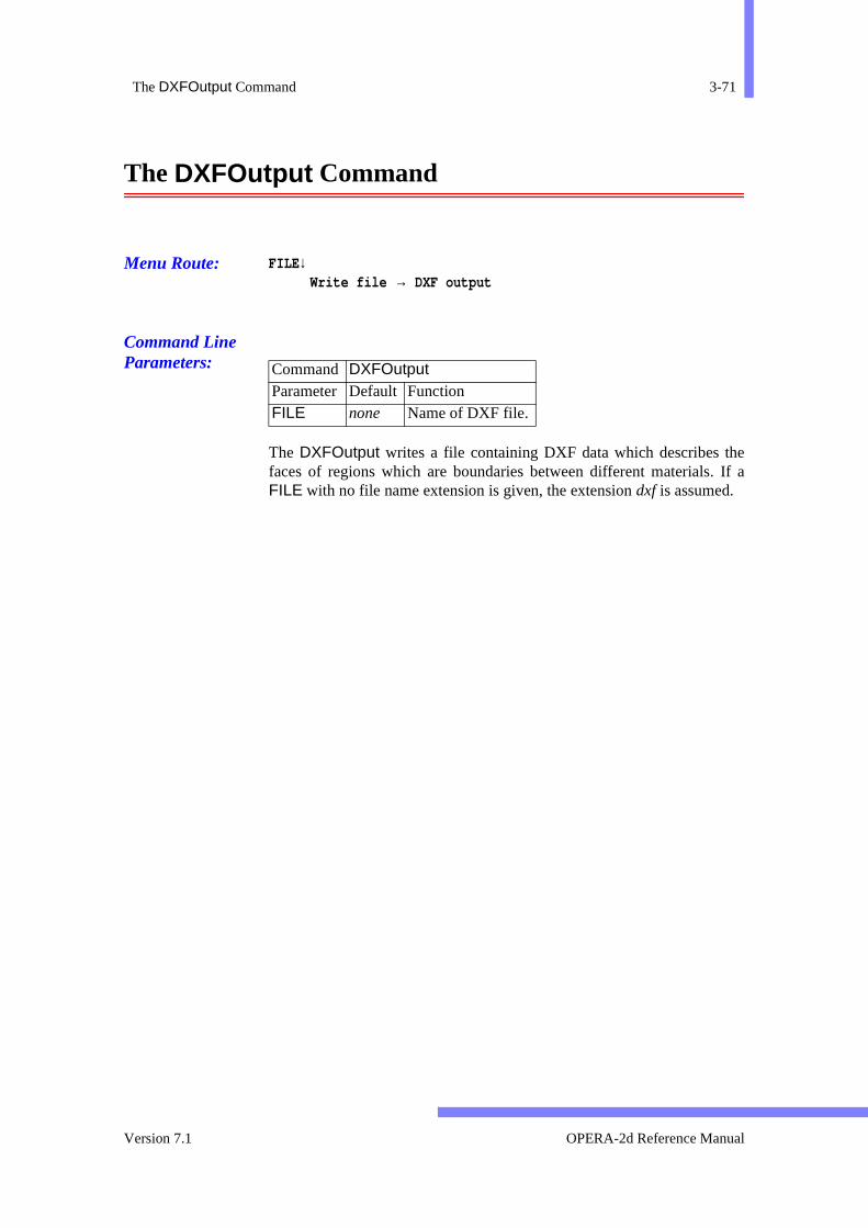
The DXFOutput Command 3-71
e If a
The DXFOutput Command
Menu Route: FILE ↓Write file → DXF output
Command Line Parameters:
The DXFOutput writes a file containing DXF data which describes thfaces of regions which are boundaries between different materials.FILE with no file name extension is given, the extension dxf is assumed.
Command DXFOutput Parameter Default Function FILE none Name of DXF file.
Version 7.1 OPERA-2d Reference Manual
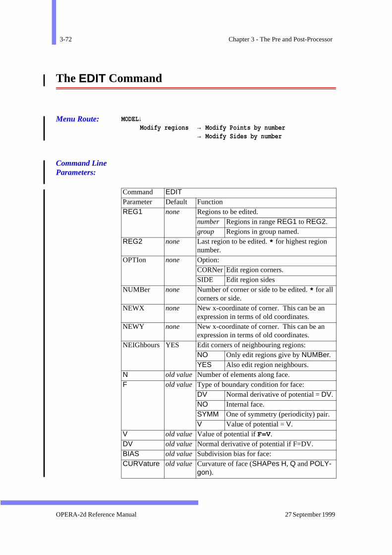
3-72 Chapter 3 - The Pre and Post-Processor
The EDIT Command
Menu Route: MODEL↓Modify regions → Modify Points by number
→ Modify Sides by number
Command Line Parameters:
Command EDITParameter Default Function REG1 none Regions to be edited.
number Regions in range REG1 to REG2. group Regions in group named.
REG2 none Last region to be edited. * for highest region number.
OPTIon none Option:CORNer Edit region corners.SIDE Edit region sides
NUMBer none Number of corner or side to be edited. * for all corners or side.
NEWX none New x-coordinate of corner. This can be an expression in terms of old coordinates.
NEWY none New x-coordinate of corner. This can be an expression in terms of old coordinates.
NEIGhbours YES Edit corners of neighbouring regions:NO Only edit regions give by NUMBer.YES Also edit region neighbours.
N old value Number of elements along face. F old value Type of boundary condition for face:
DV Normal derivative of potential = DV. NO Internal face. SYMM One of symmetry (periodicity) pair. V Value of potential = V.
V old value Value of potential if F=V. DV old value Normal derivative of potential if F=DV. BIAS old value Subdivision bias for face: CURVature old value Curvature of face (SHAPes H, Q and POLY-
gon).
OPERA-2d Reference Manual 27 September 1999

The EDIT Command 3-73
or-of theng the
EG1ter
are
ed.
eigh-
s are
odel
s of
val-
the
f the
The EDIT command modifies the regions of the model, adjusting the codinates of the corners of the regions or the parameters of the sides regions. These and other region properties can also be changed usiMODIfy command (page 3-130).
The region or regions to be modified are specified using parameters Rand REG2 (see page 3-109) and the corner or side number using parameNUMBer. If NUMber=* , all sides or corners of the selected regions edited.
• OPTIon=CORNer: the coordinates of the region corners are editCorners of regions with shape code C or CS cannot be EDITed.
When region corners are shared by more than one region, the nbouring regions can be edited as well (+NEIGhbour ) or left at theiroriginal locations (-NEIGhbour ). Using -NEIGhbour also preventsshared corners being edited more than once when multiple regionedited.
The new coordinates for the region corners (XNEW and YNEW) canbe given as espressions in terms of the old coordinates (X and Y). Forexample, the following command can be used to scale the whole mfrom inches to cm:
edit reg1=1 reg2=* opti=corn xnew=x*2.54,ynew=y*2.54 -neig
• OPTIon=SIDE : the properties of the region sides are edited. Sideregions with any shape code can be EDITed.
Only the parameters specified on a command are edited. The regionues of parameters not specified remain unchanged.
New values of N, V, DV, BIAS and CURVature can be specified interms of their existing values. Regions which share sides with regions selected for editing are edited as well.
The following command can be used to double the discretisation owhole model:
edit reg1=1 reg2=* opti=side n=n*2
Version 7.1 OPERA-2d Reference Manual

3-74 Chapter 3 - The Pre and Post-Processor
fand
The EMIT Command
Menu Route: MODEL↓Emitter data
Command Line Parameters:
There are no parameters with the EMIT command; it introduces a set osub-commands which allow emitter files to be created, read, filed edited. The EMIT sub-commands are as follows:
The CREAte Sub-command
Menu Route: MODEL↓Emitter data → Create emit data
Command Line Parameters:
Command EMIT No Parameters
READ To read an old emitter data file. EDIT To edit and modify emitter data. STORe To write an emitter data file. LIST To list the emitter data. CREAte To create a new emitter or line segment. DELEte To delete an emitter or line segment. ZOOM Re-draw the picture, zooming in or out (see page 3-183). QUIT Quit the EMIT command.
Sub-Command CREAte Parameter Default Function MODE EMITter Data to be created:
EMITter Create a new emitter. SEGMent Create a new line segment for
emitter NUMBer. PICK Create a new line segment by
selection for emitter NUMBer. NUMBer none Emitter number
OPERA-2d Reference Manual 27 September 1999
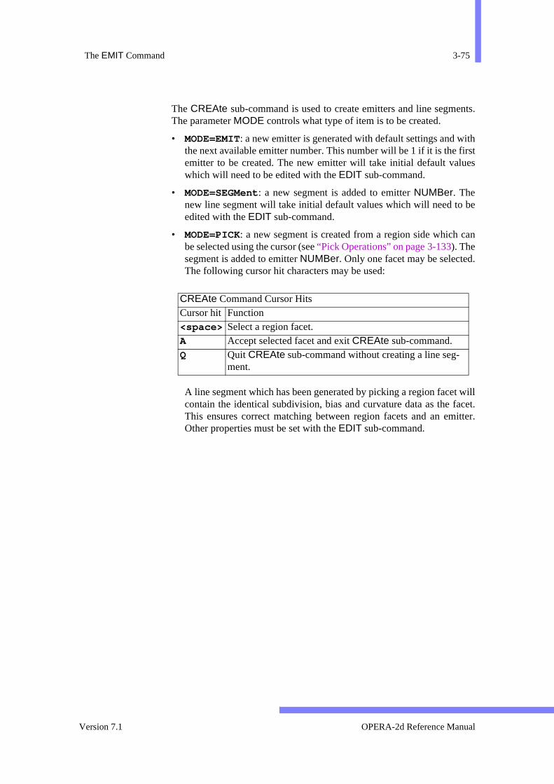
The EMIT Command 3-75
ents.
ithirstes
be
can
.
t willacet.itter.
The CREAte sub-command is used to create emitters and line segmThe parameter MODE controls what type of item is to be created.
• MODE=EMIT: a new emitter is generated with default settings and wthe next available emitter number. This number will be 1 if it is the femitter to be created. The new emitter will take initial default valuwhich will need to be edited with the EDIT sub-command.
• MODE=SEGMent: a new segment is added to emitter NUMBer. Thenew line segment will take initial default values which will need to edited with the EDIT sub-command.
• MODE=PICK: a new segment is created from a region side which be selected using the cursor (see “Pick Operations” on page 3-133). Thesegment is added to emitter NUMBer. Only one facet may be selectedThe following cursor hit characters may be used:
A line segment which has been generated by picking a region facecontain the identical subdivision, bias and curvature data as the fThis ensures correct matching between region facets and an emOther properties must be set with the EDIT sub-command.
CREAte Command Cursor HitsCursor hit Function <space> Select a region facet. A Accept selected facet and exit CREAte sub-command. Q Quit CREAte sub-command without creating a line seg-
ment.
Version 7.1 OPERA-2d Reference Manual
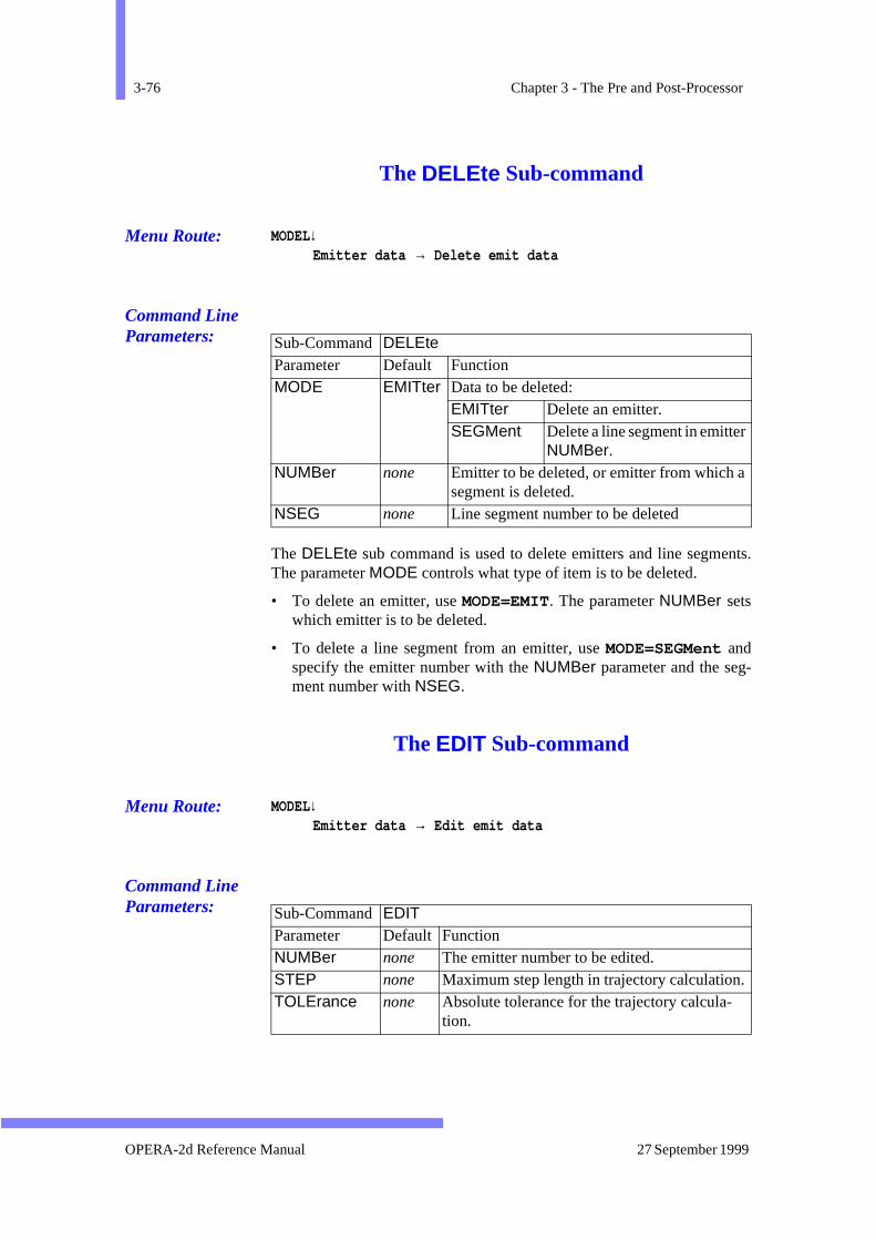
3-76 Chapter 3 - The Pre and Post-Processor
nts.
-
The DELEte Sub-command
Menu Route: MODEL↓Emitter data → Delete emit data
Command Line Parameters:
The DELEte sub command is used to delete emitters and line segmeThe parameter MODE controls what type of item is to be deleted.
• To delete an emitter, use MODE=EMIT. The parameter NUMBer setswhich emitter is to be deleted.
• To delete a line segment from an emitter, use MODE=SEGMent andspecify the emitter number with the NUMBer parameter and the segment number with NSEG.
The EDIT Sub-command
Menu Route: MODEL↓Emitter data → Edit emit data
Command Line Parameters:
Sub-Command DELEte Parameter Default Function MODE EMITter Data to be deleted:
EMITter Delete an emitter. SEGMent Delete a line segment in emitter
NUMBer. NUMBer none Emitter to be deleted, or emitter from which a
segment is deleted. NSEG none Line segment number to be deleted
Sub-Command EDIT Parameter Default Function NUMBer none The emitter number to be edited. STEP none Maximum step length in trajectory calculation.TOLErance none Absolute tolerance for the trajectory calcula-
tion.
OPERA-2d Reference Manual 27 September 1999
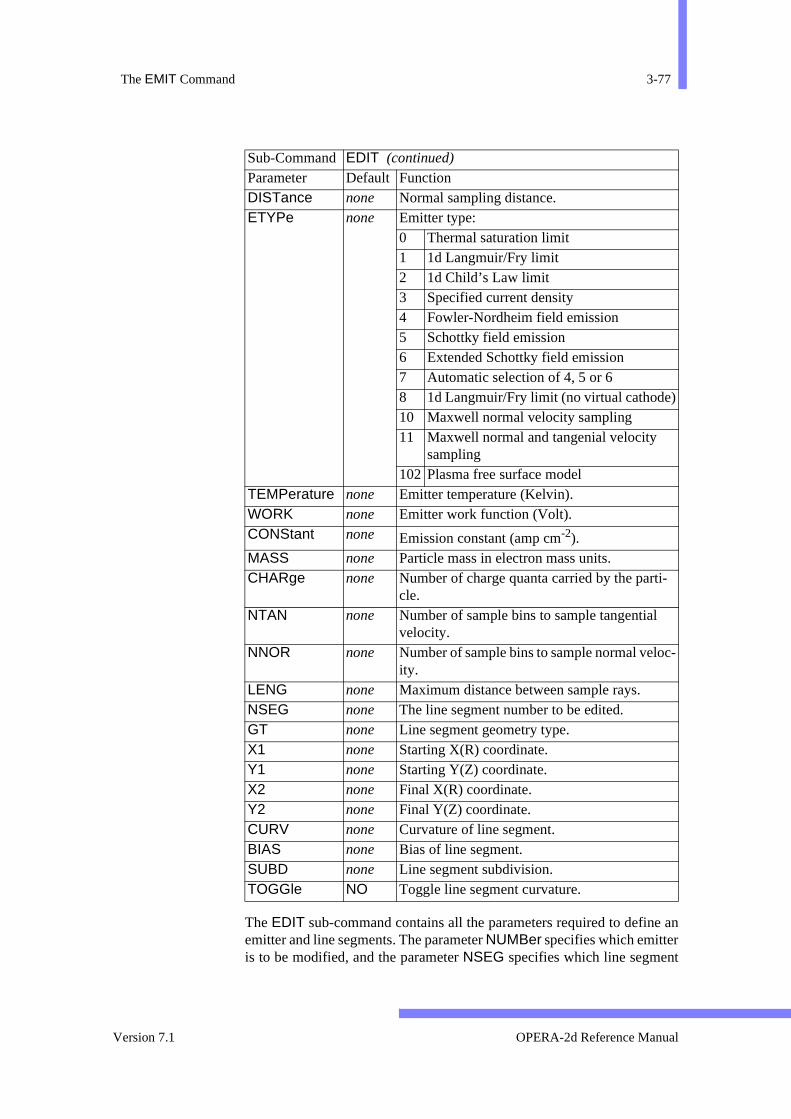
The EMIT Command 3-77
e an
t
c-
The EDIT sub-command contains all the parameters required to definemitter and line segments. The parameter NUMBer specifies which emitteris to be modified, and the parameter NSEG specifies which line segmen
DISTance none Normal sampling distance. ETYPe none Emitter type:
0 Thermal saturation limit1 1d Langmuir/Fry limit2 1d Child’s Law limit3 Specified current density4 Fowler-Nordheim field emission5 Schottky field emission6 Extended Schottky field emission7 Automatic selection of 4, 5 or 68 1d Langmuir/Fry limit (no virtual cathode)10 Maxwell normal velocity sampling11 Maxwell normal and tangenial velocity
sampling102 Plasma free surface model
TEMPerature none Emitter temperature (Kelvin). WORK none Emitter work function (Volt). CONStant none Emission constant (amp cm-2). MASS none Particle mass in electron mass units. CHARge none Number of charge quanta carried by the parti-
cle. NTAN none Number of sample bins to sample tangential
velocity. NNOR none Number of sample bins to sample normal velo
ity. LENG none Maximum distance between sample rays. NSEG none The line segment number to be edited. GT none Line segment geometry type. X1 none Starting X(R) coordinate. Y1 none Starting Y(Z) coordinate. X2 none Final X(R) coordinate. Y2 none Final Y(Z) coordinate. CURV none Curvature of line segment. BIAS none Bias of line segment. SUBD none Line segment subdivision. TOGGle NO Toggle line segment curvature.
Sub-Command EDIT (continued) Parameter Default Function
Version 7.1 OPERA-2d Reference Manual
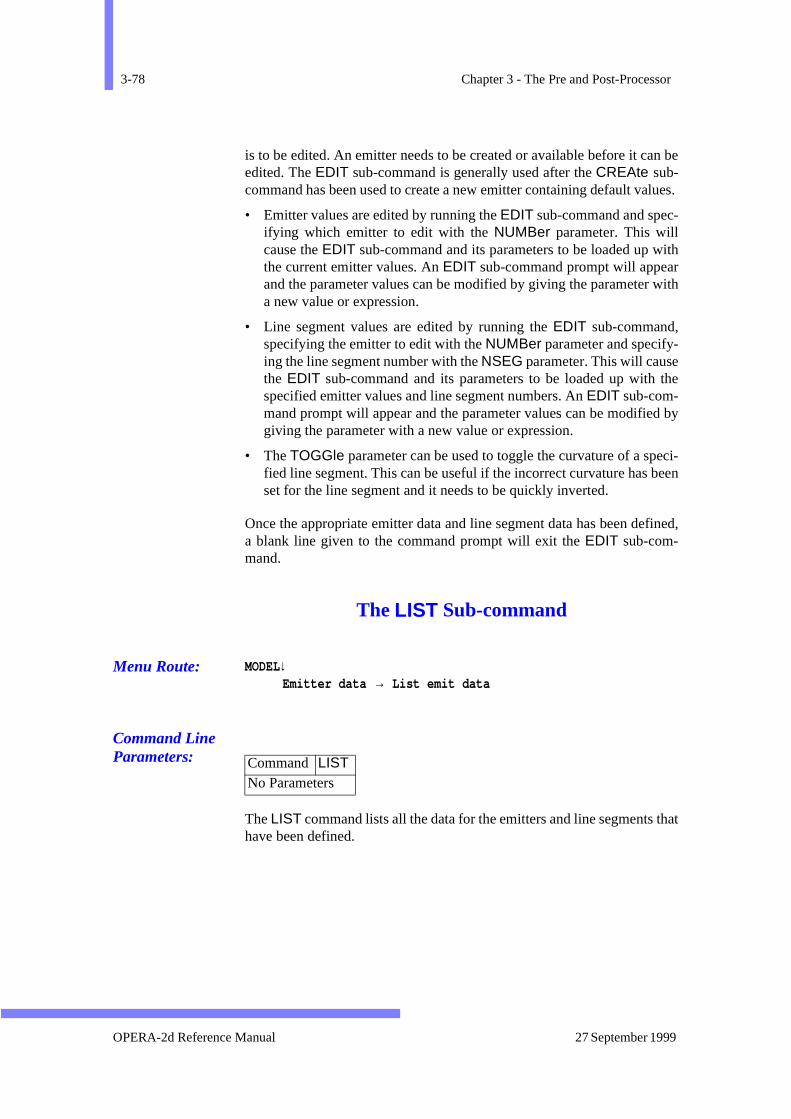
3-78 Chapter 3 - The Pre and Post-Processor
an be
lues.
-
ithr with
the
d by
eci-been
fined,
that
is to be edited. An emitter needs to be created or available before it cedited. The EDIT sub-command is generally used after the CREAte sub-command has been used to create a new emitter containing default va
• Emitter values are edited by running the EDIT sub-command and specifying which emitter to edit with the NUMBer parameter. This willcause the EDIT sub-command and its parameters to be loaded up wthe current emitter values. An EDIT sub-command prompt will appeaand the parameter values can be modified by giving the parametera new value or expression.
• Line segment values are edited by running the EDIT sub-command,specifying the emitter to edit with the NUMBer parameter and specify-ing the line segment number with the NSEG parameter. This will causethe EDIT sub-command and its parameters to be loaded up withspecified emitter values and line segment numbers. An EDIT sub-com-mand prompt will appear and the parameter values can be modifiegiving the parameter with a new value or expression.
• The TOGGle parameter can be used to toggle the curvature of a spfied line segment. This can be useful if the incorrect curvature has set for the line segment and it needs to be quickly inverted.
Once the appropriate emitter data and line segment data has been dea blank line given to the command prompt will exit the EDIT sub-com-mand.
The LIST Sub-command
Menu Route: MODEL↓Emitter data → List emit data
Command Line Parameters:
The LIST command lists all the data for the emitters and line segmentshave been defined.
Command LIST No Parameters
OPERA-2d Reference Manual 27 September 1999

The EMIT Command 3-79
it
sion
to or
e
d as
The QUIT Sub-command
Menu Route: MODEL↓Emit → Return
Command Line Parameters:
There are no parameters with the QUIT command. It allows the user to exthe EMIT sub-command and return to the top-level command input.
The READ Sub-command
Menu Route: MODEL↓Emitter data → Read an emit file
Command Line Parameters:
The READ sub-command reads in an emitter data file. The parameter FILEtakes the file name of the required emitter file. The four letter extenemit is added by default to the file name if no extension is specified.
The ADD parameter controls whether the file data is to be appended overwrite any existing data. Setting ADD=YES will append the file data andthe default setting (ADD=NO) will replace the existing emitter data with thnew data.
Once the data is read in, it will be available to be listed and modifierequired.
Command QUIT No Parameters
Sub-Command READ Parameter Default Function FILE none The file name of the emitter file to be read. ADD NO Add the file to the data already present.
Version 7.1 OPERA-2d Reference Manual
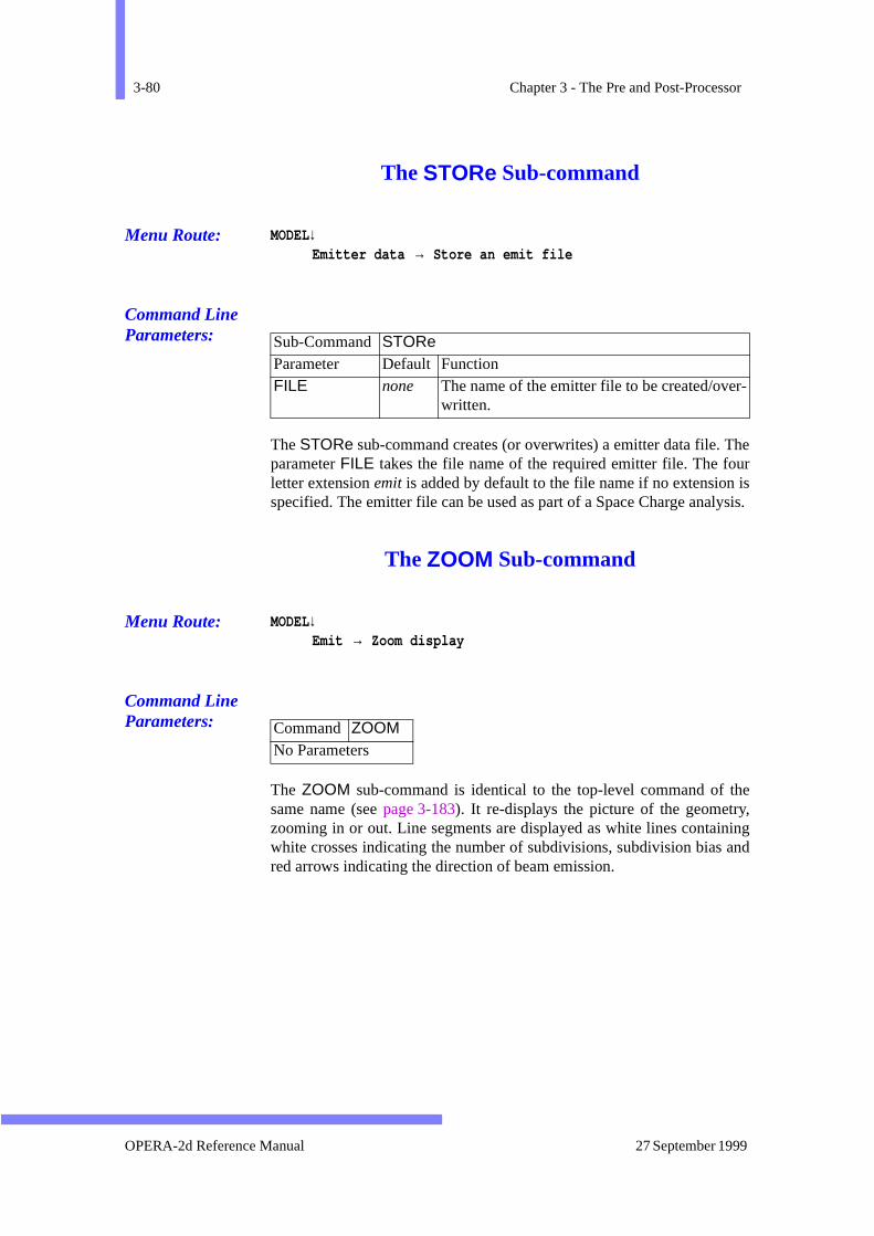
3-80 Chapter 3 - The Pre and Post-Processor
Theur islysis.
they,ning and
r-
The STORe Sub-command
Menu Route: MODEL↓Emitter data → Store an emit file
Command Line Parameters:
The STORe sub-command creates (or overwrites) a emitter data file. parameter FILE takes the file name of the required emitter file. The foletter extension emit is added by default to the file name if no extensionspecified. The emitter file can be used as part of a Space Charge ana
The ZOOM Sub-command
Menu Route: MODEL↓Emit → Zoom display
Command Line Parameters:
The ZOOM sub-command is identical to the top-level command of same name (see page 3-183). It re-displays the picture of the geometrzooming in or out. Line segments are displayed as white lines contaiwhite crosses indicating the number of subdivisions, subdivision biasred arrows indicating the direction of beam emission.
Sub-Command STORe Parameter Default Function FILE none The name of the emitter file to be created/ove
written.
Command ZOOM No Parameters
OPERA-2d Reference Manual 27 September 1999
The END Command 3-81
are
The END Command
Menu Route: FILE ↓End OPERA-2d/PP
Command Line Parameters:
The END command stops the Pre and Post-Processor. All data filesclosed.
Command ENDNo Parameters
Version 7.1 OPERA-2d Reference Manual
3-82 Chapter 3 - The Pre and Post-Processor
oup
be are
(ions
m-
The ERASe Command
Menu Route: MODEL↓Erase regions
Command Line Parameters:
The ERASe command erases the regions specified by number or grname using parameters REG1 and REG2 (see page 3-109). The remainingregions are renumbered to form a contiguous set starting at 1.
If neither REG1 nor REG2 are specified the regions to be erased canpicked from the display. In keyboard mode, the cursor commands<space> to select a region, H for help and Q to quit (see page 3-133).
The regions ERASed are selectively erased from the graphics window -ERASe) or the complete picture can be erased and the remaining regre-displayed (+ERASe).
Before each ERASe command, the current set of regions is saved in meory so that it can be restored using the UNDO command (page 3-172) ifregions are erased in error.
Command ERASe Parameter Default Function REG1 none Regions to be erased.
number Regions in range REG1 to REG2. group Regions in group named.
REG2 none Last region to be erased. * for highest region number. ERASe NO Clear graphics window and re-display switch:
NO Regions selectively erased from display. YES Graphics window cleared and picture re-
displayed.
OPERA-2d Reference Manual 27 September 1999
The EXTErnal Circuit Command 3-83
lysis
ge,ly), con-eter
nal-ase
of
e per
non-
The EXTErnal Circuit Command
Menu Route: MODEL↓Circuits
Command line Parameters:
External Circuits
External circuit configurations can be entered for Steady State ana(AC), Transient Analysis (TR) and for the Rotating Machine solver (RM).Circuit configurations are ignored in all other solvers.
External circuit data consists of power supply characteristics (voltaresistance and inductance), the length of the circuit (for XY models onand Opera conductors.The opera conductors are defined by having aductor number (also referred to as the circuit label or the region paramN). More than one region can have the same conductor number.
In AC analysis, the circuits are driven by the frequency defined in the aysis data (the SOLVe command), which is a cosine source, and a phwhich is defined in the circuit data. In TR and RM analysis all the drivedata is defined in the analysis data.
There are two types of external circuit, filamentary and eddy current cir-cuits and up to 100 circuits can be defined.
Filamentary circuits
• The conductors consist of many turns of stranded wire
• The current density is uniform over the conductor (the conductivitythe region must be zero), i.e. the skin effect is neglected.
• The properties are defined as the number of turns and the resistancunit length of the wire.
• The external impedance can be zero, if the conductor resistance inzero.
Eddy Current Circuits
• Conductors are ‘massive’ and each turn is modelled separately.
Commands EXTErnal CircuitNo Parameters
Version 7.1 OPERA-2d Reference Manual

3-84 Chapter 3 - The Pre and Post-Processor
the
duct- areen in
k
s
• Eddy currents can flow in the conductors.
• The property of the conductor is defined by the conductivity of region.
• The external resistance must be non zero.
Two external circuits can share common components (resistances, inances or OPERA conductor). Common resistances and inductancesentered with the EDIT sub-command once the circuits have beDEFIned. A conductor which exists in more than one circuit is definedeach circuit.
Full details of the way such data is used are given in the User Guide.
The following list of sub-commands are available:
DEFIne Sub-command
Command line Parameters:
EXTErnal Circuits Sub-commandsSub-command Function DEFIne Define circuit data page 3-84EDIT Edit circuit data page 3-86DELEte Delete circuit data page 3-87LIST List circuit data page 3-87LOAD Load circuit data page 3-87STORe Store circuit data page 3-88IMPOrt Import circuit data from a SPICE type file page 3-88CHECk Check circuit data agrees with the model data page 3-90QUIT Quit the EXTErnal Circuit command page 3-90
Sub-Command DEFIne Parameter Default FunctionSYMMetry 1 The number of similar conductors in series,
implied by boundary conditions. LENGth none Length of the circuit (XY-problems only). VOLTage none Sum of the voltage sources in the circuit (Pea
value for AC problems). PHASe 0 Phase of supply voltage (AC problems only). RESIstance 0 Resistance which is in series and is only in thi
circuit
OPERA-2d Reference Manual 27 September 1999
The EXTErnal Circuit Command 3-85
uitntered
(foreonsel,
s
.
The DEFI sub-command allows input in two stages. First the global circparameters are defined, where the power supply characteristics are eas VOLTage, PHASe, RESIstance and INDUctance. To calculate theinductance of the finite element model, the program also needs to knowXY problems only) the LENGth of the model. To correctly calculate thcurrent in models which have symmetry implied by boundary conditiSYMM is defined. If half the circuit is included in the finite element modSYMMetry=2, if a quarter, SYMMetry=4, etc., providing that the coils arewound in series.
Secondly the properties of each conductor are entered.
The program prompts for the conductor numbers (region parameter N) ofthe conductors which form the circuit along with:
• A function, whether to ADD a new conductor, BACKtrack to a previ-ous conductor or QUIT.
• the conductor number (circuit label, or region parameter N)
• the sense of a conductor, whether it is GO or RETUrn
• the number of turns (1 for an eddy current conductor)
• the resistance/unit length of the wire (filamentary circuits only).
Once defined, all the data can be modified using the EDIT command.
INDUctance 0 Inductance which is in series and is only in thicircuit
TYPE FILA Circuit type, EDDY Current or FILAmentary
FUNCtion none FUNCtion to take place on conductor data, ADD, BACKtrack (over write previous con-ductor) or QUIT
CONDuctor none Conductor NumberSENSe none Direction of the current in the conductor,
GO or RETUrnTURN none Number of turns (Filamentary circuits only
must be 1 for Eddy current circuits)UNIT none Resistance per unit length of the wire in ohms
(Filamentary circuits only)
Sub-Command DEFIne (continued)
Parameter Default Function
Version 7.1 OPERA-2d Reference Manual
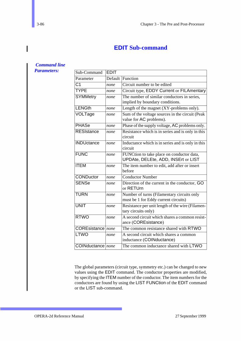
3-86 Chapter 3 - The Pre and Post-Processor
newd,
he
k
s
s
-
t-
EDIT Sub-command
Command line Parameters:
The global parameters (circuit type, symmetry etc.) can be changed tovalues using the EDIT command. The conductor properties are modifieby specifying the ITEM number of the conductor. The item numbers for tconductors are found by using the LIST FUNCtion of the EDIT commandor the LIST sub-command.
Sub-Command EDIT Parameter Default Function C1 none Circuit number to be editedTYPE none Circuit type, EDDY Current or FILAmentarySYMMetry none The number of similar conductors in series,
implied by boundary conditions. LENGth none Length of the magnet (XY-problems only). VOLTage none Sum of the voltage sources in the circuit (Pea
value for AC problems). PHASe none Phase of the supply voltage, AC problems only. RESIstance none Resistance which is in series and is only in thi
circuitINDUctance none Inductance which is in series and is only in thi
circuit FUNC none FUNCtion to take place on conductor data,
UPDAte, DELEte, ADD, INSErt or LISTITEM none The item number to edit, add after or insert
beforeCONDuctor none Conductor NumberSENSe none Direction of the current in the conductor, GO
or RETUrnTURN none Number of turns (Filamentary circuits only
must be 1 for Eddy current circuits)UNIT none Resistance per unit length of the wire (Filamen
tary circuits only)RTWO none A second circuit which shares a common resis
ance (COREsistance)COREsistance none The common resistance shared with RTWOLTWO none A second circuit which shares a common
inductance (COINductance)COINductance none The common inductance shared with LTWO
OPERA-2d Reference Manual 27 September 1999
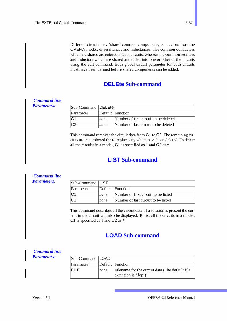
The EXTErnal Circuit Command 3-87
thectorsistors
rcuitsuits
delete
cur-el,
Different circuits may ‘share’ common components; conductors from OPERA model, or resistances and inductances. The common conduwhich are shared are entered in both circuits, whereas the common resand inductors which are shared are added into one or other of the ciusing the edit command. Both global circuit parameter for both circmust have been defined before shared components can be added.
DELEte Sub-command
Command line Parameters:
This command removes the circuit data from C1 to C2. The remaining cir-cuits are renumbered the to replace any which have been deleted. To all the circuits in a model, C1 is specified as 1 and C2 as *.
LIST Sub-command
Command line Parameters:
This command describes all the circuit data. If a solution is present therent in the circuit will also be displayed. To list all the circuits in a modC1 is specified as 1 and C2 as *.
LOAD Sub-command
Command line Parameters:
Sub-Command DELEte Parameter Default Function C1 none Number of first circuit to be deletedC2 none Number of last circuit to be deleted
Sub-Command LIST Parameter Default Function C1 none Number of first circuit to be listedC2 none Number of last circuit to be listed
Sub-Command LOAD Parameter Default Function FILE none Filename for the circuit data (The default file
extension is ‘.lop’)
Version 7.1 OPERA-2d Reference Manual
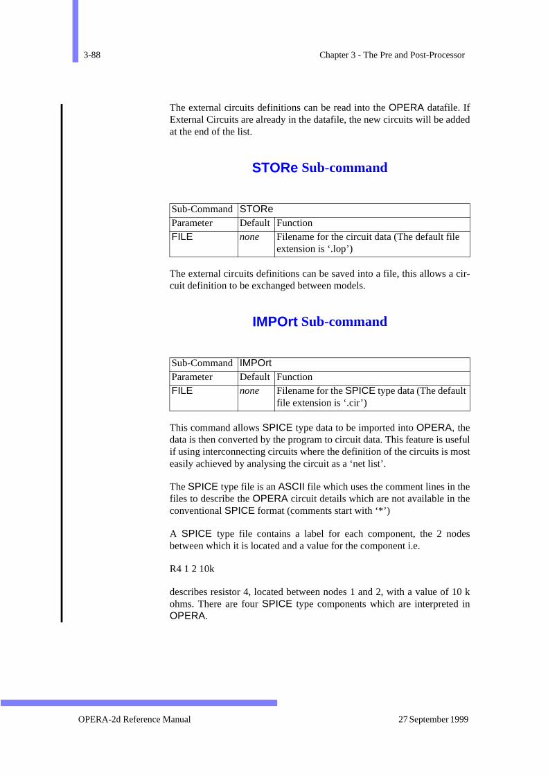
3-88 Chapter 3 - The Pre and Post-Processor
ded
cir-
sefulost
ee
des
10 kin
The external circuits definitions can be read into the OPERA datafile. IfExternal Circuits are already in the datafile, the new circuits will be adat the end of the list.
STORe Sub-command
The external circuits definitions can be saved into a file, this allows acuit definition to be exchanged between models.
IMPOrt Sub-command
This command allows SPICE type data to be imported into OPERA, thedata is then converted by the program to circuit data. This feature is uif using interconnecting circuits where the definition of the circuits is measily achieved by analysing the circuit as a ‘net list’.
The SPICE type file is an ASCII file which uses the comment lines in thfiles to describe the OPERA circuit details which are not available in thconventional SPICE format (comments start with ‘*’)
A SPICE type file contains a label for each component, the 2 nobetween which it is located and a value for the component i.e.
R4 1 2 10k
describes resistor 4, located between nodes 1 and 2, with a value ofohms. There are four SPICE type components which are interpreted OPERA.
Sub-Command STORe Parameter Default Function FILE none Filename for the circuit data (The default file
extension is ‘.lop’)
Sub-Command IMPOrt Parameter Default Function FILE none Filename for the SPICE type data (The default
file extension is ‘.cir’)
OPERA-2d Reference Manual 27 September 1999

The EXTErnal Circuit Command 3-89
st be
ish
e
ned
ir-
r
Only one comment can be placed on any one line. The comments muplaced in the file before the lines which they affect.
The first line in the file is the title (and is ignored) and the file must finwith a the line
.end
A SPICE type file can only contain FILAmentary or Eddy current circuitsand the LENGth and SYMMetry must be the same through out the file.Onconductor in each circuit must have its SENSe defined as either GO orRETURN.
In a SPICE type file, the component values use the code letters defibelow to describe the exponent of the values.
SPICE type component
Description Meaning of ‘value’
O OPERA conductor Conductor number (other propertiesare taken from the comment lines *TURNs and *RESIst)
Vin Voltage Source Voltage (volts)R Resistor Resistance (ohms)L Inductor Inductance (Henries)
Comment Default Description*TYPE FILA Circuit type, EDDY of FILAmentary*SYMMetry 1 Symmetry of the circuits*LENGth none Length of the Circuits*PHASe 0 Phase of the all Voltage sources*SENSe none Defines the sense of one conductor in a c
cuit*TURNs 1 Turns per conductor (set to 1 for EDDY)*RESIst 0 Resistance per unit length for the conducto
(set to 0 for EDDY)
Exponent Symbol Value DescriptionF 1e-15 femtoP 1e-12 picoN 1e-9 nanoU 1e-6 microM 1e-3 milli
Version 7.1 OPERA-2d Reference Manual
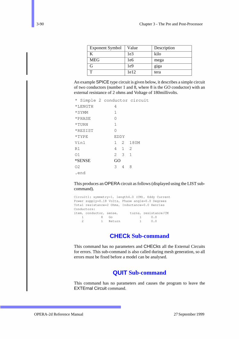
3-90 Chapter 3 - The Pre and Post-Processor
ith an
-
o all
ve the
An example SPICE type circuit is given below, it describes a simple circuof two conductors (number 1 and 8, where 8 is the GO conductor) witexternal resistance of 2 ohms and Voltage of 180millivolts.
This produces an OPERA circuit as follows (displayed using the LIST subcommand).
Circuit1: symmetry=1, length4.0 (CM), Eddy CurrentPower supply=0.18 Volts, Phase angle=0.0 DegreesTotal resistance=2 Ohms, Inductance=0.0 HenriesConductors:item, conductor, sense, turns, resistance/CM 1 8 Go 1 0.0 2 1 Return 1 0.0
CHECk Sub-command
This command has no parameters and CHECks all the External Circuitsfor errors. This sub-command is also called during mesh generation, serrors must be fixed before a model can be analysed.
QUIT Sub-command
This command has no parameters and causes the program to leaEXTErnal Circuit command.
K 1e3 kiloMEG 1e6 megaG 1e9 gigaT 1e12 tera
* Simple 2 conductor circuit
*LENGTH 4
*SYMM 1
*PHASE 0
*TURN 1
*RESIST 0
*TYPE EDDY
Vin1 1 2 180M
R1 4 1 2
O1 2 3 1
*SENSE GOO2 3 4 8
.end
Exponent Symbol Value Description
OPERA-2d Reference Manual 27 September 1999
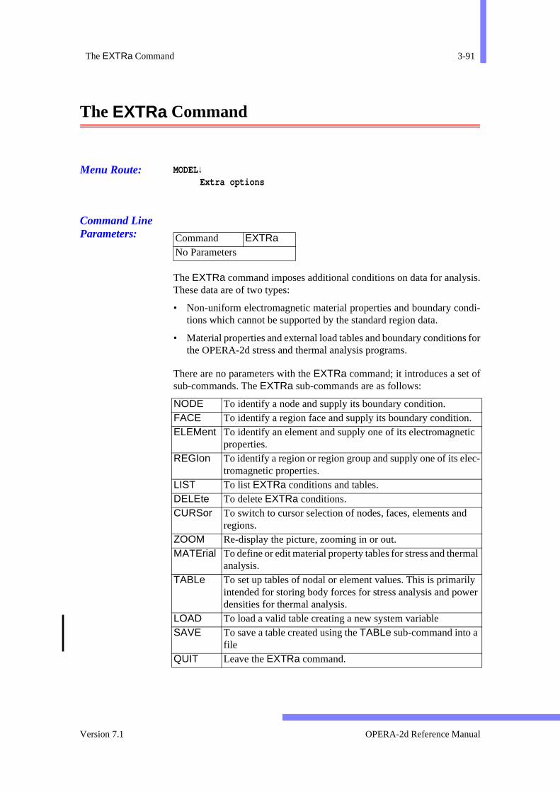
The EXTRa Command 3-91
sis.
ndi-
s for
f
. ic
ec-
d
al
ily er
The EXTRa Command
Menu Route: MODEL↓Extra options
Command Line Parameters:
The EXTRa command imposes additional conditions on data for analyThese data are of two types:
• Non-uniform electromagnetic material properties and boundary cotions which cannot be supported by the standard region data.
• Material properties and external load tables and boundary conditionthe OPERA-2d stress and thermal analysis programs.
There are no parameters with the EXTRa command; it introduces a set osub-commands. The EXTRa sub-commands are as follows:
Command EXTRaNo Parameters
NODE To identify a node and supply its boundary condition. FACE To identify a region face and supply its boundary conditionELEMent To identify an element and supply one of its electromagnet
properties. REGIon To identify a region or region group and supply one of its el
tromagnetic properties. LIST To list EXTRa conditions and tables. DELEte To delete EXTRa conditions. CURSor To switch to cursor selection of nodes, faces, elements an
regions. ZOOM Re-display the picture, zooming in or out. MATErial To define or edit material property tables for stress and therm
analysis. TABLe To set up tables of nodal or element values. This is primar
intended for storing body forces for stress analysis and powdensities for thermal analysis.
LOAD To load a valid table creating a new system variableSAVE To save a table created using the TABLe sub-command into a
fileQUIT Leave the EXTRa command.
Version 7.1 OPERA-2d Reference Manual
3-92 Chapter 3 - The Pre and Post-Processor
s.
ndi-
rmal of a
t or
terms
s ofhese
ionsritesn the
Inbers
datar. Theorce pro-itionalystemnd. If thenin and
into
Boundary Conditions and Electromagnetic Material Properties
EXTRa conditions can be applied to nodes, faces, elements or region
On nodes, either individually or all nodes on a face, the boundary cotions V (fixed potential) or DV (fixed normal derivative of potential) canbe set. In addition, boundary conditions for stress analysis and theanalysis can be given. For stress analysis, this allows the impositionSKEW angle, a LOAD or a CONStraint. For thermal analysis, this allowsthe imposition of constant TEMPeratures or THERmal cooling condi-tions.
For elements, either individually or all elements of a region, currencharge DENSity, PERMeability or PERMittivity, PHASe angle and con-ductivity (SIGMa) can be set.
In each case, nodes or elements, the values given can be expressed inof the coordinates (system variables X, Y or R, Z). Such expressions areevaluated for each node or element centroid, allowing spatial variationproperties. The only other system variable which can be used in texpressions is PI.
N.B. User variables should not be used in EXTRa expressions.
The EXTRa sub-commands should be used to define the extra conditafter the MESH has been generated successfully. The command overwthe appropriate node and element values in the mesh. If for any reasoMESH command has to be used after EXTRa conditions have beenimposed, the EXTRa data is not lost, but is re-imposed automatically. this case EXTRa data should be checked, since node and element nummight be changed by re-meshing.
Tables
Tables are the means of transferring extra nodal or element basedbetween OPERA-2d analysis programs and the pre and post-processotables are primarily intended for storing the element values of Lorentz fdensity or power density as input to the stress and thermal analysisgrams. Tables can also be used while post-processing to create addsystem variables from the values of expressions at every node. The svariables thus created can be used in any post-processing commanames are given for system variables to hold the spatial derivativesthese can also be used in post-processing. Tables can be stored loaded from files using the SAVE and LOAD sub-commands (page 3-97and page 3-102) so that values created by one analysis can be loaded
OPERA-2d Reference Manual 27 September 1999
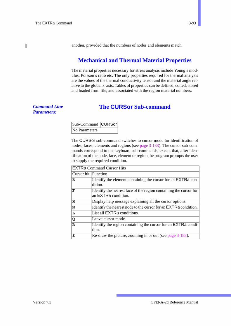
The EXTRa Command 3-93
mod-lysise rel-tored.
of
iden- user
for
another, provided that the numbers of nodes and elements match.
Mechanical and Thermal Material Properties
The material properties necessary for stress analysis include Young’s ulus, Poisson’s ratio etc. The only properties required for thermal anaare the values of the thermal conductivity tensor and the material anglative to the global x-axis. Tables of properties can be defined, edited, sand loaded from file, and associated with the region material numbers
Command Line Parameters:
The CURSor Sub-command
The CURSor sub-command switches to cursor mode for identificationnodes, faces, elements and regions (see page 3-133). The cursor sub-com-mands correspond to the keyboard sub-commands, except that, aftertification of the node, face, element or region the program prompts theto supply the required condition.
Sub-Command CURSorNo Parameters
EXTRa Command Cursor Hits Cursor hit Function E Identify the element containing the cursor for an EXTRa con-
dition. F Identify the nearest face of the region containing the cursor
an EXTRa condition. H Display help message explaining all the cursor options. N Identify the nearest node to the cursor for an EXTRa condition. L List all EXTRa conditions. Q Leave cursor mode. R Identify the region containing the cursor for an EXTRa condi-
tion. Z Re-draw the picture, zooming in or out (see page 3-183).
Version 7.1 OPERA-2d Reference Manual

3-94 Chapter 3 - The Pre and Post-Processor
to
The DELEte Sub-command
Menu Routes: MODEL↓Extra options → Extra conditions → Delete conditions
Command Line Parameters:
The DELEte command removes some or all of the EXTRa conditionsspecified by TYPE, C1 and C2. The remaining data are renumbered form a contiguous set starting at 1.
The ELEMent Sub-command
Menu Route: MODEL↓Extra options → Extra
conditions → Electromagneticmaterials → Pick an element
Command Line Parameters:
Sub-Command DELEte Parameter Default Function TYPE CONDition Type of EXTRa data:
COND EXTRa conditions. C1 none First data item to be deleted. C2 none Last data item to be deleted. *for highest
number.
Sub-Command ELEMent Parameter Default Function XE none X-coordinate of a point inside the element. YE none Y-coordinate of a point inside the element. CONDition PHASe Name of the material property to be set.
DENSity Current or charge density. PERM Permeability or permittivity. PHAS Angle in degrees. SIGM Conductivity, or packing factor.
FUNCtion 0 Function or value for property.
OPERA-2d Reference Manual 27 September 1999
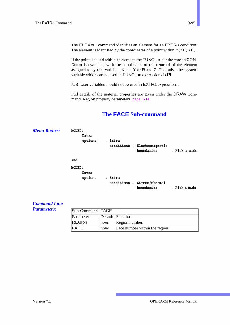
The EXTRa Command 3-95
ent
The ELEMent command identifies an element for an EXTRa condition.The element is identified by the coordinates of a point within it (XE, YE).
If the point is found within an element, the FUNCtion for the chosen CON-Dition is evaluated with the coordinates of the centroid of the elemassigned to system variables X and Y or R and Z. The only other systemvariable which can be used in FUNCtion expressions is PI.
N.B. User variables should not be used in EXTRa expressions.
Full details of the material properties are given under the DRAW Com-mand, Region property parameters, page 3-44.
The FACE Sub-command
Menu Routes: MODEL↓Extraoptions → Extra
conditions → Electromagneticboundaries → Pick a side
and
MODEL↓Extraoptions → Extra
conditions → Stress/thermalboundaries → Pick a side
Command Line Parameters:
Sub-Command FACE Parameter Default Function REGIon none Region number. FACE none Face number within the region.
Version 7.1 OPERA-2d Reference Manual
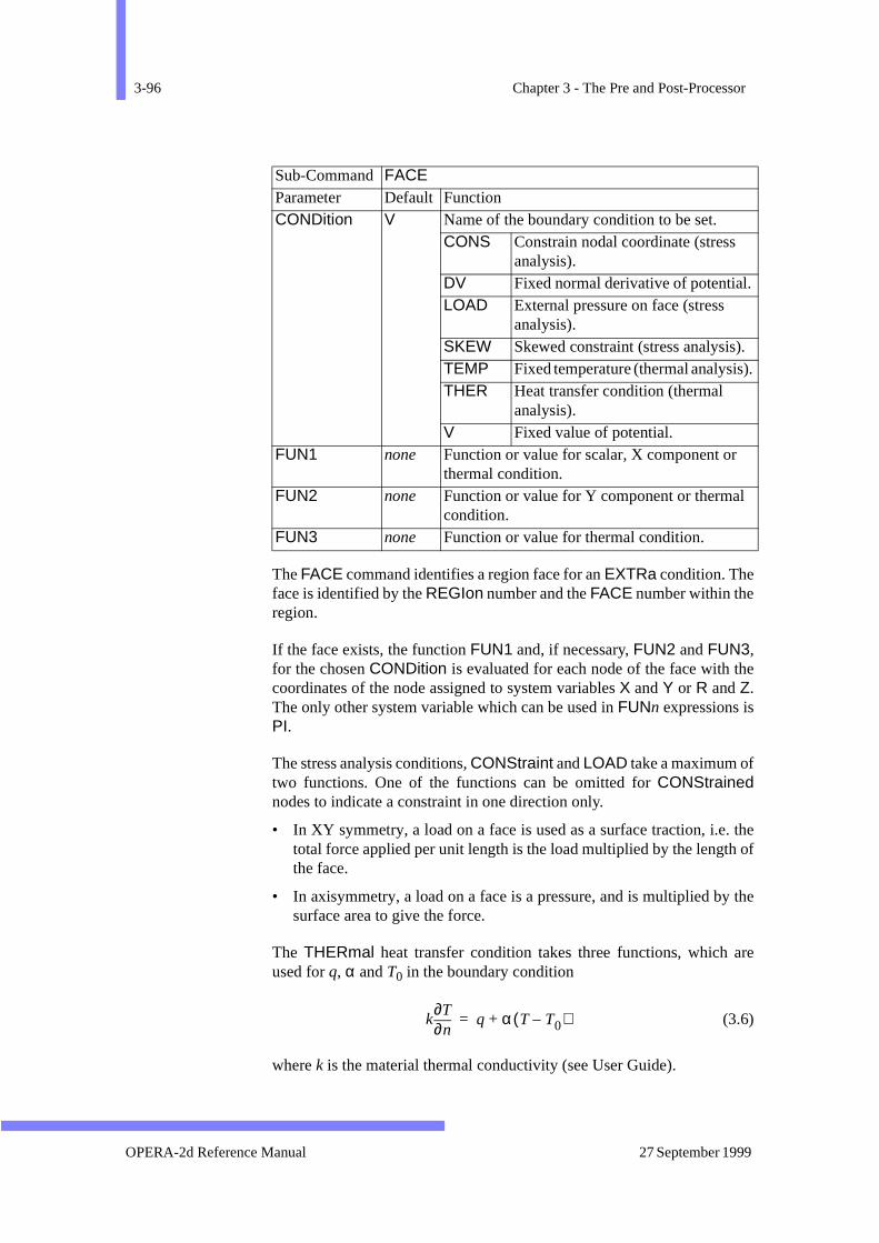
3-96 Chapter 3 - The Pre and Post-Processor
he
. the of
the
are
. ).
The FACE command identifies a region face for an EXTRa condition. Theface is identified by the REGIon number and the FACE number within theregion.
If the face exists, the function FUN1 and, if necessary, FUN2 and FUN3,for the chosen CONDition is evaluated for each node of the face with tcoordinates of the node assigned to system variables X and Y or R and Z.The only other system variable which can be used in FUNn expressions isPI.
The stress analysis conditions, CONStraint and LOAD take a maximum oftwo functions. One of the functions can be omitted for CONStrainednodes to indicate a constraint in one direction only.
• In XY symmetry, a load on a face is used as a surface traction, i.etotal force applied per unit length is the load multiplied by the lengththe face.
• In axisymmetry, a load on a face is a pressure, and is multiplied bysurface area to give the force.
The THERmal heat transfer condition takes three functions, which used for q, α and T0 in the boundary condition
(3.6)
where k is the material thermal conductivity (see User Guide).
CONDition V Name of the boundary condition to be set. CONS Constrain nodal coordinate (stress
analysis). DV Fixed normal derivative of potential.LOAD External pressure on face (stress
analysis). SKEW Skewed constraint (stress analysis)TEMP Fixed temperature (thermal analysisTHER Heat transfer condition (thermal
analysis). V Fixed value of potential.
FUN1 none Function or value for scalar, X component or thermal condition.
FUN2 none Function or value for Y component or thermalcondition.
FUN3 none Function or value for thermal condition.
Sub-Command FACE Parameter Default Function
kn∂
∂Tq α T T0–( )+=
OPERA-2d Reference Manual 27 September 1999

The EXTRa Command 3-97
re-be dis-
N.B. User variables should not be used in EXTRa expressions.
The LIST Sub-command
Menu Routes: MODEL↓Extra options → Extra conditions → List conditions
and
MODEL↓Extra options → Solution tables → List tables
Command Line Parameters:
The LIST sub-command prints all existing EXTRa conditions or tables tothe screen.
The LOAD Sub-command
Menu Routes: MODEL↓Extra options → Solution tables → Load a table
Command Line Parameters:
The LOAD sub-command loads a file containing a valid table into the Pand Post-Processor. Once loaded the data contained in the table may played using the system variable associated with the table.
Sub-Command LIST Parameter Default Function TYPE CONDitions Type of EXTRa data:
COND EXTRa conditions. TABL Tables.
Sub-Command LOAD Parameter Default Function FILE none Name of the table file
Version 7.1 OPERA-2d Reference Manual
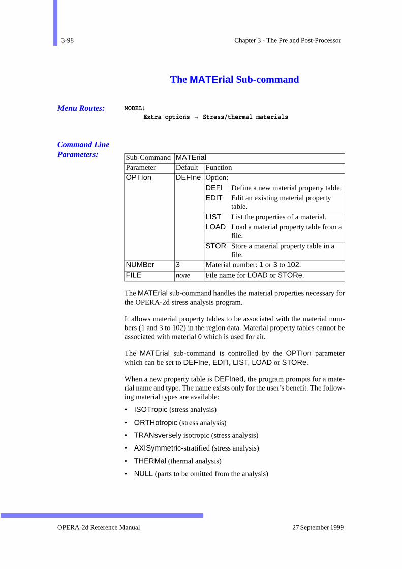
3-98 Chapter 3 - The Pre and Post-Processor
y for
um-ot be
-low-
The MATErial Sub-command
Menu Routes: MODEL↓Extra options → Stress/thermal materials
Command Line Parameters:
The MATErial sub-command handles the material properties necessarthe OPERA-2d stress analysis program.
It allows material property tables to be associated with the material nbers (1 and 3 to 102) in the region data. Material property tables cannassociated with material 0 which is used for air.
The MATErial sub-command is controlled by the OPTIon parameterwhich can be set to DEFIne, EDIT, LIST, LOAD or STORe.
When a new property table is DEFIned, the program prompts for a material name and type. The name exists only for the user’s benefit. The foling material types are available:
• ISOTropic (stress analysis)
• ORTHotropic (stress analysis)
• TRANsversely isotropic (stress analysis)
• AXISymmetric-stratified (stress analysis)
• THERMal (thermal analysis)
• NULL (parts to be omitted from the analysis)
Sub-Command MATErial Parameter Default Function OPTIon DEFIne Option:
DEFI Define a new material property table.EDIT Edit an existing material property
table. LIST List the properties of a material. LOAD Load a material property table from a
file. STOR Store a material property table in a
file. NUMBer 3 Material number: 1 or 3 to 102. FILE none File name for LOAD or STORe.
OPERA-2d Reference Manual 27 September 1999

The EXTRa Command 3-99
to
uired
tond or
d for
edrred
When DEFIning or EDITing another set of sub-commands can be usedgive values to the required properties. These are:
In the case of some of the properties, the number of values reqdepends on the type of material being defined. The keywords CLEAr,HELP, LIST, QUIT and TYPE can be used while defining properties remove all properties, request help, list properties, leave the commachange the material type.
• Example: OPERA-2d > extra
Supply extra conditions on analysis
OP2-EXTRA > mate defi 3
Define/Edit material property tables (Stress Analysis) Give material name and type.Types are (ISOTropic, ORTHotropic, TRANsversely isotropic, AXISymmetric-stratified or NULL)
OP2-MATE > steel iso
Give property name and values, or type HELP, LISTor QUIT
OP2-MATE > pois help
Poisson’s Ratio: Nu
OP2-MATE > pois 1.e10
...
The User Guide gives information on which properties must be supplieeach type of material.
The LOAD and STORe options allow material property tables to be storin files independent of other OPERA-2d data. They can thus be transfe
Stress Analysis Material PropertiesANGLe The angle between principal and global axes.CSTRess The maximum allowable compressive stress.DENSity The mass density.POISson The Poisson’s ratio.SHEAr The shear modulus.STSRess The maximum allowable shear stress.THERmal The thermal expansion integrals.TSTRess The maximum allowable tensile stress.YOUNg The Young’s modulus.
Thermal Analysis Material PropertiesANGLe The angle between principal and global axes.DENSity The mass density.SPECific The specific heat capacity.THERmal The thermal conductivity tensor.
Version 7.1 OPERA-2d Reference Manual
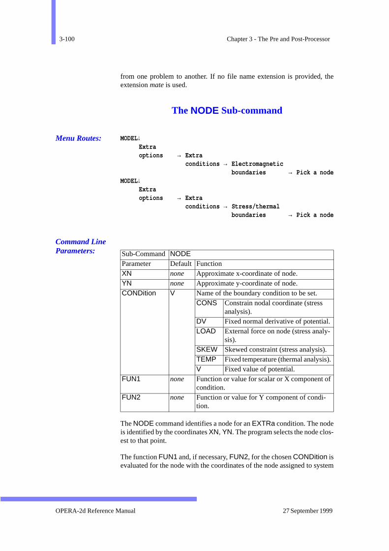
3-100 Chapter 3 - The Pre and Post-Processor
the
s-
stem
-
.
f
from one problem to another. If no file name extension is provided,extension mate is used.
The NODE Sub-command
Menu Routes: MODEL↓Extraoptions → Extra
conditions → Electromagneticboundaries → Pick a node
MODEL↓Extraoptions → Extra
conditions → Stress/thermalboundaries → Pick a node
Command Line Parameters:
The NODE command identifies a node for an EXTRa condition. The nodeis identified by the coordinates XN, YN. The program selects the node cloest to that point.
The function FUN1 and, if necessary, FUN2, for the chosen CONDition isevaluated for the node with the coordinates of the node assigned to sy
Sub-Command NODE Parameter Default Function XN none Approximate x-coordinate of node. YN none Approximate y-coordinate of node. CONDition V Name of the boundary condition to be set.
CONS Constrain nodal coordinate (stress analysis).
DV Fixed normal derivative of potential. LOAD External force on node (stress analy
sis). SKEW Skewed constraint (stress analysis). TEMP Fixed temperature (thermal analysis)V Fixed value of potential.
FUN1 none Function or value for scalar or X component ocondition.
FUN2 none Function or value for Y component of condi-tion.
OPERA-2d Reference Manual 27 September 1999

The EXTRa Command 3-101
e
h.
variables X and Y or R and Z. The only other system variable which can bused in FUNn expressions is PI.
The stress analysis conditions, CONStraint and LOAD take a maximum oftwo functions. One of the functions can be omitted for CONStrainednodes to indicate a constraint in one direction only.
• In XY symmetry, a load on a node is used as a force per unit lengt
• In axisymmetry, a load on a node is multiplied by 2πr to give the force.
N.B. User variables should not be used in EXTRa expressions.
The QUIT Sub-command
Command Line Parameters:
The QUIT sub-command terminates the EXTRa command and returns totop-level command input.
The REGIon Sub-command
Menu Route: MODEL↓Extraoptions → Extra
conditions → Electromagneticmaterial s → Pick a region
→ Region group
Command Line Parameters:
Sub-Command QUITNo Parameters
Sub-Command REGIon Parameter Default Function REGIon none Region number or group name.
Version 7.1 OPERA-2d Reference Manual
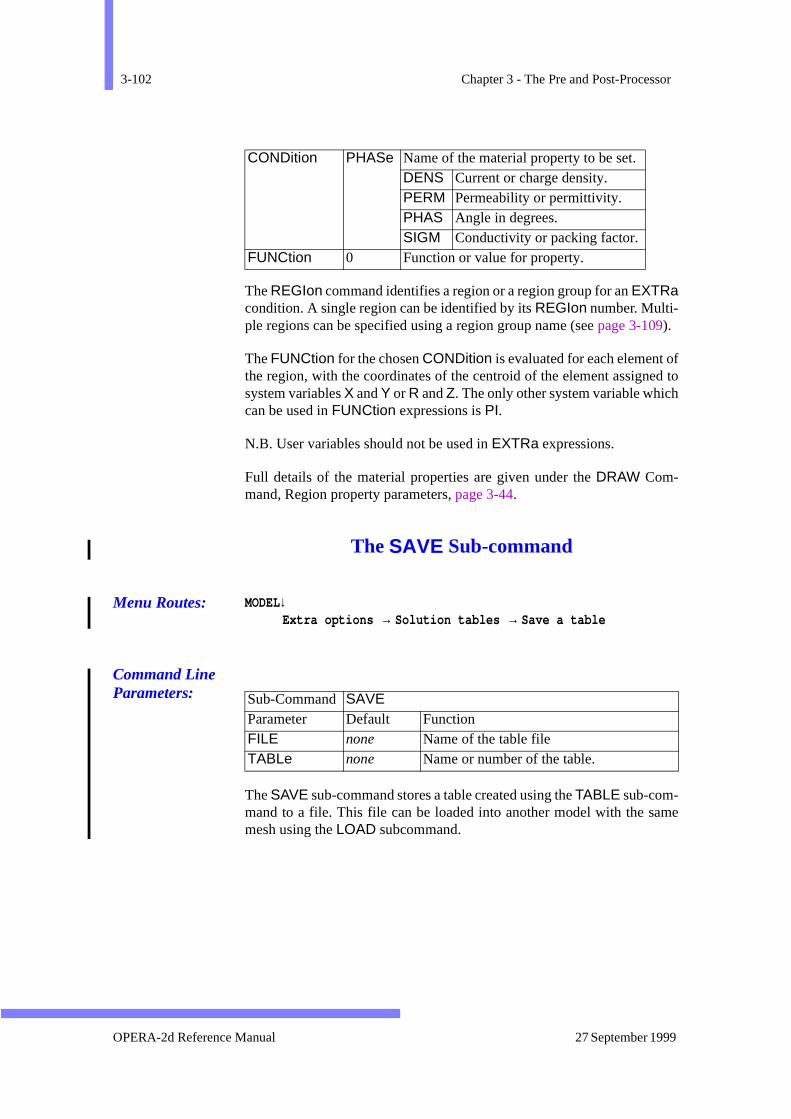
3-102 Chapter 3 - The Pre and Post-Processor
fed toh
ame
The REGIon command identifies a region or a region group for an EXTRacondition. A single region can be identified by its REGIon number. Multi-ple regions can be specified using a region group name (see page 3-109).
The FUNCtion for the chosen CONDition is evaluated for each element othe region, with the coordinates of the centroid of the element assignsystem variables X and Y or R and Z. The only other system variable whiccan be used in FUNCtion expressions is PI.
N.B. User variables should not be used in EXTRa expressions.
Full details of the material properties are given under the DRAW Com-mand, Region property parameters, page 3-44.
The SAVE Sub-command
Menu Routes: MODEL↓Extra options → Solution tables → Save a table
Command Line Parameters:
The SAVE sub-command stores a table created using the TABLE sub-com-mand to a file. This file can be loaded into another model with the smesh using the LOAD subcommand.
CONDition PHASe Name of the material property to be set. DENS Current or charge density. PERM Permeability or permittivity. PHAS Angle in degrees. SIGM Conductivity or packing factor.
FUNCtion 0 Function or value for property.
Sub-Command SAVE Parameter Default Function FILE none Name of the table fileTABLe none Name or number of the table.
OPERA-2d Reference Manual 27 September 1999
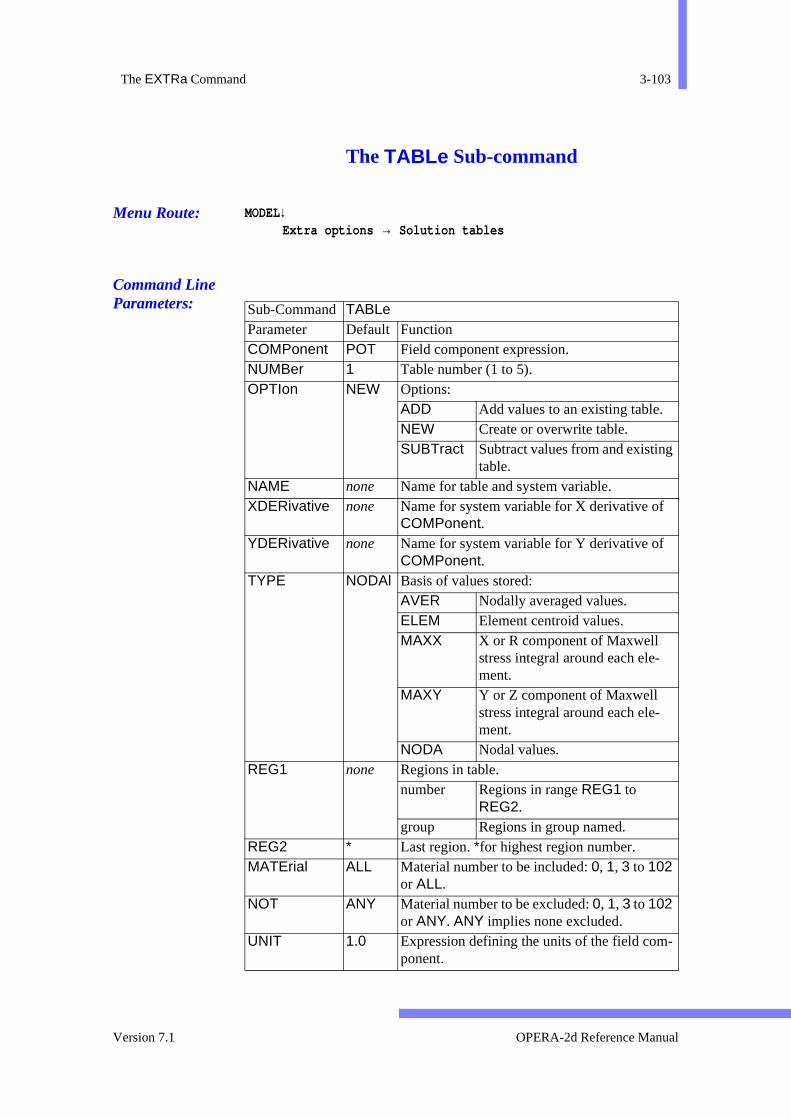
The EXTRa Command 3-103
The TABLe Sub-command
Menu Route: MODEL↓Extra options → Solution tables
Command Line Parameters:
Sub-Command TABLe Parameter Default Function COMPonent POT Field component expression. NUMBer 1 Table number (1 to 5). OPTIon NEW Options:
ADD Add values to an existing table. NEW Create or overwrite table. SUBTract Subtract values from and existing
table. NAME none Name for table and system variable. XDERivative none Name for system variable for X derivative of
COMPonent. YDERivative none Name for system variable for Y derivative of
COMPonent. TYPE NODAl Basis of values stored:
AVER Nodally averaged values. ELEM Element centroid values. MAXX X or R component of Maxwell
stress integral around each ele-ment.
MAXY Y or Z component of Maxwell stress integral around each ele-ment.
NODA Nodal values. REG1 none Regions in table.
number Regions in range REG1 to REG2.
group Regions in group named. REG2 * Last region. *for highest region number. MATErial ALL Material number to be included: 0, 1, 3 to 102
or ALL. NOT ANY Material number to be excluded: 0, 1, 3 to 102
or ANY. ANY implies none excluded. UNIT 1.0 Expression defining the units of the field com-
ponent.
Version 7.1 OPERA-2d Reference Manual
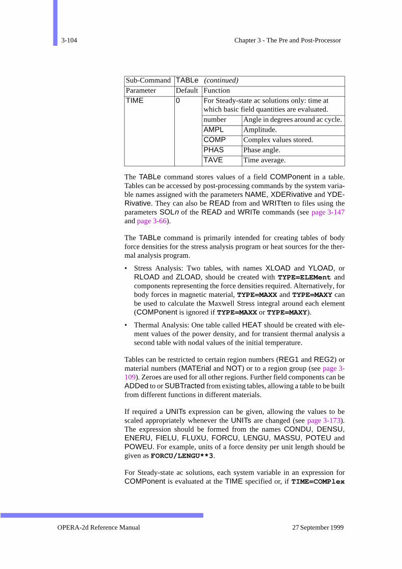
3-104 Chapter 3 - The Pre and Post-Processor
varia-
dy ther-
, for
ment
-sis a
n beilt
be
be
n for
.
The TABLe command stores values of a field COMPonent in a table.Tables can be accessed by post-processing commands by the systemble names assigned with the parameters NAME, XDERivative and YDE-Rivative. They can also be READ from and WRITten to files using theparameters SOLn of the READ and WRITe commands (see page 3-147and page 3-66).
The TABLe command is primarily intended for creating tables of boforce densities for the stress analysis program or heat sources for themal analysis program.
• Stress Analysis: Two tables, with names XLOAD and YLOAD, orRLOAD and ZLOAD, should be created with TYPE=ELEMent andcomponents representing the force densities required. Alternativelybody forces in magnetic material, TYPE=MAXX and TYPE=MAXY canbe used to calculate the Maxwell Stress integral around each ele(COMPonent is ignored if TYPE=MAXX or TYPE=MAXY).
• Thermal Analysis: One table called HEAT should be created with element values of the power density, and for transient thermal analysecond table with nodal values of the initial temperature.
Tables can be restricted to certain region numbers (REG1 and REG2) ormaterial numbers (MATErial and NOT) or to a region group (see page 3-109). Zeroes are used for all other regions. Further field components caADDed to or SUBTracted from existing tables, allowing a table to be bufrom different functions in different materials.
If required a UNITs expression can be given, allowing the values to scaled appropriately whenever the UNITs are changed (see page 3-173).The expression should be formed from the names CONDU, DENSU,ENERU, FIELU, FLUXU, FORCU, LENGU, MASSU, POTEU andPOWEU. For example, units of a force density per unit length shouldgiven as FORCU/LENGU**3.
For Steady-state ac solutions, each system variable in an expressioCOMPonent is evaluated at the TIME specified or, if TIME=COMPlex
TIME 0 For Steady-state ac solutions only: time at which basic field quantities are evaluated. number Angle in degrees around ac cycleAMPL Amplitude. COMP Complex values stored. PHAS Phase angle. TAVE Time average.
Sub-Command TABLe (continued)
Parameter Default Function
OPERA-2d Reference Manual 27 September 1999
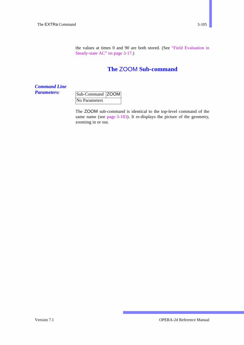
The EXTRa Command 3-105
they,
the values at times 0 and 90 are both stored. (See “Field Evaluation inSteady-state AC” on page 3-17.)
The ZOOM Sub-command
Command Line Parameters:
The ZOOM sub-command is identical to the top-level command of same name (see page 3-183). It re-displays the picture of the geometrzooming in or out.
Sub-Command ZOOMNo Parameters
Version 7.1 OPERA-2d Reference Manual

3-106 Chapter 3 - The Pre and Post-Processor
The GRAPh Command
Menu Route: FILE ↓Graph data in text file
Command Line Parameters: Command GRAPh
Parameter Default Function FILE none File name XVALue COL1 Expression for x-axis values. XLABel X Label for x-axis. XMINimum * X-axis minimum value. Use * for automatic scal-
ing. XMAXimum * X-axis maximum value. Use * for automatic scal-
ing. YVALue COL1 Expression for y-axis values. YLABel Y Label for y-axis. YMINimum * Y-axis minimum value. Use * for automatic scal-
ing. YMAXimum * Y-axis maximum value. Use * for automatic scal-
ing. TITLe none Additional title for line. STYLe 1 Line style:
0 Solid line. >0 Broken line.
COLOur 1 Line colour SYMBol 0 Symbols at data points:
0 No symbol. >0 Symbols.
ERASe YES Old graph erasure switch: NO New line drawn on existing
axes. YES Graphics window cleared and
new axes drawn.
OPERA-2d Reference Manual 27 September 1999
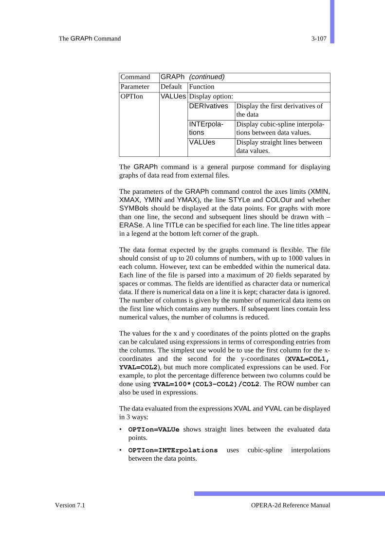
The GRAPh Command 3-107
ing
oreith –ar
files in
data. byericalored.s on less
aphs frome x-
Forld be
ata
The GRAPh command is a general purpose command for displaygraphs of data read from external files.
The parameters of the GRAPh command control the axes limits (XMIN,XMAX, YMIN and YMAX), the line STYLe and COLOur and whetherSYMBols should be displayed at the data points. For graphs with mthan one line, the second and subsequent lines should be drawn wERASe. A line TITLe can be specified for each line. The line titles appein a legend at the bottom left corner of the graph.
The data format expected by the graphs command is flexible. Theshould consist of up to 20 columns of numbers, with up to 1000 valueeach column. However, text can be embedded within the numerical Each line of the file is parsed into a maximum of 20 fields separatedspaces or commas. The fields are identified as character data or numdata. If there is numerical data on a line it is kept; character data is ignThe number of columns is given by the number of numerical data itemthe first line which contains any numbers. If subsequent lines containnumerical values, the number of columns is reduced.
The values for the x and y coordinates of the points plotted on the grcan be calculated using expressions in terms of corresponding entriesthe columns. The simplest use would be to use the first column for thcoordinates and the second for the y-coordinates (XVAL=COL1,YVAL=COL2), but much more complicated expressions can be used.example, to plot the percentage difference between two columns coudone using YVAL=100*(COL3-COL2)/COL2 . The ROW number canalso be used in expressions.
The data evaluated from the expressions XVAL and YVAL can be displayedin 3 ways:
• OPTIon=VALUe shows straight lines between the evaluated dpoints.
• OPTIon=INTErpolations uses cubic-spline interpolationsbetween the data points.
OPTIon VALUes Display option:DERIvatives Display the first derivatives of
the dataINTErpola-tions
Display cubic-spline interpola-tions between data values.
VALUes Display straight lines between data values.
Command GRAPh (continued)Parameter Default Function
Version 7.1 OPERA-2d Reference Manual
3-108 Chapter 3 - The Pre and Post-Processor
-
r
• OPTIon=DERIvatives shows the first derivative of the cubicspline interpolations.
INTErpolations and DERIvatives can only be used if the expression foXVAL results in a monotonically increasing set of values.
OPERA-2d Reference Manual 27 September 1999
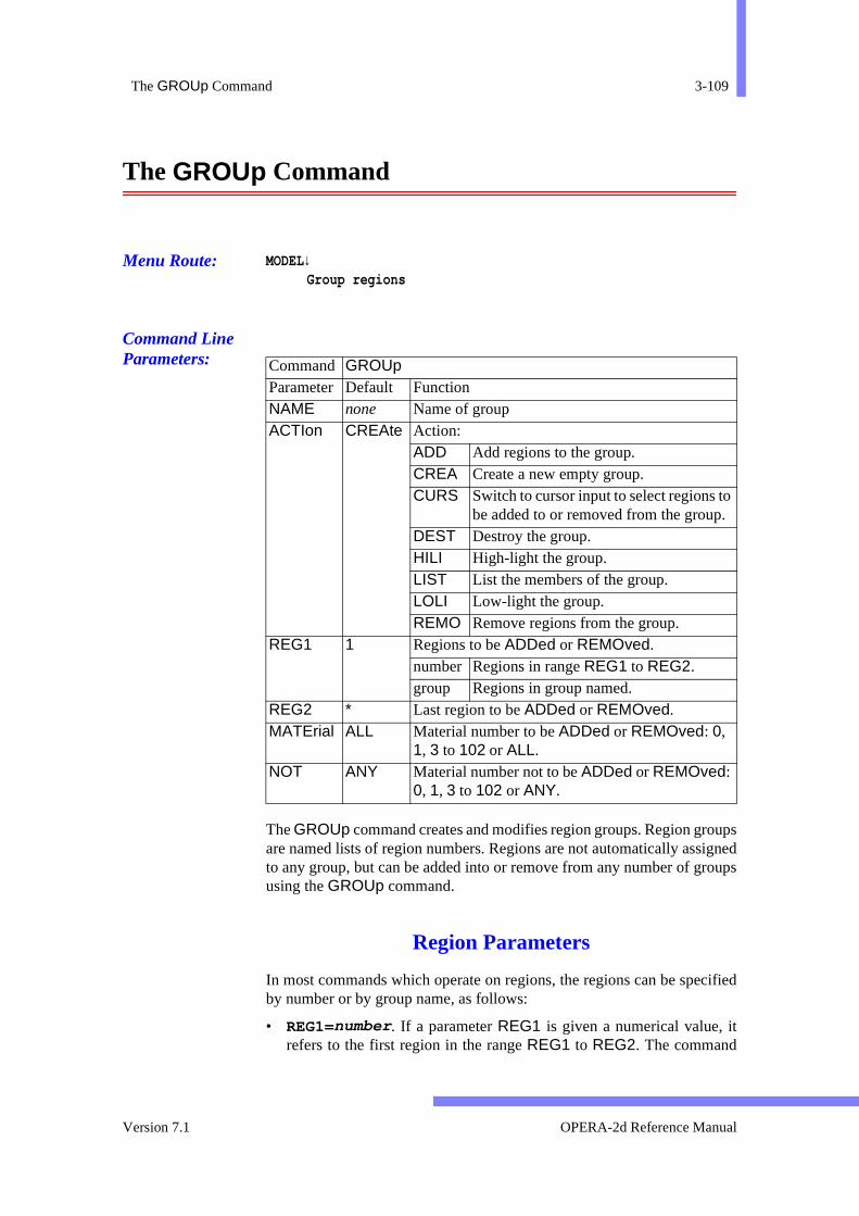
The GROUp Command 3-109
upsignedoups
cified
The GROUp Command
Menu Route: MODEL↓Group regions
Command Line Parameters:
The GROUp command creates and modifies region groups. Region groare named lists of region numbers. Regions are not automatically assto any group, but can be added into or remove from any number of grusing the GROUp command.
Region Parameters
In most commands which operate on regions, the regions can be speby number or by group name, as follows:
• REG1=number . If a parameter REG1 is given a numerical value, itrefers to the first region in the range REG1 to REG2. The command
Command GROUp Parameter Default Function NAME none Name of group ACTIon CREAte Action:
ADD Add regions to the group. CREA Create a new empty group. CURS Switch to cursor input to select regions to
be added to or removed from the group.DEST Destroy the group. HILI High-light the group. LIST List the members of the group. LOLI Low-light the group. REMO Remove regions from the group.
REG1 1 Regions to be ADDed or REMOved. number Regions in range REG1 to REG2. group Regions in group named.
REG2 * Last region to be ADDed or REMOved. MATErial ALL Material number to be ADDed or REMOved: 0,
1, 3 to 102 or ALL. NOT ANY Material number not to be ADDed or REMOved:
0, 1, 3 to 102 or ANY.
Version 7.1 OPERA-2d Reference Manual

3-110 Chapter 3 - The Pre and Post-Processor
m-ye.
or
,n the
the
can.
ers
n be
rs of
hed on
em-
ur.
ol-
the
d or
ted
then operates on all the regions from REG1 to REG2. REG2 can begiven the value * to indicate the highest numbered region. In some comands, parameters MATErial and NOT can also be used to include onlone material within the range or exclude one material from the rang
N.B. The text function %int() must be used to evaluate expressionsuser variables as values for REG1 or REG2 (see page 2-17).
• REG1=group_name . If a parameter REG1 is given a character valueit refers to a region group. In this case the command operates omembers of that group. The parameters REG2, MATErial and NOT areignored.
Region groups definitions are read from and stored in data files byREAD and WRITe commands (see page 3-147 andpage 3-182).
GROUp Command Actions
The first parameter of the GROUp command is the NAME. This can beany character string of up to 8 characters. It must start with a letter. In menumode, the names of existing groups appear in a DialogBox so that onebe selected. In keyboard mode, use NAME=! to obtain a list of group names
The GROUp command has 8 actions, selected by the ACTIon parameter:
• CREAte: this creates an empty group with a new NAME.
• DESTroy: this destroys an existing group by removing all its membare deleting its name from the list. It does not ERASe the regions.
• ADD: this adds the regions specified to the group. The regions caspecified by number or by group name as described in page 3-109above. It does not matter if some of the regions are already membethe group.
• REMOve: this removes the regions specified from the group. Tregions can be specified by number or by group name as describepage 3-109 above. It does not matter if some of the regions are not mbers of the group.
• HILIght: this repaints the members of the group in the high-light colo
• LOLIght: this repaints the members of the group in their material cours.
• LIST: this list the numbers of the regions which are members of group.
• CURSor: this switches to cursor input so that regions to be adderemoved from the group can be picked from the display (see page 3-133). The group is high-lighted on entry to cursor mode and low-ligh
OPERA-2d Reference Manual 27 September 1999
The GROUp Command 3-111
on exit. There are 4 valid cursor hit characters: A for add, R for remove,H for help and Q for quit.
Version 7.1 OPERA-2d Reference Manual
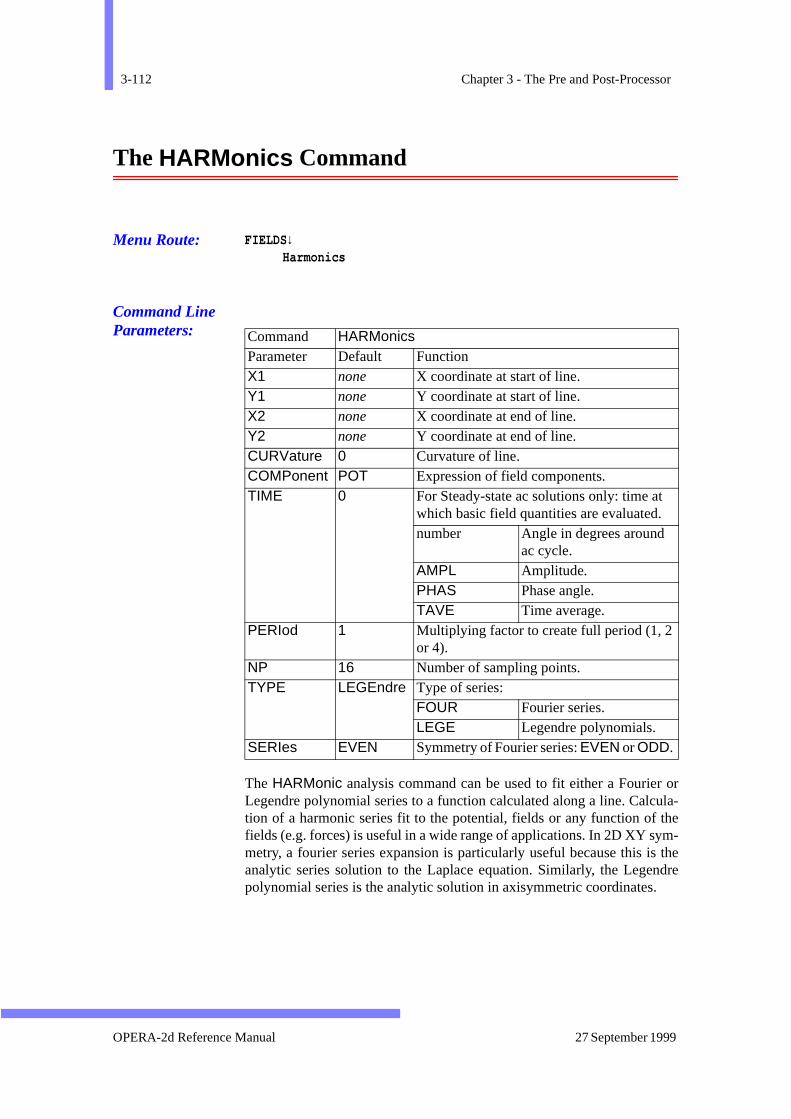
3-112 Chapter 3 - The Pre and Post-Processor
r orula-them-
s thedre
The HARMonics Command
Menu Route: FIELDS↓Harmonics
Command Line Parameters:
The HARMonic analysis command can be used to fit either a FourieLegendre polynomial series to a function calculated along a line. Calction of a harmonic series fit to the potential, fields or any function of fields (e.g. forces) is useful in a wide range of applications. In 2D XY symetry, a fourier series expansion is particularly useful because this ianalytic series solution to the Laplace equation. Similarly, the Legenpolynomial series is the analytic solution in axisymmetric coordinates.
Command HARMonics Parameter Default Function X1 none X coordinate at start of line. Y1 none Y coordinate at start of line. X2 none X coordinate at end of line. Y2 none Y coordinate at end of line. CURVature 0 Curvature of line. COMPonent POT Expression of field components. TIME 0 For Steady-state ac solutions only: time at
which basic field quantities are evaluated. number Angle in degrees around
ac cycle. AMPL Amplitude. PHAS Phase angle. TAVE Time average.
PERIod 1 Multiplying factor to create full period (1, 2 or 4).
NP 16 Number of sampling points. TYPE LEGEndre Type of series:
FOUR Fourier series. LEGE Legendre polynomials.
SERIes EVEN Symmetry of Fourier series: EVEN or ODD.
OPERA-2d Reference Manual 27 September 1999
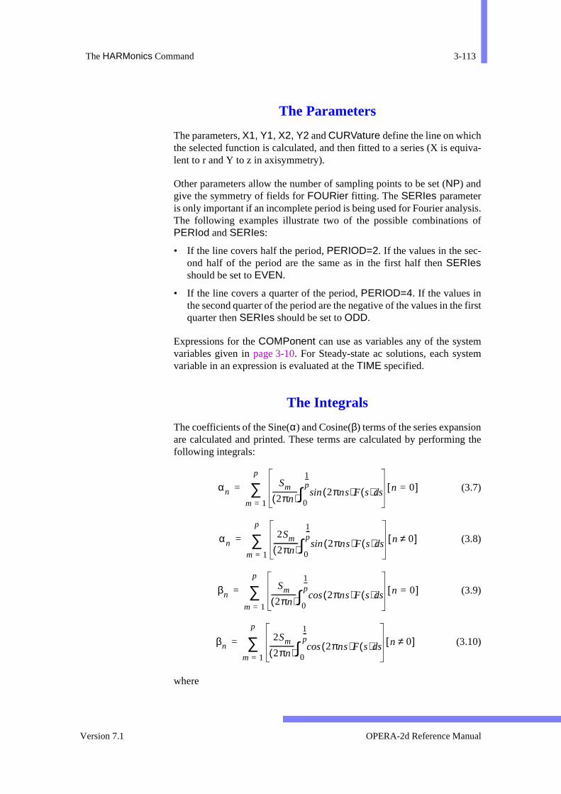
The HARMonics Command 3-113
uiva-
sis. of
first
mem
ng the
The Parameters
The parameters, X1, Y1, X2, Y2 and CURVature define the line on whichthe selected function is calculated, and then fitted to a series (X is eqlent to r and Y to z in axisymmetry).
Other parameters allow the number of sampling points to be set (NP) andgive the symmetry of fields for FOURier fitting. The SERIes parameteris only important if an incomplete period is being used for Fourier analyThe following examples illustrate two of the possible combinationsPERIod and SERIes:
• If the line covers half the period, PERIOD=2. If the values in the sec-ond half of the period are the same as in the first half then SERIesshould be set to EVEN.
• If the line covers a quarter of the period, PERIOD=4. If the values inthe second quarter of the period are the negative of the values in thequarter then SERIes should be set to ODD.
Expressions for the COMPonent can use as variables any of the systevariables given in page 3-10. For Steady-state ac solutions, each systvariable in an expression is evaluated at the TIME specified.
The Integrals
The coefficients of the Sine(α) and Cosine(β) terms of the series expansioare calculated and printed. These terms are calculated by performinfollowing integrals:
(3.7)
(3.8)
(3.9)
(3.10)
where
αnSm
2πn( )-------------- 2πns( )Fsin s( ) sd
0
1p---
∫ n 0=[ ]m 1=
p
∑=
αn2Sm
2πn( )-------------- 2πns( )Fsin s( ) sd
0
1p---
∫ n 0≠[ ]m 1=
p
∑=
βnSm
2πn( )-------------- 2πns( )Fcos s( ) sd
0
1p---
∫ n 0=[ ]m 1=
p
∑=
βn2Sm
2πn( )-------------- 2πns( )Fcos s( ) sd
0
1p---
∫ n 0≠[ ]m 1=
p
∑=
Version 7.1 OPERA-2d Reference Manual
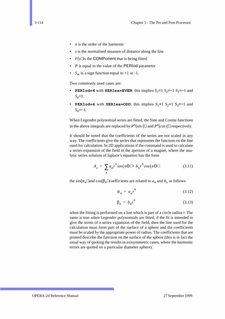
3-114 Chapter 3 - The Pre and Post-Processor
tions
any linelate ana-
d tor theientst aret theonic
• n is the order of the harmonic
• s is the normalised measure of distance along the line
• F(s) is the COMPonent that is being fitted
• P is equal to the value of the PERIod parameter
• Sm is a sign function equal to +1 or -1.
Two commonly used cases are:
• PERIod=4 with SERIes=EVEN: this implies S1=1 S2=−1 S3=−1 andS4=1.
• PERIod=4 with SERIes=ODD: this implies S1=1 S2=1 S3=−1 andS4=−1.
When Legendre polynomial series are fitted, the Sine and Cosine func
in the above integrals are replaced by Pn(sin ()) and Pn(cos ()) respectively.
It should be noted that the coefficients of the series are not scaled inway. The coefficients give the series that represents the function on theused for calculation. In 2D applications if the command is used to calcua series expansion of the field in the aperture of a magnet, where thelytic series solution of laplace’s equation has the form
(3.11)
the sin(αn) and cos(βn) coefficients are related to an and bn as follows
(3.12)
(3.13)
when the fitting is performed on a line which is part of a circle radius r. Thesame is true when Legendre polynomials are fitted, if the fit is intendegive the terms of a series expansion of the field, then the line used focalculation must form part of the surface of a sphere and the coefficmust be scaled by the appropriate power of radius. The coefficients thaprinted describe the function on the surface of the sphere (this is in facusual way of quoting the results in axisymmetric cases, where the harmerrors are quoted on a particular diameter sphere).
Az anrn
nΘ( )sin bnrn
nΘ( )cos+
n
∑=
αn anrn
=
βn bnrn
=
OPERA-2d Reference Manual 27 September 1999
The HARMonics Command 3-115
eries thatThe atrrors
n at on
thenits,
parther-riod
Practical hints • When this command is used to determine the coefficients of a s
expansion of the field in the aperture of a magnet, it should be notedit is good practice to use a large radius for the function evaluation. high order harmonics will only make a small contribution to the fielda small radius and may therefore be invisible (or subject to large edue to numerical inaccuracies).
• To determine the Legendre polynomial expansion of the field osphere, the line used to calculate the fields should start from a poinaxis. For example, if the field has symmetry about the plane Z=0,command to fit the Z component of the field, on a sphere radius 25 uis
HARM TYPE=LEGENDRE X1=0 Y1=25 X2=25 Y2=0,CURV=1/25 PERIOD=2 COMP=BZ
• If the function has a zero order term and the fit is only performed on of the full period, then the zero order term must be subtracted. Otwise, the sign reflection used to extend the function to the full pewill not produce the expected result.
Version 7.1 OPERA-2d Reference Manual
3-116 Chapter 3 - The Pre and Post-Processor
ures
-
lpands
or
g
d-
The HELP Command
Menu Route: HELP
Command Line Parameters:
The HELP command gives help to remind users of several of the featof the program. The topics are:
• System Overview: this gives an overview of OPERA-2d and introduces the other HELP topics.
• Command Interpreter: this summarizes the syntax and built-in hefeatures of the command decoder, including details of sub-command cursor commands. More information is given in chapter 2.
• Data Definition Commands: this summarizes the commands used fentering data.
• Post-processing Commands: this summarizes the post-processincommands and lists the system variables currently available.
• File Handling Commands: this summarizes the commands for reaing, writing, deleting, renaming and listing files.
The program prompts for the name of a topic: SYSTem, COMMand,DEFIne, POST, SYSTem or QUIT.
When accessed from the GUI, the HELP command has different topicsexplaining the use of the program and the menu interface.
Command HELPNo Parameters
OPERA-2d Reference Manual 27 September 1999
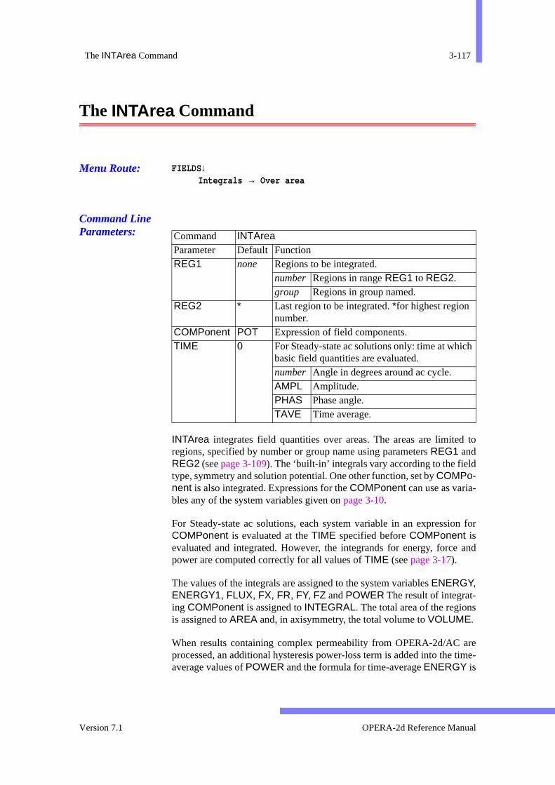
The INTArea Command 3-117
d to
n for
and
are time-
h
The INTArea Command
Menu Route: FIELDS↓Integrals → Over area
Command Line Parameters:
INTArea integrates field quantities over areas. The areas are limiteregions, specified by number or group name using parameters REG1 andREG2 (see page 3-109). The ‘built-in’ integrals vary according to the fieldtype, symmetry and solution potential. One other function, set by COMPo-nent is also integrated. Expressions for the COMPonent can use as varia-bles any of the system variables given on page 3-10.
For Steady-state ac solutions, each system variable in an expressioCOMPonent is evaluated at the TIME specified before COMPonent isevaluated and integrated. However, the integrands for energy, forcepower are computed correctly for all values of TIME (see page 3-17).
The values of the integrals are assigned to the system variables ENERGY,ENERGY1, FLUX, FX, FR, FY, FZ and POWER The result of integrat-ing COMPonent is assigned to INTEGRAL. The total area of the regionsis assigned to AREA and, in axisymmetry, the total volume to VOLUME.
When results containing complex permeability from OPERA-2d/AC processed, an additional hysteresis power-loss term is added into theaverage values of POWER and the formula for time-average ENERGY is
Command INTArea Parameter Default Function REG1 none Regions to be integrated.
number Regions in range REG1 to REG2. group Regions in group named.
REG2 * Last region to be integrated. *for highest region number.
COMPonent POT Expression of field components. TIME 0 For Steady-state ac solutions only: time at whic
basic field quantities are evaluated. number Angle in degrees around ac cycle. AMPL Amplitude. PHAS Phase angle. TAVE Time average.
Version 7.1 OPERA-2d Reference Manual
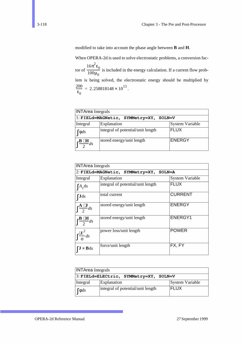
3-118 Chapter 3 - The Pre and Post-Processor
fac-
b-
by
modified to take into account the phase angle between B and H.
When OPERA-2d is used to solve electrostatic problems, a conversion
tor of is included in the energy calculation. If a current flow pro
lem is being solved, the electrostatic energy should be multiplied
.
INTArea Integrals 1: FIELd=MAGNetic, SYMMetry=XY, SOLN=V
Integral Explanation System Variable integral of potential/unit length FLUX
stored energy/unit length ENERGY
INTArea Integrals 2: FIELd=MAGNetic, SYMMetry=XY, SOLN=A
Integral Explanation System Variable integral of potential/unit length FLUX
total current CURRENT
stored energy/unit length ENERGY
stored energy/unit length ENERGY1
power loss/unit length POWER
force/unit length FX, FY
INTArea Integrals 3: FIELd=ELECtric, SYMMetry=XY, SOLN=V
Integral Explanation System Variable integral of potential/unit length FLUX
16π2ε0
100µ0------------------
200ε0
--------- 2.258818148 1013×=
φds∫B H⋅
2-------------ds∫
Azds∫Jds∫A J⋅
2-----------ds∫B H⋅
2-------------ds∫J 2
σ--------ds∫J Bds×∫
φds∫
OPERA-2d Reference Manual 27 September 1999
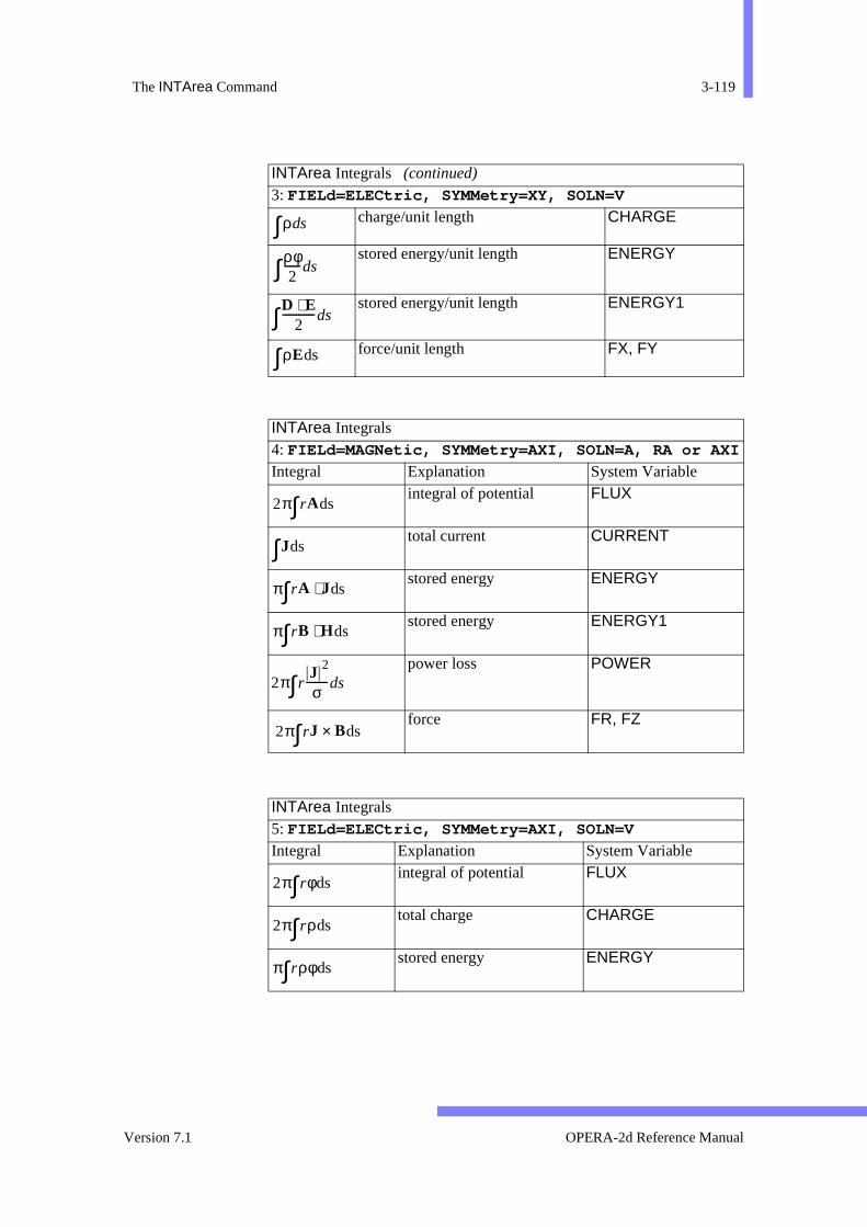
The INTArea Command 3-119
charge/unit length CHARGE
stored energy/unit length ENERGY
stored energy/unit length ENERGY1
force/unit length FX, FY
INTArea Integrals 4: FIELd=MAGNetic, SYMMetry=AXI, SOLN=A, RA or AXI
Integral Explanation System Variable integral of potential FLUX
total current CURRENT
stored energy ENERGY
stored energy ENERGY1
power loss POWER
force FR, FZ
INTArea Integrals 5: FIELd=ELECtric, SYMMetry=AXI, SOLN=V
Integral Explanation System Variable integral of potential FLUX
total charge CHARGE
stored energy ENERGY
INTArea Integrals (continued)
3: FIELd=ELECtric, SYMMetry=XY, SOLN=V
ρds∫ρφ2
------ds∫D E⋅
2------------ds∫ρEds∫
2π rAds∫Jds∫
π rA Jds⋅∫π rB Hds⋅∫
2π rJ 2
σ--------ds∫
2π rJ Bds×∫
2π rφds∫2π rρds∫π rρφds∫
Version 7.1 OPERA-2d Reference Manual
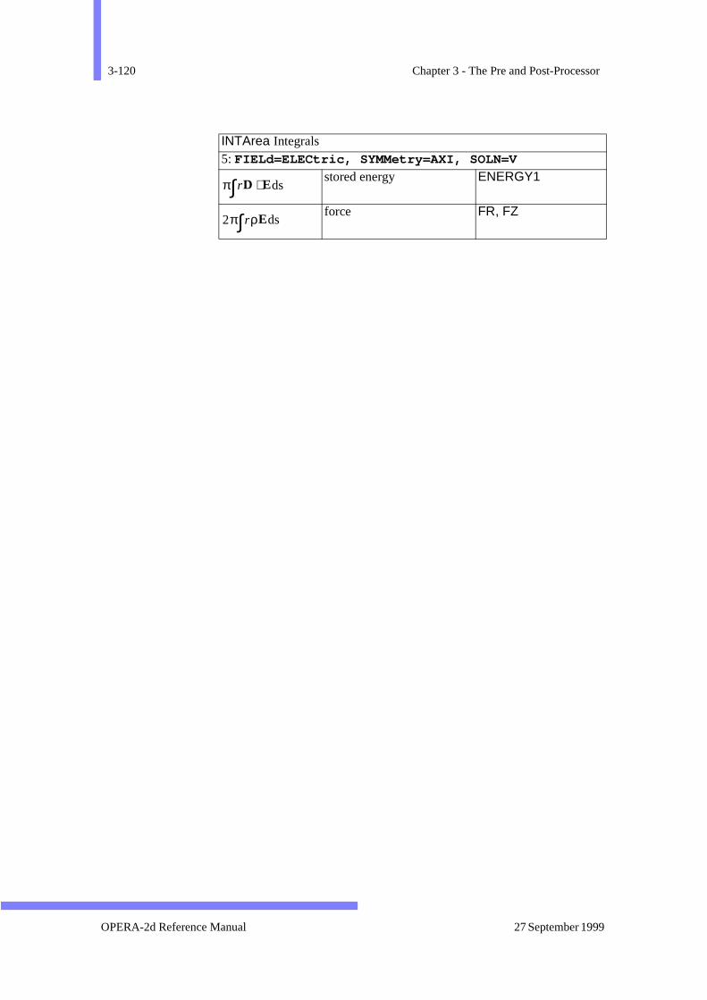
3-120 Chapter 3 - The Pre and Post-Processor
stored energy ENERGY1
force FR, FZ
INTArea Integrals 5: FIELd=ELECtric, SYMMetry=AXI, SOLN=V
π rD Eds⋅∫2π rρEds∫
OPERA-2d Reference Manual 27 September 1999

The INTCircle Command 3-121
rc.ts,
.
The INTCircle Command
Menu Route: FIELDS↓Integrals → Around circular arc
Command Line Parameters:
The INTCircle command integrates field quantities along a circular adefined by its RADIus and the azimuthal coordinates of the end poin(P1, P2). Integrals along can also be done using the INTLine command(page 3-123).
Command INTCircle Parameter Default Function RADIus none Radius of arc. P1 none Azimuthal coordinate at start of arc. P2 none Azimuthal coordinate at end of arc. XCENtre 0 X coordinate at centre of arc. YCENtre 0 Y coordinate at centre of arc. COMPonent POT Expression of field components. TIME 0 For Steady-state ac solutions only: time at
which basic field quantities are evaluated. number Angle in degrees around ac cycle. AMPL Amplitude. PHAS Phase angle. TAVE Time average.
ERROr 0.01 If ERROr<1 it is used as the tolerance in a Runge-Kutta integration. If ERROr≥1 it is used as the number of points in a Simpson’s Rule integration.
XACTion 0 X coordinate of torque action point. YACTion 0 Y coordinate of torque action point. ACCUmulator ZERO Accumulator options:
ADD Add integrals to accumulator. SUBT Subtract integrals from accumulator. ZERO Zero accumulator, then add integrals
AVERage YES Nodally averaged fields switch: NO Use shape function derivative fields. YES Use nodally averaged field.
Version 7.1 OPERA-2d Reference Manual
3-122 Chapter 3 - The Pre and Post-Processor
unit the
m
n for
rationt the
ely inon orrfaceough van- sin-
ressrec-
val-
The functions integrated are:
• in xy coordinates: the Maxwell Stress, to give the x and y force per length and the anticlockwise torque per unit length with respect toaction point (XACTion, YACTion).
• in axisymmetry: the Maxwell Stress, to give the z force.
• one other COMPonent.
Expressions for the COMPonent can use as variables any of the systevariables given in page 3-10.
For Steady-state ac solutions, each system variable in an expressioCOMPonent is evaluated at the TIME specified. However, the integralsfor force and torque are computed correctly for all values of TIME. (Seepage 3-17.)
The values of the integrals are assigned to the system variables INTE-GRAL and in xy coordinates, FX, FY and TORQUE, or in axisymmetry,FZ.
The integrals can be evaluated using nodally averaged fields (+AVERage)or shape function derivative fields (-AVERage). The ERROr can also beset to a value less than 1 to achieve a particular accuracy on the integusing a Runge-Kutta method or to a number greater than 1 to senumber of steps in a Simpson’s Rule integration.
For best results, it is recommended that integration paths are completair and do not pass through elements which touch the surface of any irdielectric. The reason for this is that close to positions where the sutangent direction changes, the errors will be large. If the line passes thrnon-air materials, the Maxwell stresses are evaluated as if the line is aishingly narrow cut in the material. This should be used with care sincegular points at the ends of the cut can lead to a loss of accuracy.
The total force on a body should be computed from the Maxwell Stintegral along series of lines encircling the body in an anticlockwise dition. To enable the forces to be summed easily, an ACCUmulator can beinitialized to ZERO and the integrals ADDed to or SUBTracted from it.INTCircle and INTLine share the same accumulator. The accumulated ues are not stored in system variables.
OPERA-2d Reference Manual 27 September 1999

The INTLine Command 3-123
by
’s
The INTLine Command
Menu Route: FIELDS↓Integrals → Along line
Command Line Parameters:
The INTLine command integrates field quantities along a line, defined
Command INTLine Parameter Default Function X1 none X coordinate at start of line. Y1 none Y coordinate at start of line. X2 none X coordinate at end of line. Y2 none Y coordinate at end of line. CURVature 0 Curvature of line. COMPonent POT Expression of field components. TIME 0 For Steady-state ac solutions only: time at
which basic field quantities are evaluated.number Angle in degrees around ac
cycle. AMPL Amplitude. PHAS Phase angle. TAVE Time average.
ERROr 0.01 If ERROr<1 it is used as the tolerance in aRunge-Kutta integration. If ERROr≥1 it is used as the number of points in a SimpsonRule integration.
XACTion 0 X coordinate of torque action point. YACTion 0 Y coordinate of torque action point. ACCUmulator ZERO Accumulator options:
ADD Add integrals to accumulator. SUBT Subtract integrals from accumu-
lator. ZERO Zero accumulator, then add inte-
grals. AVERage YES Nodally averaged fields switch:
NO Use shape function derivative fields.
YES Use nodally averaged field.
Version 7.1 OPERA-2d Reference Manual
3-124 Chapter 3 - The Pre and Post-Processor
unit the
m
n for
rationt the
ely inon orrfaceough van- sin-
ressrec-
val-
its end points, (X1, Y1) and (X2, Y2) and its CURVature. Integrals on cir-cular arcs can also be done using the INTCircle command (page 3-121).
The functions integrated are:
• in xy coordinates: the Maxwell Stress, to give the x and y force per length and the anticlockwise torque per unit length with respect toaction point (XACTion, YACTion).
• in axisymmetry: the Maxwell Stress, to give the z force.
• one other COMPonent.
Expressions for the COMPonent can use as variables any of the systevariables given in page 3-10.
For Steady-state ac solutions, each system variable in an expressioCOMPonent is evaluated at the TIME specified. However, the integralsfor force and torque are computed correctly for all values of TIME. (Seepage 3-17.)
The values of the integrals are assigned to the system variables INTE-GRAL and in xy coordinates, FX, FY and TORQUE, or in axisymmetry,FZ.
The integrals can be evaluated using nodally averaged fields (+AVERage)or shape function derivative fields (-AVERage). The ERROr can also beset to a value less than 1 to achieve a particular accuracy on the integusing a Runge-Kutta method or to a number greater than 1 to senumber of steps in a Simpson’s Rule integration.
For best results, it is recommended that integration paths are completair and do not pass through elements which touch the surface of any irdielectric. The reason for this is that close to positions where the sutangent direction changes, the errors will be large. If the line passes thrnon-air materials, the Maxwell stresses are evaluated as if the line is aishingly narrow cut in the material. This should be used with care sincegular points at the ends of the cut can lead to a loss of accuracy.
The total force on a body should be computed from the Maxwell Stintegral along series of lines encircling the body in an anticlockwise dition. To enable the forces to be summed easily, an ACCUmulator can beinitialized to ZERO and the integrals ADDed to or SUBTracted from it.INTLine and INTCircle share the same accumulator. The accumulated ues are not stored in system variables.
OPERA-2d Reference Manual 27 September 1999

The LINE Command 3-125
The LINE Command
Menu Route: FIELDS↓Graphs → Along line
Command Line Parameters:
Command LINE Parameter Default Function X1 none X coordinate at start of line. Y1 none Y coordinate at start of line. X2 none X coordinate at end of line. Y2 none Y coordinate at end of line. NP 10 Number of steps along line,i.e. NP+1 points. CURVature 0 Curvature of line. COMPonent POT Expression of field components. TIME 0 For Steady-state ac solutions only: time at
which basic field quantities are evaluated. number Angle in degrees around ac cycle. AMPL Amplitude. PHAS Phase angle. TAVE Time average.
AVERage YES Nodally averaged fields switch: NO Use shape function derivative fields.YES Use nodally averaged field.
GRAPh YES Graph display switch: NO No graph. YES Values displayed as graph.
PRINt NO Printed values switch: NO Values printed to file opera2.lp. YES Values printed to screen and file
opera2.lp. AUTOmatic YES Automatic graph scale switch:
NO Vertical axis limits set by VMIN and VMAX.
YES Vertical axis set automatically. VMAX none Upper limit of vertical axis of graph AUTO-
matic=NO.
Version 7.1 OPERA-2d Reference Manual
3-126 Chapter 3 - The Pre and Post-Processor
its
m of
g,
n for-
theet
The LINE command calculates field quantities along a line, defined byend points, (X1, Y1) and (X2, Y2) and its CURVature and displays themas tables of numbers and graphs. The field is evaluated at NP+1 points.Calculation of field values along lines can also be done using the CIRClecommand (page 3-25) and the PLOT command (page 3-109).
Expressions for the COMPonent can use as variables any of the systevariables given in page 3-10. The values used can be the actual valuesCOMPonent or the HOMOgeneity of the COMPonent with respect tothe reference point (XREF, YREF). The homogeneity is evaluated usine.g.
(3.14)
For Steady-state ac solutions, each system variable in an expressioCOMPonent is evaluated at the TIME specified. The values can be evaluated using nodally averaged fields (+AVERage) or shape function deriva-tive fields (-AVERage).
The user can choose whether or not to see PRINted tables of values orGRAPhs. PRINted values appear on the screen and are also written todialogue file opera2.lp. The graphs can have the vertical axis limits sAUTOmatically or by the values of VMAX and VMIN with -AUTO-matic .
VMIN none Lower limit of vertical axis of graph AUTO-matic=NO.
ERASe YES Old graph erasure switch: NO New line drawn on existing axes. YES Graphics window cleared and new
axes drawn. LTYPe 6 Line type or colour. TITLe none Additional title for line. HOMOgeneity NO Homogeneity switch:
NO Values of COMPonent used. YES Homogeneity with respect to COM-
Ponent value at XREF,YREF used. XREF 0 X or R coordinate of homogeneity reference
point. YREF 0 Y or Z coordinate of homogeneity reference
point.
Command LINE (continued)
Parameter Default Function
Ahomo
A x y,( ) A xref yref,( )–
A xref yref,( )---------------------------------------------------=
OPERA-2d Reference Manual 27 September 1999

The LINE Command 3-127
ayed
eit isota-
s-
Multiple lines can be displayed on the same axes, the first being displwith +ERASe, and the rest with -ERASe. The lines can be displayed withdifferent line styles (on monochrome displays) or colours (LTYPe), and aTITLe in addition to the COMPonent can be added to the key below thgraph. The TITLe is not remembered and must be supplied each time needed. TITLes including spaces or commas should be enclosed in qution marks (’ ).
The MINIMUM and MAXIMUM values along the line are assigned to sytem variables.
Version 7.1 OPERA-2d Reference Manual

3-128 Chapter 3 - The Pre and Post-Processor
se ofblemmentmand
there(see
nodesloser
The MESH Command
Menu Routes: Equivalent to MESH ERROr=NO: FILE ↓
Read file → Re-mesh
Equivalent to MESH ERROr=YES:
MODEL↓Mesh generator → Generate mesh
Command Line Parameters:
The complete finite element mesh can be generated at any time by uthe MESH command. This forms the data necessary to analyse the proor interrogate the results, i.e. node table, element definition table, eleproperties, boundary nodes, etc. It is essential to use the mesh comafter DRAWing the regions, and before WRITing a data file for analysis,in order to check the data given. The nodes with boundary conditions othan NO and the mesh in a Background region can be displayed using thRECOnstruct command only after the mesh has been generated page 3-149).
As each region is added to the mesh, the program removes redundantwhere two regions meet. This is done by coalescing nodes which are cthan the tolerance. By default, the tolerance is
5×10⁻⁵ × |(maximum coordinate of region being added)|
Command MESH Parameter Default Function TOLErance 5.0E-5 Coincidence tolerance on joining regions
together. DISPlay NO Polygon mesh display switch:
NO No mesh generator display. YES Display the activity of polygon mesh gen-
erator. ERROr YES Check and display errors in the mesh:
NO No error checking. YES Error checking.
DELEte NO Delete existing mesh and solution data: NO Do not delete. YES Delete.
OPERA-2d Reference Manual 27 September 1999
The MESH Command 3-129
extra
totorilyhich alsof the
are
ct-eral
the
tacanoids
and
but the factor, 5×10⁻⁵ can be changed using the TOLErance parameter.The tolerance is included in any data file WRITten, and if the mesh has tobe generated for post-processing, the value READ from the results file willbe used unless a value is given on the MESH command.
During mesh generation in POLYgonal regions, the activity of the meshgenerator can be displayed. This shows the initial mesh, insertion of nodes and relaxation of node positions. The DISPlay parameter switchesthis facility on and off.
• If ERROr=YES, the program displays the boundary of the mesh,show whether redundant nodes have been eliminated satisfacwhere regions touch. This display consists of all element edges wdo not occur twice. Thus adjacent regions which do not match areshown. In keyboard mode, the user has opportunity to display part oboundary by changing the area shown in the same way as in the ZOOMcommand. The error check display can be redisplayed using
DISPLAY↓Style → Mesh error check
→ ReturnRefresh
equivalent to the command, RECO FILL=ERROr (see page 3-149).Errors can be corrected automatically using the TEST command(page 3-166) or by hand using the MODIfy command (page 3-130).
• Also with ERROr=YES, the total numbers of nodes and elements given and nodes with boundary conditions other than NO are displayed.The MESH command then automatically runs the CHECk command tocheck the data. If any errors are found the mesh will not be stored.
• The option ERROr=NO allows the mesh to be generated without affeing the display. This can be useful in overlaying results from sevfiles, when the mesh files have been deleted.
Any command which changes the stored data (DRAW, COPY, ERASE,MODIfy, SET, SYMMetry, TEST) can also destroy the mesh data.
After loading in an RM solution, the model can not be modified until mesh and the solution data has been removed with DELEte=YES.
If the mesh data exists when the WRITe command is used, the mesh dawill also be stored in a file. Similarly, an appropriately named mesh file be READ into the program, at the same time as the region data. This avexpensive recalculation of mesh data (see page 3-147 and page 3-182).
The program maintains an ‘extra’ title block (see page 3-168) at the rightof the graphics window including ‘No Mesh’ or the numbers of nodes elements as appropriate.
Version 7.1 OPERA-2d Reference Manual

3-130 Chapter 3 - The Pre and Post-Processor
andedited
ode,
ursorg to
tion,g the
m-
the
The MODIfy Command
The MODIfy command is the main data editing command for the Pre Post-Processor. Corners and face properties of regions can also be using the EDIT command (page 3-72).
MODIfy can be used in two ways: keyboard or cursor. In keyboard mparameters are used to specify which regions are to be MODIfied and todefine new values for some of the parameters of those regions. In cmode a point (region corner), face or region can be chosen by pointinit on the graphics window, and then new values can be given for posiface properties or region properties. Cursor mode is selected by issuinMODIfy command with no parameters.
Before each MODIfy command, the current set of regions is saved in meory so that it can be restored using the UNDO command (page 3-172) ifregions are modified in error.
Keyboard MODIfy
Menu Route: MODEL↓Modify regions → Region group
→ Multiple regions
If any parameters are given on a MODIfy command, keyboard mode isassumed.
The MODIfy command has 63 parameters, the last 60 of which aresame as the parameters of the DRAW command (page 3-43). The first 3select the range of regions to be MODIfied and whether the picture of theregions should be RECOnstructed afterwards (page 3-149).
Command Line Parameters (first 3):
Command MODIfy: The first 3 parameters. Parameter Default Function REG1 none Regions to be modified.
number Regions in range REG1 to REG2. group Regions in group named.
REG2 REG1 Last region to be modified. *for highest region number.
OPERA-2d Reference Manual 27 September 1999
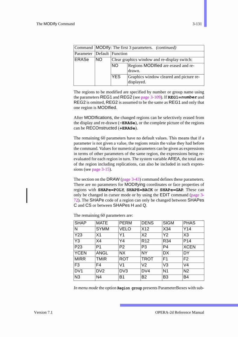
The MODIfy Command 3-131
sing
oms
at if aefore
ssionsng re-
res-
rs.f
b-
The regions to be modified are specified by number or group name uthe parameters REG1 and REG2 (see page 3-109). If REG1=number andREG2 is omitted, REG2 is assumed to be the same as REG1 and only thatone region is MODIfied.
After MODIfications, the changed regions can be selectively erased frthe display and re-drawn (-ERASe), or the complete picture of the regioncan be RECOnstructed (+ERASe).
The remaining 60 parameters have no default values. This means thparameter is not given a value, the regions retain the value they had bthe command. Values for numerical parameters can be given as exprein terms of other parameters of the same region, the expressions beievaluated for each region in turn. The system variable AREA, the total areaof the region including replications, can also be included in such expsions (see page 3-15).
The section on the DRAW (page 3-43) command defines these parameteThere are no parameters for MODIfying coordinates or face properties oregions with SHAPe=POLY, SHAPE=BACK or SHAPe=GAP. These canonly be changed in cursor mode or by using the EDIT command (page 3-72). The SHAPe code of a region can only be changed between SHAPesC and CS or between SHAPes H and Q.
The remaining 60 parameters are:
In menu mode the option Region group presents ParameterBoxes with su
ERASe NO Clear graphics window and re-display switch: NO Regions MODIfied are erased and re-
drawn. YES Graphics window cleared and picture re-
displayed.
SHAP MATE PERM DENS SIGM PHAS N SYMM VELO X12 X34 Y14 Y23 X1 Y1 X2 Y2 X3 Y3 X4 Y4 R12 R34 P14 P23 P1 P2 P3 P4 XCEN YCEN ANGL NX NY DX DY MIRR TMIR ROT TROT F1 F2 F3 F4 V1 V2 V3 V4 DV1 DV2 DV3 DV4 N1 N2 N3 N4 B1 B2 B3 B4
Command MODIfy: The first 3 parameters. (continued)
Parameter Default Function
Version 7.1 OPERA-2d Reference Manual

3-132 Chapter 3 - The Pre and Post-Processor
eters
nto a
r withOther pic-
rthe-
ares farions
and up).
data
n
sets of the parameters. Values should only be given for the paramwhich should be changed.
In menu mode the option Multiple regions allows the values of REG1and REG2 and up to 4 parameter names and values to be entered iDialogBox.
Cursor MODIfy
If no parameters are given on a MODIfy command, cursor mode isassumed.
In the cursor mode of the MODIfy command, items (points, faces oregions) to be changed are selected by pointing to them on the displaythe cursor, and using one of the single character cursor commands. cursor commands allow extra points to be inserted into polygons, theture to be re-drawn or to obtain help.
Region corners can be moved with the N, P and T cursor hits. If a regioncorner is selected to be moved with N, all regions which share that corneare modified. If P is used for selection, then only the region containing cursor position is changed. Cursor hit T introduces a transformation operation, allowing many region corners to be moved in the same way.
Faces can be selected for changes to their parameters with the F cursor hit.When an internal face is modified, both regions which share the facemodified, and any change in subdivision is carried through the mesh aas possible by continuing to the neighbours on opposite sides of regwith SHAPe=C or SHAPe=H.
Faces of polygons can be divided into two equal sections with the I cursorhit (Insert new point). The new faces have the same curvature, biasboundary conditions as the old face, and half the subdivision (rounded
MODIfy Command Cursor Hits
The following cursor hit characters can be used to select parts of theto be modified:
MODIfy Command Cursor HitsCursor hit Function A Apply a transformation to a region corner. The transformatio
must be set with the T cursor hit first. E Clear the graphics window and RECOnstruct the picture. The
program prompts for RECOnstruct parameters which can beset if necessary.Type <Return> to use existing settings.
OPERA-2d Reference Manual 27 September 1999

The MODIfy Command 3-133
are
irstyedgram
n-
or
-
After each cursor hit which needs further input, appropriate promptsgiven. The format of such input is described below.
Pick Operations
In all ‘pick’ operations to select a point, face or region the program ffinds the region which contains the cursor. By default, only the displaregions are searched. This setting can be toggled to make the prosearch all regions or to return to the default setting.
This affects pick operations in EMIT, ERASe, EXTRa, PLOT, GROUp,MODIfy and SYMMetry commands as well.
Menu Route: MODEL↓Modify regions → Search all regions
→ Only visible regions
Without GUI The V cursor hit toggles the setting of the searching algorithm.
F Select for modification the closest face of the region contaiing the cursor.
H Display help message explaining all the cursor options. I Select the closest face of the region containing the cursor f
insertion of a new point half way along face. N or P Select for modification the closest corner of the region con
taining the cursor. Only one region modified with P; neigh-bouring regions changed with N.
Q Leave MODIfy command. R Select for modification the region containing the cursor. T Start a region corner transformation operation. V Toggle between picking in all regions and picking in visible
regions only. Z Execute the ZOOM (see page 3-183) command to change size
of the picture. The program prompts for ZOOM command cursor hits.
MODIfy Command Cursor Hits (continued)
Cursor hit Function
Version 7.1 OPERA-2d Reference Manual
3-134 Chapter 3 - The Pre and Post-Processor
etion.
edivi-
-gion
to end
rm
ich
y
MODIfying a Region Face with GUI
Menu Routes: MODEL↓Modify regions → Modify Sides by picking
Three options are given:
• All properties of one side allows the user to pick one side and thset values for the subdivisions, curvature, bias and boundary condi
• Subdivision of many sides first requests the subdivision. This can bgiven as a number or as an expression in terms of the existing subsion; e.g. a subdivision of N*2 will double the existing value. The program then allows the user to apply the subdivision to as many resides as required. This can be done in 3 ways:
– -with old bias does not change the bias.
– -with bias=cursor uses the position of the cursor with respectside to determine the bias. The cursor should be closer to thewhere smaller elements are required.
– -with bias=0.5 sets the bias so that element sizes are unifoalong the side.
• Swap curvature changes the sign of the curvature of the sides whare subsequently selected.
The menu option Modify Sides by number accesses the EDIT command(page 3-72).
Menu Route: MODEL↓Modify regions → Modify Points ...
... by picking → Insert in side
This divides a polygon side into 2 equal parts.
MODIfying Boundary Conditions with GUI
Menu Route: MODEL↓Boundary cond.
Boundary condition should be set using the appropriate choice of Scalarpotential or Vector potential. For each potential, the following boundarconditions can be applied:
• Normal field strength or flux density forced to be zero.
OPERA-2d Reference Manual 27 September 1999
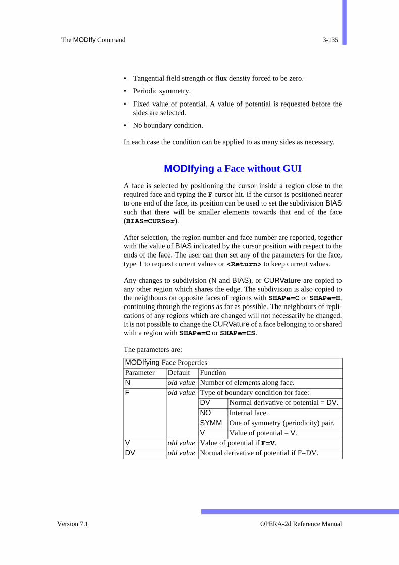
The MODIfy Command 3-135
the
ary.
ther
face
etherhe face,
ed to
epli-ged.
d
• Tangential field strength or flux density forced to be zero.
• Periodic symmetry.
• Fixed value of potential. A value of potential is requested before sides are selected.
• No boundary condition.
In each case the condition can be applied to as many sides as necess
MODIfying a Face without GUI
A face is selected by positioning the cursor inside a region close torequired face and typing the F cursor hit. If the cursor is positioned neareto one end of the face, its position can be used to set the subdivision BIASsuch that there will be smaller elements towards that end of the (BIAS=CURSor).
After selection, the region number and face number are reported, togwith the value of BIAS indicated by the cursor position with respect to tends of the face. The user can then set any of the parameters for thetype ! to request current values or <Return> to keep current values.
Any changes to subdivision (N and BIAS), or CURVature are copied toany other region which shares the edge. The subdivision is also copithe neighbours on opposite faces of regions with SHAPe=C or SHAPe=H,continuing through the regions as far as possible. The neighbours of rcations of any regions which are changed will not necessarily be chanIt is not possible to change the CURVature of a face belonging to or sharewith a region with SHAPe=C or SHAPe=CS.
The parameters are:
MODIfying Face Properties Parameter Default Function N old value Number of elements along face. F old value Type of boundary condition for face:
DV Normal derivative of potential = DV. NO Internal face. SYMM One of symmetry (periodicity) pair. V Value of potential = V.
V old value Value of potential if F=V. DV old value Normal derivative of potential if F=DV.
Version 7.1 OPERA-2d Reference Manual
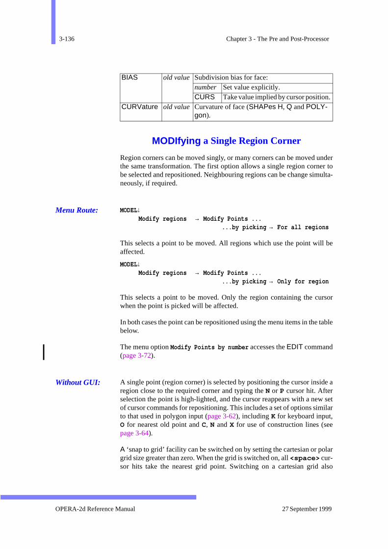
3-136 Chapter 3 - The Pre and Post-Processor
underr toulta-
l be
rsor
table
de a
w setilar
e
olar
also
MODIfying a Single Region Corner
Region corners can be moved singly, or many corners can be moved the same transformation. The first option allows a single region cornebe selected and repositioned. Neighbouring regions can be change simneously, if required.
Menu Route: MODEL↓Modify regions → Modify Points ...
...by picking → For all regions
This selects a point to be moved. All regions which use the point wilaffected.
MODEL↓Modify regions → Modify Points ...
...by picking → Only for region
This selects a point to be moved. Only the region containing the cuwhen the point is picked will be affected.
In both cases the point can be repositioned using the menu items in thebelow.
The menu option Modify Points by number accesses the EDIT command(page 3-72).
Without GUI: A single point (region corner) is selected by positioning the cursor insiregion close to the required corner and typing the N or P cursor hit. Afterselection the point is high-lighted, and the cursor reappears with a neof cursor commands for repositioning. This includes a set of options simto that used in polygon input (page 3-62), including K for keyboard input,O for nearest old point and C, N and X for use of construction lines (sepage 3-64).
A ‘snap to grid’ facility can be switched on by setting the cartesian or pgrid size greater than zero. When the grid is switched on, all <space> cur-sor hits take the nearest grid point. Switching on a cartesian grid
BIAS old value Subdivision bias for face: number Set value explicitly. CURS Take value implied by cursor position.
CURVature old value Curvature of face (SHAPes H, Q and POLY-gon).
OPERA-2d Reference Manual 27 September 1999
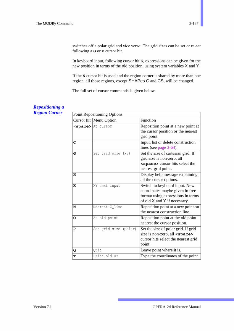
The MODIfy Command 3-137
et
e
one
switches off a polar grid and vice versa. The grid sizes can be set or re-sfollowing a G or P cursor hit.
In keyboard input, following cursor hit K, expressions can be given for thnew position in terms of the old position, using system variables X and Y.
If the N cursor hit is used and the region corner is shared by more thanregion, all those regions, except SHAPes C and CS, will be changed.
The full set of cursor commands is given below.
Repositioning a Region Corner
Point Repositioning Options Cursor hit Menu Option Function <space> At cursor Reposition point at a new point at
the cursor position or the nearest grid point.
C Input, list or delete construction lines (see page 3-64).
G Set grid size (xy) Set the size of cartesian grid. If grid size is non-zero, all <space> cursor hits select the nearest grid point.
H Display help message explaining all the cursor options.
K XY text input Switch to keyboard input. New coordinates maybe given in free format using expressions in termsof old X and Y if necessary.
N Nearest C_line Reposition point at a new point onthe nearest construction line.
O At old point Reposition point at the old point nearest the cursor position.
P Set grid size (polar) Set the size of polar grid. If grid size is non-zero, all <space> cursor hits select the nearest grid point.
Q Quit Leave point where it is. T Print old XY Type the coordinates of the point.
Version 7.1 OPERA-2d Reference Manual

3-138 Chapter 3 - The Pre and Post-Processor
posi-e old
of be
pplyam-
y.
ions.
lected
Transforming Many Region Corners
This option allows many region corners to be selected and then retioned using a transformation, which can be expressed in terms of thcoordinates.
Menu Route: MODEL↓Modify regions → Modify Points ...
... by picking → Transform many points
The program prompts for a expressions which define the new valuesXand Y in terms of their old values and the allows the transformation toapplied to as many points as necessary.
Without GUI: The transformation operation is selected with the T cursor hit (the positionof the cursor does not matter). The program prompts the user to suexpressions for the new coordinate positions in terms of the old. For exple, x+1 y+2 will move selected points by one unit in x and 2 units inThe user can then select as many region corners as required with A cursorhits. All regions shared by the points (except SHAPes C and CS) arechanged, and the display is immediately updated to show the new posit
MODIfying Region Properties
Menu Route: MODEL↓Modify regions → Modify Region → Pick Region
After selecting a region the appropriate group of parameters can be seand modified.
Without GUI: A region is selected by positioning the cursor inside it and typing the R cur-
X At intersection Reposition point at a new point atthe closest construction line inter-section or end.
Z Zoom display Execute the ZOOM (see page 3-183) command to change size of the picture.
Point Repositioning Options Cursor hit Menu Option Function
OPERA-2d Reference Manual 27 September 1999

The MODIfy Command 3-139
the
com-
-or the
- (see
sor hit. After selection the region is high-lighted. Any parameter of region can then be reset.
The parameters are divided into groups, each group having a sub-mand: REGIon for region properties, COORdinates for coordinates,FACE for face properties, and LOCAl for local coordinates and replications. The default values of each parameters are the current values fregion selected. Only the region selected is modified.
The coordinates and face properties of POLYgons can not be changed inthis way. Their coordinates can only be modified with cursor hit N and theirface properties with cursor hit F.
The system variable AREA, the total area of the region including replications, can also be included in expressions for numeric parameterspage 3-15).
The sub-commands and their parameters are:
The parameters are fully described under the DRAW command, page 3-43.
Region MODIfying Sub-Commands Sub-Command Function and Parameters COORdinates Coordinates of SHAPEs C and CS
R12, R34, P14, P23, P1, P2, P3, P4 COORdinates Coordinates of SHAPEs H and Q
X12, X34, Y14, Y23, X1, Y1, X2, Y2, X3, Y3, X4, Y4 FACE Face properties (not SHAPe=POLYgon or SHAPe-
BACKground ) F1, F2, F3, F4, V1, V2, V3, V4, DV1, DV2, DV3,DV4, N1, N2,N3, N4, B1, B2, B3, B4, P1, P2, P3,P4
LOCAl Local Coordinates and replications XCENtre, YCENtre, ANGLe, NX, NY, DX, DY, MIR-Ror, TMIRror, ROT, TROT
QUIT Finish MODIfying this region. REGIon Region properties
SHAPe (not available for polygons), MATErial,PERM, DENSity, SIGMa, PHASe, N, SYMMetry,VELOcity
Version 7.1 OPERA-2d Reference Manual
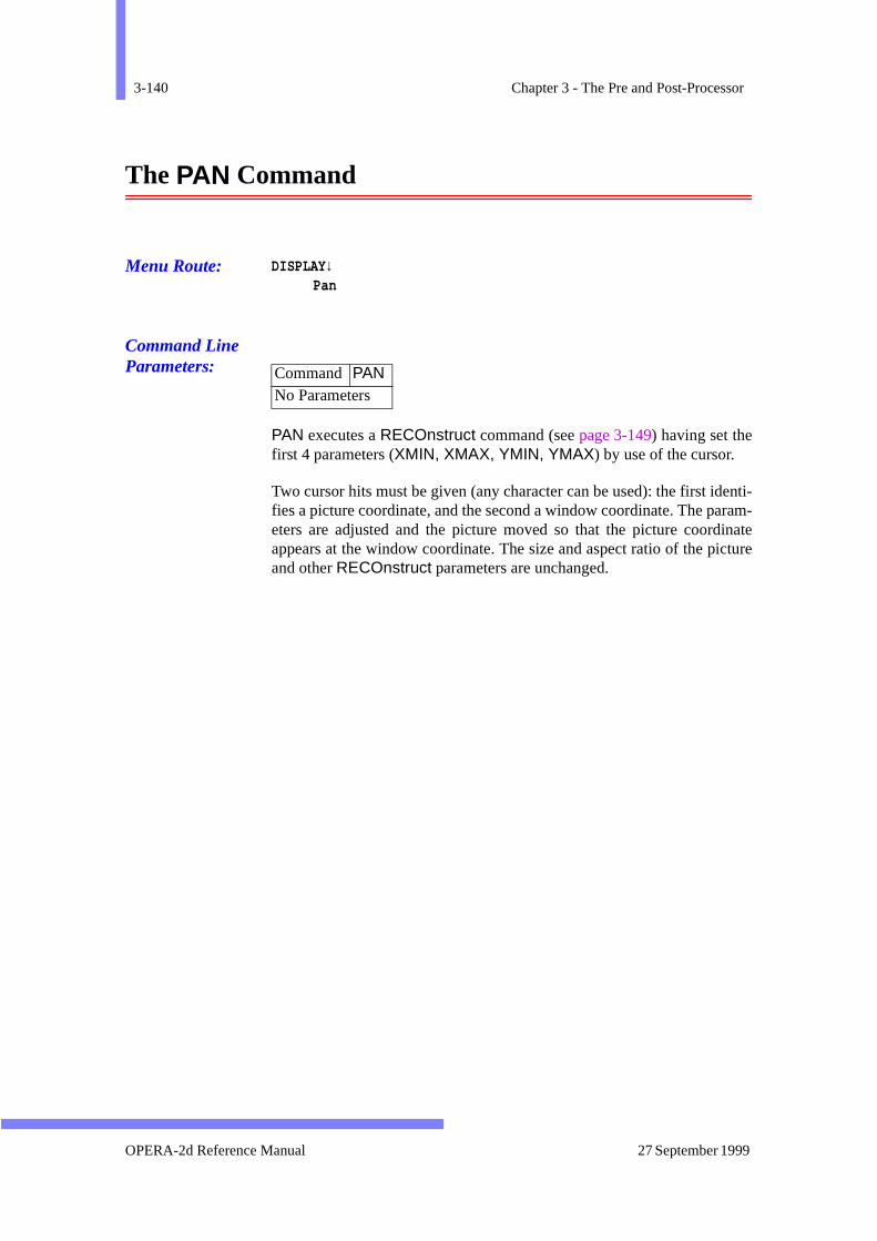
3-140 Chapter 3 - The Pre and Post-Processor
enti-ram-inate
icture
The PAN Command
Menu Route: DISPLAY↓Pan
Command Line Parameters:
PAN executes a RECOnstruct command (see page 3-149) having set thefirst 4 parameters (XMIN, XMAX, YMIN, YMAX) by use of the cursor.
Two cursor hits must be given (any character can be used): the first idfies a picture coordinate, and the second a window coordinate. The paeters are adjusted and the picture moved so that the picture coordappears at the window coordinate. The size and aspect ratio of the pand other RECOnstruct parameters are unchanged.
Command PAN No Parameters
OPERA-2d Reference Manual 27 September 1999

The PLOT Command 3-141
The PLOT Command
Menu Route: FIELDS↓Graphs → Along region sides line
Command Line Parameters:
Command PLOTParameter Default Function NEW YES New graphs switch:
NO Use the points from the last CIRCle, PLOT or LINE command.
YES Create a new line from region sides.CURVature 0 Curvature of line. COMPonent POT Expression of field components. TIME 0 For Steady-state ac solutions only: time at
which basic field quantities are evaluated. number Angle in degrees around ac cycle. AMPL Amplitude. PHAS Phase angle. TAVE Time average.
AVERage YES Nodally averaged fields switch: NO Use shape function derivative fields.YES Use nodally averaged field.
GRAPh YES Graph display switch: NO No graph. YES Values displayed as graph.
PRINt NO Printed values switch: NO Values printed to file opera2.lp. YES Values printed to screen and file
opera2.lp. AUTOmatic YES Automatic graph scale switch:
NO Vertical axis limits set by VMIN and VMAX.
YES Vertical axis set automatically. VMAX none Upper limit of vertical axis of graph AUTO-
matic=NO. VMIN none Lower limit of vertical axis of graph AUTO-
matic=NO.
Version 7.1 OPERA-2d Reference Manual
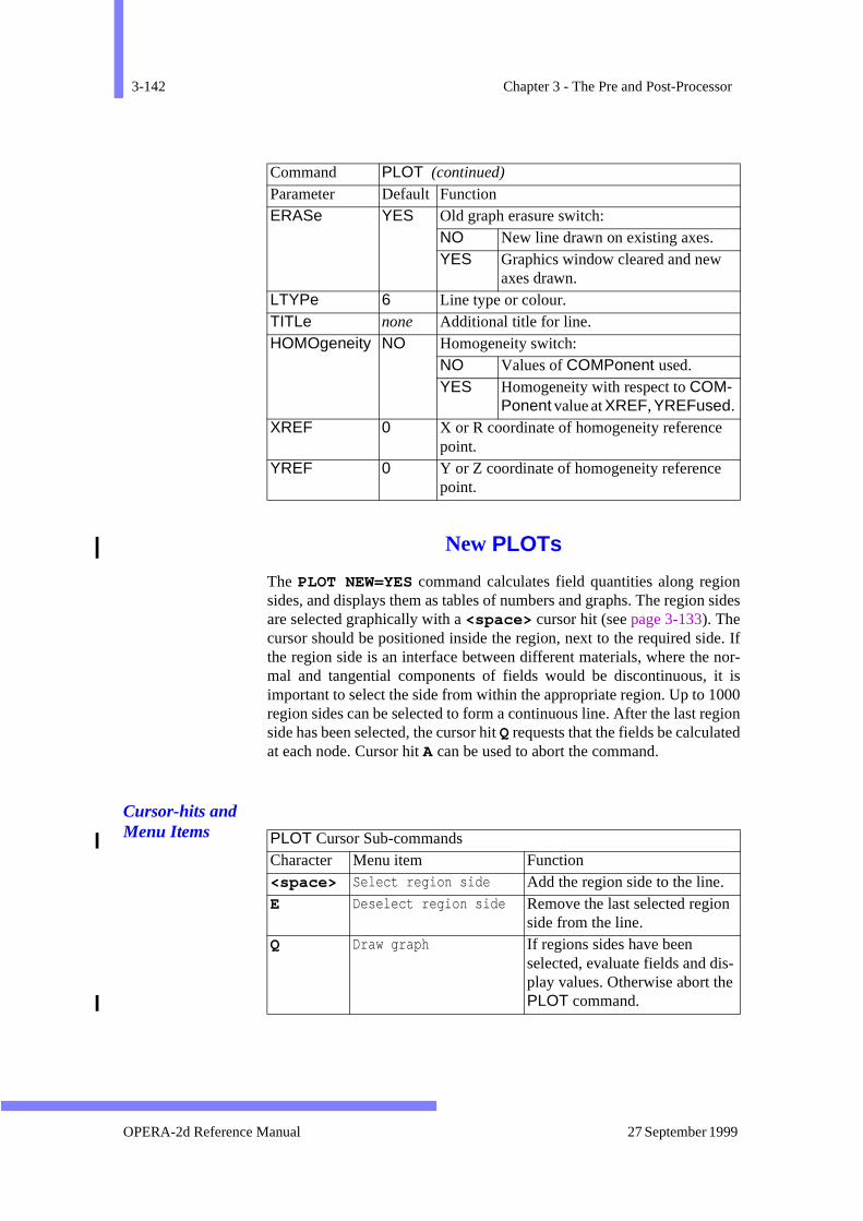
3-142 Chapter 3 - The Pre and Post-Processor
on sides
e. If nor-it is000giond
New PLOTs
The PLOT NEW=YES command calculates field quantities along regisides, and displays them as tables of numbers and graphs. The regionare selected graphically with a <space> cursor hit (see page 3-133). Thecursor should be positioned inside the region, next to the required sidthe region side is an interface between different materials, where themal and tangential components of fields would be discontinuous, important to select the side from within the appropriate region. Up to 1region sides can be selected to form a continuous line. After the last reside has been selected, the cursor hit Q requests that the fields be calculateat each node. Cursor hit A can be used to abort the command.
Cursor-hits and Menu Items
ERASe YES Old graph erasure switch: NO New line drawn on existing axes. YES Graphics window cleared and new
axes drawn. LTYPe 6 Line type or colour. TITLe none Additional title for line. HOMOgeneity NO Homogeneity switch:
NO Values of COMPonent used. YES Homogeneity with respect to COM-
Ponent value at XREF, YREFused. XREF 0 X or R coordinate of homogeneity reference
point. YREF 0 Y or Z coordinate of homogeneity reference
point.
Command PLOT (continued)
Parameter Default Function
PLOT Cursor Sub-commandsCharacter Menu item Function <space> Select region side Add the region side to the line. E Deselect region side Remove the last selected region
side from the line. Q Draw graph If regions sides have been
selected, evaluate fields and dis-play values. Otherwise abort thePLOT command.
OPERA-2d Reference Manual 27 September 1999
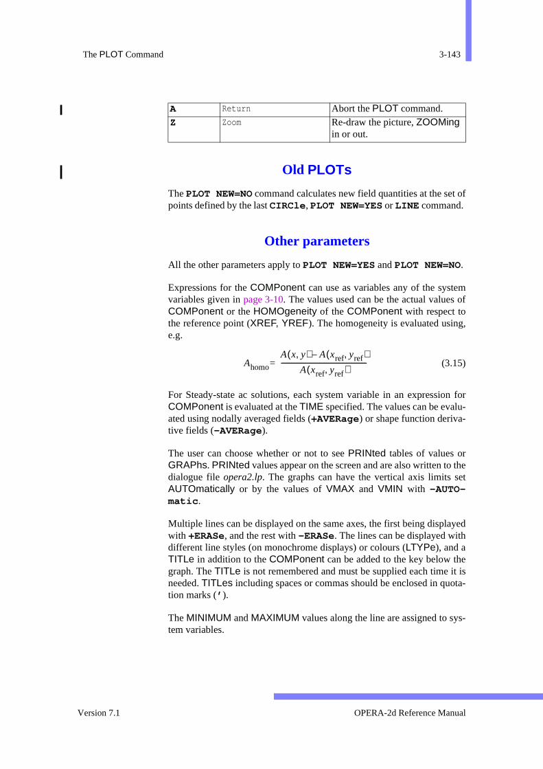
The PLOT Command 3-143
t of
m of
g,
n for-
theet
ayed
eit isota-
s-
Old PLOTs
The PLOT NEW=NO command calculates new field quantities at the sepoints defined by the last CIRCle , PLOT NEW=YES or LINE command.
Other parameters
All the other parameters apply to PLOT NEW=YES and PLOT NEW=NO.
Expressions for the COMPonent can use as variables any of the systevariables given in page 3-10. The values used can be the actual valuesCOMPonent or the HOMOgeneity of the COMPonent with respect tothe reference point (XREF, YREF). The homogeneity is evaluated usine.g.
(3.15)
For Steady-state ac solutions, each system variable in an expressioCOMPonent is evaluated at the TIME specified. The values can be evaluated using nodally averaged fields (+AVERage) or shape function deriva-tive fields (-AVERage).
The user can choose whether or not to see PRINted tables of values orGRAPhs. PRINted values appear on the screen and are also written todialogue file opera2.lp. The graphs can have the vertical axis limits sAUTOmatically or by the values of VMAX and VMIN with -AUTO-matic .
Multiple lines can be displayed on the same axes, the first being displwith +ERASe, and the rest with -ERASe. The lines can be displayed withdifferent line styles (on monochrome displays) or colours (LTYPe), and aTITLe in addition to the COMPonent can be added to the key below thgraph. The TITLe is not remembered and must be supplied each time needed. TITLes including spaces or commas should be enclosed in qution marks (’ ).
The MINIMUM and MAXIMUM values along the line are assigned to sytem variables.
A Return Abort the PLOT command. Z Zoom Re-draw the picture, ZOOMing
in or out.
Ahomo
A x y,( ) A xref yref,( )–
A xref yref,( )---------------------------------------------------=
Version 7.1 OPERA-2d Reference Manual
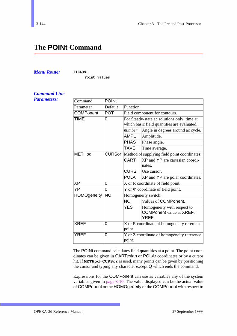
3-144 Chapter 3 - The Pre and Post-Processor
or-rng
mue
The POINt Command
Menu Route: FIELDS↓Point values
Command Line Parameters:
The POINt command calculates field quantities at a point. The point codinates can be given in CARTesian or POLAr coordinates or by a cursohit. If METHod=CURSor is used, many points can be given by positionithe cursor and typing any character except Q which ends the command.
Expressions for the COMPonent can use as variables any of the systevariables given in page 3-10. The value displayed can be the actual valof COMPonent or the HOMOgeneity of the COMPonent with respect to
Command POINt Parameter Default Function COMPonent POT Field component for contours. TIME 0 For Steady-state ac solutions only: time at
which basic field quantities are evaluated. number Angle in degrees around ac cycle.AMPL Amplitude. PHAS Phase angle. TAVE Time average.
METHod CURSor Method of supplying field point coordinates:CART XP and YP are cartesian coordi-
nates. CURS Use cursor. POLA XP and YP are polar coordinates.
XP 0 X or R coordinate of field point. YP 0 Y or Φ coordinate of field point. HOMOgeneity NO Homogeneity switch:
NO Values of COMPonent. YES Homogeneity with respect to
COMPonent value at XREF, YREF.
XREF 0 X or R coordinate of homogeneity referencepoint.
YREF 0 Y or Z coordinate of homogeneity referencepoint.
OPERA-2d Reference Manual 27 September 1999
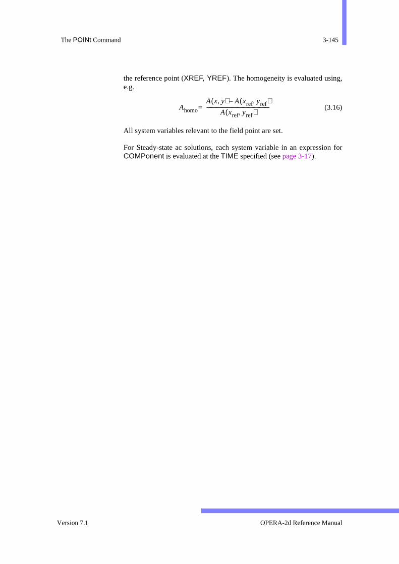
The POINt Command 3-145
g,
n for
the reference point (XREF, YREF). The homogeneity is evaluated usine.g.
(3.16)
All system variables relevant to the field point are set.
For Steady-state ac solutions, each system variable in an expressioCOMPonent is evaluated at the TIME specified (see page 3-17).
Ahomo
A x y,( ) A xref yref,( )–
A xref yref,( )---------------------------------------------------=
Version 7.1 OPERA-2d Reference Manual
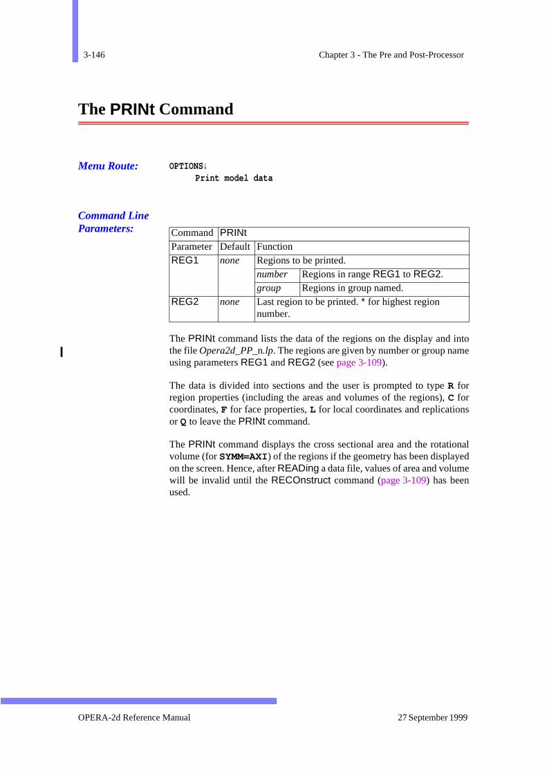
3-146 Chapter 3 - The Pre and Post-Processor
intoe
s
ionalede
The PRINt Command
Menu Route: OPTIONS↓Print model data
Command Line Parameters:
The PRINt command lists the data of the regions on the display and the file Opera2d_PP_n.lp. The regions are given by number or group namusing parameters REG1 and REG2 (see page 3-109).
The data is divided into sections and the user is prompted to type R forregion properties (including the areas and volumes of the regions), C forcoordinates, F for face properties, L for local coordinates and replicationor Q to leave the PRINt command.
The PRINt command displays the cross sectional area and the rotatvolume (for SYMM=AXI) of the regions if the geometry has been displayon the screen. Hence, after READing a data file, values of area and volumwill be invalid until the RECOnstruct command (page 3-109) has beenused.
Command PRINt Parameter Default Function REG1 none Regions to be printed.
number Regions in range REG1 to REG2. group Regions in group named.
REG2 none Last region to be printed. * for highest region number.
OPERA-2d Reference Manual 27 September 1999
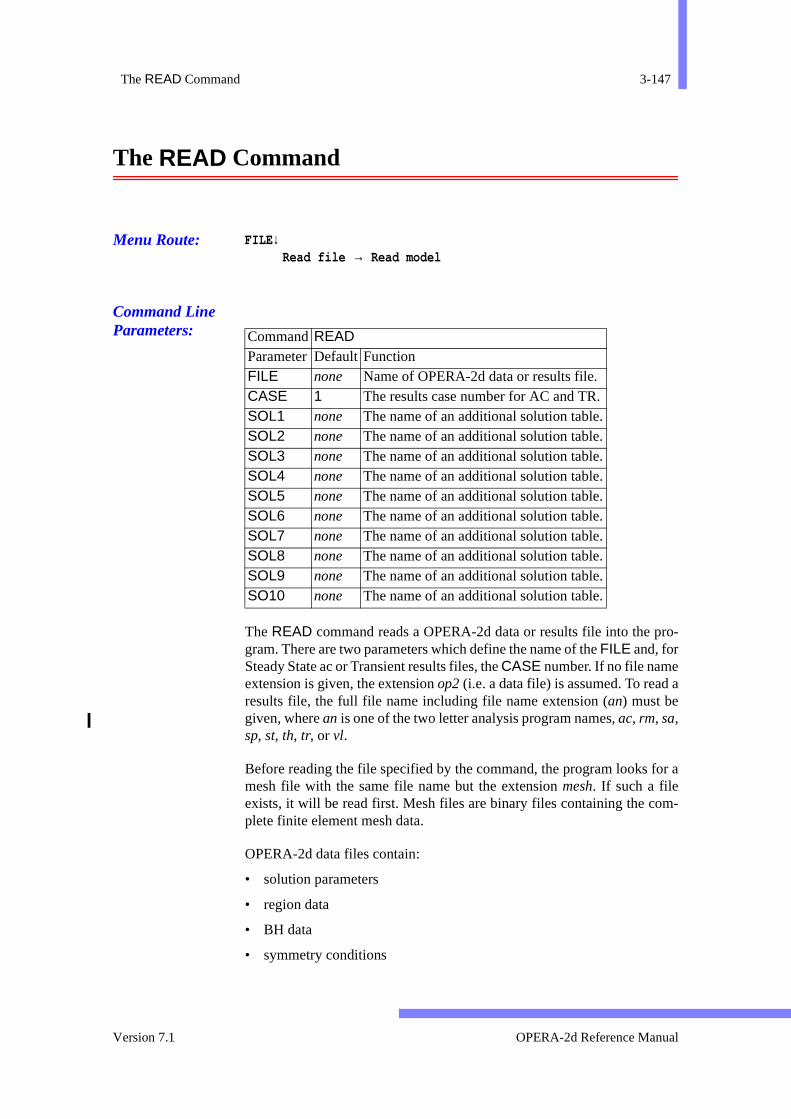
The READ Command 3-147
ro-
a
for a
m-
The READ Command
Menu Route: FILE ↓Read file → Read model
Command Line Parameters:
The READ command reads a OPERA-2d data or results file into the pgram. There are two parameters which define the name of the FILE and, forSteady State ac or Transient results files, the CASE number. If no file nameextension is given, the extension op2 (i.e. a data file) is assumed. To readresults file, the full file name including file name extension (an) must begiven, where an is one of the two letter analysis program names, ac, rm, sa,sp, st, th, tr, or vl.
Before reading the file specified by the command, the program looks mesh file with the same file name but the extension mesh. If such a fileexists, it will be read first. Mesh files are binary files containing the coplete finite element mesh data.
OPERA-2d data files contain:
• solution parameters
• region data
• BH data
• symmetry conditions
CommandREADParameterDefault FunctionFILE none Name of OPERA-2d data or results file.CASE 1 The results case number for AC and TR.SOL1 none The name of an additional solution table.SOL2 none The name of an additional solution table.SOL3 none The name of an additional solution table.SOL4 none The name of an additional solution table.SOL5 none The name of an additional solution table.SOL6 none The name of an additional solution table.SOL7 none The name of an additional solution table.SOL8 none The name of an additional solution table.SOL9 none The name of an additional solution table.SO10 none The name of an additional solution table.
Version 7.1 OPERA-2d Reference Manual

3-148 Chapter 3 - The Pre and Post-Processor
ent/l the dur-
ppliedbles.heirtheinfor-
• data set by the EXTRa command including the current units set
• region groups
Results file also contain this data with the solution potentials, currcharge densities and permeabilities/permittivities appended. Thus aldata necessary for adjusting the specification of a problem is availableing a post-processing session.
The stress, thermal and space charge beam analysis program are suwith data and can return solutions to the pre and post-processor in taUp to 10 tables can be loaded from a data or results file by giving tnames to parameters SOLn. The values in tables can be accessed by post-processing commands by their system variable names. For more mation about tables, see page 3-103.
OPERA-2d Reference Manual 27 September 1999
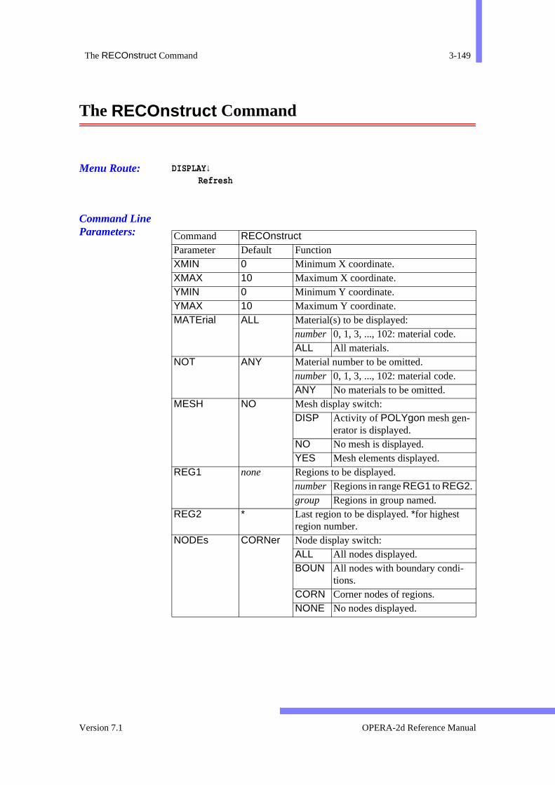
The RECOnstruct Command 3-149
The RECOnstruct Command
Menu Route: DISPLAY↓Refresh
Command Line Parameters:
Command RECOnstructParameter Default Function XMIN 0 Minimum X coordinate. XMAX 10 Maximum X coordinate. YMIN 0 Minimum Y coordinate. YMAX 10 Maximum Y coordinate. MATErial ALL Material(s) to be displayed:
number 0, 1, 3, ..., 102: material code. ALL All materials.
NOT ANY Material number to be omitted. number 0, 1, 3, ..., 102: material code. ANY No materials to be omitted.
MESH NO Mesh display switch: DISP Activity of POLYgon mesh gen-
erator is displayed. NO No mesh is displayed. YES Mesh elements displayed.
REG1 none Regions to be displayed. number Regions in range REG1 to REG2. group Regions in group named.
REG2 * Last region to be displayed. *for highest region number.
NODEs CORNer Node display switch: ALL All nodes displayed. BOUN All nodes with boundary condi-
tions. CORN Corner nodes of regions. NONE No nodes displayed.
Version 7.1 OPERA-2d Reference Manual

3-150 Chapter 3 - The Pre and Post-Processor
e- and
that
The RECOnstruct command displays pictures of the model. The paramters allow the scaling of the picture to the graphics window to be setthe type of picture to be set in various ways.
Picture Coordinates
The first four parameters (XMIN, XMAX, YMIN, YMAX) set the coordi-nate limits of the picture. If XMAX–XMIN≈YMAX–YMIN, then the value ofXMAX is adjusted to match the aspect ratio of the graphics display so
FILL MATErials Colour fill switch: BOUN Line display of material outlines. ELEM Elements filled with material col-
our and MATErial outlines drawn. ERRO Redraw the MESH command
error check display. NO Line display of regions. MATE Regions filled with material col-
our and MATErial outlines drawn. REGI Regions filled with material col-
our and REGIon outlines drawn. YES Regions filled with material col-
our with no outlines. LABEl YES Region numbering switch:
NO No labels. YES Regions labelled with region num-
bers. AXES YES Axes display switch:
NO No axes. REDR Axes re-drawn after regions. YES Axes displayed once.
ERASe YES Picture erase switch: NO Old picture not erased. YES Old picture erased.
CLINe YES Construction line switch: NO Construction lines not displayed. YES Construction lines displayed.
BACKground YES Background region switch: NO Background region not displayed.YES Background region displayed.
Command RECOnstruct (continued)
Parameter Default Function
OPERA-2d Reference Manual 27 September 1999
The RECOnstruct Command 3-151
g
yed.
his
:
uiv-
.
the
-
f
esh
sith
circles will appear round.
If XMAX≤XMIN or YMAX≤YMIN, the program calculates the boundinrectangle which fits the selected regions and displays within that.
These parameters can also be set by the PAN and ZOOM commands(page 3-140 and page 3-183).
Regions and Materials
There are four parameters which control which regions are displaREG1 and REG2 set a range of region numbers. MATErial sets a materialnumber, the only material to be displayed, or ALL for all materials. NOTsets the number of a material to be omitted from the display, or ANY for noomissions.
Alternatively, REG1 can be used to specify a region group name. In tcase REG2, MATErial and NOT are ignored (see page 3-109).
Picture Style
The style of the picture is set by the FILL parameter, using the Menu Route
Menu Route: DISPLAY↓Style
The following options are available in the sub-menu. The keyboard eqalents are also listed.
• Line drawing or -FILL gives a line drawing of all region boundaries
• Material boundary or FILL=BOUNdaries gives a line drawing ofthe material boundaries. This is only possible if the mesh exists. Ifmesh does not exist, FILL=BOUNdaries is the same as -FILL .
• Fill (no outlines) or +FILL gives filled areas (on a suitable graphics device). Other FILL options specify how filled areas are outlined.
• Fill regions or FILL=REGIon gives filled areas with the outline oeach region displayed as well.
• Fill materials or FILL=MATErials also gives filled areas, withthe outline of the materials displayed. This is only possible if the mexists. If the mesh does not exist, FILL=MATErials is the same asFILL=REGIons .
• Fill elements or FILL=ELEMents has the same effect aFILL=MATErials but since each element is filled, it can cope w
Version 7.1 OPERA-2d Reference Manual
3-152 Chapter 3 - The Pre and Post-Processor
, forion
,
e
ld
ents- withvity
h asee
meshes produced by the adaptive analysis programs, in whichcurved sided regions, the elements might not fit the original regshape.
• Mesh error check or FILL=ERROr redisplays the error check displaywhich is given by the MESH command (see page 3-128).
Labels, Construction Lines and Axes
Region number LABEls can be switched on or off with ±LABEl , the con-struction lines used in DRAW SHAPe=POLYgon or MODIfy with±CLINe (see page 3-64 and page 3-130) and the background region with±BACKground . With FILLed displays, the axes are obliterated by thregions. They can be re-displayed after the regions with AXES=REDRaw.Additional RECOnstruct commands can be given without clearing the opicture first with –ERASe.
Nodes and Elements
The finite element mesh can be displayed over the regions. The elemcan be displayed at any time with +MESH. However, the mesh of a background region can only be displayed if the mesh has been generatedthe MESH command. If the mesh is generated for the display, the actiof the POLYgonal mesh generator can be shown with MESH=DISPlay.
CORNer nodes (i.e. the defining points) of regions, and nodes witBOUNdary condition can be displayed at any time. If the mesh exists (page 3-128) ALL the NODEs can be displayed. NODEs=NONE preventseven the corner nodes from being displayed.
OPERA-2d Reference Manual 27 September 1999
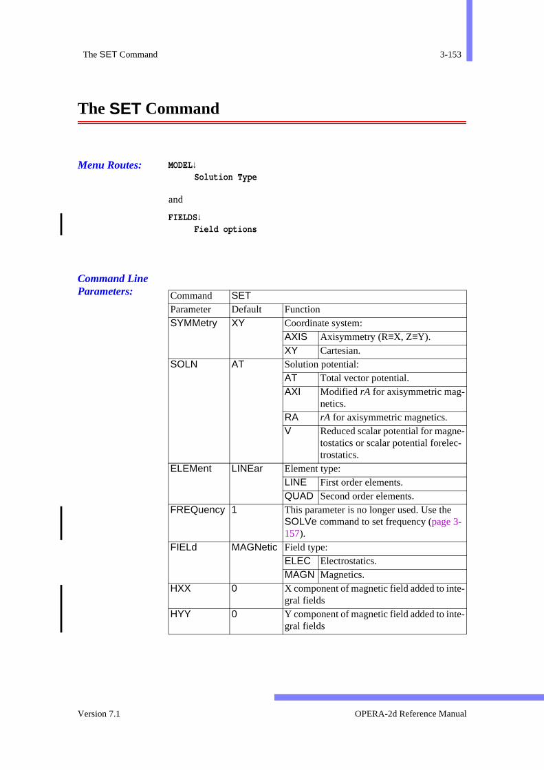
The SET Command 3-153
-
-
-
The SET Command
Menu Routes: MODEL↓Solution Type
and
FIELDS↓Field options
Command Line Parameters:
Command SET Parameter Default Function SYMMetry XY Coordinate system:
AXIS Axisymmetry (R≡X, Z≡Y). XY Cartesian.
SOLN AT Solution potential: AT Total vector potential. AXI Modified rA for axisymmetric mag-
netics. RA rA for axisymmetric magnetics. V Reduced scalar potential for magne
tostatics or scalar potential forelec-trostatics.
ELEMent LINEar Element type: LINE First order elements. QUAD Second order elements.
FREQuency 1 This parameter is no longer used. Use the SOLVe command to set frequency (page 3-157).
FIELd MAGNetic Field type: ELEC Electrostatics. MAGN Magnetics.
HXX 0 X component of magnetic field added to integral fields
HYY 0 Y component of magnetic field added to integral fields
Version 7.1 OPERA-2d Reference Manual
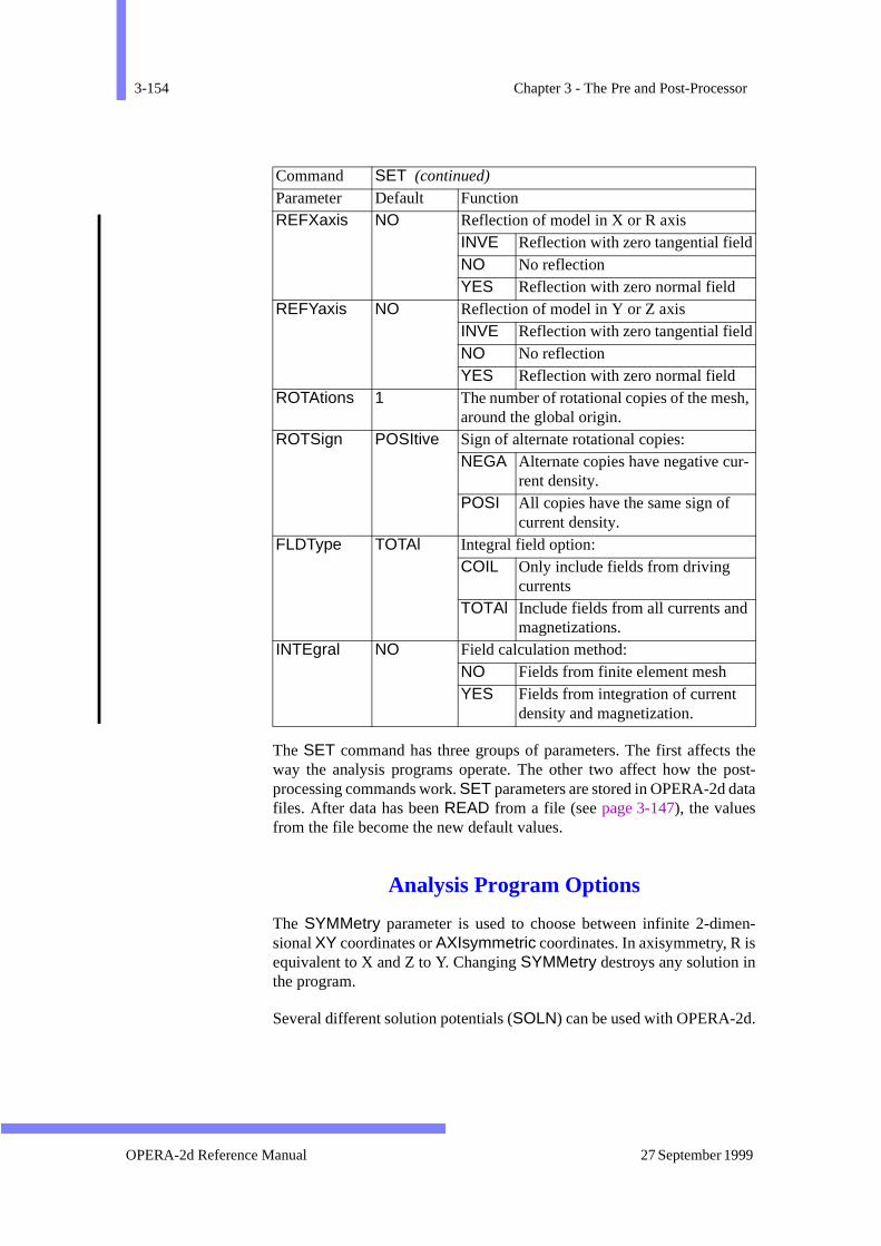
3-154 Chapter 3 - The Pre and Post-Processor
theost-ta
en-
.
,
The SET command has three groups of parameters. The first affectsway the analysis programs operate. The other two affect how the pprocessing commands work. SET parameters are stored in OPERA-2d dafiles. After data has been READ from a file (see page 3-147), the valuesfrom the file become the new default values.
Analysis Program Options
The SYMMetry parameter is used to choose between infinite 2-dimsional XY coordinates or AXIsymmetric coordinates. In axisymmetry, R isequivalent to X and Z to Y. Changing SYMMetry destroys any solution inthe program.
Several different solution potentials (SOLN) can be used with OPERA-2d
REFXaxis NO Reflection of model in X or R axisINVE Reflection with zero tangential fieldNO No reflectionYES Reflection with zero normal field
REFYaxis NO Reflection of model in Y or Z axisINVE Reflection with zero tangential fieldNO No reflectionYES Reflection with zero normal field
ROTAtions 1 The number of rotational copies of the mesharound the global origin.
ROTSign POSItive Sign of alternate rotational copies:NEGA Alternate copies have negative cur-
rent density.POSI All copies have the same sign of
current density.FLDType TOTAl Integral field option:
COIL Only include fields from driving currents
TOTAl Include fields from all currents and magnetizations.
INTEgral NO Field calculation method:NO Fields from finite element meshYES Fields from integration of current
density and magnetization.
Command SET (continued) Parameter Default Function
OPERA-2d Reference Manual 27 September 1999
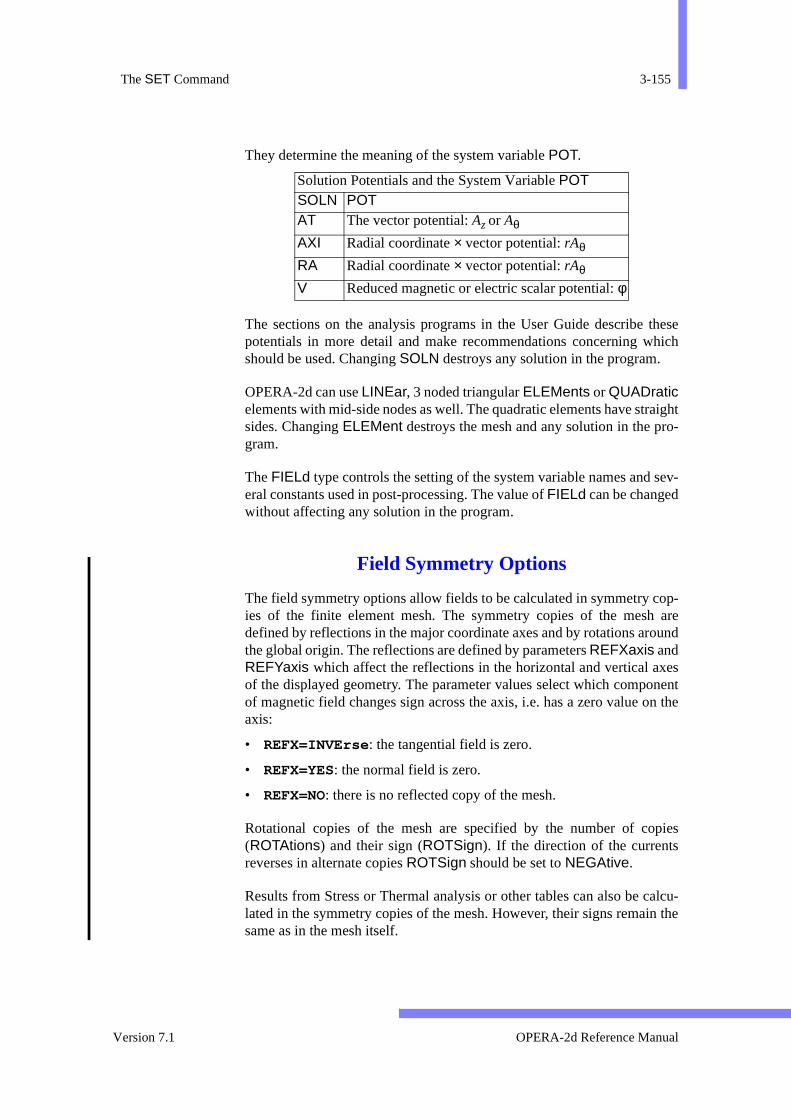
The SET Command 3-155
thesehich
aightro-
sev-
op- areound
esnentn the
pies
alcu-n the
They determine the meaning of the system variable POT.
The sections on the analysis programs in the User Guide describe potentials in more detail and make recommendations concerning wshould be used. Changing SOLN destroys any solution in the program.
OPERA-2d can use LINEar, 3 noded triangular ELEMents or QUADraticelements with mid-side nodes as well. The quadratic elements have strsides. Changing ELEMent destroys the mesh and any solution in the pgram.
The FIELd type controls the setting of the system variable names and eral constants used in post-processing. The value of FIELd can be changedwithout affecting any solution in the program.
Field Symmetry Options
The field symmetry options allow fields to be calculated in symmetry cies of the finite element mesh. The symmetry copies of the meshdefined by reflections in the major coordinate axes and by rotations arthe global origin. The reflections are defined by parameters REFXaxis andREFYaxis which affect the reflections in the horizontal and vertical axof the displayed geometry. The parameter values select which compoof magnetic field changes sign across the axis, i.e. has a zero value oaxis:
• REFX=INVErse : the tangential field is zero.
• REFX=YES: the normal field is zero.
• REFX=NO: there is no reflected copy of the mesh.
Rotational copies of the mesh are specified by the number of co(ROTAtions) and their sign (ROTSign). If the direction of the currentsreverses in alternate copies ROTSign should be set to NEGAtive.
Results from Stress or Thermal analysis or other tables can also be clated in the symmetry copies of the mesh. However, their signs remaisame as in the mesh itself.
Solution Potentials and the System Variable POT SOLN POTAT The vector potential: Az or Aθ
AXI Radial coordinate × vector potential: rAθ
RA Radial coordinate × vector potential: rAθ
V Reduced magnetic or electric scalar potential: φ
Version 7.1 OPERA-2d Reference Manual
3-156 Chapter 3 - The Pre and Post-Processor
-ele-g theach
inte-ying
etry
eldated
itiesected
Integral Field Options
By default, the electromagnetic fields (B and H) are calculated by the postprocessing routines by interpolation of nodal values, using the finite ment shape functions. These nodal values are calculated by averaginappropriate derivatives of potential from the elements surrounding enode.
Electromagnetic fields can be also calculated at any point in space bygration of the current densities and magnetizations in the current carrand permeable elements of the mesh. This is selected using
SET +INTEgral, FLDType=TOTAl
In order to obtain the correct values it is necessary to specify the symmcopies of the mesh using the parameters REFXaxis, REFYaxis, ROTA-tions and ROTSign, page 3-155.
If the finite element solution includes the effect of a uniform external fiimplied by the boundary conditions, this can be added to the calculfield by setting non-zero values to HXX and HYY as appropriate.
It is also possible to calculate the fields from the specified current densin the mesh, ignoring induced currents and magnetizations. This is selusing FLDType=COILonly .
Only B and H are calculated by integration. When +INTEgral isselected, other field quantities are calculated by interpolation.
OPERA-2d Reference Manual 27 September 1999

The SOLVe Command 3-157
od-andlver
and,
put
is
n-
The SOLVe Command
Menu Route: FILE ↓Write file → Analysis data
Command line Parameters:
The SOLVe command has a single parameter for the type of analysis mule that is to be used for calculation of the field solution. This commmust be executed before writing the analysis file, and the correct soTYPE must be specified.
Other options are available as sub-commands within the solve commallowing various parameters to be set for the analysis program.
Command SOLVE Parameter Default Function TYPE none Module to be used for the analysis of the model
ST Static analysisAC Steady-state AC analysisTR Transient time varying analysisVL Velocity analysisSA Stress analysisTH Thermal analysisTHTR Thermal transient analysisSP Space charge analysisRM Rotating Machine analysis
SOLVe Keyboard Sub-commandsSub-command Function CASE Give case data, either scale factors, frequencies or out
times, for the analysis programDATA Give data specific to the options available in the analys
programsDRIVe Select the drive functions to be used by the drives in tra
sient and rotating machine analysis QUIT Quit the SOLVe command
Version 7.1 OPERA-2d Reference Manual

3-158 Chapter 3 - The Pre and Post-Processor
d in avail-
aluecom-
eri-licate willlved
sis
s
n
-
CASE Sub-command
The case sub-command allows multiple cases to be set up and solvesingle analysis file. The different modules have different case types aable.
The solution file can contain multiple solutions (one for each case vset) that can be read in by setting the CASE parameter of the READ mand.
Command line Parameters:
For output times (TR and RM), all values in the list are ordered in numcal order, so inserting and adding may have the same effect. Any dupvalues are removed from the list. If adaption is being used, the adaptionhappen on the first case in the list only. All subsequent cases will be sousing this mesh.
Modules Case typeST/VL/SP Scale factor used to multiply all drive sources (current
density, non-zero potential boundaries)AC Frequencies for which the steady state harmonic analy
will be runTR/RM/THTR Output times at which a solution will be storedSA/TH Multiple cases are not available
Sub-commandCASEParameter Default DescriptionCOMMand ADD Command option for generating the list of case
ADD Adds a new case value to the end ofthe list of cases
INSErt Inserts a new case at the position given
REPLace Replaces the case value at the positiogiven
DELEte Deletes the case value form the position specified
LIST Lists the current case listPOSItion none Sets the position in the case list for inserting,
replacing or deleting valuesVALUe none Sets the value for adding, inserting or replacing
OPERA-2d Reference Manual 27 September 1999
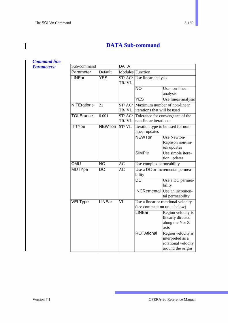
The SOLVe Command 3-159
DATA Sub-command
Command line Parameters: Sub-command DATA
Parameter Default ModulesFunctionLINEar YES ST/ AC/
TR/ VLUse linear analysis
NO Use non-linear analysis
YES Use linear analysisNITErations 21 ST/ AC/
TR/ VLMaximum number of non-linear iterations that will be used
TOLErance 0.001 ST/ AC/ TR/ VL
Tolerance for convergence of the non-linear iterations
ITTYpe NEWTon ST/ VL Iteration type to be used for non-linear updatesNEWTon Use Newton-
Raphson non-lin-ear updates
SIMPle Use simple itera-tion updates
CMU NO AC Use complex permeability MUTYpe DC AC Use a DC or Incremental permea-
bilityDC Use a DC permea-
bilityINCRemental Use an incremen-
tal permeabilityVELType LINEar VL Use a linear or rotational velocity
(see comment on units below)LINEar Region velocity is
linearly directed along the Yor Z axis
ROTAtional Region velocity is interpreted as a rotational velocity around the origin
Version 7.1 OPERA-2d Reference Manual
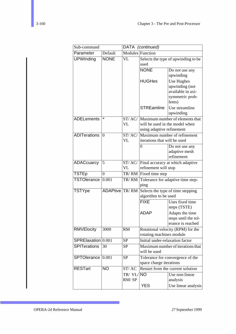
3-160 Chapter 3 - The Pre and Post-Processor
UPWInding NONE VL Selects the type of upwinding to beusedNONE Do not use any
upwindingHUGHes Use Hughes
upwinding (not available in axi-symmetric prob-lems)
STREamline Use streamline upwinding
ADELements * ST/ AC/ VL
Maximum number of elements thatwill be used in the model when using adaptive refinement
ADITerations 0 ST/ AC/ VL
Maximum number of refinement iterations that will be used0 Do not use any
adaptive mesh refinement
ADACcuarcy 5 ST/ AC/ VL
Final accuracy at which adaptive refinement will stop
TSTEp 0 TR/ RM Fixed time stepTSTOlerance 0.001 TR/ RM Tolerance for adaptive time step-
pingTSTYpe ADAPtive TR/ RM Selects the type of time stepping
algorithm to be usedFIXE Uses fixed time
steps (TSTE)ADAP Adapts the time
steps until the tol-erance is reached
RMVElocity 3000 RM Rotational velocity (RPM) for the rotating machines module
SPRElaxation 0.001 SP Initial under-relaxation factor SPITerations 30 SP Maximum number of iterations that
will be usedSPTOlerance 0.001 SP Tolerance for convergence of the
space charge iterationsRESTart NO ST/ AC Restart from the current solution
TR/ VL/RM/ SP
NO Use non-linear analysis
YES Use linear analysis
Sub-command DATA (continued)Parameter Default ModulesFunction
OPERA-2d Reference Manual 27 September 1999

The SOLVe Command 3-161
y the ding
ingtions
o
The data sub-command can be used to specify any options required bchosen analysis program. The options that must be set will vary depenupon the analysis program.
DRIVe Sub-command
The DRIVe sub-command is for use only with the transient and rotatmachine analysis module, and can be used to set the list of drive funcapplied to the current sources and non-zero potential boundaries.
Command line Parameters:
SATYpe STREss SA Selects the type of stress analysis tbe usedSTREss Use plain stressSTRAin Use plain strainAXISymmetry Use axisymmetric
stratified
Sub-command DATA (continued)Parameter Default ModulesFunction
Sub-CommandDRIVeParameter Default DescriptionNUMBer none Number of the drive function to be set
LIST Option to output the list of drive numbers that can be set
Version 7.1 OPERA-2d Reference Manual
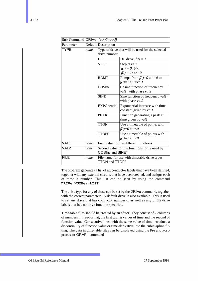
3-162 Chapter 3 - The Pre and Post-Processor
fined, eachand
seddrive
mnsd ofce ait-Post-
The program generates a list of all conductor labels that have been detogether with any external circuits that have been created, and assignsof these a number. This list can be seen by using the commDRIVe NUMBer=LIST
The drive type for any of these can be set by the DRIVe command, togetherwith the correct parameters. A default drive is also available. This is uto set any drive that has conductor number 0, as well as any of the labels that has no drive function specified.
Time-table files should be created by an editor. They consist of 2 coluof numbers in free-format, the first giving values of time and the seconfunction value. Consecutive lines with the same value of time introdudiscontinuity of function value or time-derivative into the cubic-spline fting. The data in time-table files can be displayed using the Pre and processor GRAPh command
TYPE none Type of drive that will be used for the selected drive numberDC DC drive, f(t) = 1
STEP Step at t=0 f(t) = 0: t<0 f(t) = 1: t>=0
RAMP Ramps from f(t)=0 at t=0 to f(t)=1 at t=val1
COSIne Cosine function of frequency val1, with phase val2
SINE Sine function of frequency val1, with phase val2
EXPOnential Exponential increase with time constant given by val1
PEAK Function generating a peak at time given by val1
TTON Use a timetable of points with f(t)=0 at t<0
TTOFf Use a timetable of points with f(t)=1 at t<0
VAL1 none First value for the different functionsVAL2 none Second value for the functions (only used by
COSIne and SINE)FILE none File name for use with timetable drive types
TTON and TTOFf
Sub-CommandDRIVe (continued)Parameter Default Description
OPERA-2d Reference Manual 27 September 1999

The SOLVe Command 3-163
ve the
QUIT Sub-command
This command has no parameters and causes the program to leaSOLVe command.
Version 7.1 OPERA-2d Reference Manual

3-164 Chapter 3 - The Pre and Post-Processor
the:me-
ans-
etedn be
ing
The SYMMetry Command
Menu Route: MODEL↓Periodic Symm.
Command Line Parameters:
The SYMMetry command connects together region faces which haveperiodicity boundary condition SYMMetry. It can be used in two wayskeyboard or cursor. Faces of regions with replications cannot be in symtry pairs.
Keyboard mode is used if values are given for any of the parametersDX,DY and ANGLe. In keyboard mode, parameters are used to specify a trformation consisting of a displacement (DX, DY) and a rotation (ANGLe)which are applied to each region face with boundary condition SYMMetry.If the transformed face matches an untransformed SYMMetry face in posi-tion, curvature and subdivision, the two faces are CONNected so that theslave potential is the same as (POSItive) or opposite in sign to (NEGA-tive) the master.
Any SYMMetry pairs existing before the command is issued can be delwith +DELEte and the pairs connected at the end of the command calisted with +LIST .
Cursor mode is used if no values are given for any of the parametersDX,DY and ANGLe. In cursor mode, pairs of region faces are selected us
Command SYMMetry Parameter Default Function ANGLe none Rotation angle. DX none X displacement. DY none Y displacement. CONNection POSItive Connection between master and slave:
POSI Master potential = slave potential. NEGA Master potential = – slave potential.
DELEte NO Delete old connections: NO Keep old connections. YES Delete old connections.
LIST NO List connections: NO No list. YES List connections.
OPERA-2d Reference Manual 27 September 1999
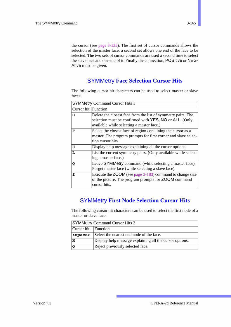
The SYMMetry Command 3-165
e to be select
slave
of a
ec-
t-
.
the cursor (see page 3-133). The first set of cursor commands allows thselection of the master face; a second set allows one end of the faceselected. The two sets of cursor commands are used a second time tothe slave face and one end of it. Finally the connection, POSItive or NEG-Ative must be given.
SYMMetry Face Selection Cursor Hits
The following cursor hit characters can be used to select master or faces:
SYMMetry First Node Selection Cursor Hits
The following cursor hit characters can be used to select the first nodemaster or slave face:
SYMMetry Command Cursor Hits 1Cursor hit Function D Delete the closest face from the list of symmetry pairs. The
selection must be confirmed with YES, NO or ALL. (Only available while selecting a master face.)
F Select the closest face of region containing the cursor as amaster. The program prompts for first corner and slave seltion cursor hits.
H Display help message explaining all the cursor options. L List the current symmetry pairs. (Only available while selec
ing a master face.) Q Leave SYMMetry command (while selecting a master face)
Forget master face (while selecting a slave face). Z Execute the ZOOM (see page 3-183) command to change size
of the picture. The program prompts for ZOOM command cursor hits.
SYMMetry Command Cursor Hits 2Cursor hit Function <space> Select the nearest end node of the face. H Display help message explaining all the cursor options. Q Reject previously selected face.
Version 7.1 OPERA-2d Reference Manual
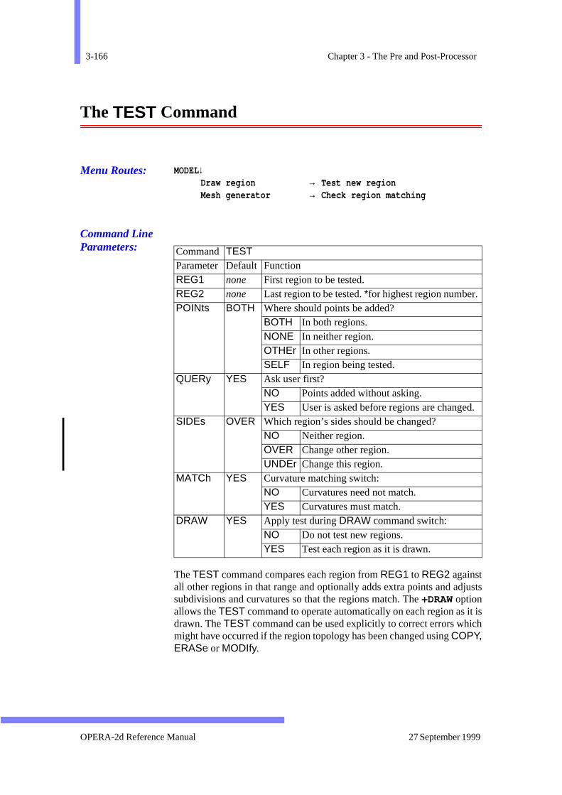
3-166 Chapter 3 - The Pre and Post-Processor
justs
it isich
.
The TEST Command
Menu Routes: MODEL↓Draw region → Test new regionMesh generator → Check region matching
Command Line Parameters:
The TEST command compares each region from REG1 to REG2 againstall other regions in that range and optionally adds extra points and adsubdivisions and curvatures so that the regions match. The +DRAW optionallows the TEST command to operate automatically on each region as drawn. The TEST command can be used explicitly to correct errors whmight have occurred if the region topology has been changed using COPY,ERASe or MODIfy.
Command TEST Parameter Default Function REG1 none First region to be tested. REG2 none Last region to be tested. *for highest region number. POINts BOTH Where should points be added?
BOTH In both regions. NONE In neither region. OTHEr In other regions. SELF In region being tested.
QUERy YES Ask user first? NO Points added without asking. YES User is asked before regions are changed
SIDEs OVER Which region’s sides should be changed? NO Neither region. OVER Change other region. UNDEr Change this region.
MATCh YES Curvature matching switch: NO Curvatures need not match. YES Curvatures must match.
DRAW YES Apply test during DRAW command switch: NO Do not test new regions. YES Test each region as it is drawn.
OPERA-2d Reference Manual 27 September 1999

The TEST Command 3-167
e endatch
verteing
hhe
isionsgion,
ust
cess ofcon-
Inserting Points
If two regions have sides which are collinear but do not share the sampoints, extra points can be added into the regions so that the sides mexactly. It is usually best to allow the program to add points into whicheregion it chooses (POIN=BOTH). However in some circumstances it mighbe better to restrict the program to adding points into either the region btested (POINt=SELF ) or the region it is being compared wit(POIN=OTHEr). If the program finds that an extra point is required, tuser can accept or reject it if QUERy=YES.
The point adding tests can be omitted by setting POINt=NONE.
Side Matching
If two regions have sides which share the same end points, the subdivand curvatures of one can be copied to the other. If while testing a rethere is a mis-match with a neighbouring regions and SIDEs=OVER, theneighbouring region is changed; if SIDEs=UNDEr, the region being testedis changed. If MATCh=YES the curvatures as well as the end points mmatch, and only the subdivisions will change.
The side matching tests can be omitted with SIDEs=NO.
Boundary Conditions
The TEST command also checks boundary conditions on adjoining faof regions. Any discrepancies are reported (e.g. two different valuepotential). These errors must be corrected by modifying the boundary ditions.
Version 7.1 OPERA-2d Reference Manual
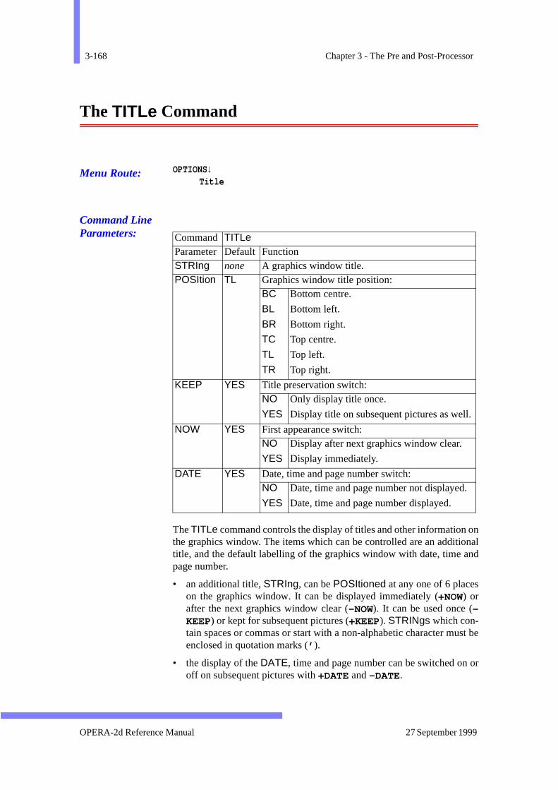
3-168 Chapter 3 - The Pre and Post-Processor
ononalnd
st be
or
The TITLe Command
Menu Route: OPTIONS↓Title
Command Line Parameters:
The TITLe command controls the display of titles and other informationthe graphics window. The items which can be controlled are an additititle, and the default labelling of the graphics window with date, time apage number.
• an additional title, STRIng, can be POSItioned at any one of 6 placeson the graphics window. It can be displayed immediately (+NOW) orafter the next graphics window clear (-NOW). It can be used once (-KEEP) or kept for subsequent pictures (+KEEP). STRINgs which con-tain spaces or commas or start with a non-alphabetic character muenclosed in quotation marks (’ ).
• the display of the DATE, time and page number can be switched onoff on subsequent pictures with +DATE and -DATE.
Command TITLe Parameter Default Function STRIng none A graphics window title. POSItion TL Graphics window title position:
BC Bottom centre.
BL Bottom left.
BR Bottom right.
TC Top centre.
TL Top left.
TR Top right.
KEEP YES Title preservation switch: NO Only display title once.
YES Display title on subsequent pictures as well.
NOW YES First appearance switch: NO Display after next graphics window clear.
YES Display immediately.
DATE YES Date, time and page number switch: NO Date, time and page number not displayed.
YES Date, time and page number displayed.
OPERA-2d Reference Manual 27 September 1999
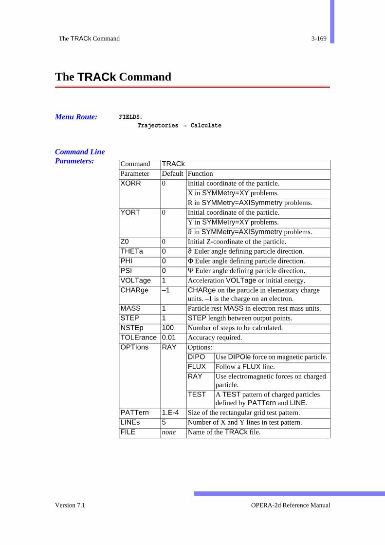
The TRACk Command 3-169
The TRACk Command
Menu Route: FIELDS↓Trajectories → Calculate
Command Line Parameters:
Command TRACk Parameter Default Function XORR 0 Initial coordinate of the particle.
X in SYMMetry=XY problems. R in SYMMetry=AXISymmetry problems.
YORT 0 Initial coordinate of the particle. Y in SYMMetry=XY problems. ϑ in SYMMetry=AXISymmetry problems.
Z0 0 Initial Z-coordinate of the particle. THETa 0 ϑ Euler angle defining particle direction. PHI 0 Φ Euler angle defining particle direction. PSI 0 Ψ Euler angle defining particle direction. VOLTage 1 Acceleration VOLTage or initial energy. CHARge –1 CHARge on the particle in elementary charge
units. –1 is the charge on an electron. MASS 1 Particle rest MASS in electron rest mass units. STEP 1 STEP length between output points. NSTEp 100 Number of steps to be calculated. TOLErance 0.01 Accuracy required. OPTIons RAY Options:
DIPO Use DIPOle force on magnetic particle. FLUX Follow a FLUX line. RAY Use electromagnetic forces on charged
particle. TEST A TEST pattern of charged particles
defined by PATTern and LINE. PATTern 1.E-4 Size of the rectangular grid test pattern. LINEs 5 Number of X and Y lines in test pattern. FILE none Name of the TRACk file.
Version 7.1 OPERA-2d Reference Manual
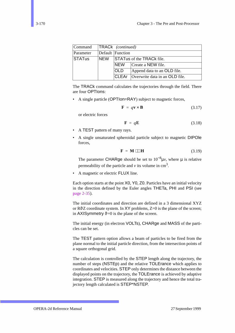
3-170 Chapter 3 - The Pre and Post-Processor
ere
YZn;
the of
he
tra-
The TRACk command calculates the trajectories through the field. Thare four OPTIons:
• A single particle (OPTIon=RAY) subject to magnetic forces,
(3.17)
or electric forces
(3.18)
• A TEST pattern of many rays.
• A single unsaturated spheroidal particle subject to magnetic DIPOleforces,
(3.19)
The parameter CHARge should be set to 10−8µv, where µ is relative
permeability of the particle and v its volume in cm3.
• A magnetic or electric FLUX line.
Each option starts at the point X0, Y0, Z0. Particles have an initial velocityin the direction defined by the Euler angles THETa, PHI and PSI (seepage 2-35).
The initial coordinates and direction are defined in a 3 dimensional Xor RϑZ coordinate system. In XY problems, Z=0 is the plane of the screein AXISymmetry ϑ=0 is the plane of the screen.
The initial energy (in electron VOLTs), CHARge and MASS of the parti-cles can be set.
The TEST pattern option allows a beam of particles to be fired from plane normal to the initial particle direction, from the intersection pointsa square orthogonal grid.
The calculation is controlled by the STEP length along the trajectory, thenumber of steps (NSTEp) and the relative TOLErance which applies tocoordinates and velocities. STEP only determines the distance between tdisplayed points on the trajectory, the TOLErance is achieved by adaptiveintegration. STEP is measured along the trajectory and hence the totaljectory length calculated is STEP*NSTEP.
STATus NEW STATus of the TRACk file. NEW Create a NEW file. OLD Append data to an OLD file. CLEAr Overwrite data in an OLD file.
Command TRACk (continued)
Parameter Default Function
F qv B×=
F qE=
F M ∇H⋅=
OPERA-2d Reference Manual 27 September 1999

The TRACk Command 3-171
atustusthirdck
ated.
for-
t be.
thethe
.
.
.
o
The trajectory coordinates are stored in a binary file. When the file stis set to NEW, a new file will be created to contain the data. Setting stato OLD causes the trajectories to be appended to an existing file. The option CLEAr causes an old file to be overwritten. The format of the trafile is described in the section on TRACk Files below.
The trajectories are drawn on the current display as they are calculSubsequently the contents of the TRACk files can be VIEWed in a numberof ways (see page 3-178).
TRACk Files
The TRACk command stores the trajectory coordinates in a binary unmatted file which can be read by the VIEW command (see page 3-178).Track files have file name extension track.
There is no indication of the number of tracks in the file; the data musread with end and error control to detect when all data has been read
The contents of the file is as follows:
Record 1: 20 INTEGERs. In track files created by the post-processor, only first value is important. It contains the number of points on track, NSTEP.
Record 2: 20 DOUBLE PRECISION values, RTRAK.
RTRAK(1) is the current associated with the track.
RTRAK(2) is the mass.
RTRAK(3) is the charge.
RTRAK(4) is the step-length
RTRAK(5-20) can be ignored.
Record 3: NSTEP DOUBLE PRECISION values, x coordinates of the track points
Record 4: NSTEP DOUBLE PRECISION values, y coordinates of the track points
Record 5: NSTEP DOUBLE PRECISION values, z coordinates of the track points
Record 6: NSTEP DOUBLE PRECISION values, x-component of the velocity.
Record 7: NSTEP DOUBLE PRECISION values, y-component of the velocity.
Record 8: NSTEP DOUBLE PRECISION values, z-component of the velocity.
On UNIX and OpenVMS systems, if NSTEP is greater than 500, records 3 t8 are blocked into sub-records which contain 500 DOUBLE PRECISION words.
Version 7.1 OPERA-2d Reference Manual
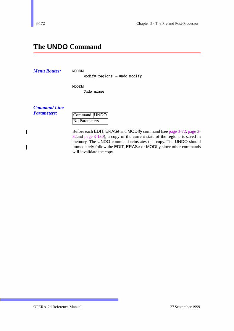
3-172 Chapter 3 - The Pre and Post-Processor
in
The UNDO Command
Menu Routes: MODEL↓Modify regions → Undo modify
MODEL↓Undo erase
Command Line Parameters:
Before each EDIT, ERASe and MODIfy command (see page 3-72, page 3-82and page 3-130), a copy of the current state of the regions is savedmemory. The UNDO command reinstates this copy. The UNDO shouldimmediately follow the EDIT, ERASe or MODIfy since other commandswill invalidate the copy.
Command UNDONo Parameters
OPERA-2d Reference Manual 27 September 1999
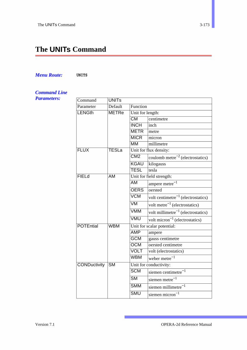
The UNITs Command 3-173
The UNITs Command
Menu Route: UNITS
Command Line Parameters:
Command UNITs Parameter Default Function LENGth METRe Unit for length:
CM centimetre INCH inch METR metre MICR micron MM millimetre
FLUX TESLa Unit for flux density: CM2 coulomb metre−2 (electrostatics)KGAU kilogauss TESL tesla
FIELd AM Unit for field strength: AM ampere metre−1
OERS oersted VCM volt centimetre−1 (electrostatics) VM volt metre−1 (electrostatics) VMM volt millimetre−1 (electrostatics) VMU volt micron−1 (electrostatics)
POTEntial WBM Unit for scalar potential: AMP ampere GCM gauss centimetre OCM oersted centimetre VOLT volt (electrostatics) WBM weber metre−1
CONDuctivity SM Unit for conductivity: SCM siemen centimetre−1
SM siemen metre−1
SMM siemen millimetre−1
SMU siemen micron−1
Version 7.1 OPERA-2d Reference Manual

3-174 Chapter 3 - The Pre and Post-Processor
ando oneused
l-hesen the
The UNITs command sets the units to be used to interpret user inputdisplay geometric and field data. Each of the parameters can be set tof a set of predefined character strings corresponding to commonly units.
The default set of units is S.I. Note that if the result of a post-processing caculation gives a numerical quantity whose units are the product of tbasic quantities, any changes made to the units will also be reflected icompound unit. For example, if the user has set the length unit to MM butleft the force in NEWTon, torque values computed by the INTL commandwill be in N-mm, not N-m.
DENSity AM2 Unit for current/charge density: ACM2 ampere centimetre−2
AIN2 ampere inch−2
AM2 ampere metre−2
AMM2 ampere millimetre−2
AMU2 ampere micron−2
CCM3 coulomb centimetre−3
MCM3 micro coulomb metre−3
POWEr WATT Unit for power: ERGS erg second HP horse power WATT watt
FORCe NEWTon Unit for force: DYNE dyne GRAM gramme force KGF kilogramme force LBF pound force NEWT newton
ENERgy JOULe Unit for energy: BTU British Thermal Unit CALO Calorie ERG erg JOULe joule
MASS KG Unit for mass: GRAM gramme KG kilogramme LB pound
Command UNITs (continued)
Parameter Default Function
OPERA-2d Reference Manual 27 September 1999

The UNITs Command 3-175
d are
with
The current units are stored in OPERA-2d data and results files, anreinstated when a file is READ (see page 3-147). The UNITs command isalso included in a COMOutput file (see page 3-31). The parameter valuescan be changed before reading the file back into the program $ COMInput (see page 2-28) in order to scale the data.
The VIEW command does not use the DENSity unit but has its own unit
for the display of current density: it uses amp LENGth-2(page 3-181).
Version 7.1 OPERA-2d Reference Manual

3-176 Chapter 3 - The Pre and Post-Processor
hes.
s.
s.
The VECTor Command
Menu Route: FIELDS↓Vectors
Command Line Parameters:
The VECTor command evaluates field quantities on 4 or 8-noded patc
Command VECTor Parameter Default Function Xn 0 X or R coordinate of nth point defining patch. Points
1 to 4 are corners; points 5 to 8 are mid-side pointYn 0 Y or Z coordinate of nth point defining patch. Points
1 to 4 are corners; points 5 to 8 are mid-side pointCORNers 4 Number of points defining patch: 4 or 8. N1 10 Number of points between corners 1 and 2, and
between corners 3 and 4. N2 10 Number of points between corners 1 and 4 and
between corners 2 and 3. VX BX Expression for x-component of vectors. VY BY Expression for y-component of vectors. TIME 0 For Steady-state ac solutions only: time at which
basic field quantities are evaluated. number Angle in degrees around ac cycle. AMPL Amplitude. PHAS Phase angle. TAVE Time average.
ERASe NO Picture erase switch: NO Old picture not erased. YES Old picture erased.
VECTor YES Vector display switch: NO No vector display. YES Vectors displayed.
PRINt NO Printed values switch: NO No printed values. YES Values printed to file opera2.lp.
LABEl YES Vector component labelling switch: NO No labels. YES Component expressions shown.
OPERA-2d Reference Manual 27 September 1999
The VECTor Command 3-177
alues
3);oint
tionape
-
e ofc-
re-
The results can be displayed as vectors at each field point and the vcan be printed in the file Opera2d_PP_n.lp.
The patch is specified by the points (X1,Y1, ..., X8,Y8). The mid-sidepoints are ignored if CORNers=4, and included if CORNers=8. Point 5is on side 1 (point 1 to point 2); point 6 is on side 2 (point 2 to pointpoint 7 is on side 3 (point 3 to point 4); point 8 is on side 4 (point 4 to p1).
It does not matter if the patch extends beyond the limits of the mesh.
The field quantities are evaluated at N1*N2 points. The coordinates ofpoints other than the corner and mid-side points are found by interpolausing 4 or 8-noded isoparametric two-dimensional finite element shfunctions.
Expressions for the vector components, VX and VY can use as variablesany of the system variables given in page 3-10. For Steady-state ac solutions, each system variable in an expression is evaluated at the TIME spec-ified. The size of the vectors in current length units gives the magnitudthe vector quantity (VX,VY). Vectors can be scaled by using a scaling fator in the expressions for VX and VY. The system variable MAXIMUM isset to the length of the longest vector.
The other parameters are switches: ±VECTor controls whether vectors aredisplayed, and if they are ±LABEl controls whether the expressions adisplayed on the graphics window; ±PRINt controls whether the component values are written to the file opera2.lp.
Version 7.1 OPERA-2d Reference Manual
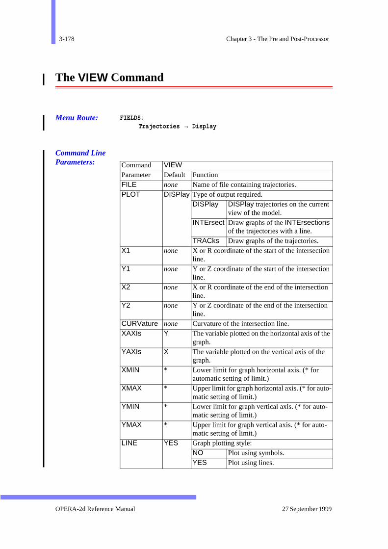
3-178 Chapter 3 - The Pre and Post-Processor
e
The VIEW Command
Menu Route: FIELDS↓Trajectories → Display
Command Line Parameters:
Command VIEW Parameter Default Function FILE none Name of file containing trajectories. PLOT DISPlay Type of output required.
DISPlay DISPlay trajectories on the current view of the model.
INTErsect Draw graphs of the INTErsections of the trajectories with a line.
TRACks Draw graphs of the trajectories.X1 none X or R coordinate of the start of the intersection
line.Y1 none Y or Z coordinate of the start of the intersection
line.X2 none X or R coordinate of the end of the intersection
line.Y2 none Y or Z coordinate of the end of the intersection
line.CURVature none Curvature of the intersection line.XAXIs Y The variable plotted on the horizontal axis of th
graph.YAXIs X The variable plotted on the vertical axis of the
graph.XMIN * Lower limit for graph horizontal axis. (* for
automatic setting of limit.)XMAX * Upper limit for graph horizontal axis. (* for auto-
matic setting of limit.)YMIN * Lower limit for graph vertical axis. (* for auto-
matic setting of limit.)YMAX * Upper limit for graph vertical axis. (* for auto-
matic setting of limit.)LINE YES Graph plotting style:
NO Plot using symbols.YES Plot using lines.
OPERA-2d Reference Manual 27 September 1999
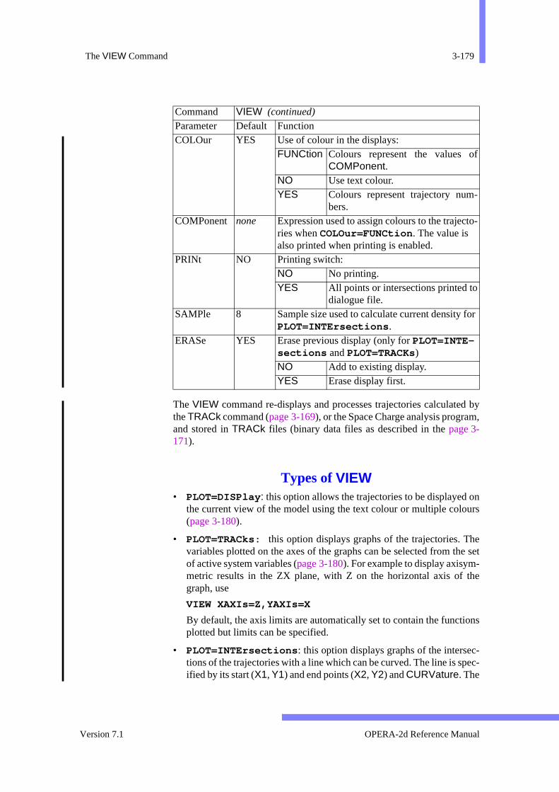
The VIEW Command 3-179
d bym,
onurs
hee set
-he
ons
c-pec-
f
-
to-
or
The VIEW command re-displays and processes trajectories calculatethe TRACk command (page 3-169), or the Space Charge analysis prograand stored in TRACk files (binary data files as described in the page 3-171).
Types of VIEW• PLOT=DISPlay : this option allows the trajectories to be displayed
the current view of the model using the text colour or multiple colo(page 3-180).
• PLOT=TRACks: this option displays graphs of the trajectories. Tvariables plotted on the axes of the graphs can be selected from thof active system variables (page 3-180). For example to display axisymmetric results in the ZX plane, with Z on the horizontal axis of tgraph, use
VIEW XAXIs=Z,YAXIs=X
By default, the axis limits are automatically set to contain the functiplotted but limits can be specified.
• PLOT=INTErsections : this option displays graphs of the intersetions of the trajectories with a line which can be curved. The line is sified by its start (X1, Y1) and end points (X2, Y2) and CURVature. The
COLOur YES Use of colour in the displays:FUNCtion Colours represent the values o
COMPonent.NO Use text colour.YES Colours represent trajectory num
bers.COMPonent none Expression used to assign colours to the trajec
ries when COLOur=FUNCtion . The value is also printed when printing is enabled.
PRINt NO Printing switch:NO No printing.YES All points or intersections printed to
dialogue file.SAMPle 8 Sample size used to calculate current density f
PLOT=INTErsections .ERASe YES Erase previous display (only for PLOT=INTE-
sections and PLOT=TRACKs)NO Add to existing display.YES Erase display first.
Command VIEW (continued) Parameter Default Function
Version 7.1 OPERA-2d Reference Manual

3-180 Chapter 3 - The Pre and Post-Processor
aria-entated thel bee
lues
exterthe
pres-e sys-
he
aila-
y)
intersections are plotted as graphs using the set of active system vbles (page 3-180). When the intersections are calculated, the currdensity is also computed for each intersection point. This is evalustatistically using varying sample sizes up to a maximum given bySAMPle parameter. The expected error is also calculated and wildisplayed using error bars if YAXIs=J is selected. The sample siz
should be less than of the number of intersections. If larger va
are used the results will be smooth but the errors will be larger.
VIEWing in COLOur
In each of the PLOTting options, the lines can be displayed using the tcolour (COLOur=NO), with colours representing the trajectory numb(COLOur=YES) or with colours representing some characteristic of position along the trajectory (COLOur=FUNCtion ).
Functional colours are selected using the value of the COMPonent exsion. COMPonent can be assigned to expressions in terms of the activtem variables listed below. For example,
COLOur=FUNCtion,COMPonent=TOF
will display the graphs coloured according to the time of flight from tstart points.
Active System Variables
The VIEW command has its own set of system variables which are avble in expressions for the graph plotting variables (XAXIs and YAXIs) andthe COMPonent used to determine the colours of the lines.
System Variables for PLOT=DISPlay and PLOT=TRACks
X X coordinates of points on the trajectoryY Y coordinates of points on the trajectoryZ Z coordinates of points on the trajectoryR Radial coordinate of points on trajectory (axisymmetry onlVELX X component of particle velocityVELY Y component of particle velocityVELZ Z component of particle velocityCURRENT The current in the track (beamlet).TOF Time of flight from the start of the trajectory.Q Electronic charge on the particle.M Mass of the particle in electron units.
110------
OPERA-2d Reference Manual 27 September 1999
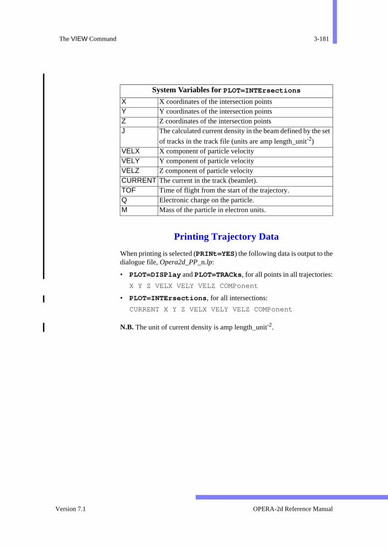
The VIEW Command 3-181
set
Printing Trajectory Data
When printing is selected (PRINt=YES ) the following data is output to thedialogue file, Opera2d_PP_n.lp:
• PLOT=DISPlay and PLOT=TRACks, for all points in all trajectories:
X Y Z VELX VELY VELZ COMPonent
• PLOT=INTErsections , for all intersections:
CURRENT X Y Z VELX VELY VELZ COMPonent
N.B. The unit of current density is amp length_unit-2.
System Variables for PLOT=INTErsections
X X coordinates of the intersection pointsY Y coordinates of the intersection pointsZ Z coordinates of the intersection pointsJ The calculated current density in the beam defined by the
of tracks in the track file (units are amp length_unit-2)VELX X component of particle velocityVELY Y component of particle velocityVELZ Z component of particle velocityCURRENT The current in the track (beamlet).TOF Time of flight from the start of the trajectory.Q Electronic charge on the particle.M Mass of the particle in electron units.
Version 7.1 OPERA-2d Reference Manual

3-182 Chapter 3 - The Pre and Post-Processor
tern-he the
ent/ files
ppliedor ines to
The WRITe Command
Menu Route: FILE ↓Write file → Write model
Command Line Parameters:
The WRITe command writes a OPERA-2d data file. The first paramedefines the name of the FILE. If no file name extension is given, and extesion op2 is assumed. If a solution exists it will be included in the file. If tmesh data exists it will also be written to a file. Mesh file names haveextension mesh.
OPERA-2d data files consist of the solution properties (SET command),the region data, the SYMMetry pairs, the BH curves and EXTRa dataincluding the current units set. If a solution exists, the potentials, currcharge densities and permeabilities/permittivities are appended. Theare formatted, but include little text to help them to be understood.
The thermal, stress and space charge beam analysis programs are suwith data and can return their solutions to the pre and post-processtables. Up to 10 tables can be written to a data file by giving their namparameters SOLn. For more information on setting up tables, see page 3-103.
Command WRITe Parameter Default Function FILE none Name of OPERA-2d data or results file. SOL1 none The name of an additional solution table. SOL2 none The name of an additional solution table. SOL3 none The name of an additional solution table. SOL4 none The name of an additional solution table. SOL5 none The name of an additional solution table. SOL6 none The name of an additional solution table. SOL7 none The name of an additional solution table. SOL8 none The name of an additional solution table. SOL9 none The name of an additional solution table. SO10 none The name of an additional solution table.
OPERA-2d Reference Manual 27 September 1999
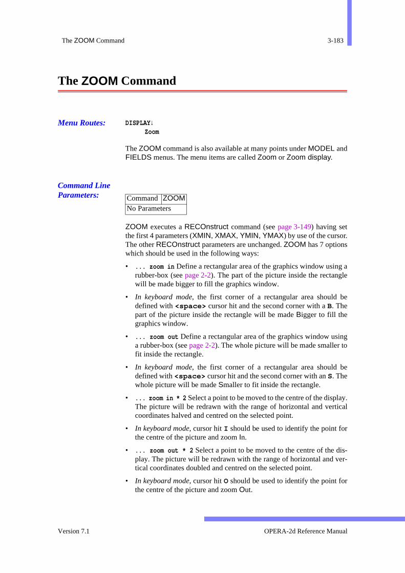
The ZOOM Command 3-183
g ale
be
ingo
be
lay.cal
r
is-er-
r
The ZOOM Command
Menu Routes: DISPLAY↓Zoom
The ZOOM command is also available at many points under MODEL andFIELDS menus. The menu items are called Zoom or Zoom display.
Command Line Parameters:
ZOOM executes a RECOnstruct command (see page 3-149) having setthe first 4 parameters (XMIN, XMAX, YMIN, YMAX) by use of the cursor.The other RECOnstruct parameters are unchanged. ZOOM has 7 optionswhich should be used in the following ways:
• ... zoom in Define a rectangular area of the graphics window usinrubber-box (see page 2-2). The part of the picture inside the rectangwill be made bigger to fill the graphics window.
• In keyboard mode, the first corner of a rectangular area should defined with <space> cursor hit and the second corner with a B. Thepart of the picture inside the rectangle will be made Bigger to fill thegraphics window.
• ... zoom out Define a rectangular area of the graphics window usa rubber-box (see page 2-2). The whole picture will be made smaller tfit inside the rectangle.
• In keyboard mode, the first corner of a rectangular area should defined with <space> cursor hit and the second corner with an S. Thewhole picture will be made Smaller to fit inside the rectangle.
• ... zoom in * 2 Select a point to be moved to the centre of the dispThe picture will be redrawn with the range of horizontal and verticoordinates halved and centred on the selected point.
• In keyboard mode, cursor hit I should be used to identify the point fothe centre of the picture and zoom In.
• ... zoom out * 2 Select a point to be moved to the centre of the dplay. The picture will be redrawn with the range of horizontal and vtical coordinates doubled and centred on the selected point.
• In keyboard mode, cursor hit O should be used to identify the point fothe centre of the picture and zoom Out.
Command ZOOMNo Parameters
Version 7.1 OPERA-2d Reference Manual
3-184 Chapter 3 - The Pre and Post-Processor
pic-or-
t
he
cs
kro-
cs
re
cs
of
csates
er
cs
• ... pan Select a point to be moved to the centre of the display. The ture will be redrawn with the same range of horizontal and vertical codinates but centred on the selected point.
• In keyboard mode, cursor hit P should be used to identify the poinwhich will become the new centre of the picture.
• Bounding box No further input is required. The program calculates tcoordinate limits to include all the regions selected for display.
• In keyboard mode, cursor hit B should be used anywhere in the graphiwindow to request bounding box.
• Previous size No further input is required. This option cycles bacthrough up to 20 sets of coordinate limits previously used in the pgram.
• In keyboard mode, cursor hit E should be used anywhere in the graphiwindow to request an earlier size.
• Same size No further input is required. This option redraws the pictuwith no change to the coordinate limits.
• In keyboard mode, cursor hit R should be used anywhere in the graphiwindow to request redraw.
• Text input Enter the values of the minimum and maximum valuesX and Y into the ParameterBox.
• In keyboard mode, cursor hit K should be used anywhere in the graphiwindow to request keyboard. The program prompts for the coordinof opposite corners to be given.
• Return No further input is required. This option returns to the highlevel menu without redrawing the picture.
• In keyboard mode, cursor hit Q should be used anywhere in the graphiwindow to request quit.
ZOOM is available as a sub-command in the DRAW, MODIfy and SYM-Metry commands (page 3-43, page 3-130 and page 3-164).
OPERA-2d Reference Manual 27 September 1999
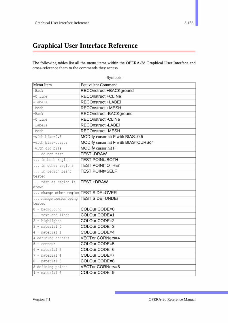
Graphical User Interface Reference 3-185
and
Graphical User Interface Reference
The following tables list all the menu items within the OPERA-2d Graphical User Interfacecross-reference them to the commands they access.
–Symbols–
Menu Item Equivalent Command +Back RECOnstruct +BACKground +C_line RECOnstruct +CLINe +Labels RECOnstruct +LABEl +Mesh RECOnstruct +MESH -Back RECOnstruct -BACKground -C_line RECOnstruct -CLINe -Labels RECOnstruct -LABEl -Mesh RECOnstruct -MESH -with bias=0.5 MODIfy cursor hit F with BIAS=0.5 -with bias=cursor MODIfy cursor hit F with BIAS=CURSor -with old bias MODIfy cursor hit F ... do not test TEST -DRAW ... in both regions TEST POINt=BOTH ... in other regions TEST POINt=OTHEr ... in region being tested
TEST POINt=SELF
... test as region is drawn
TEST +DRAW
... change other region TEST SIDE=OVER
... change region being tested
TEST SIDE=UNDEr
0 - background COLOur CODE=0 1 - text and lines COLOur CODE=1 2 - highlights COLOur CODE=2 3 - material 0 COLOur CODE=3 4 - material 1 COLOur CODE=4 4 defining corners VECTor CORNers=4 5 - contour COLOur CODE=5 6 - material 3 COLOur CODE=6 7 - material 4 COLOur CODE=7 8 - material 5 COLOur CODE=8 8 defining points VECTor CORNers=8 9 - material 6 COLOur CODE=9
Version 7.1 OPERA-2d Reference Manual
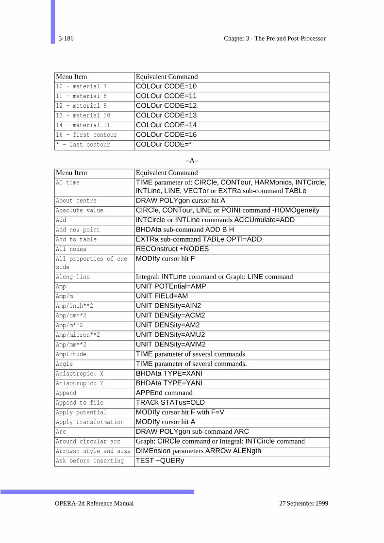
3-186 Chapter 3 - The Pre and Post-Processor
–A–
10 - material 7 COLOur CODE=10 11 - material 8 COLOur CODE=11 12 - material 9 COLOur CODE=12 13 - material 10 COLOur CODE=13 14 - material 11 COLOur CODE=14 16 - first contour COLOur CODE=16 * - last contour COLOur CODE=*
Menu Item Equivalent Command AC time TIME parameter of: CIRCle, CONTour, HARMonics, INTCircle,
INTLine, LINE, VECTor or EXTRa sub-command TABLe About centre DRAW POLYgon cursor hit A Absolute value CIRCle, CONTour, LINE or POINt command -HOMOgeneity Add INTCircle or INTLine commands ACCUmulate=ADD Add new point BHDAta sub-command ADD B H Add to table EXTRa sub-command TABLe OPTI=ADD All nodes RECOnstruct +NODES All properties of one side
MODIfy cursor hit F
Along line Integral: INTLine command or Graph: LINE command Amp UNIT POTEntial=AMP Amp/m UNIT FIELd=AM Amp/Inch**2 UNIT DENSity=AIN2 Amp/cm**2 UNIT DENSity=ACM2 Amp/m**2 UNIT DENSity=AM2 Amp/micron**2 UNIT DENSity=AMU2 Amp/mm**2 UNIT DENSity=AMM2 Amplitude TIME parameter of several commands. Angle TIME parameter of several commands. Anisotropic: X BHDAta TYPE=XANIAnisotropic: Y BHDAta TYPE=YANIAppend APPEnd command Append to file TRACk STATus=OLD Apply potential MODIfy cursor hit F with F=V Apply transformation MODIfy cursor hit A Arc DRAW POLYgon sub-command ARC Around circular arc Graph: CIRCle command or Integral: INTCircle command Arrows: style and size DIMEnsion parameters ARROw ALENgth Ask before inserting TEST +QUERy
Menu Item Equivalent Command
OPERA-2d Reference Manual 27 September 1999
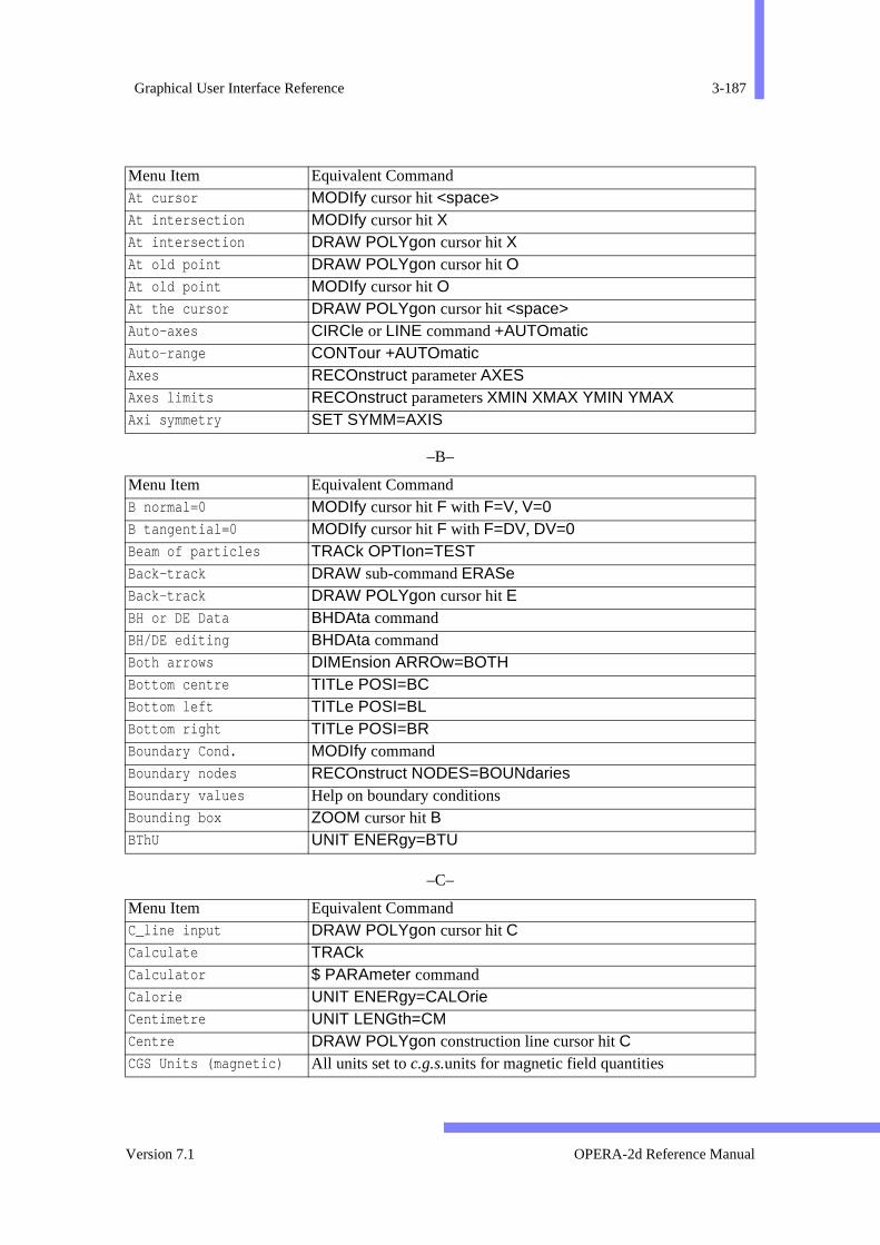
Graphical User Interface Reference 3-187
–B–
–C–
At cursor MODIfy cursor hit <space> At intersection MODIfy cursor hit X At intersection DRAW POLYgon cursor hit X At old point DRAW POLYgon cursor hit O At old point MODIfy cursor hit O At the cursor DRAW POLYgon cursor hit <space>Auto-axes CIRCle or LINE command +AUTOmatic Auto-range CONTour +AUTOmatic Axes RECOnstruct parameter AXES Axes limits RECOnstruct parameters XMIN XMAX YMIN YMAX Axi symmetry SET SYMM=AXIS
Menu Item Equivalent Command B normal=0 MODIfy cursor hit F with F=V, V=0 B tangential=0 MODIfy cursor hit F with F=DV, DV=0 Beam of particles TRACk OPTIon=TEST Back-track DRAW sub-command ERASe Back-track DRAW POLYgon cursor hit E BH or DE Data BHDAta command BH/DE editing BHDAta command Both arrows DIMEnsion ARROw=BOTH Bottom centre TITLe POSI=BC Bottom left TITLe POSI=BL Bottom right TITLe POSI=BR Boundary Cond. MODIfy command Boundary nodes RECOnstruct NODES=BOUNdaries Boundary values Help on boundary conditions Bounding box ZOOM cursor hit B BThU UNIT ENERgy=BTU
Menu Item Equivalent Command C_line input DRAW POLYgon cursor hit C Calculate TRACk Calculator $ PARAmeter command Calorie UNIT ENERgy=CALOrie Centimetre UNIT LENGth=CM Centre DRAW POLYgon construction line cursor hit C CGS Units (magnetic) All units set to c.g.s.units for magnetic field quantities
Menu Item Equivalent Command
Version 7.1 OPERA-2d Reference Manual
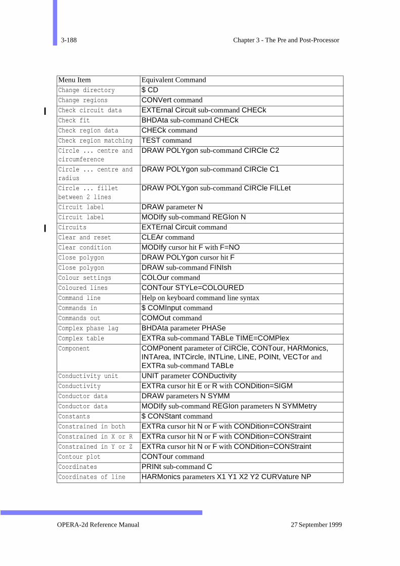
3-188 Chapter 3 - The Pre and Post-Processor
Change directory $ CD Change regions CONVert command Check circuit data EXTErnal Circuit sub-command CHECkCheck fit BHDAta sub-command CHECk Check region data CHECk command Check region matching TEST command Circle ... centre and circumference
DRAW POLYgon sub-command CIRCle C2
Circle ... centre and radius
DRAW POLYgon sub-command CIRCle C1
Circle ... fillet between 2 lines
DRAW POLYgon sub-command CIRCle FILLet
Circuit label DRAW parameter N Circuit label MODIfy sub-command REGIon N Circuits EXTErnal Circuit commandClear and reset CLEAr command Clear condition MODIfy cursor hit F with F=NO Close polygon DRAW POLYgon cursor hit F Close polygon DRAW sub-command FINIsh Colour settings COLOur command Coloured lines CONTour STYLe=COLOURED Command line Help on keyboard command line syntax Commands in $ COMInput command Commands out COMOut command Complex phase lag BHDAta parameter PHASeComplex table EXTRa sub-command TABLe TIME=COMPlex Component COMPonent parameter of CIRCle, CONTour, HARMonics,
INTArea, INTCircle, INTLine, LINE, POINt, VECTor and EXTRa sub-command TABLe
Conductivity unit UNIT parameter CONDuctivity Conductivity EXTRa cursor hit E or R with CONDition=SIGM Conductor data DRAW parameters N SYMM Conductor data MODIfy sub-command REGIon parameters N SYMMetry Constants $ CONStant command Constrained in both EXTRa cursor hit N or F with CONDition=CONStraint Constrained in X or R EXTRa cursor hit N or F with CONDition=CONStraint Constrained in Y or Z EXTRa cursor hit N or F with CONDition=CONStraint Contour plot CONTour command Coordinates PRINt sub-command C Coordinates of line HARMonics parameters X1 Y1 X2 Y2 CURVature NP
Menu Item Equivalent Command
OPERA-2d Reference Manual 27 September 1999
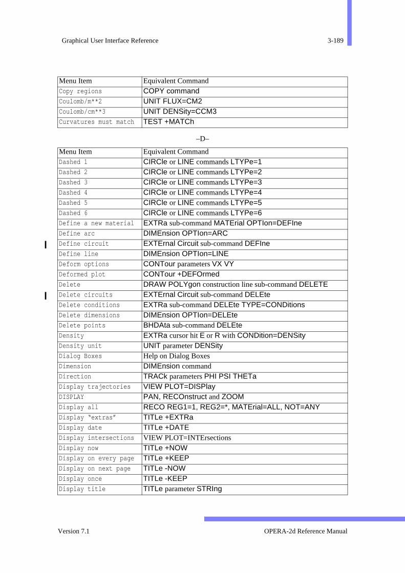
Graphical User Interface Reference 3-189
–D–
Copy regions COPY command Coulomb/m**2 UNIT FLUX=CM2 Coulomb/cm**3 UNIT DENSity=CCM3 Curvatures must match TEST +MATCh
Menu Item Equivalent Command Dashed 1 CIRCle or LINE commands LTYPe=1 Dashed 2 CIRCle or LINE commands LTYPe=2 Dashed 3 CIRCle or LINE commands LTYPe=3 Dashed 4 CIRCle or LINE commands LTYPe=4 Dashed 5 CIRCle or LINE commands LTYPe=5 Dashed 6 CIRCle or LINE commands LTYPe=6 Define a new material EXTRa sub-command MATErial OPTIon=DEFIne Define arc DIMEnsion OPTIon=ARC Define circuit EXTErnal Circuit sub-command DEFIneDefine line DIMEnsion OPTIon=LINE Deform options CONTour parameters VX VY Deformed plot CONTour +DEFOrmed Delete DRAW POLYgon construction line sub-command DELETE Delete circuits EXTErnal Circuit sub-command DELEte Delete conditions EXTRa sub-command DELEte TYPE=CONDitions Delete dimensions DIMEnsion OPTIon=DELEte Delete points BHDAta sub-command DELEte Density EXTRa cursor hit E or R with CONDition=DENSity Density unit UNIT parameter DENSity Dialog Boxes Help on Dialog Boxes Dimension DIMEnsion command Direction TRACk parameters PHI PSI THETa Display trajectories VIEW PLOT=DISPlay DISPLAY PAN, RECOnstruct and ZOOM Display all RECO REG1=1, REG2=*, MATErial=ALL, NOT=ANY Display “extras” TITLe +EXTRa Display date TITLe +DATE Display intersections VIEW PLOT=INTErsectionsDisplay now TITLe +NOW Display on every page TITLe +KEEP Display on next page TITLe -NOW Display once TITLe -KEEP Display title TITLe parameter STRIng
Menu Item Equivalent Command
Version 7.1 OPERA-2d Reference Manual
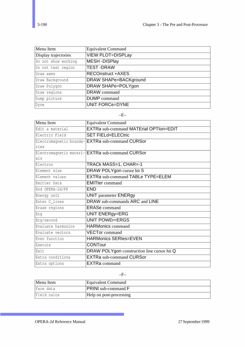
3-190 Chapter 3 - The Pre and Post-Processor
–E–
–F–
Display trajectories VIEW PLOT=DISPLayDo not show working MESH -DISPlay Do not test region TEST -DRAW Draw axes RECOnstruct +AXES Draw Background DRAW SHAPe=BACKground Draw Polygon DRAW SHAPe=POLYgon Draw regions DRAW command Dump picture DUMP command Dyne UNIT FORCe=DYNE
Menu Item Equivalent Command Edit a material EXTRa sub-command MATErial OPTIon=EDIT Electric Field SET FIELd=ELECtric Electromagnetic bounda-ries
EXTRa sub-command CURSor
Electromagnetic materi-als
EXTRa sub-command CURSor
Electron TRACk MASS=1, CHAR=-1 Element size DRAW POLYgon cursor hit S Element values EXTRa sub-command TABLe TYPE=ELEM Emitter Data EMITter command End OPERA-2d/PP END Energy unit UNIT parameter ENERgy Enter C_lines DRAW sub-commands ARC and LINE Erase regions ERASe command Erg UNIT ENERgy=ERG Erg/second UNIT POWEr=ERGS Evaluate harmonics HARMonics command Evaluate vectors VECTor command Even function HARMonics SERIes=EVEN Execute CONTour Exit DRAW POLYgon construction line cursor hit Q Extra conditions EXTRa sub-command CURSor Extra options EXTRa command
Menu Item Equivalent Command Face data PRINt sub-command F Field calcs Help on post-processing
Menu Item Equivalent Command
OPERA-2d Reference Manual 27 September 1999

Graphical User Interface Reference 3-191
om-
–G–
Field calculations Help on post-processing Field intensity UNIT parameter FIELd Field options SET command parameters INTEgral, FLDType, REFXaxis,
REFYaxis, ROTAtions, ROTSign, HXX and HYY.FIELDS Post-processing commands FILE Reading and writing data and command files; operating system c
mands; ending the program FileBoxes Help on File Boxes Fill elements RECOnstruct FILL=ELEMents Fill materials RECOnstruct FILL=MATErials Fill regions RECOnstruct FILL=REGIons Filled zones CONTour STYLe=ZONE Fixed temperature EXTRa cursor hit N or F with CONDition=TEMPerature Flux density unit UNIT parameter FLUX Flux line TRACk OPTIon=FLUX For all regions MODIfy cursor hit N Force unit UNIT parameter FORCe Fourier series HARMonics TYPE=FOURier Frequency SET parameter FREQuency Full period HARMonics PERIod=1 Function Keys Help on the use of function keys with the menus
Menu Item Equivalent Command Gauss UNIT FLUX=GAUSs Gauss cm UNIT POTEntial=GCM Generate mesh MESH command Getting help Help on command line help facilities Gram UNIT MASS=GRAM Gram force UNIT FORCe=GRAM Graph trajectories X VIEW PLOT=TRACks Graphics output DEVIce command Graphs CIRCle and LINEcommands Grid size (polar) DRAW POLYgon cursor hit PGrid size (xy) DRAW POLYgon cursor hit GGroup regions GROUp command
Menu Item Equivalent Command
Version 7.1 OPERA-2d Reference Manual
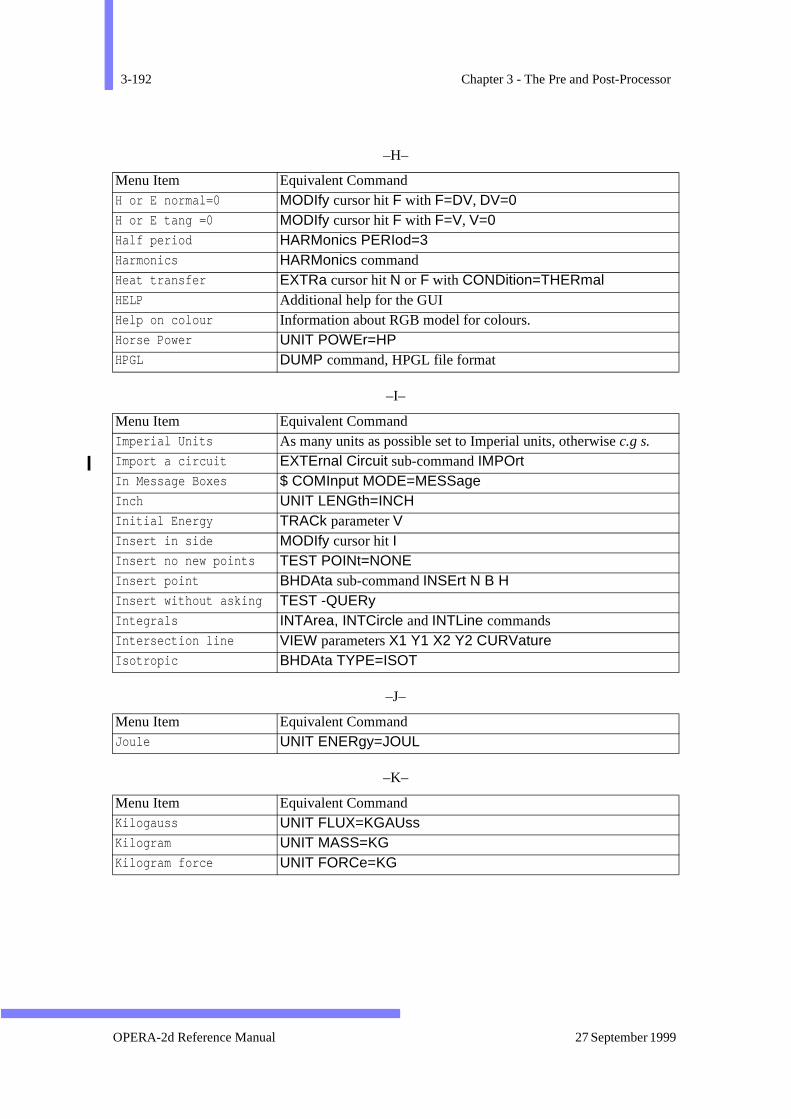
3-192 Chapter 3 - The Pre and Post-Processor
–H–
–I–
–J–
–K–
Menu Item Equivalent Command H or E normal=0 MODIfy cursor hit F with F=DV, DV=0 H or E tang =0 MODIfy cursor hit F with F=V, V=0 Half period HARMonics PERIod=3 Harmonics HARMonics command Heat transfer EXTRa cursor hit N or F with CONDition=THERmal HELP Additional help for the GUI Help on colour Information about RGB model for colours. Horse Power UNIT POWEr=HP HPGL DUMP command, HPGL file format
Menu Item Equivalent Command Imperial Units As many units as possible set to Imperial units, otherwise c.g s. Import a circuit EXTErnal Circuit sub-command IMPOrtIn Message Boxes $ COMInput MODE=MESSage Inch UNIT LENGth=INCH Initial Energy TRACk parameter V Insert in side MODIfy cursor hit I Insert no new points TEST POINt=NONE Insert point BHDAta sub-command INSErt N B H Insert without asking TEST -QUERy Integrals INTArea, INTCircle and INTLine commands Intersection line VIEW parameters X1 Y1 X2 Y2 CURVature Isotropic BHDAta TYPE=ISOT
Menu Item Equivalent Command Joule UNIT ENERgy=JOUL
Menu Item Equivalent Command Kilogauss UNIT FLUX=KGAUss Kilogram UNIT MASS=KG Kilogram force UNIT FORCe=KG
OPERA-2d Reference Manual 27 September 1999
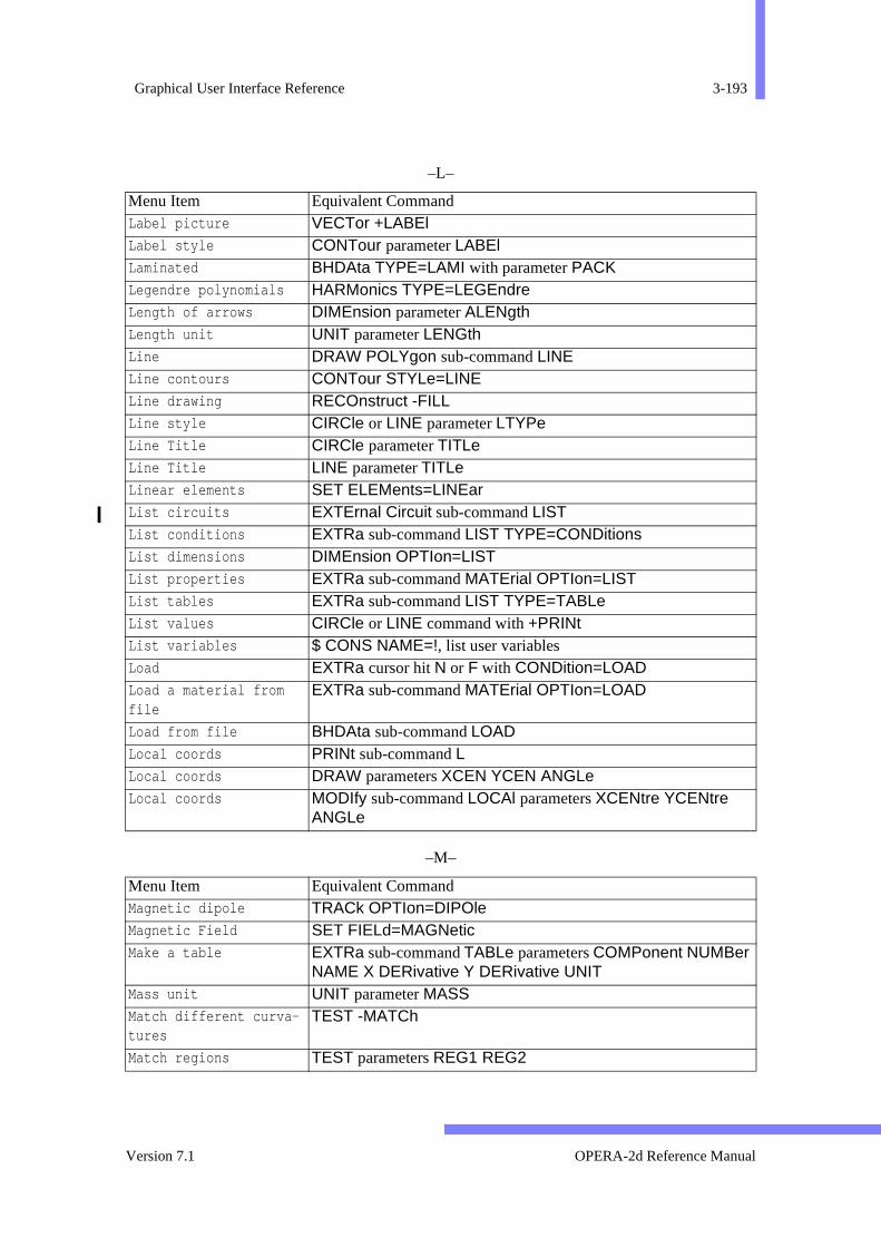
Graphical User Interface Reference 3-193
–L–
–M–
Menu Item Equivalent Command Label picture VECTor +LABEl Label style CONTour parameter LABEl Laminated BHDAta TYPE=LAMI with parameter PACKLegendre polynomials HARMonics TYPE=LEGEndre Length of arrows DIMEnsion parameter ALENgth Length unit UNIT parameter LENGth Line DRAW POLYgon sub-command LINE Line contours CONTour STYLe=LINE Line drawing RECOnstruct -FILL Line style CIRCle or LINE parameter LTYPe Line Title CIRCle parameter TITLe Line Title LINE parameter TITLe Linear elements SET ELEMents=LINEar List circuits EXTErnal Circuit sub-command LIST List conditions EXTRa sub-command LIST TYPE=CONDitions List dimensions DIMEnsion OPTIon=LIST List properties EXTRa sub-command MATErial OPTIon=LIST List tables EXTRa sub-command LIST TYPE=TABLe List values CIRCle or LINE command with +PRINt List variables $ CONS NAME=!, list user variables Load EXTRa cursor hit N or F with CONDition=LOAD Load a material from file
EXTRa sub-command MATErial OPTIon=LOAD
Load from file BHDAta sub-command LOAD Local coords PRINt sub-command L Local coords DRAW parameters XCEN YCEN ANGLe Local coords MODIfy sub-command LOCAl parameters XCENtre YCENtre
ANGLe
Menu Item Equivalent Command Magnetic dipole TRACk OPTIon=DIPOle Magnetic Field SET FIELd=MAGNetic Make a table EXTRa sub-command TABLe parameters COMPonent NUMBer
NAME X DERivative Y DERivative UNIT Mass unit UNIT parameter MASS Match different curva-tures
TEST -MATCh
Match regions TEST parameters REG1 REG2
Version 7.1 OPERA-2d Reference Manual
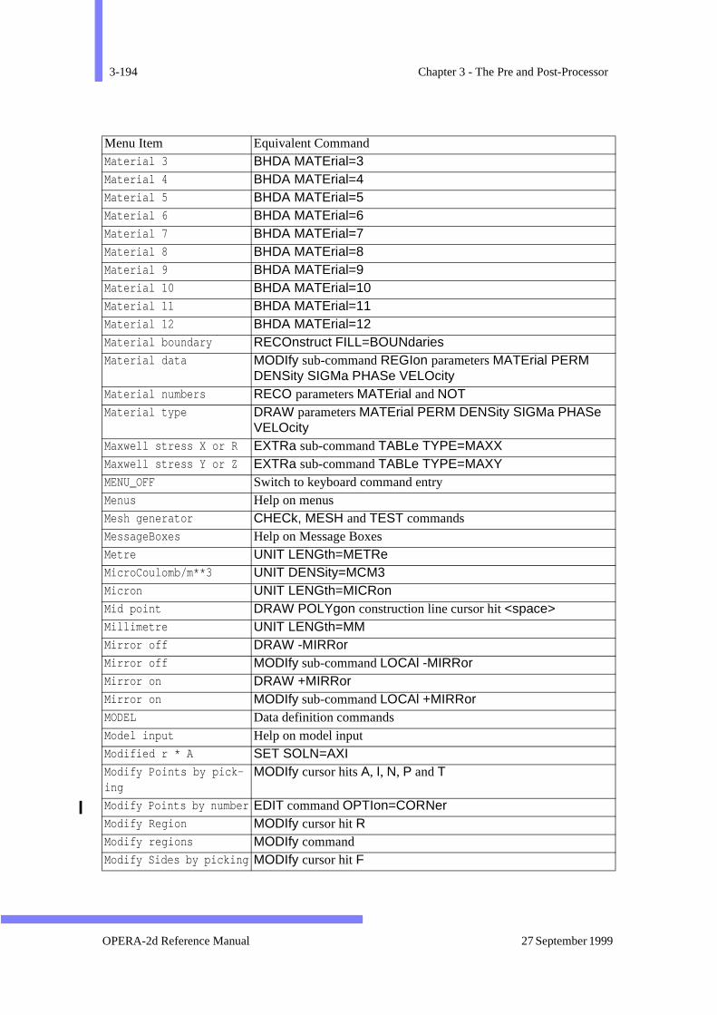
3-194 Chapter 3 - The Pre and Post-Processor
Material 3 BHDA MATErial=3 Material 4 BHDA MATErial=4 Material 5 BHDA MATErial=5 Material 6 BHDA MATErial=6 Material 7 BHDA MATErial=7 Material 8 BHDA MATErial=8 Material 9 BHDA MATErial=9 Material 10 BHDA MATErial=10 Material 11 BHDA MATErial=11 Material 12 BHDA MATErial=12 Material boundary RECOnstruct FILL=BOUNdaries Material data MODIfy sub-command REGIon parameters MATErial PERM
DENSity SIGMa PHASe VELOcity Material numbers RECO parameters MATErial and NOTMaterial type DRAW parameters MATErial PERM DENSity SIGMa PHASe
VELOcity Maxwell stress X or R EXTRa sub-command TABLe TYPE=MAXX Maxwell stress Y or Z EXTRa sub-command TABLe TYPE=MAXY MENU_OFF Switch to keyboard command entry Menus Help on menus Mesh generator CHECk, MESH and TEST commands MessageBoxes Help on Message Boxes Metre UNIT LENGth=METRe MicroCoulomb/m**3 UNIT DENSity=MCM3 Micron UNIT LENGth=MICRon Mid point DRAW POLYgon construction line cursor hit <space>Millimetre UNIT LENGth=MM Mirror off DRAW -MIRRor Mirror off MODIfy sub-command LOCAl -MIRRor Mirror on DRAW +MIRRor Mirror on MODIfy sub-command LOCAl +MIRRor MODEL Data definition commands Model input Help on model input Modified r * A SET SOLN=AXI Modify Points by pick-ing
MODIfy cursor hits A, I, N, P and T
Modify Points by number EDIT command OPTIon=CORNerModify Region MODIfy cursor hit R Modify regions MODIfy command Modify Sides by picking MODIfy cursor hit F
Menu Item Equivalent Command
OPERA-2d Reference Manual 27 September 1999

Graphical User Interface Reference 3-195
–N–
–O–
Modify Sides by number EDIT command OPTIon=SIDEMouse input DRAW sub-command CURSor Mouse pick POINt METH=CURSor mu or epsilon EXTRa cursor hit E or R with CONDition=PERM Multiple regions MODIfy command with parameters
Menu Item Equivalent Command Nearest C_line DRAW POLYgon cursor hit N Nearest C_line MODIfy cursor hit N New graph CIRCle or LINE +ERASe New region..Background DRAW command SHAPe=BACKgroundNew region ... Polygon DRAW command SHAPe=POLYgonNew region .. Rotating m/c Air Gap
DRAW command SHAPe=GAP
New table EXTRa sub-command TABLe OPTI=NEW Newton UNIT FORCe=NEWT No arrows DIMEnsion ARROW=NONE No axes RECOnstruct -AXES No labels VECTor -LABEl No Labels CONTour -LABEl No output $ COMInput MODE=OFF No Refresh CONTour -ERASe No Refresh VECTor -ERASe No values VECTor -PRIN No value list CIRCle or LINE command with -PRINt No vectors VECTor -VECTor No vertices/nodes RECOnstruct -NODES Nodal average values EXTRa sub-command TABLe TYPE=AVER Nodal values EXTRa sub-command TABLe TYPE=NODA Nodes RECOnstruct parameter NODEs None CONTour STYLe=NONE Number of lines CONTour parameter LINEs Number of points VECTor parameters N1 N2
Menu Item Equivalent Command Odd Function HARMonics SERIes=ODD Oersted UNIT FIELd=OERSted Oersted cm UNIT POTEntial=OCM
Menu Item Equivalent Command
Version 7.1 OPERA-2d Reference Manual
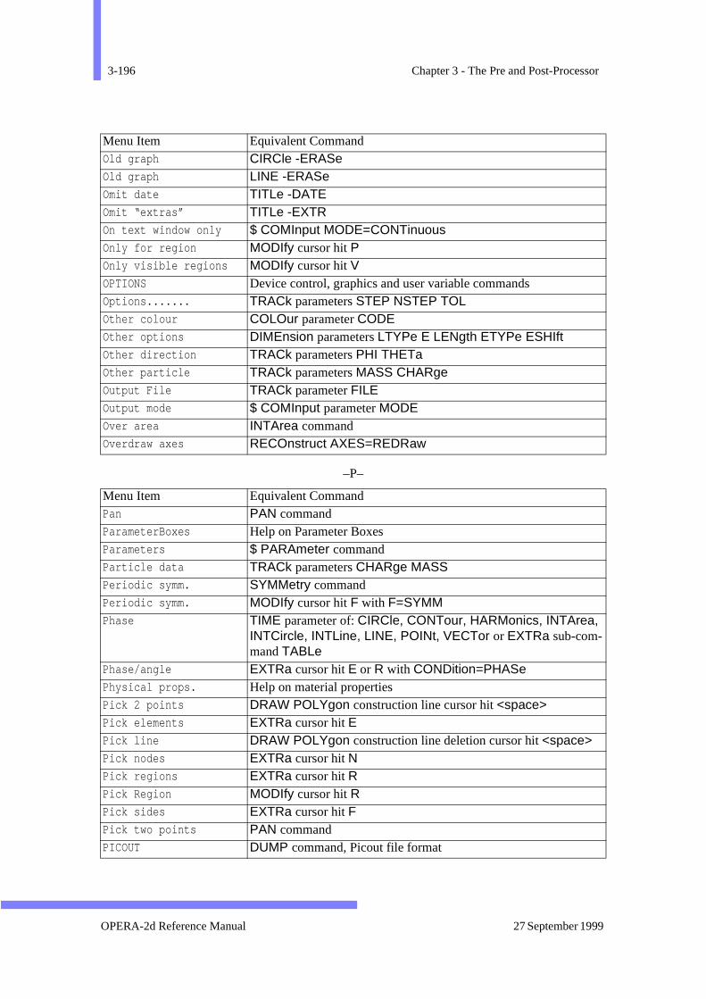
3-196 Chapter 3 - The Pre and Post-Processor
–P–
Old graph CIRCle -ERASe Old graph LINE -ERASe Omit date TITLe -DATE Omit “extras” TITLe -EXTR On text window only $ COMInput MODE=CONTinuous Only for region MODIfy cursor hit P Only visible regions MODIfy cursor hit V OPTIONS Device control, graphics and user variable commands Options....... TRACk parameters STEP NSTEP TOL Other colour COLOur parameter CODE Other options DIMEnsion parameters LTYPe E LENgth ETYPe ESHIft Other direction TRACk parameters PHI THETa Other particle TRACk parameters MASS CHARge Output File TRACk parameter FILEOutput mode $ COMInput parameter MODE Over area INTArea command Overdraw axes RECOnstruct AXES=REDRaw
Menu Item Equivalent Command Pan PAN command ParameterBoxes Help on Parameter Boxes Parameters $ PARAmeter command Particle data TRACk parameters CHARge MASS Periodic symm. SYMMetry command Periodic symm. MODIfy cursor hit F with F=SYMM Phase TIME parameter of: CIRCle, CONTour, HARMonics, INTArea,
INTCircle, INTLine, LINE, POINt, VECTor or EXTRa sub-com-mand TABLe
Phase/angle EXTRa cursor hit E or R with CONDition=PHASe Physical props. Help on material properties Pick 2 points DRAW POLYgon construction line cursor hit <space>Pick elements EXTRa cursor hit E Pick line DRAW POLYgon construction line deletion cursor hit <space>Pick nodes EXTRa cursor hit N Pick regions EXTRa cursor hit R Pick Region MODIfy cursor hit R Pick sides EXTRa cursor hit F Pick two points PAN command PICOUT DUMP command, Picout file format
Menu Item Equivalent Command
OPERA-2d Reference Manual 27 September 1999
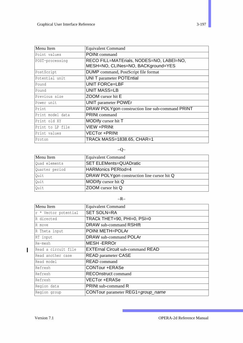
Graphical User Interface Reference 3-197
–Q–
–R–
Point values POINt command POST-processing RECO FILL=MATErials, NODES=NO, LABEl=NO,
MESH=NO, CLINes=NO, BACKground=YESPostScript DUMP command, PostScript file format Potential unit UNI T parameter POTEntial Pound UNIT FORCe=LBF Pound UNIT MASS=LB Previous size ZOOM cursor hit EPower unit UNIT parameter POWEr Print DRAW POLYgon construction line sub-command PRINT Print model data PRINt command Print old XY MODIfy cursor hit T Print to LP file VIEW +PRINt Print values VECTor +PRINt Proton TRACk MASS=1838.65, CHAR=1
Menu Item Equivalent Command Quad elements SET ELEMents=QUADratic Quarter period HARMonics PERIod=4 Quit DRAW POLYgon construction line cursor hit Q Quit MODIfy cursor hit Q Quit ZOOM cursor hit Q
Menu Item Equivalent Command r * Vector potential SET SOLN=RA R directed TRACk THET=90, PHI=0, PSI=0 R move DRAW sub-command RSHIft R Theta input POINt METH=POLAr RT input DRAW sub-command POLAr Re-mesh MESH -ERROr Read a circuit file EXTErnal Circuit sub-command READRead another case READ parameter CASE Read model READ command Refresh CONTour +ERASe Refresh RECOnstruct command Refresh VECTor +ERASe Region data PRINt sub-command R Region group CONTour parameter REG1=group_name
Menu Item Equivalent Command
Version 7.1 OPERA-2d Reference Manual
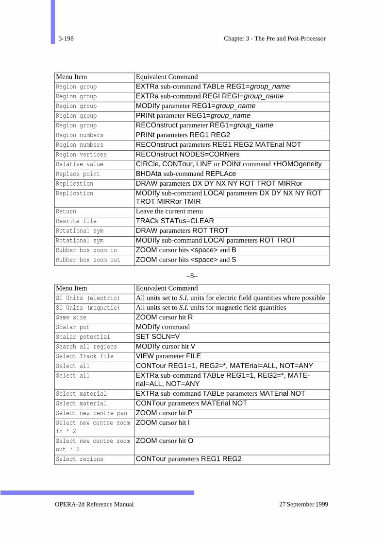
3-198 Chapter 3 - The Pre and Post-Processor
–S–
Region group EXTRa sub-command TABLe REG1=group_nameRegion group EXTRa sub-command REGI REGI=group_nameRegion group MODIfy parameter REG1=group_nameRegion group PRINt parameter REG1=group_nameRegion group RECOnstruct parameter REG1=group_nameRegion numbers PRINt parameters REG1 REG2 Region numbers RECOnstruct parameters REG1 REG2 MATErial NOT Region vertices RECOnstruct NODES=CORNers Relative value CIRCle, CONTour, LINE or POINt command +HOMOgeneity Replace point BHDAta sub-command REPLAce Replication DRAW parameters DX DY NX NY ROT TROT MIRRor Replication MODIfy sub-command LOCAl parameters DX DY NX NY ROT
TROT MIRRor TMIR Return Leave the current menu Rewrite file TRACk STATus=CLEAR Rotational sym DRAW parameters ROT TROT Rotational sym MODIfy sub-command LOCAl parameters ROT TROT Rubber box zoom in ZOOM cursor hits <space> and B Rubber box zoom out ZOOM cursor hits <space> and S
Menu Item Equivalent Command SI Units (electric) All units set to S.I. units for electric field quantities where possibleSI Units (magnetic) All units set to S.I. units for magnetic field quantities Same size ZOOM cursor hit R Scalar pot MODIfy command Scalar potential SET SOLN=V Search all regions MODIfy cursor hit V Select Track file VIEW parameter FILESelect all CONTour REG1=1, REG2=*, MATErial=ALL, NOT=ANY Select all EXTRa sub-command TABLe REG1=1, REG2=*, MATE-
rial=ALL, NOT=ANY Select material EXTRa sub-command TABLe parameters MATErial NOT Select material CONTour parameters MATErial NOT Select new centre pan ZOOM cursor hit P Select new centre zoom in * 2
ZOOM cursor hit I
Select new centre zoom out * 2
ZOOM cursor hit O
Select regions CONTour parameters REG1 REG2
Menu Item Equivalent Command
OPERA-2d Reference Manual 27 September 1999
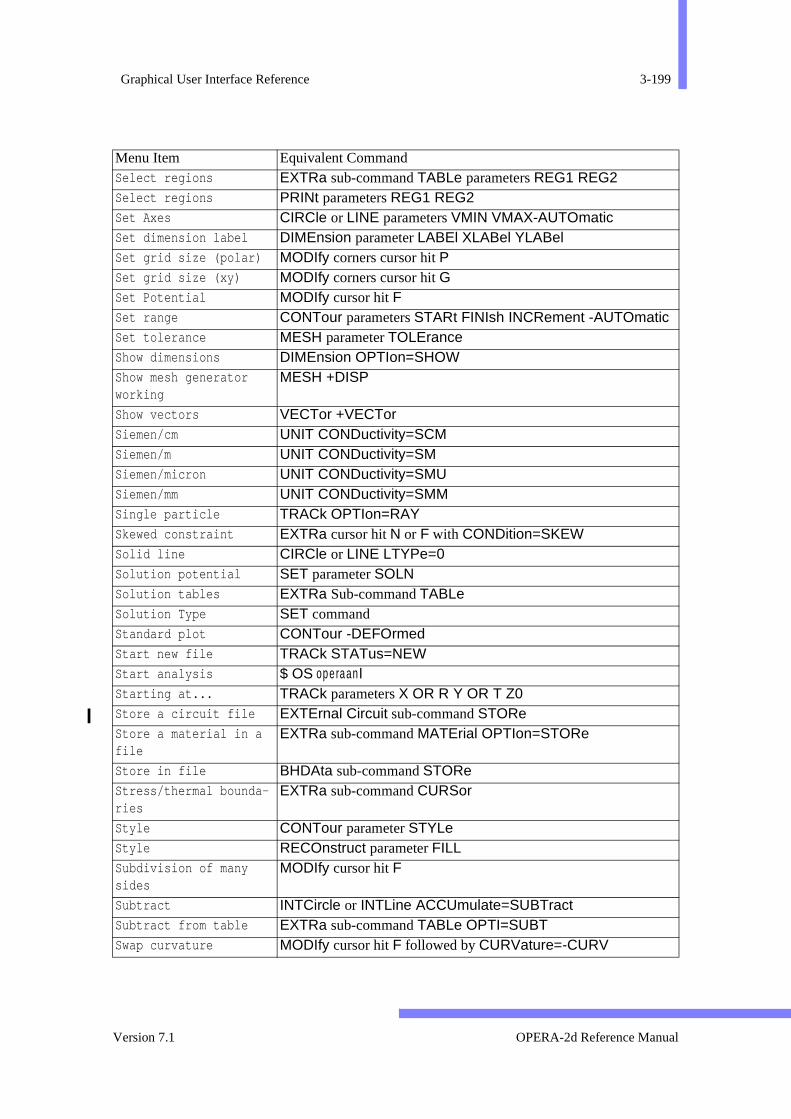
Graphical User Interface Reference 3-199
Select regions EXTRa sub-command TABLe parameters REG1 REG2 Select regions PRINt parameters REG1 REG2 Set Axes CIRCle or LINE parameters VMIN VMAX-AUTOmatic Set dimension label DIMEnsion parameter LABEl XLABel YLABel Set grid size (polar) MODIfy corners cursor hit PSet grid size (xy) MODIfy corners cursor hit GSet Potential MODIfy cursor hit F Set range CONTour parameters STARt FINIsh INCRement -AUTOmatic Set tolerance MESH parameter TOLErance Show dimensions DIMEnsion OPTIon=SHOW Show mesh generator working
MESH +DISP
Show vectors VECTor +VECTor Siemen/cm UNIT CONDuctivity=SCM Siemen/m UNIT CONDuctivity=SM Siemen/micron UNIT CONDuctivity=SMU Siemen/mm UNIT CONDuctivity=SMM Single particle TRACk OPTIon=RAY Skewed constraint EXTRa cursor hit N or F with CONDition=SKEW Solid line CIRCle or LINE LTYPe=0 Solution potential SET parameter SOLN Solution tables EXTRa Sub-command TABLe Solution Type SET command Standard plot CONTour -DEFOrmed Start new file TRACk STATus=NEW Start analysis $ OS operaanlStarting at... TRACk parameters X OR R Y OR T Z0 Store a circuit file EXTErnal Circuit sub-command STOReStore a material in a file
EXTRa sub-command MATErial OPTIon=STORe
Store in file BHDAta sub-command STORe Stress/thermal bounda-ries
EXTRa sub-command CURSor
Style CONTour parameter STYLe Style RECOnstruct parameter FILL Subdivision of many sides
MODIfy cursor hit F
Subtract INTCircle or INTLine ACCUmulate=SUBTract Subtract from table EXTRa sub-command TABLe OPTI=SUBT Swap curvature MODIfy cursor hit F followed by CURVature=-CURV
Menu Item Equivalent Command
Version 7.1 OPERA-2d Reference Manual

3-200 Chapter 3 - The Pre and Post-Processor
–T–
–U–
Symbols CONTour STYLe=SYMBOLS System command $ OS command System Overview Help on the whole system System Variables Help on system variables
Menu Item Equivalent Command T move DRAW sub-command PSHIft Tesla UNIT FLUX=TESLa Test new region TEST +DRAWText input ZOOM cursor hit K The GUI Help on the GUI Time Average TIME parameter of: CIRCle, CONTour, HARMonics, INTArea,
INTCircle, INTLine, LINE, VECTor or EXTRa sub-command TABLe
Title options TITLe command Title position TITLe parameter POSItion Title TITLe command Top centre TITLe POSI=TC Top left TITLe POSI=TL Top right TITLe POSI=TR Torque about INTCircle parameters RACT PACT Torque about INTLine parameters XACTion YACTion Total current fixed DRAW parameter SYMM=1 Total current fixed MODIfy sub-command REGIon SYMM=1 Total current unlimited DRAW parameter SYMM=0 Total current unlimited MODIfy sub-command REGIon SYMM=0 Towards end of line DIMEnsion ARROW=FORWard Towards start of line DIMEnsion ARROW=BACKward Trajectories TRACk and VIEW commands Transform many points MODIfy cursor hits T and A
Menu Item Equivalent Command Undo erase UNDO command Undo modify UNDO command UNITS UNITs command
Menu Item Equivalent Command
OPERA-2d Reference Manual 27 September 1999
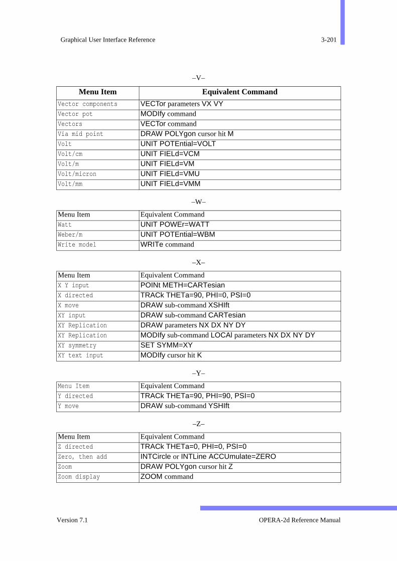
Graphical User Interface Reference 3-201
–V–
–W–
–X–
–Y–
–Z–
Menu Item Equivalent Command Vector components VECTor parameters VX VY Vector pot MODIfy command Vectors VECTor command Via mid point DRAW POLYgon cursor hit M Volt UNIT POTEntial=VOLT Volt/cm UNIT FIELd=VCM Volt/m UNIT FIELd=VM Volt/micron UNIT FIELd=VMU Volt/mm UNIT FIELd=VMM
Menu Item Equivalent Command Watt UNIT POWEr=WATT Weber/m UNIT POTEntial=WBM Write model WRITe command
Menu Item Equivalent Command X Y input POINt METH=CARTesian X directed TRACk THETa=90, PHI=0, PSI=0 X move DRAW sub-command XSHIft XY input DRAW sub-command CARTesian XY Replication DRAW parameters NX DX NY DY XY Replication MODIfy sub-command LOCAl parameters NX DX NY DY XY symmetry SET SYMM=XY XY text input MODIfy cursor hit K
Menu Item Equivalent Command Y directed TRACk THETa=90, PHI=90, PSI=0 Y move DRAW sub-command YSHIft
Menu Item Equivalent CommandZ directed TRACk THETa=0, PHI=0, PSI=0 Zero, then add INTCircle or INTLine ACCUmulate=ZERO Zoom DRAW POLYgon cursor hit Z Zoom display ZOOM command
Version 7.1 OPERA-2d Reference Manual
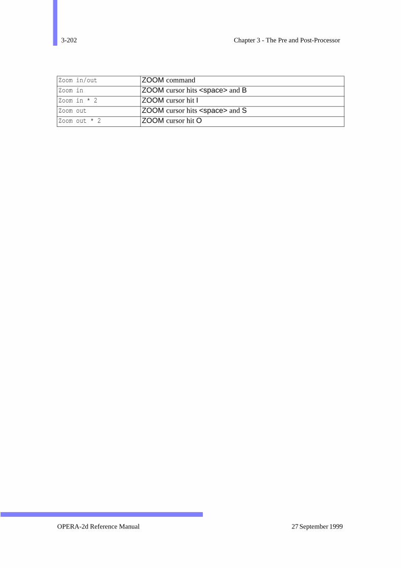
3-202 Chapter 3 - The Pre and Post-Processor
Zoom in/out ZOOM command Zoom in ZOOM cursor hits <space> and B Zoom in * 2 ZOOM cursor hit I Zoom out ZOOM cursor hits <space> and S Zoom out * 2 ZOOM cursor hit O
OPERA-2d Reference Manual 27 September 1999

INDEX
Symbols! 2-12!! 2-20#
free format variables 2-22user variables 2-25
$ ASK 2-29$ ASSIgn 2-31$ BACKspace 2-31$ CD 2-32$ CLOSe 2-29$ COMInput 2-28$ CONStant 2-25, 3-10$ DO-loops 2-23$ ELIF 2-24$ ELSE 2-24$ END 2-25$ FOR-each loops 2-24$ FORMat 2-30$ IF 2-24$ OPEN 2-29$ OS 2-32$ PARAmeter 2-25, 3-10$ PAUSe 2-29$ PROMpt 2-29$ READ 2-30$ STRIng 2-25$ WHILE-loops 2-24$ WRITe 2-30$ABORT, $SKIP 2-20$ASSIgn
see $ ASSIgn
$-commands 2-23$VFDIR
see VFDIR%INT, %REAL, %EXPR 2-17%VFDIR%
see VFDIR, , comma 2-13/ , comment 2-34;, semicolon 2-16|, command separator 2-34’, quotation mark 2-17
-A-abbreviation 2-11, 2-16ac 3-17adaptive refinement options 3-160amplitude 3-17analysis options 3-159angle
region parameter 3-45system variable 3-12, 3-13
anisotropy 3-21APPEnd command 3-19ARC sub-command of DRAW 3-53AREA 3-10, 3-11, 3-15, 3-117
in MODIfy command 3-131, 3-139area
printing 3-146Area integral 3-117arrow keys 2-2, 2-4ASK
see $ ASK
Version 7.1 OPERA-2d Reference Manual
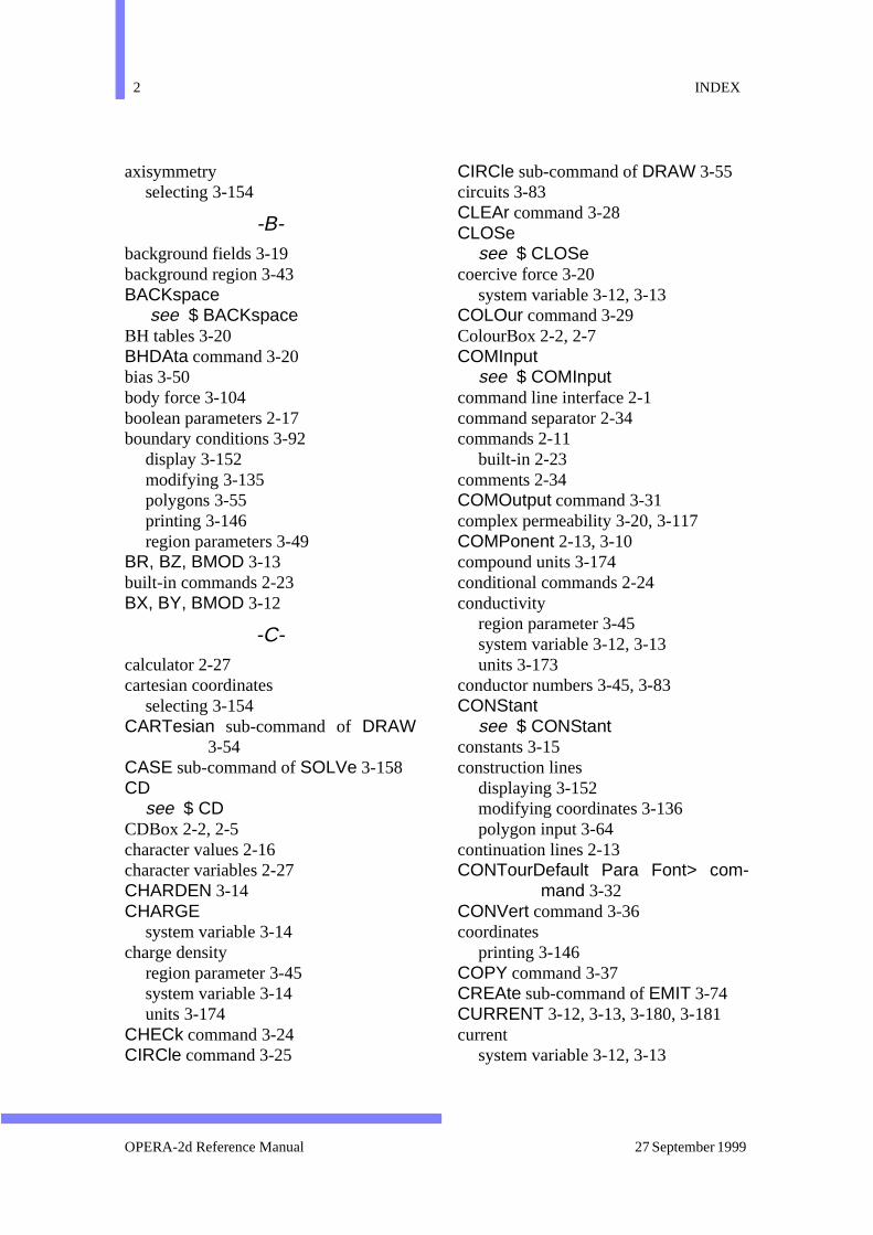
2 INDEX
axisymmetryselecting 3-154
-B-background fields 3-19background region 3-43BACKspace
see $ BACKspaceBH tables 3-20BHDAta command 3-20bias 3-50body force 3-104boolean parameters 2-17boundary conditions 3-92
display 3-152modifying 3-135polygons 3-55printing 3-146region parameters 3-49
BR, BZ, BMOD 3-13built-in commands 2-23BX, BY, BMOD 3-12
-C-calculator 2-27cartesian coordinates
selecting 3-154CARTesian sub-command of DRAW
3-54CASE sub-command of SOLVe 3-158CD
see $ CDCDBox 2-2, 2-5character values 2-16character variables 2-27CHARDEN 3-14CHARGE
system variable 3-14charge density
region parameter 3-45system variable 3-14units 3-174
CHECk command 3-24CIRCle command 3-25
CIRCle sub-command of DRAW 3-55circuits 3-83CLEAr command 3-28CLOSe
see $ CLOSecoercive force 3-20
system variable 3-12, 3-13COLOur command 3-29ColourBox 2-2, 2-7COMInput
see $ COMInputcommand line interface 2-1command separator 2-34commands 2-11
built-in 2-23comments 2-34COMOutput command 3-31complex permeability 3-20, 3-117COMPonent 2-13, 3-10compound units 3-174conditional commands 2-24conductivity
region parameter 3-45system variable 3-12, 3-13units 3-173
conductor numbers 3-45, 3-83CONStant
see $ CONStantconstants 3-15construction lines
displaying 3-152modifying coordinates 3-136polygon input 3-64
continuation lines 2-13CONTourDefault Para Font> com-
mand 3-32CONVert command 3-36coordinates
printing 3-146COPY command 3-37CREAte sub-command of EMIT 3-74CURRENT 3-12, 3-13, 3-180, 3-181current
system variable 3-12, 3-13
OPERA-2d Reference Manual 27 September 1999
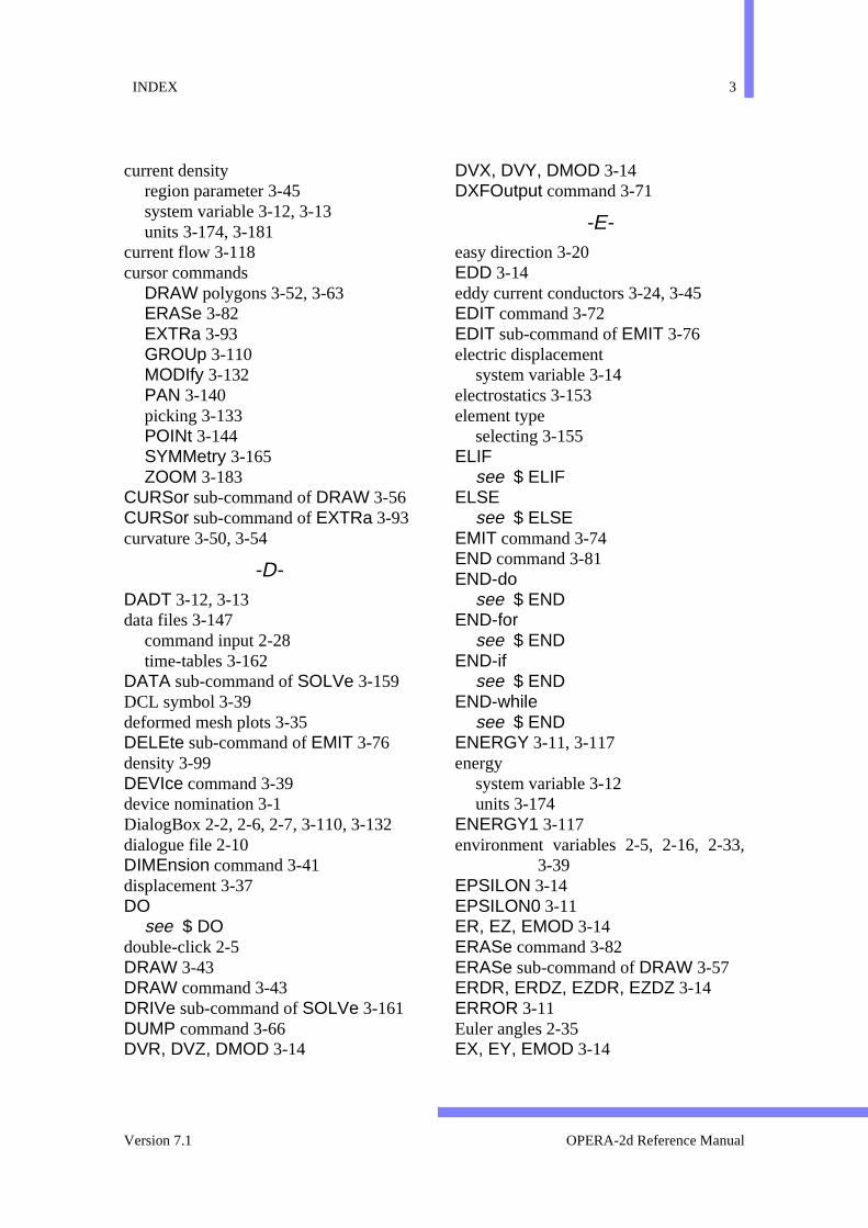
INDEX 3
,
current densityregion parameter 3-45system variable 3-12, 3-13units 3-174, 3-181
current flow 3-118cursor commands
DRAW polygons 3-52, 3-63ERASe 3-82EXTRa 3-93GROUp 3-110MODIfy 3-132PAN 3-140picking 3-133POINt 3-144SYMMetry 3-165ZOOM 3-183
CURSor sub-command of DRAW 3-56CURSor sub-command of EXTRa 3-93curvature 3-50, 3-54
-D-DADT 3-12, 3-13data files 3-147
command input 2-28time-tables 3-162
DATA sub-command of SOLVe 3-159DCL symbol 3-39deformed mesh plots 3-35DELEte sub-command of EMIT 3-76density 3-99DEVIce command 3-39device nomination 3-1DialogBox 2-2, 2-6, 2-7, 3-110, 3-132dialogue file 2-10DIMEnsion command 3-41displacement 3-37DO
see $ DOdouble-click 2-5DRAW 3-43DRAW command 3-43DRIVe sub-command of SOLVe 3-161DUMP command 3-66DVR, DVZ, DMOD 3-14
DVX, DVY, DMOD 3-14DXFOutput command 3-71
-E-easy direction 3-20EDD 3-14eddy current conductors 3-24, 3-45EDIT command 3-72EDIT sub-command of EMIT 3-76electric displacement
system variable 3-14electrostatics 3-153element type
selecting 3-155ELIF
see $ ELIFELSE
see $ ELSEEMIT command 3-74END command 3-81END-do
see $ ENDEND-for
see $ ENDEND-if
see $ ENDEND-while
see $ ENDENERGY 3-11, 3-117energy
system variable 3-12units 3-174
ENERGY1 3-117environment variables 2-5, 2-16, 2-33
3-39EPSILON 3-14EPSILON0 3-11ER, EZ, EMOD 3-14ERASe command 3-82ERASe sub-command of DRAW 3-57ERDR, ERDZ, EZDR, EZDZ 3-14ERROR 3-11Euler angles 2-35EX, EY, EMOD 3-14
Version 7.1 OPERA-2d Reference Manual

4 INDEX
,
EXDX, EXDY, EYDX, EYDY 3-14expressions 2-15, 3-10, 3-16EXTErnal circuit command 3-83EXTRa command 3-91
-F-face properties 3-49
printing 3-146field averaging 3-26, 3-122, 3-124,
3-126, 3-143, 3-156field gradient
system variable 3-12, 3-13, 3-14field point coordinates 3-12, 3-13, 3-14field strength
system variable 3-12, 3-13, 3-14units 3-173
field typeselecting 3-155
field valuesalong circular arcs 3-26along lines 3-126along region sides 3-142area integrals 3-117at points 3-144contours 3-33line integrals 3-121, 3-123vectors 3-176
FileBox 2-2, 2-4, 2-7filenames 2-16files
BH 3-21command input 3-28, 3-31data 3-147, 3-182dialogue 3-27, 3-126, 3-143, 3-146,
3-177mesh 3-129, 3-147, 3-182results 3-19, 3-147, 3-182
FINIsh sub-command of DRAW 3-57FLUX 3-11, 3-117flux density
system variable 3-12, 3-13units 3-173
FORsee $ FOR
force 3-122, 3-124system variable 3-12, 3-13, 3-14units 3-174
force densitysystem variable 3-12, 3-13
FORMatsee $ FORMat
Fourier series 3-112FR, FZ 3-13, 3-14, 3-117free format input 2-22FREQ 3-11frequencies 3-158FX, FY 3-12, 3-14, 3-117, 3-122, 3-124FZ 3-122, 3-124
-G-gap regions 3-43GO conductor 3-85GRAPh command 3-106graphical user interface 2-1graphs 3-27, 3-126, 3-143grid 3-62, 3-136GROUp command 3-109GUI 2-1, 3-185
-H-hard magnetic materials 3-20HARMonics command 3-112HCR, HCZ 3-13HCX, HCY 3-12HDB 3-12, 3-13help character 2-12HELP command 3-116hide menus 2-8homogeneity 3-26, 3-33, 3-126, 3-143
3-144horizontal menu 2-2HR, HZ, HMOD 3-13HRDR, HRDZ, HZDR, HZDZ 3-13HX, HY, HMOD 3-12HXDX, HXDY, HYDX, HYDY 3-12hysteresis 3-20, 3-117
OPERA-2d Reference Manual 27 September 1999
INDEX 5
-I-IF
see $ IFinductance 3-84INTArea command 3-117INTCircle command 3-121INTEGRAL 3-11, 3-117, 3-122, 3-124integral
area 3-117circular arc 3-121current 3-118, 3-119flux 3-118, 3-119force 3-118, 3-119, 3-120, 3-122,
3-124Fourier coefficients 3-113Legendre coefficients 3-114line 3-123power 3-118, 3-119stored energy 3-118, 3-119, 3-120torque 3-122, 3-124
integral fields 3-156INTLine command 3-123Isotropic materials 3-21
-J-J 3-12, 3-13, 3-181
-L-Legendre polynomials 3-112length
units 3-173length of circuit 3-86limits 1-3LINE command 3-125line contours 3-34line integral 3-121, 3-123LINE sub-command of DRAW 3-58linear analysis 3-159linear elements 3-155LIST sub-command of EMIT 3-78LOAD sub-command of EXTRa 3-97local coordinate system
modifying 3-139
local coordinatesin COPY command 3-37printing 3-146region parameters 3-48
loops 2-23, 3-21Lorentz force
system variable 3-12, 3-13LR, LZ 3-13LX, LY 3-12
-M-M 3-180, 3-181mass
units 3-174material angle
region parameter 3-45system variable 3-12, 3-13
material code 3-45material properties 3-92, 3-93
electromagnetics 3-45stress analysis 3-93, 3-98thermal analysis 3-93, 3-98
MATErial sub-command of EXTRa 3-98MAXIMUM 3-11, 3-27, 3-127, 3-143Maxwell stress 3-104, 3-122, 3-124menu interface 2-1menu off 2-8menus 2-2mesh
display 3-129, 3-152generation 3-128
MESH command 3-128mesh files 3-147MessageBox 2-2, 2-6, 2-28, 2-29, 2-34MINIMUM 3-11, 3-27, 3-127, 3-143MODIfy command 3-130MU 3-12, 3-13MU0 3-11multiple cases 3-158
-N-narrow gaps 3-44nodally averaged fields see field averag-
ing 3-156
Version 7.1 OPERA-2d Reference Manual

6 INDEX
nodes 3-152non-linear analysis 3-159normal unit vector 3-12, 3-13, 3-14numeric values 2-15numerical variables 2-25NVR, NVZ 3-13, 3-14NVX, NVY 3-12, 3-14
-O-OPEN
see $ OPENopera2.comi 3-1, 3-28Opera2d_PP_n.log 2-10Opera2d_PP_n.lp 2-10, 3-146, 3-177,
3-181operating system commands 2-32OS
see $ OSoutput time 3-158
-P-packing factor 3-21
region parameter 3-20, 3-45PAN command 3-140PARAmeter
see $ PARAmeterParameterBox 2-2, 2-3, 2-7, 3-131, 3-184parameters 2-11, 3-16particle trajectories 3-170, 3-179PAUSe
see $ PAUSeperiodicity conditions 3-50, 3-55, 3-164permeability
region parameter 3-45system variable 3-12, 3-13
permittivityregion parameter 3-45system variable 3-14
perturbation fields 3-19PHASE 3-12, 3-13phase 3-17phase angle
complex permeability 3-20region parameter 3-45
system variable 3-12, 3-13PI 3-11pick operations 3-133picking 2-3pictures 3-150PLOT command 3-141POINt command 3-144point transformation 3-132Poisson's ratio 3-99POLAr sub-command of DRAW 3-58polygons 3-43positional assignments 2-13POT 3-11potential
selecting for solution 3-155system variable 3-11units 3-173
POWER 3-12, 3-13, 3-117power
system variable 3-12, 3-13units 3-174
PRINt command 3-146program sizes 1-3PROMpt
see $ PROMptprompting
for parameter values 2-20in command input files 2-29
PSHIft sub-command of DRAW 3-59
-Q-Q 3-180, 3-181quadratic elements 3-155quadrilateral regions 3-43QUIT sub-command of DRAW 3-59QUIT sub-command of EMIT 3-79QUIT sub-command of EXTRa 3-101
-R-R, Z 3-13, 3-14, 3-180radio-buttons 2-6READ
see $ READREAD command 3-147
OPERA-2d Reference Manual 27 September 1999
INDEX 7
1
4
READ sub-command of EMIT 3-79RECOnstruct command 3-149reflection 3-37region coordinates 3-46region corners 3-132region matching 3-166region properties
printing 3-146REGIONS 3-15regions 3-43relative permeability
system variable 3-12, 3-13relative permittivity
system variable 3-14replications
copying regions 3-37printing 3-146region parameters 3-48
restart solutions 3-160results files 3-147RETURN conductor 3-85RLOAD, ZLOAD 3-104rotating machines
see gap regionsrotating machines velocity 3-160rotation 3-37RSHIft sub-command of DRAW 3-60rubber-box 2-3
-S-saturation magnetization 3-20SAVE sub-command of EXTRa 3-102SCALE 3-11scale factor 3-158scaling 3-31scroll bars 2-4, 2-7selecting 2-2SET command 3-153SHAPe codes 3-43, 3-45shear modulus 3-99SIGMA 3-12, 3-13slider bars 2-7snap to grid 3-62, 3-136SOLVe command 3-157
space charge analysis options 3-160space charge beam analysis
magnetic field tables 3-182specific heat capacity 3-99SPICE type data 3-88steady-state ac
post-processing 3-17STORe sub-command of EMIT 3-80stored energy
system variable 3-13, 3-14units 3-174
stress analysisload tables 3-104, 3-182loads and constraints 3-92, 3-96, 3-10material properties 3-93, 3-98solution tables 3-148
stress analysis options 3-161STRIng
see $ STRIngsubdivision 3-50superscripts 2-17symbol contours 3-35SYMMetry
boundary conditions 3-50, 3-55, 3-16eddy current conductors 3-45of problem (XY or AXI) 3-154
SYMMetry command 3-164system variables 3-10system variables for the VIEW command
3-180
-T-TABLe sub-command of EXTRa 3-103tables
creating 3-92post-processing 3-11reading 3-148writing 3-182
tangential unit vector 3-12, 3-13, 3-14TEST command 3-166text function 2-17text output modes 2-28thermal analysis
boundary conditions 3-92
Version 7.1 OPERA-2d Reference Manual

8 INDEX
heat source tables 3-104material properties 3-93, 3-98solution tables 3-148temperature tables 3-182
thermal conductivity 3-99thermal expansion integral 3-99time average 3-17time derivative 3-12, 3-13time of flight 3-180, 3-181TIME parameter 3-17timers 2-7time-table files 3-162timetables 3-162TITLe command 3-168titles 3-27, 3-127, 3-143, 3-168TOF 3-180, 3-181tolerance 3-128TORQUE 3-12, 3-14, 3-122, 3-124torque 3-122, 3-124
system variable 3-12, 3-14TRACk command 3-169trajectories 3-169, 3-178transient drive functions 3-161transient time step options 3-160TTIME 3-11TVR, TVZ 3-13, 3-14TVX, TVY 3-12, 3-14
-U-UNDO command 3-172UNITs command 3-173user constants 3-15user interface 2-1user parameters 3-16user variables 2-25, 3-15
-V-variables 3-15
character 2-27in expressions 2-15, 2-16in free format input 2-22numerical 2-25
VECTor command 3-176VELOCITY 3-12, 3-13
velocityregion parameter 3-45system variable 3-12, 3-13
VELX 3-180, 3-181VELY 3-180, 3-181VELZ 3-180, 3-181vertical menu 2-2VFDIR 2-6, 2-16, 2-33VFGRAPHICS 3-39VFINV 3-40VFWINDOWH 3-40VFWINDOWW 3-40VIEW command 3-178Voltage driven circuits 3-83VOLUME 3-10, 3-13, 3-14, 3-15, 3-117volume
printing 3-146system variable 3-13, 3-14
VX 3-10VX and VY 2-13VY 3-10
-W-WHILe
see $ WHILeWRITe
see $ WRITeWRITe command 3-182
-X-X, Y 3-12, 3-14, 3-15, 3-180, 3-181XLOAD, YLOAD 3-104XSHIft sub-command of DRAW 3-60
-Y-Young's modulus 3-99YSHIft sub-command of DRAW 3-61
-Z-zone contours 3-35ZOOM command 3-183ZOOM sub-command of DRAW 3-61ZOOM sub-command of EMIT 3-80ZOOM sub-command of EXTRa 3-105
OPERA-2d Reference Manual 27 September 1999


![Genius Guide - Illustrate with Photoshop 2012 - Volume 1[ChrisArmand] draw drawing digital painting 2d.pdf](https://static.documents.pub/doc/80x56/55cf9b42550346d033a5551d/genius-guide-illustrate-with-photoshop-2012-volume-1chrisarmand-draw.jpg)


