56
DOE/ID-11337 Revision 3 Operable Unit 3-14, Tank Farm Soil and INTEC Groundwater Operation and Maintenance Plan June 2015

DOE/ID-11337 Revision 3
Operable Unit 3-14, Tank Farm Soil and INTEC Groundwater Operation and Maintenance Plan
June 2015


DOE/ID-11337 Revision 3
Project No. 23512
Operable Unit 3-14, Tank Farm Soil and INTEC Groundwater Operation and Maintenance Plan
June 2015
Prepared for the U.S. Department of Energy
DOE Idaho Operations Office


iii
ABSTRACT
This revised Operation and Maintenance Plan lists the regulatory requirements to meet and guidance to follow for the operation and maintenance of the components for use in the implementation of the Operable Unit 3-14 selected remedy as detailed in the Record of Decision for Tank Farm Soil and INTEC Groundwater, Operable Unit 3-14. The activities described in this plan include (1) routine inspections of the recharge control zone asphalt-paved areas, the storm water collection system (concrete-lined and high-density-polyethylene-lined drainage ditches, culverts, and the lift station), and evaporation pond; (2) maintenance of equipment/material; (3) documentation and reporting requirements; and (4) organizational responsibilities. Inspection, monitoring, and maintenance are intended to assure functionality of the selected remedy.

iv

v
CONTENTS
ABSTRACT ................................................................................................................................................. iii
ACRONYMS .............................................................................................................................................. vii
1. INTRODUCTION ........................................................................................................................... 1-1
1.1 Background ........................................................................................................................ 1-1
2. REQUIREMENTS AND RESPONSIBILITIES ............................................................................. 2-1
3. OU 3-14 REMEDY COMPONENTS ............................................................................................. 3-1
3.1 Asphalted Areas ................................................................................................................. 3-3
3.2 Concrete Areas ................................................................................................................... 3-4
3.3 Water Collection System Ditches and Culverts ................................................................. 3-4
3.4 Olive Avenue Lift Station .................................................................................................. 3-4
3.5 Evaporation Pond Liner and Perimeter .............................................................................. 3-5
3.6 Evaporation Pond Leak Detection System ......................................................................... 3-6
3.7 Building Gutters and Downspouts ...................................................................................... 3-7
3.8 Telemetry Systems at Perched Water Monitoring Wells ................................................... 3-7
3.9 Monitoring Wells ............................................................................................................... 3-8
4. INSPECTION, MAINTENANCE, MONITORING, AND SURVEY ........................................... 4-1
4.1 Component Inspections ...................................................................................................... 4-1
4.1.1 Inspection Forms .............................................................................................. 4-1
4.1.2 Inspection Frequencies ..................................................................................... 4-1
4.1.3 Contingency Inspections .................................................................................. 4-2
4.2 Lift Station and Leak Detection Control Panels ................................................................. 4-3
4.2.1 Annual System Checks .................................................................................... 4-3
4.2.2 High-Water Indicators ...................................................................................... 4-3
4.3 Maintenance ....................................................................................................................... 4-3
4.4 Monitoring Activities ......................................................................................................... 4-4
4.5 Radiological Surveys .......................................................................................................... 4-5
4.6 Water Diverted to the Evaporation Pond ............................................................................ 4-5
5. ANNUAL OPERATIONS AND MAINTENANCE REPORT ...................................................... 5-1
6. RESPONSIBILITIES ...................................................................................................................... 6-1
6.1 DOE-ID Waste Area Group 3 Project Manager ................................................................. 6-1
6.2 Environmental Restoration Project Facility Manager ........................................................ 6-1
6.3 OU 3-14 System Engineer .................................................................................................. 6-1
6.4 Tank Farm Area Owner ...................................................................................................... 6-2

vi
6.5 INTEC Operations Facility Manager ................................................................................. 6-2
6.6 Radiological Control Manager ........................................................................................... 6-3
7. RECORDS ....................................................................................................................................... 7-1
8. REFERENCES ................................................................................................................................ 8-1
Appendix A—Technical Response Team ................................................................................................. A-1
Appendix B—Operable Unit 3-14 Forms To Document Scheduled Component Inspections and System Checks ......................................................................................................................... B-1
FIGURE
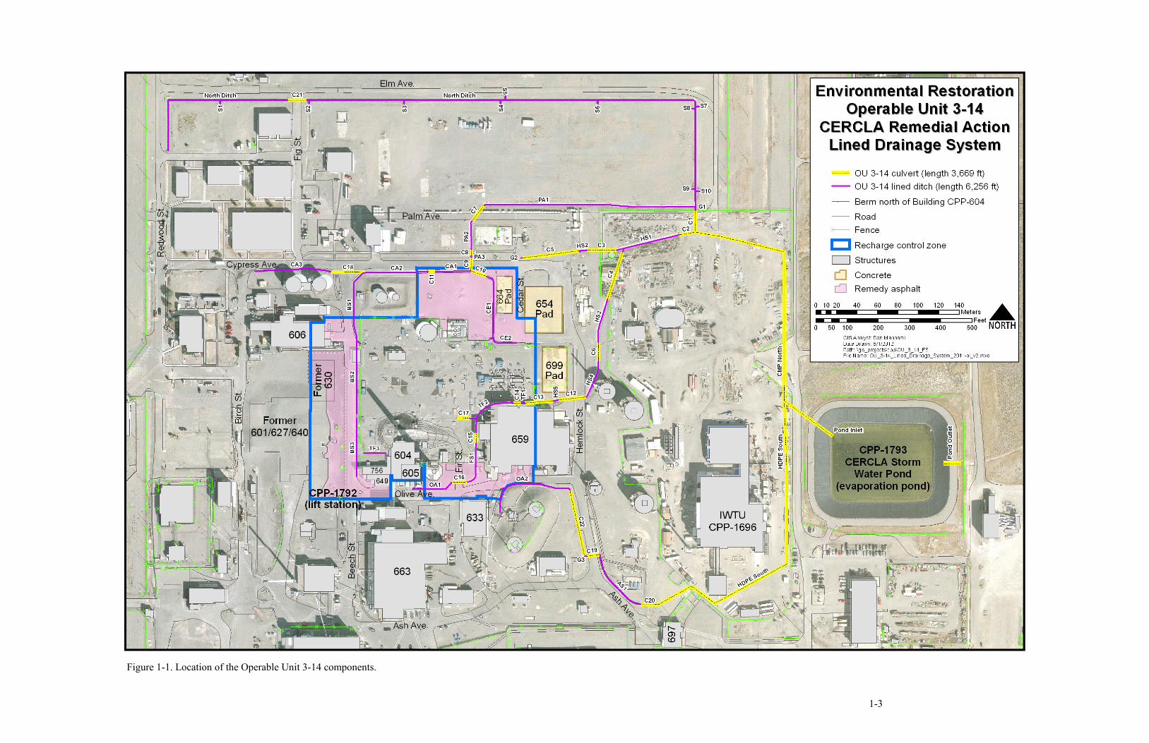
1-1. Location of the Operable Unit 3-14 components ............................................................................ 1-3
TABLES
2-1. Requirements and responsibilities for the Operable Unit 3-14 selected remedy ............................. 2-1
3-1. List of selected remedy components ............................................................................................... 3-1
4-1. List of forms used to document scheduled component inspections and system checks .................. 4-1
4-2. Inspection frequencies for remedy components .............................................................................. 4-2
vii
ACRONYMS
CERCLA Comprehensive Environmental Response, Compensation, and Liability Act
DOE-ID Department of Energy Idaho Operations Office
EDMS Electronic Document Management System
ERP Environmental Restoration Project
ET/CB evaportranspiration cap with capillary biobarrier
FFA/CO Federal Facility Agreement and Consent Order
HDPE high-density polyethylene
INTEC Idaho Nuclear Technology and Engineering Center
O&M operation and maintenance
OU operable unit
RCZ recharge control zone
ROD Record of Decision
TFIA Tank Farm Interim Action
TRT Technical Response Team

viii

1-1
Operable Unit 3-14, Tank Farm Soil and INTEC Groundwater Operation and Maintenance Plan
1. INTRODUCTION
In accordance with the Federal Facility Agreement and Consent Order (FFA/CO) (DOE-ID 1991) Action Plan, the U.S. Department of Energy Idaho Operations Office (DOE-ID) submits this remedial design/remedial action Operation and Maintenance (O&M) Plan for the remediation of the tank farm soil and Idaho Nuclear Technology and Engineering Center (INTEC) groundwater under Operable Unit (OU) 3-14. The O&M in this plan—as part of the Comprehensive Environmental Response, Compensation, and Liability Act (CERCLA) process—will proceed in accordance with the Record of Decision for Tank Farm Soil and INTEC Groundwater, Operable Unit 3-14 (ROD) (DOE-ID 2007), signed on May 14, 2007.
This O&M Plan revision lists the regulatory requirements to meet and guidance to follow for the O&M of the components for use in the implementation of the OU 3-14 selected remedy. The activities described in this plan include (1) routine inspections of the recharge control zone (RCZ) asphalt-paved areas, the storm water collection system (concrete-lined and high-density-polyethylene (HDPE) -lined drainage ditches, metal and HDPE culverts, and the lift station), and evaporation pond; (2) maintenance of equipment/material; (3) documentation and reporting requirements; and (4) organizational responsibilities. Inspection, monitoring, and maintenance are intended to assure functionality of the selected remedy.
This O&M Plan lists the components in place as of the date of this document revision. Additional components and modifications to existing components will take place in phases, as identified by the project schedule and summarized below:
Phase I—Installation of a low-permeability pavement over the RCZ outside the tank farm fence before Tank Farm Facility closure. Implementation of recharge and run-off controls (installation of automated monitoring equipment in perched water monitoring wells, installation of building gutters and downspouts, lining additional drainage ditches).
Phase II—Installation of low-permeability pavement over the north, central, and south tank farm.
Phase III—Installation of the final cover over the north tank farm and the evaportranspiration cap with capillary biobarrier (ET/CB) over the central and south tank farm after Tank Farm Facility closure.
A detailed description of these components, including a schedule for installation and costs for O&M, is contained in the Operable Unit 3-14, Tank Farm Soil and INTEC Groundwater Remedial Design/Remedial Action Work Plan (DOE-ID 2013). This O&M plan will be updated, as necessary, when conditions change (e.g., new remedy components are installed, existing components are modified, changing facility conditions affect the remedy).
1.1 Background
In the OU 3-13 ROD (DOE-ID 1999), the selected remedy for the tank farm soils and INTEC groundwater was deferred pending further characterization and coordination of any proposed remedial actions with the Idaho High-Level Waste & Facilities Disposition Environmental Impact Statement

1-2
(DOE 2002) and a separate remedial investigation/feasibility study, Proposed Plan, and ROD were prepared for the tank farm soils under OU 3-14. These documents were finalized May 2006, August 2006, and May 2007, respectively. Under OU 3-13, an interim action was selected and implemented to provide protection to the groundwater, which included institutional controls with surface water control. This interim action, named Tank Farm Interim Action (TFIA), was designated as Group 1 within OU 3-13. The Group 1 soils are located within the tank farm fence and adjacent to the process equipment waste evaporator building. Implementation of this interim action began in 2000 and was completed in 2004. Components installed included the following:
• Evaporation pond (CPP-1793) with double liner, perimeter fencing, and leak detection system
• Concrete-lined ditches and culverts in and around the tank farm extending to the evaporation pond
• Olive Avenue lift station (CPP-1792)
• Asphalt coverings over selected areas.
The concrete-lined ditches and culverts were designed to receive and transport storm water run-off from the tank farm and surrounding area to the evaporation pond (see Figure 1-1 for component locations).
Inspection, monitoring, and maintenance activities for the TFIA components continued under the OU 3-13, Group 1, O&M Plan (DOE-ID 2006) until finalization of the OU 3-14 Remedial Design/Remedial Action Work Plan (DOE-ID 2008a),a which, as an attachment, included Revision 0 of this O&M Plan. The components installed under OU 3-13 were incorporated into the OU 3-14 selected remedy and are maintained/managed under this plan. Revision 1 of the OU 3-14 O&M Plan was prepared after completion of the Phase I drainage ditch upgrades. Revision 2 has been prepared after completion of Phase I of the selected remedy. Revision 3 modified the characterization criteria for discharging water to the OU 3-14 drainage system by allowing either sampling and analysis or documented process knowledge to be used in the preparation of the hazardous waste determination.
a. The Work Plan was revised in 2013 (DOE-ID 2013).
1-3
Figure 1-1. Location of the Operable Unit 3-14 components.

1-4

2-1
2. REQUIREMENTS AND RESPONSIBILITIES
The project’s requirements and responsibilities for maintaining the OU 3-14 selected remedy components are outlined in Table 2-1.
Table 2-1. Requirements and responsibilities for the Operable Unit 3-14 selected remedy.
General
Maintain the Operable Unit 3-14 selected remedy components (1) for worker and environment protection, (2) to transport surface water run-off and discharges away from the recharge control zone (e.g., to the lined evaporation pond, Idaho Nuclear Technology and Engineering Center service waste system, or evaporation), and (3) to reduce water infiltration from anthropogenic discharges.
Specific
Item Description
1 Perform and document fiscal year quarterly inspections on remedy components
2 Perform and document annual system checks on the Olive Avenue lift station
3 Perform and document annual system checks on the evaporation pond leak detection system
4 Perform necessary maintenance on system components
5 Prepare and submit an annual operations report
6 Notify regulators of identified deficiencies during Agency conference calls
Subsequent sections of the O&M Plan contain information for use in support of meeting the listed requirements and responsibilities.

2-2

3-1
3. OU 3-14 REMEDY COMPONENTS
This section contains descriptions and functions of the components of the selected remedy. Table 3-1 contains a list of selected remedy components with a brief description and location of each. Further details of selected remedy components are contained in the component drawings included in Appendix A of the Remedial Action Report for the Tank Farm Interim Action, WAG 3, OU 3-13, Group 1, Tank Farm Soils (DOE-ID 2005) and Appendix A of the Operable Unit 3-14, Tank Farm Soil and INTEC Groundwater Remedial Design/Remedial Action Work Plan (DOE-ID 2013). Both documents are available in the Electronic Document Management System (EDMS) and the Administrative Record. This O&M Plan contains information on remedy components that have been installed and/or expanded and will be revised during the remedy implementation and O&M phases to reflect changes in components or procedures (EPA 2001).
Table 3-1. List of selected remedy components (see Figure 1-1). Component Description and Location
Phase I asphalt Asphalt located within the recharge control zone but outside the tank farm to include parts of Beech, Fir, and Cedar Streets and most of Olive Avenue (see Figure 1-1)
664 pad Concrete pad north of the tank farm 4-pack 654 pad Southwest corner of concrete pad within the recharge control zone northwest of the
tank farm 605 gutter Gutter and downspouts on the south side of CPP-605 606 gutter Gutter and downspouts on the south side of CPP-606 649 downspout Downspout on the south side of CPP-649 659 gutter Gutter and downspout on the north side of CPP-659 1773 gutter Gutter and downspout on the south side of CPP-1773 North ditch HDPE-lined drainage ditch on the north side of INTEC, south of Elm Avenue,
contains 10 sheet flow collector drains (S1-S10) (receive surface water run-off at low points along the north ditch)
Control panel Control panel for the CPP-1792 lift station mounted on the south wall of Building CPP-649
Lift station CPP-1792 that contains two water transfer pumps beneath the corner of Beech Street and Olive Avenue
Pond liner HDPE liner covering the evaporation pond located east of INTEC Perimeter Area between the evaporation pond and the chain-link fence surrounding the pond Fence/gate Chain-link fence and gate installed around the evaporation pond Flotation rings Flotation rings mounted to the chain-link fence inside the evaporation pond
perimeter (6) Leak detection panel
Evaporation pond leak detection system panel, used to return water that has collected in the pond sump (between the two pond liners) back to the pond surface, located on the west side of the evaporation pond
BS1 Concrete-lined drainage ditch east of Beech Street BS2 Concrete-lined drainage ditch east of Beech Street BS3 Concrete-lined drainage ditch with grated cover east of Beech Street

Table 3-1. (continued).
3-2
Component Description and Location CMP north CMP culvert located between grated inlet G1 and the evaporation pond; contains
two precast concrete manholes HDPE south HDPE culvert with four precast concrete manholes located south and southeast of
IWTU C1 CMP culvert south of Palm Avenue C2 CMP culvert south of Palm Avenue C3 CMP culvert, east end of Hemlock Street C4 CMP culvert east of Hemlock Street C5 CMP culvert near the corner of Cypress Avenue and Hemlock Street C6 CMP culvert east of Hemlock Street C7 CMP culvert beneath Palm Avenue C8 CMP culvert north of Cypress Avenue C9 CMP culvert beneath Cypress Avenue C10 CMP culvert south of Cypress Avenue C11 CMP culvert south of Cypress Avenue C12 CMP culvert beneath Hemlock Street C13 CMP culvert north of CPP-659 C14 CMP culvert north of CPP-659 inside the tank farm C15 CMP culvert west of CPP-659 inside the tank farm C16 CMP culvert beneath Fir Street C17 CMP culvert west of CPP-659 inside the tank farm C18 CMP culvert beneath Beech Street, south of Cypress Avenue C19 CMP culvert beneath Hemlock Street C20 CMP culvert beneath Lodge Pole Street that connects to IWTU drainage C21 CMP culvert located beneath Fig Street at north ditch AS1 HDPE-lined drainage ditch east of Hemlock Street C22 15-in. HDPE culvert west of Hemlock Street CA1 Concrete-lined drainage ditch south of Cypress Avenue CA2 Concrete-lined drainage ditch south of Cypress Avenue CA3 HDPE-lined drainage ditch south of Cypress Avenue CE1 Concrete-lined drainage ditch south of Cypress Avenue CE2 Concrete-lined drainage ditch north of the tank farm FS1 Concrete-lined drainage ditch south of the tank farm G1 Grated inlet at the eastern end of Palm Avenue G2 Catch basin north of Cypress Avenue HS1 Concrete-lined drainage ditch south of Palm Avenue HS2 Concrete-lined drainage ditch near the corner of Cypress Avenue and Hemlock
Street HS3 Concrete-lined drainage ditch east of Hemlock Street
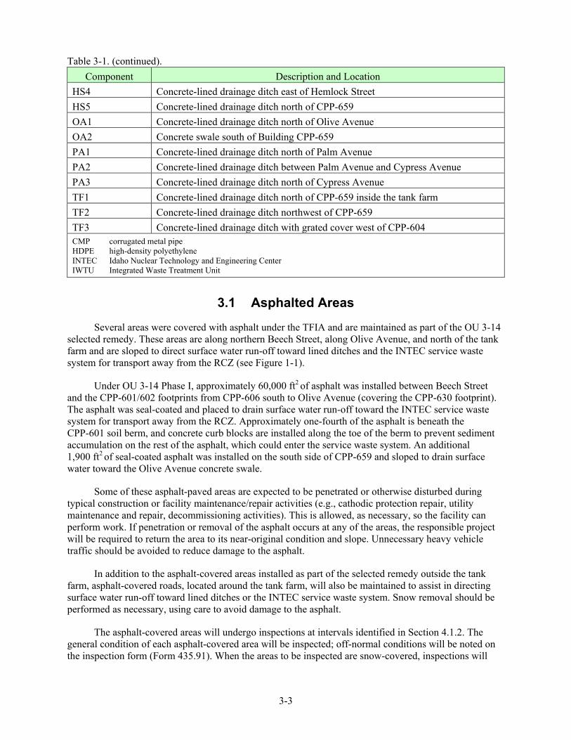
Table 3-1. (continued).
3-3
Component Description and Location HS4 Concrete-lined drainage ditch east of Hemlock Street HS5 Concrete-lined drainage ditch north of CPP-659 OA1 Concrete-lined drainage ditch north of Olive Avenue OA2 Concrete swale south of Building CPP-659 PA1 Concrete-lined drainage ditch north of Palm Avenue PA2 Concrete-lined drainage ditch between Palm Avenue and Cypress Avenue PA3 Concrete-lined drainage ditch north of Cypress Avenue TF1 Concrete-lined drainage ditch north of CPP-659 inside the tank farm TF2 Concrete-lined drainage ditch northwest of CPP-659 TF3 Concrete-lined drainage ditch with grated cover west of CPP-604 CMP corrugated metal pipe HDPE high-density polyethylene INTEC Idaho Nuclear Technology and Engineering Center IWTU Integrated Waste Treatment Unit
3.1 Asphalted Areas
Several areas were covered with asphalt under the TFIA and are maintained as part of the OU 3-14 selected remedy. These areas are along northern Beech Street, along Olive Avenue, and north of the tank farm and are sloped to direct surface water run-off toward lined ditches and the INTEC service waste system for transport away from the RCZ (see Figure 1-1).
Under OU 3-14 Phase I, approximately 60,000 ft2 of asphalt was installed between Beech Street and the CPP-601/602 footprints from CPP-606 south to Olive Avenue (covering the CPP-630 footprint). The asphalt was seal-coated and placed to drain surface water run-off toward the INTEC service waste system for transport away from the RCZ. Approximately one-fourth of the asphalt is beneath the CPP-601 soil berm, and concrete curb blocks are installed along the toe of the berm to prevent sediment accumulation on the rest of the asphalt, which could enter the service waste system. An additional 1,900 ft2 of seal-coated asphalt was installed on the south side of CPP-659 and sloped to drain surface water toward the Olive Avenue concrete swale.
Some of these asphalt-paved areas are expected to be penetrated or otherwise disturbed during typical construction or facility maintenance/repair activities (e.g., cathodic protection repair, utility maintenance and repair, decommissioning activities). This is allowed, as necessary, so the facility can perform work. If penetration or removal of the asphalt occurs at any of the areas, the responsible project will be required to return the area to its near-original condition and slope. Unnecessary heavy vehicle traffic should be avoided to reduce damage to the asphalt.
In addition to the asphalt-covered areas installed as part of the selected remedy outside the tank farm, asphalt-covered roads, located around the tank farm, will also be maintained to assist in directing surface water run-off toward lined ditches or the INTEC service waste system. Snow removal should be performed as necessary, using care to avoid damage to the asphalt.
The asphalt-covered areas will undergo inspections at intervals identified in Section 4.1.2. The general condition of each asphalt-covered area will be inspected; off-normal conditions will be noted on the inspection form (Form 435.91). When the areas to be inspected are snow-covered, inspections will

3-4
not be performed for cracks and potholes (i.e., snow will not be removed to inspect the surface underneath). Small or minor repairs can be performed using commercially available asphalt repair materials (e.g., asphalt chuck filler and asphalt crack filler). Larger repairs will be performed as part of a facility-wide asphalt maintenance activity. The original design specifications of the low-permeability asphalt will be referenced when repairs are performed.
3.2 Concrete Areas Recent decommissioning and demolition activities within the RCZ left two concrete-covered
areas that are used by the selected remedy to prevent water infiltration. In 2004, Building CPP-664 was demolished down to the concrete slab (measuring approximately 6,000 ft2); and, in 2011, Building CPP-654 was also demolished down to the concrete slab. While the entire CPP-664 concrete area is inside the RCZ, only the southwest corner of the CPP-654 concrete area (measuring 50 ft north-south × 36 ft east-west) is within the RCZ (see Figure 1-1). Although the two areas are not sloped, accumulated surface water can flow toward nearby asphalted areas and be collected in lined drainage ditches.
The concrete-covered areas will be inspected at intervals identified in Section 4.1.2. The general condition of each concrete-covered area will be inspected; off-normal conditions will be noted on the inspection form (Form 435.91). When the areas to be inspected are snow-covered, inspections will not be performed for cracks and other deterioration (i.e., snow will not be removed to inspect the surface underneath). Small or minor repairs can be performed using commercially available crack seal/filler materials. Larger repairs may require concrete removal and replacement with asphalt as part of a facility-wide asphalt maintenance activity.
3.3 Water Collection System Ditches and Culverts The water collection system has approximately 3,297 ft of concrete drainage ditches; 2,578 ft of
HDPE-lined drainage ditches; and 2,347 ft of metal culverts and uses an additional 1,215 ft of HDPE culverts to transfer storm-water run-off away from the RCZ (9,437 ft total). Culverts are used to connect sections of lined drainage ditches and ultimately connect the system to the evaporation pond.
The system’s ditches and culverts will be inspected at intervals identified in Section 4.1.2. Inspection results will be documented on Form 435.91 (for components outside the tank farm) or on FRM-585 (for components inside the tank farm). The concrete-lined and HDPE-lined ditches, as well as the culverts associated with the storm water collection system, will be visually inspected to assure that (1) the lined ditches, culverts, and discharge areas are not clogged with sediment and debris that could prevent run-off to the evaporation pond and (2) the integrity of the lined ditches and culverts is satisfactory. Required maintenance shall be managed as detailed in Section 4.3, Maintenance. Deficiencies that prevent the distribution of collected water to the evaporation pond shall be addressed in a timely manner. The ability to allow water to flow to the evaporation pond should be maintained at all times. Removed snow shall not be placed in the lined drainage ditches that are part of the selected remedy (see Figure 1-1).
3.4 Olive Avenue Lift Station The Olive Avenue lift station (CPP-1792) is located beneath the corner of Olive Avenue and
Beech Street. The lift station consists of a buried precast concrete sump that contains two lift pumps with associated piping and liquid-level indicators. The pumps are controlled automatically through a control panel located on the outside wall of Building CPP-649. The lift station is accessed through a metal hatch cover that is flush with the road surface.

3-5
The lift station receives storm water run-off from lined ditches and from an inlet grate and catch basin just northeast and a dry well just southeast of the lift station. When the water level reaches a predetermined pump-on level, the control panel turns on the first pump and the accumulated water is discharged through a pipe (to the east), which discharges the water into the lined drainage ditch near Fir Street. During times of rapid water accumulation, the control panel will activate the second pump.
The lift station area will be inspected at intervals identified in Section 4.1.2. Inspection results will be documented on Form 435.91. An inspection shall include observing and documenting the condition of the system’s pumps, piping, slide rails, water level, hatch doors, and control panel as practical. A system check shall be performed on the lift station components annually and following repairs and upgrade activities to assure proper equipment operation. System check details are contained in Section 4.2.1.
Required repair and maintenance activities shall be performed under the work control system. Deficiencies that prevent the normal operation of the lift station shall be addressed expeditiously. Pump maintenance shall consist of running the pumps until failure followed by replacement. In the event of pump failure, maintenance activities, or loss of power, the water in the lift station sump can be pumped out, using portable equipment, and discharged into the lined ditch FS1 (see Figure 1-1). The responsible Environmental Restoration Project (ERP) facility manager shall maintain a replacement parts inventory that includes a spare pump. The inventory will be inspected at frequencies identified in Section 4.1.2 and documented on the inspection form.
3.5 Evaporation Pond Liner and Perimeter The evaporation pond (CPP-1793) is located east of the INTEC facility (see Figure 1-1) and
consists of two 60-mil HDPE liners: a primary and secondary, with a geonet material between. The bottom of the pond measures approximately 320 × 243 ft and slopes toward a leak collection sump on the far western side. The pond has a single inlet, in the northwest corner, and two outlet discharge pipes on the eastern edge. The liners are held in place along the edge by earthen anchors and along the bottom with sand-filled ballast tubes. The entire pond area is contained within a locked chain-link fence to control access.
The evaporation pond area will be inspected at intervals identified in Section 4.1.2. Inspection results will be documented on Form 435.91. The liner at the perimeter of the pond will be visually inspected for rips and tears, evidence of animal intrusion, weed growth (through the liner or around the perimeter), amount of tension on the liner, environmental degradation, and failure of the liner anchoring system (i.e., the liner pulling away from the pond edges). The perimeter fence, pond inlet, and outlets will also be inspected to assure they are in good condition and contain minimal to no debris. The inspection form may include items used for personnel safety such as availability of personal flotation devices that are determined by safety professionals to be necessary.
The pond inlet, outlets, and bottom (as applicable) will be inspected for sediment and debris. If sediments appear to be impeding inlet flow or if excessive sediment and/or debris have accumulated in the pond’s bottom, maintenance actions will be scheduled for cleaning these areas in a timely manner. Sediment accumulation is not measured. Sediment and debris will be removed as needed, depending upon inspection results. Due to the shallow slope of the remedy’s drainage system, most sediment is deposited in the lined drainage ditches where it is removed quarterly as part of the preventive maintenance action. Sediment and water will be sampled (following the requirements of the project’s Long-Term Monitoring Plan [DOE-ID 2012]) at a frequency and for the analytes described in Section 4.4.

3-6
If the pond is being drained for liner maintenance, sediment and/or debris removal, or removal of excessive storm water volumes, the sediment in the pond will be evaluated and removed, if necessary, as corrective maintenance. No outlets are at an elevation deep enough to empty the pond; therefore, portable pumps will be used to drain the pond, when required. During pond drainage, the flow from the pumps will be managed to assure that the outflow is not eroding the drainage way carrying the flow from the pond.b Prior to discharging this water or cleaning out the sediment, a plan will be developed, which will include water and sediment sampling, analysis, and removal by a pumping or vacuum system. Upon completion of sediment and water sampling and analysis, a waste determination will be performed and documented. Contaminated sediment and water that may not be discharged will be evaluated for management at the Idaho CERCLA Disposal Facility landfill and evaporation pond, respectively, or per the requirements stated in the OU 3-14, Tank Farm Soil and INTEC Groundwater Waste Management Plan (DOE-ID 2008b). If only minor volumes of sediment are found, it will be noted on the inspection form and sampling or removal activities of the sediment will not be performed.
3.6 Evaporation Pond Leak Detection System The evaporation pond is equipped with a leak detection system that monitors the sump water level
and activates a sump pump to return the water from between the liners back into the pond when needed. The system consists of a control panel, sump pump, discharge pipe, flow totalizer, water level indicators, and a sump (located between the primary and secondary pond liners). The control panel contains a digital readout that displays the water level in the sump plus a cumulative hour meter to record the number of hours the sump pump has operated. Located behind the control panel is a totalizer that records the cumulative volume of water pumped from the sump and back into the primary liner of the pond.
The evaporation pond leak detection system area will be inspected at intervals identified in Section 4.1.2. Inspection results will be documented on Form 435.91. A visual inspection will be conducted during two consecutive days (or as close together as possible). On the first day, the control panel, power supply components, totalizer, pump piping, and surrounding area will be checked to assure they are in satisfactory condition. The date, time of day, totalizer reading, hour meter reading, water level, and approximate percent (%) of the pond’s bottom covered by water (e.g., entire pond bottom covered with water is equal to 100% [1.00] covered) will be recorded on the inspection form. On the second day, the date, time, and totalizer reading will be noted. The previous day’s totalizer reading will be subtracted from the current reading to obtain an estimate of a daily leakage volume. The daily leakage volume will then be divided by the percent of the pond’s bottom that is covered by water to determine a leak rate. For example,
Day 1 Totalizer reading = 2,043.4 gal Percent of pond bottom covered by water = 60%
Day 2 Totalizer reading = 2,168.7 gal
Leakage rate = (2,168.7 – 2,043.4)/0.6 = 208.8 gal/day.
b. Since construction in 2003, the maximum volume of water observed in the pond is about 2M gal (spring 2006 and summer
2011), which could be the maximum expected to be pumped out in the event of an emergency or maintenance action. Water would be pumped to the east of the pond and discharged sufficiently far east of INTEC that it would not pose a problem in terms of accelerating downward contaminant transport toward the aquifer. The area of discharge would occur outside the eastern limit of the shallow perched water. Because of the southeasterly dip of the 110-ft sedimentary interbed and the resulting southeasterly shallow perched hydraulic gradient, the evaporation pond is located on the downgradient side of INTEC. Therefore, water discharged to the ground near the evaporation pond will not move westward (updip) toward INTEC.

3-7
The dimensions of the pond’s bottom are 320 ft west-to-east by 243 ft north-to-south. These dimensions can be used to approximate the percent of the pond’s bottom that is covered by water. The depth of the water is not important (as long as the bottom of the pond is completely covered by water, the percent used in the calculation is 100% [1.00]).
The calculated leak rate will then be noted on the inspection form (Form 435.91). The calculated leakage rate represents the volume of water per acre per day. If the leak rate is greater than 6,018 gal/day for the pond (3,400 gal/acre/dayc), the facility manager activates the Technical Response Team (TRT) (see Appendix A).
In addition to conducting inspections, a system check shall be performed on the leak detection system components annually and following repairs and upgrade activities (as necessary) to assure proper equipment operation. System check details are contained in Section 4.2.1.
3.7 Building Gutters and Downspouts
The perimeter of the tank farm contains buildings on the west, south, and east sides. As part of the OU 3-14 selected remedy, existing building gutters and downspouts will be inspected for effectiveness. Currently, Buildings CPP-605, CPP-606, CPP-659, and CPP-1773 have gutters and downspouts and Building CPP-649 has only a downspout.d These components will be inspected at intervals identified in Section 4.1.2, and inspection results will be documented on Form 435.91. Exterior building drainage and capture have been improved as part of the OU 3-14 selected remedy Phase I construction in 2008.
3.8 Telemetry Systems at Perched Water Monitoring Wells
Some perched water monitoring wells are fitted with downhole pressure transducers coupled with wellhead telemetry equipment that will permit frequent data downloads from network computers that have the necessary software. With these components, operators can obtain near-real-time readings of perched water elevations, and any unexpected rise in perched water level can be investigated to determine if a nearby pipeline leak (anthropogenic discharge) has occurred. O&M of these systems and the collection and use of these data are detailed in the Operable Unit 3-14, Tank Farm Soil and INTEC Groundwater Long-Term Monitoring Plan (DOE-ID 2012).
c. The history behind the 3,400-gal/acre/day leak rate is as follows: The approved design for the TFIA Evaporation Pond
allowed for a leakage rate not to exceed 3,400 gal/acre/day, which is equivalent to a 1/8-in. (0.0104-ft) drop in the water level when the pond’s bottom is fully covered. During the initial draft design, the evaporation pond did not have a sump and a pump for collecting and pumping any water that may have leaked through to the primary liner. The original thought was to measure evaporation/leakage using a graduated rod that would be placed down the bank of the pond. By knowing the evaporation rate based on climatic information and using the pan evaporation method nearby and then measuring the water level on the rod, it would be possible to determine leakage and evaporation. The 1/8-in. came from the assumption that it was the smallest difference in water elevation that could be measured using a graduated rod. Although the rod and pan evaporation method were replaced with a pump and sump, the 1/8-in. criterion never went away.
d. Building CPP-649 has no gutters. The roof is surrounded by 2-ft-high parapet walls and has a slight slope that directs rainwater toward exit ports that are connected to the downspout.

3-8
3.9 Monitoring Wells
As part of the OU 3-14 selected remedy, a series of perched water and aquifer monitoring wells are used to monitor water elevations and water quality. These data are used as performance indicators to evaluate the effectiveness of the selected remedy. O&M of these wells and the collection and use of these data are detailed in the Operable Unit 3-14, Tank Farm Soil and INTEC Groundwater Long-Term Monitoring Plan (DOE-ID 2012).

4-1
4. INSPECTION, MAINTENANCE, MONITORING, AND SURVEY
Inspection, monitoring, system check, and maintenance activities are performed on the OU 3-14 components as detailed below.
4.1 Component Inspections Components of the OU 3-14 selected remedy will be inspected regularly to ensure satisfactory
condition and performance. To ensure each component is inspected, the inspector should use an inspection checklist (Form 435.91). The sections below identify the forms to use to document inspections, inspection frequencies, and details on necessary contingency inspections to be performed.
4.1.1 Inspection Forms
Scheduled inspections shall be documented using the forms listed in Table 4-1.
Table 4-1. List of forms used to document scheduled component inspections and system checks.
Form Number Title
435.91 Surface Water Collection System Outside Tank Farm Inspection Form
FRM-508 Annual CPP-1792 Lift Station System Checks Data Sheet
FRM-509 Annual CPP-1793 System Checks for Evaporation Pond Leak Detection Sump Pump Controls Data Sheet
FRM-585 INTEC Inspections Tank Farm Surface Sealed Areas
Form 435.91 is designed to be filled out in the field and completed electronically. It contains the following:
• List of instructions
• List of components to inspect and/or data to record
• Observations and notes section
• Area for inspector and facility owner names, signatures, date
• Area to list and describe photographs taken and attached to the form.
Forms FRM-508 and -509 are designed to be filled out and completed in the field and contain step-by-step instructions to follow, boxes to fill in, a comments section to record observations or findings, and space for the operator and supervisor to print/sign their names and record the date of completion. These forms are completed using an area-specific facility procedure on sewage lift stations.
Forms will be revised as necessary to reflect changing field conditions and/or improvements in the inspection process. The current form revisions are maintained in EDMS under their form numbers. Information contained in the “Observations” section of each form is entered into a maintenance tracking system (see Section 4.3). Appendix B contains examples of each form.
4.1.2 Inspection Frequencies
Table 4-2 lists inspection frequencies and forms to be completed for listed components.

4-2
Table 4-2. Inspection frequencies for remedy components.
Component Frequency Form to be Completed
Tank farm Quarterly FRM-585 Asphalted areas outside tank farm fence Quarterly 435.91 Concrete areas outside tank farm fence Quarterly 435.91 Water collection system ditches and culverts Quarterly 435.91 Olive Avenue lift station Quarterly for visual inspections 435.91 Annually for systems check and
following maintenance activities FRM-508
Spare parts inventory Quarterly 435.91 Evaporation pond liner and perimeter Quarterly 435.91 Evaporation pond leak detection system Quarterly for inspections 435.91 Annually for systems check and
following maintenance activities FRM-509
Building gutters and downspouts Quarterly 435.91
The schedule for the OU 3-14 component inspections is as follows:
QUARTERLY – Quarterly inspections are to be conducted once every fiscal year quarter. The quarters are defined as October–December, January–March, April–June, and July–September. These inspections shall have a minimum of 6 calendar weeks between consecutive inspections. Efforts will be taken to perform one quarterly inspection per year during a precipitation event to allow the inspector to observe drainage flow.
ANNUAL – Annual inspections must be conducted once every fiscal year. These inspections should have a minimum of 11 months and a maximum of 13 months between inspections.
When possible, the quarterly inspections are scheduled to be equally spaced during the year. However, field circumstances (e.g., coordination between projects, maintenance activities, and weather conditions) will alter the actual inspection dates.
4.1.3 Contingency Inspections
Contingency inspections (unscheduled, situation-unique inspections performed upon direction of the facility manager) will be conducted when operational integrity of the system has been or may be threatened. Events that might trigger contingency inspections include severe rainstorms, floods, system failures, or highly unusual events such as tornadoes and earthquakes. As needed, the facility manager activates the TRT (see Appendix A). Issues identified will be entered into a maintenance tracking system for action, and results of contingency inspections will be discussed in the annual operations report (Section 5).

4-3
4.2 Lift Station and Leak Detection Control Panels 4.2.1 Annual System Checks
The OU 3-14 remedy contains two active systems, the Olive Avenue lift station and the evaporation pond leak detection system, as described in Sections 3.3 and 3.5, respectively. To verify operability of the systems and to identify potential maintenance or repair items, system checks are performed annually and after repairs have been completed (as necessary). The forms used to document the system checks are listed in Table 4-1. A preventive maintenance activity is in place and is scheduled to activate during the month of August to perform the system checks.
The systems checks shall be performed by qualified and knowledgeable personnel identified by the INTEC Operations facility manager as directed by the ERP facility manager. Copies of completed forms will be forwarded to the ERP facility manager or designee who shall submit the forms to the Document and Records Service Center for inclusion into the project file/company records system. Annual system checks should be performed during the summer months (June–August) to take advantage of warm temperatures and to allow for time to complete any necessary repairs before winter. Maintenance items identified on the completed forms will be addressed through the work control system. Maintenance items, deficiencies, or concerns noted on the system checks forms are entered into a maintenance tracking system for further monitoring or necessary action (see Section 4.3).
4.2.2 High-Water Indicators
The control panels at the Olive Avenue lift station and the evaporation pond leak detection system are equipped with both visual and audible high-water indicators.e When activated, they indicate that the water level in either the lift station or in the leak detection sump has reached a preset high-water level. Contact information is posted on the front of each control panel which reads:
WAG 3 Operable Unit 3-14
Responsible Organization: Environmental Restoration Contact # - INTEC Shift Supervisor 526-3100
In the event a high-water indicator is activated, observers can use the posted contact information to notify the facility manager and obtain instruction on how to respond to the indicators.
4.3 Maintenance Noted items from inspection forms, system checks, or other activities shall be entered into a
company-maintained computer software-based tracking system. The system shall be used to initiate maintenance activities, document the process, and track maintenance progress through completion.
Items requiring maintenance or repair will be addressed using the work control system (minor maintenance, preventive maintenance, corrective maintenance, etc.); subcontract; or other means deemed appropriate by the facility manager or designee.
e. Utility operators, security personnel, and shift supervisors are present at INTEC 24 hours a day, every day, including
weekends and holidays, and will respond to high-water indicators.

4-4
Due to their configuration, proximity to roadways, and the area’s frequent strong winds, many of the lined ditches accumulate debris, which can interfere with water flow. To respond to this issue, a preventive maintenance activity is in place and is scheduled to activate during the months of April, June, August, and October for debris removal.
In the event the evaporation pond needs to be pumped down for maintenance, requirements for pre-discharge to the surface are given in the Long-Term Monitoring Plan (DOE-ID 2012).
Standard O&M procedures for the OU 3-14 components are integrated into the INTEC documentation to provide proper maintenance for operation. As required, corrective maintenance of equipment and systems will be performed, which consists of unplanned repairs or replacement of system components after they have failed. Examples could be worn-out pumps, leaky pipes, damaged concrete or asphalt, and malfunctioning electronic equipment.
4.4 Monitoring Activities The low-permeability pavement to be expanded over the RCZ is designed to reduce infiltration of
precipitation. To assist in the reduction of water infiltration, monitoring will identify potential leaks of INTEC utilities that release water into the subsurface. Activities will include the preparation of an INTEC facility water balance and the collection and evaluation of perched water wells water elevation data. This information will be used to assist in the identification of anthropogenic losses and elimination of these leaks. The INTEC facility manager(s) will be responsible for utility repairs. Activities shall be performed in a timely manner to help minimize recharge of the perched water zones.
An INTEC facility water balance will be performed per the information and direction contained in the Operable Unit 3-14, Tank Farm Soil and INTEC Groundwater Long-Term Monitoring Plan (DOE-ID 2012).
Perched water elevation data from telemetry systems will be regularly monitored for unusual fluctuations that cannot be attributed to seasonal changes or other natural events. This information, combined with water balance data and other sources of information (e.g., daily facility operations reports), can be used to help locate utility discharges that may be contributing to recharge of the perched water zones.
Sediment and water in the evaporation pond will be sampled for radiological constituents to coincide with remedy performance reporting in the 5-year review. The details of the sediment and water sampling activity are contained on the OU 3-14 Long Term Monitoring Plan (DOE-ID 2012).
In addition, changing conditions may necessitate additional monitoring that is not specifically described in this O&M Plan. For example, unusually high water levels in the evaporation pond may necessitate daily or weekly monitoring of conditions to ensure operability of the system or to assist in the diagnosis of deficiencies. Monitoring will be per the direction of the ERP facility manager, and actions/findings will be documented in the annual operations report.

4-5
4.5 Radiological Surveys Radiological Control personnel, in accordance with Idaho National Laboratory Site radiological
monitoring and control policies, monitor the OU 3-14 lined drainage ditches for radiological contamination or changes in conditions. (Radiological monitoring is not a requirement of this O&M Plan, but changing conditions are documented on inspection forms.) The focus, frequency, and method of this monitoring are determined by the INTEC Radiological Control supervisor, in accordance with the requirements of 10 CFR 835.401 and 10 CFR 835.1102, as implemented at the Idaho National Laboratory Site in PRD-183. Currently, radiological surveys are performed monthly unless ditches are wet or snow-covered. Results are recorded on Form 441.45 and filed in the INTEC Radiological Control office. Radiological surveys are currently not performed or required on any OU 3-14 asphalted areas or within the evaporation pond fenced area.
4.6 Water Diverted to the Evaporation Pond Nonhazardous, nonradiologically regulated waters discharged directly to the ground can contribute
to the recharge of perched water zones. Where possible, these waters will be diverted to the evaporation pond rather than being discharged to the ground. Waters from specific, controlled systems can be directly diverted to the lined ditches without prior approval or notifications. These waters include raw water, fire water, steam condensate water, potable water, demineralized water, and demineralizer system backwash water. These plant waters would not have come into contact with radiologically controlled systems or hazardous waste.
In the proximity of the tank farm drainage system are utility tunnels, sumps, and similar areas that may collect water from events such as storm water run-off or breaks in potable water or fire water lines, in addition to facility activities that may generate occasional wastewater that requires disposal. This water is potentially contaminated due to contact with or the presence of chemical constituents or radionuclides and shall be fully characterized for radiological and chemical constituents before transfer to the OU 3-14 drainage system can take place. Characterization can consist of either sampling and analysis or documented process knowledge. If sampling is required (e.g. adequate process knowledge is unavailable), the water will be sampled in accordance with an ER-approved sampling plan and assessed for constituents potentially contaminating the water (e.g., volatile organic compounds, semivolatile organic compounds, total petroleum hydrocarbon, total metals, and radionuclides). These analytical results and process knowledge will be used by Waste Generator Services to prepare a Waste Determination and Disposition Form (Form 435.39) prior to discharge since the system is not designed to accept water that is a hazardous waste, is not determined to be radiologically regulated, or could otherwise adversely affect the pond system (e.g., liner or impact the OU 3-14 remedy). The Waste Determination and Disposition Form and supporting characterization information for these considerations will be assessed for each wastewater stream before discharge into the OU 3-14 lined ditches. The OU 3-14 facility manager will authorize disposal of all wastewaters to the drainage system contingent on meeting the criteria in this section, and the discharges will be reported in the OU 3-14 annual O&M report.

4-6

5-1
5. ANNUAL OPERATIONS AND MAINTENANCE REPORT
An annual O&M report for the OU 3-14 remedy will be prepared and submitted to the Environmental Protection Agency, Idaho Department of Environmental Quality, and DOE-ID. Topics discussed in the annual report should include:
• A summary of scheduled and contingency inspections performed
• Results of system checks for the Olive Avenue lift station and evaporation pond leak detection system
• Evaporation pond leak detection system monitoring data
• A summary of pond sediment sampling and analysis results
• A summary of groundwater and perched water monitoring results
• A summary of maintenance activities performed
• A summary of anthropogenic water discharges and leaks
• Projected maintenance activities required for the next year
• A summary of water diverted to the evaporation pond and sample results
• A discussion on INTEC facility water balance and perched water elevation data as they relate to the detection of subsurface water discharges
• A summary and interpretations regarding the water balance for the northern INTEC area that include water/wastewater line leaks, water discharges, and northern shallow perched water level changes.

5-2
6-1
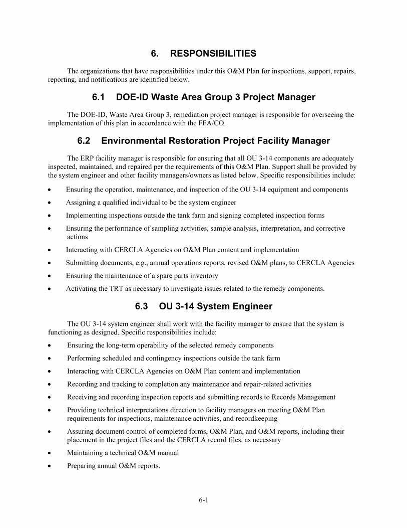
6. RESPONSIBILITIES
The organizations that have responsibilities under this O&M Plan for inspections, support, repairs, reporting, and notifications are identified below.
6.1 DOE-ID Waste Area Group 3 Project Manager
The DOE-ID, Waste Area Group 3, remediation project manager is responsible for overseeing the implementation of this plan in accordance with the FFA/CO.
6.2 Environmental Restoration Project Facility Manager
The ERP facility manager is responsible for ensuring that all OU 3-14 components are adequately inspected, maintained, and repaired per the requirements of this O&M Plan. Support shall be provided by the system engineer and other facility managers/owners as listed below. Specific responsibilities include:
• Ensuring the operation, maintenance, and inspection of the OU 3-14 equipment and components
• Assigning a qualified individual to be the system engineer
• Implementing inspections outside the tank farm and signing completed inspection forms
• Ensuring the performance of sampling activities, sample analysis, interpretation, and corrective actions
• Interacting with CERCLA Agencies on O&M Plan content and implementation
• Submitting documents, e.g., annual operations reports, revised O&M plans, to CERCLA Agencies
• Ensuring the maintenance of a spare parts inventory
• Activating the TRT as necessary to investigate issues related to the remedy components.
6.3 OU 3-14 System Engineer
The OU 3-14 system engineer shall work with the facility manager to ensure that the system is functioning as designed. Specific responsibilities include:
• Ensuring the long-term operability of the selected remedy components
• Performing scheduled and contingency inspections outside the tank farm
• Interacting with CERCLA Agencies on O&M Plan content and implementation
• Recording and tracking to completion any maintenance and repair-related activities
• Receiving and recording inspection reports and submitting records to Records Management
• Providing technical interpretations direction to facility managers on meeting O&M Plan requirements for inspections, maintenance activities, and recordkeeping
• Assuring document control of completed forms, O&M Plan, and O&M reports, including their placement in the project files and the CERCLA record files, as necessary
• Maintaining a technical O&M manual
• Preparing annual O&M reports.

6-2
6.4 Tank Farm Area Owner
The tank farm area owner is responsible for the grounds and systems located within the tank farm. Specific responsibilities include:
• Maintaining the OU 3-14 components within and next to the boundary of the tank farm in accordance with this O&M Plan
• Implementing inspections inside the tank farm by using personnel familiar with the system as constructed and operated
• Submitting completed OU 3-14 forms to the company Document and Records Service Center
• Submitting copies of all completed forms to the ERP facility manager no more than 30 days after completion
• Submitting requests for changes to the O&M Plan, as needed, to the ERP facility manager
• Implementing and coordinating preventive and corrective maintenance activities
• Implementing follow-up inspections after repair or replacement activities
• Administrating subcontracts for performing required maintenance activities
• Maintaining a record of the maintenance activities performed
• Notifying the ERP facility manager if asphalt repairs will not be completed within 30 days of discovery.
6.5 INTEC Operations Facility Manager
The INTEC Operations manager is the facility manager of most roads and grounds inside of INTEC. Additional responsibilities include most buildings and structures inside of INTEC not specifically identified as being the responsibility of another facility manager. Specific responsibilities include:
• Completing system checks of the Olive Avenue lift station and evaporation pond leak detection system
• Implementing follow-up system checks after repair or replacement activities
• Protecting, repairing, and replacing all asphalted surface areas (to include roads) located outside the perimeter of the tank farm that are part of the OU 3-14 remedy as described in the OU 3-14 Remedial Design\Remedial Action Work Plan (DOE-ID 2013)
• Ensuring that instigated or observed activities do not interfere with the operational capability of the drainage system
• Submitting completed forms to the company Document and Records Service Center
• Submitting copies of all forms completed to the ERP facility manager no more than 30 days after completion
• Submitting requested changes to the O&M Plan, as needed, to the ERP facility manager.

6-3
6.6 Radiological Control Manager
The Radiological Control manager has the following responsibilities:
• Performing monthly radiological surveys of OU 3-14 lined ditches located outside the tank farm fence (excluding wet or snow-covered ditches)
• Documenting results of radiological surveys
• Administering requirements as detailed in PRD-183.

6-4

7-1
7. RECORDS
Records will be managed in accordance with MCP-557, “Records Management.”
NOTE: The Records Schedule Matrix, which is discussed in MCP-557, and the applicable facility, organization, program, or project records management plan and records type list provide current information on uniform file codes, disposition authorities, and retention periods for these records.

7-2

8-1
8. REFERENCES
10 CFR 835.401, 2007, “General requirements,” Code of Federal Regulations, Office of the Federal Register, June 2007.
10 CFR 835.1102, 1998, “Control of areas,” Code of Federal Regulations, Office of the Federal Register, November 1998.
DOE, 2002, Idaho High-Level Waste & Facilities Disposition Final Environmental Impact Statement, DOE/EIS-0287, U.S. Department of Energy, September 2002.
DOE-ID, 1991, Federal Facility Agreement and Consent Order for the Idaho National Engineering Laboratory, Administrative Docket No. 1088-06-29-120, U.S. Department of Energy Idaho Operations Office; U.S. Environmental Protection Agency, Region 10; Idaho Department of Health and Welfare, December 4, 1991.
DOE-ID, 1999, Final Record of Decision, Idaho Nuclear Technology and Engineering Center, Operable Unit 3-13, DOE/ID-10660, Rev. 0, U.S. Department of Energy Idaho Operations Office; U.S. Environmental Protection Agency, Region 10; and Idaho Department of Environmental Quality, October 1999.
DOE-ID, 2005, Remedial Action Report for the Tank Farm Interim Action, WAG 3, OU 3-13, Group 1, Tank Farm Soils, DOE/NE-ID-11209, Rev. 0, U.S. Department of Energy Idaho Operations Office, June 2005.
DOE-ID, 2006, Operation and Maintenance Plan for INTEC Operable Unit 3-13, Group 1, Tank Farm Interim Action, DOE/ID-10771, Rev. 4, U.S. Department of Energy Idaho Operations Office, November 2006.
DOE-ID, 2007, Record of Decision for Tank Farm Soil and INTEC Groundwater, Operable Unit 3-14, DOE/ID-11296, Rev. 0, U.S. Department of Energy Idaho Operations Office; U.S. Environmental Protection Agency, Region 10; and Idaho Department of Environmental Quality, May 2007.
DOE-ID, 2008a, Operable Unit 3-14, Tank Farm Soil and INTEC Groundwater Remedial Design/Remedial Action Work Plan, DOE/ID-11333, Rev. 0, U.S. Department of Energy Idaho Operations Office, June 2008.
DOE-ID, 2008b, Operable Unit 3-14, Tank Farm Soil and INTEC Groundwater Waste Management Plan, DOE/ID-11335, Rev. 0, U.S. Department of Energy Idaho Operations Office, June 2008.
DOE-ID, 2012, Operable Unit 3-14, Tank Farm Soil and INTEC Groundwater Long-Term Monitoring Plan, DOE/ID-11334, Rev. 2, U.S. Department of Energy Idaho Operations Office, August 2012.
DOE-ID, 2013, Operable Unit 3-14, Tank Farm Soil and INTEC Groundwater Remedial Design/Remedial Action Work Plan, DOE/ID-11333, Rev. 1, U.S. Department of Energy Idaho Operations Office, October 2013.
EPA, 2001, “Operation and Maintenance in the Superfund Program,” OSWER 9200.1-37FS, EPA 540-F-01-004, U.S. Environmental Protection Agency, May 2001.

8-2
Form 435.39, 2015, “Waste Determination & Disposition Form (WDDF),” Rev. 11, Idaho Cleanup Project, January 2015.
Form 435.91, 2012, “Surface Water Collection System Outside Tank Farm Inspection Form,” Rev. 5, Idaho Cleanup Project, May 2012.
Form 441.45, 2015, “Radiological Survey Report,” Rev. 6, Idaho Cleanup Project, January 2015.
FRM-508, 2007, “Annual CPP-1792 Lift Station System Checks Data Sheet,” Rev. 2, Idaho Cleanup Project, December 2007.
FRM-509, 2007, “Annual CPP-1793 System Checks for Evaporation Pond Leak Detection Sump Pump Controls Data Sheet,” Rev. 1, Idaho Cleanup Project, June 2007.
FRM-585, 2010, “INTEC Inspections Tank Farm Surface Sealed Areas,” Rev. 1, Idaho Cleanup Project, September 2010.
MCP-557, 2014, “Records Management,” Rev. 17, Idaho Cleanup Project, March 2014.
PRD-183, 2013, “Radiological Control Manual,” Rev. 21, Idaho Cleanup Project, September 2013.
A-1
Appendix A
Technical Response Team

A-2

A-3
Appendix A
Technical Response Team
A-1 PURPOSE
This appendix delineates the requirements for the Operable Unit (OU) 3-14 Remedial Action Technical Response Team (TRT). This team will assist operation, maintenance, and monitoring work crews in resolving issues or problems that arise during work execution that cannot be resolved in a timely manner using available resources. The TRT will have the necessary technical resources available to respond quickly and assist the work crews to:
• Ensure safe and compliant work execution
• Reduce downtime
• Provide real-time feedback to field operations
• Assist with on-the-floor decisions regarding work control issues.
A-2 SCOPE
This appendix applies to all personnel performing work within the OU 3-14 remedial action area of responsibility. The TRT will provide timely assistance to supervisors and foremen in determining a course of action when an unanticipated work condition arises. The TRT will assist with facilitating safe work in the OU 3-14 remedial action area of responsibility but will not relieve the supervisor of the responsibility for safe work execution.
A-3 MEMBERSHIP
The TRT typically consists of, but is not limited to, the following disciplines and members:
• TRT lead
• Engineering manager
• Environmental lead
• Project engineer
• System engineer
• Project manager
• Radiological control manager
• Safety manager
• Additional personnel when determined necessary by the TRT lead.

A-4
A-4 RESPONSIBILITIES
The TRT lead, or designee, has the authority to determine what disciplines are necessary on the TRT, including off-shifts and weekends during work execution.
The TRT will be available when work is being performed. Members of the TRT should carry a cell phone/pager (as appropriate), so personnel needing assistance can easily contact them.
The following steps identify the process for activating the TRT:
• Project manager or job supervisor: Contact the TRT lead or alternate if an issue or problem in work execution is identified that cannot be resolved in a timely manner using existing resources
• TRT lead or alternate: Identify the appropriate expertise necessary to resolve the work execution issue(s)
• TRT lead or alternate: In a timely manner (normally within 24 hours), convene a meeting at the job site with the appropriate TRT members and project personnel to determine resolution of the work execution issue(s)
• TRT lead or alternate: Follow through with issue resolution until the project activity is resumed.
NOTE: When guidance is provided by the TRT, specific details should be documented in the field team leader logbook, work package status log, work order change, or other appropriate documentation.
The field team leader, job supervisor, or subcontractor technical representative has the responsibility to remind the work crews of the process to activate the TRT and document the discussion during initial pre-job briefings or following work order changes when revised pre-job briefings are conducted. The pre-job briefing form may be used to document the discussion.

B-1
Appendix B
Operable Unit 3-14 Forms To Document Scheduled Component Inspections and System Checks

B-2

B-3
Appendix B
Operable Unit 3-14 Forms To Document Scheduled Component Inspections and System Checks
Form 435.91 – Surface Water Collection System Outside Tank Farm Inspection Form ......................... B-4
FRM-508 – Annual CPP-1792 Lift Station System Checks Data Sheet................................................... B-8
FRM-509 – Annual CPP-1793 System Checks for Evaporation Pond Leak Detection Sump Pump Controls Data Sheet ................................................................................................. B-10
FRM-585 – INTEC Inspections Tank Farm Surface Sealed Areas ........................................................ B-11

B-4

B-5

B-6

B-7

B-8

B-9

B-10

B-11

B-12


