Operating guide for Pure Photonics ITLA PPCL200 Page 1 of 12 Proprietary and Confidential vB Operating guide for Pure Photonics ITLA PPCL200 Operating guide for Pure Photonics ITLA PPCL200 Operating guide for Pure Photonics ITLA PPCL200 Operating guide for Pure Photonics ITLA PPCL200 Contents Operating guide for Pure Photonics ITLA PPCL200 ....................................................................................... 1 Introduction .............................................................................................................................................. 1 Disclaimer.................................................................................................................................................. 2 Methods of Operation .............................................................................................................................. 3 Graphical User Interface ........................................................................................................................... 3 Line Editor ................................................................................................................................................. 3 Getting started ...................................................................................................................................... 3 Commands ............................................................................................................................................ 4 Running scripts ...................................................................................................................................... 6 RS-232 communication ............................................................................................................................. 6 Electrical interface ................................................................................................................................ 6 Communication protocol ...................................................................................................................... 6 Available MSA registers ........................................................................................................................ 8 Non-MSA registers .............................................................................................................................. 11 Example ............................................................................................................................................... 12 Introduction The Pure Photonics ITLA is a CW (Continuous Wave) Tunable Laser with integrated electronics. The control of the product is through a digital interface. As a user only limited knowledge of the laser operating principle is needed, as the on-board micro-processor takes care of the details. For more details on the operating principle, refer to the PPCL200 datasheet (Pure Photonics datasheet PPCL200 vC.pdf). The product is compliant to the OIF (Optical Internetworking Forum) MSA (Multi-Source Agreement) OIF-ITLA-MSA-1.2, which is publicly available at http://www.oiforum.com/public/documents/OIF-ITLA- MSA-01.2.pdf. Based on the capabilities of the product, which go well beyond those envisioned in the MSA, Pure Photonics has enabled additional features that can be accessed through the same interface.
Transcript
Operating guide for Pure Photonics ITLA PPCL200
Page 1 of 12 Proprietary and Confidential vB
Operating guide for Pure Photonics ITLA PPCL200Operating guide for Pure Photonics ITLA PPCL200Operating guide for Pure Photonics ITLA PPCL200Operating guide for Pure Photonics ITLA PPCL200
Contents Operating guide for Pure Photonics ITLA PPCL200 ....................................................................................... 1
Methods of Operation .............................................................................................................................. 3
Graphical User Interface ........................................................................................................................... 3
Line Editor ................................................................................................................................................. 3
Getting started ...................................................................................................................................... 3
Example ............................................................................................................................................... 12
Introduction
The Pure Photonics ITLA is a CW (Continuous Wave) Tunable Laser with integrated electronics. The
control of the product is through a digital interface. As a user only limited knowledge of the laser
operating principle is needed, as the on-board micro-processor takes care of the details. For more
details on the operating principle, refer to the PPCL200 datasheet (Pure Photonics datasheet PPCL200
vC.pdf).
The product is compliant to the OIF (Optical Internetworking Forum) MSA (Multi-Source Agreement)
OIF-ITLA-MSA-1.2, which is publicly available at http://www.oiforum.com/public/documents/OIF-ITLA-
MSA-01.2.pdf.
Based on the capabilities of the product, which go well beyond those envisioned in the MSA, Pure
Photonics has enabled additional features that can be accessed through the same interface.
Operating guide for Pure Photonics ITLA PPCL200
Page 2 of 12 Proprietary and Confidential vB
Disclaimer
The PPCL200 product complies with 21 CFR 1040.10 except for deviations pursuant to Laser Notice No.
50 dated June 24, 2007.
This product is a component laser device and as such, does not include all end product safety controls or
design features as required by international laser safety standard, IEC 60825-1, or by the U.S. Food and
Drug Administration (FDA), Center for Devices and Radiological Health (CDRH), regulation CFR 1040.10.
This device is a class 1M laser product for use only under the recommended operating conditions and
ratings specified in this document. Use of controls or adjustments or performance of procedures other
than these specified in this product datasheet may result in hazardous radiation exposure.
Invisible laser radiation – Do not view the laser output from this device directly with optical instruments
(e.g., eye loupes, magnifiers, microscopes). Viewing the laser output with certain optical instruments
within a distance of 100mm may pose an eye hazard. Class 1M laser product.
Operating guide for Pure Photonics ITLA PPCL200
Page 3 of 12 Proprietary and Confidential vB
Methods of Operation
A customer has three methods available to him to control the laser:
1. Graphical User Interfaces provided by Pure Photonics
These programs are available for down-load on the Pure Photonics website and allow the user
to perform specific functions through a mouse-based interface.
2. Line Editor interface provided by Pure Photonics
The line editor interface allows convenient access to all the OIF and Pure Photonics commands,
as well as providing a means to run scripts
3. RS-2323 communication
The user can communicate directly with the unit at the RS-232 protocol level, by interfacing it
with a micro-processor
The following sections described these different methods.
Graphical User Interface
The graphical user interfaces for the Pure Photonics ITLA can be found at www.pure-
photonics.com\downloads1. The latest release can be downloaded as a zip-file and extracted to a target
directory. Please check regularly for updates with improvements and bug fixes.
The user will need to ensure that there is an RS-232 connection between the PC and the ITLA. Note that
this connection needs to be down-converted from the high-voltage RS-232 output on the PC to a low
voltage TTL signal at the ITLA.
The operation of the different GUIs are intuitive, though manuals are available at the download site.
Line Editor
The line editor is a program that can be downloaded at www.pure-photonics.com\downloads1. It
provides an interface where the user can send intuitive commands to the laser that are then converted
into the appropriate RS-232 commands. This method provides more flexibility as all the commands are
available through this interface. Also, (complex) scripts can be executed through this interface.
The underlying language for the line-editor interface is ‘Python’. All the programming features of Python
are available for running scripts.
The user will need to ensure that there is an RS-232 connection between the PC and the ITLA. Note that
this connection needs to be down-converted from the high-voltage RS-232 output on the PC to a low
voltage TTL signal at the ITLA.
Getting started
After starting the exe.file, a prompt appears. As a general first demonstration, please type
it.connect(1,9600) . This will open up the RS-232 port (no communication with the laser yet). Then for
example you can type it.oop() to get the current output power from the laser. This should return in a
numeric response. At the end of the session you can type it.disconnect() to release the RS-232 port.
Operating guide for Pure Photonics ITLA PPCL200
Page 4 of 12 Proprietary and Confidential vB
Commands
The below commands are available for communication with the module. Note that some commands
may be dependent on the loaded firmware, both in availability and behavior.
Each command can be accessed by typing it.xxxxx, where xxxx is a command in the below list.
Command Register arguments Function
RS-232 management
connect
Open RS-232 interface at host side (no
communication with module)
disconnect Close RS-232 interface
baudrate Set baudrate
lstResp Provide latest response from module
toModulePacket Provide latest packet to module
High level commands
register Gets the laser register send or received
upgrade firmware upgrade command
reset Clear the communication
packet Send a custom packet
Pure Photonic special commands
cleanMode 0x90 Set Low Noise Mode
cleanSweepAmplitude 0xE4 Clean Sweep Amplitude
cleanSweepEnable 0xE5 Clean Sweep Enable
cleanSweepOffset 0xE6 Clean Sweep Offset
password 0xE0 Password
cleanJumpTHz 0xEA Set Clean Jump next frequency (THz)
cleanJumpMHz 0xEB Set Clean Jump next frequency (10*GHz)
cleanJumpSled 0xEC
Set Clean Jump next sled Temperature
(100*C)
cleanJumpEnable 0xED Enable Clean Jump
Standard OIF MSA commands
nop 0x00 Read Only NOP / status
devTyp 0x01 Read Only Device Type
mfgr 0x02 Read Only Manufacturer
model 0x03 Read Only Model ID
serNo 0x04 Read Only Serial Number
mfgDate 0x05 Read Only Manufacturing Date
release 0x06 Read Only Release Info
relBack 0x07 Read Only Backwards Release Compatibility
genCfg 0x08 General Module Configuration
ioCap 0x0D IO Capabilities
Operating guide for Pure Photonics ITLA PPCL200
Page 5 of 12 Proprietary and Confidential vB
dlConfig 0x14 Download Configuration
dlStatus 0x15 Read Only Download Status
statusF 0x20 Fatal Status
statusW 0x21 Warning Status
fPowTh 0x22 Fatal Power Threshold
wPowTh 0x23 Warning Power Threshold
fFreqTh 0x24 Read Only Fatal Frequency Threshold
wFreqTh 0x25 Read Only Warning Frequency Threshold
fThermTh 0x26 Read Only Fatal Thermal Threshold
wThermTh 0x27 Read Only Warning Thermal Threshold
srqT 0x28 SRQ
fatalT 0x29 Fatal
almT 0x2A Alarm
channel 0x30 Channel Set-point
pwr 0x31 Power Set-point
resena 0x32 Device enable
mcb 0x33 Module Configuration Behaviour
grid 0x34 Grid
fcf 0x35, 0x36 First Channel Frequency
fcf1 0x35 First Channel Frequency (THz part)
fcf2 0x36 First Channel Frequency (GHz part)
lf 0x40, 0x41 Read Only Laser Frequency
oop 0x42 Read Only Optical Output Power
ctemp 0x43 Read Only Laser temperature
opsl 0x50 Read Only Power Lower Limit Device Capability
opsh 0x51 Read Only Power Upper Limit Device Capability
lfl 0x52, 0x53 Read Only Frequency Lower Limit Device Capability
lfh 0x54, 0x55 Read Only Frequency Upper Limit Device Capability
lgrid 0x56 Read Only Grid Lower limit Device Capability
currents 0x57 Read Only Device Currents (gain chip & TEC)
temps 0x58 Read Only Device Temperatures (gain chip & case)
ditherE 0x59 Dither Enable (SBSS & TxTrace)
ditherR 0x5A Dither Rate (SBSS)
ditherF 0x5B Dither Frequency (SBSS)
ditherA 0x5C Dither Amplitude (SBSS)
fAgeTh 0x5F Fatal Age Threshold
wAgeTh 0x60 Warning Age Threshold
age 0x61 Read Only Age
ftf 0x62 Fine Tune Frequency
Operating guide for Pure Photonics ITLA PPCL200
Page 6 of 12 Proprietary and Confidential vB
Running scripts
The user can run scripts by typing execfile(‘filename.xx’). This will execute the commands in filename.xx.
RS-232 communication
Electrical interface
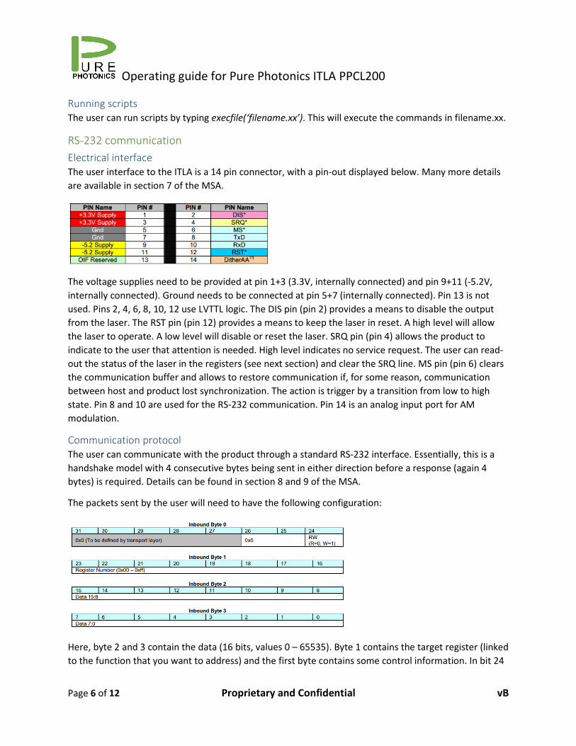
The user interface to the ITLA is a 14 pin connector, with a pin-out displayed below. Many more details
are available in section 7 of the MSA.
The voltage supplies need to be provided at pin 1+3 (3.3V, internally connected) and pin 9+11 (-5.2V,
internally connected). Ground needs to be connected at pin 5+7 (internally connected). Pin 13 is not
used. Pins 2, 4, 6, 8, 10, 12 use LVTTL logic. The DIS pin (pin 2) provides a means to disable the output
from the laser. The RST pin (pin 12) provides a means to keep the laser in reset. A high level will allow
the laser to operate. A low level will disable or reset the laser. SRQ pin (pin 4) allows the product to
indicate to the user that attention is needed. High level indicates no service request. The user can read-
out the status of the laser in the registers (see next section) and clear the SRQ line. MS pin (pin 6) clears
the communication buffer and allows to restore communication if, for some reason, communication
between host and product lost synchronization. The action is trigger by a transition from low to high
state. Pin 8 and 10 are used for the RS-232 communication. Pin 14 is an analog input port for AM
modulation.
Communication protocol
The user can communicate with the product through a standard RS-232 interface. Essentially, this is a
handshake model with 4 consecutive bytes being sent in either direction before a response (again 4
bytes) is required. Details can be found in section 8 and 9 of the MSA.
The packets sent by the user will need to have the following configuration:
Here, byte 2 and 3 contain the data (16 bits, values 0 – 65535). Byte 1 contains the target register (linked
to the function that you want to address) and the first byte contains some control information. In bit 24
Operating guide for Pure Photonics ITLA PPCL200
Page 7 of 12 Proprietary and Confidential vB
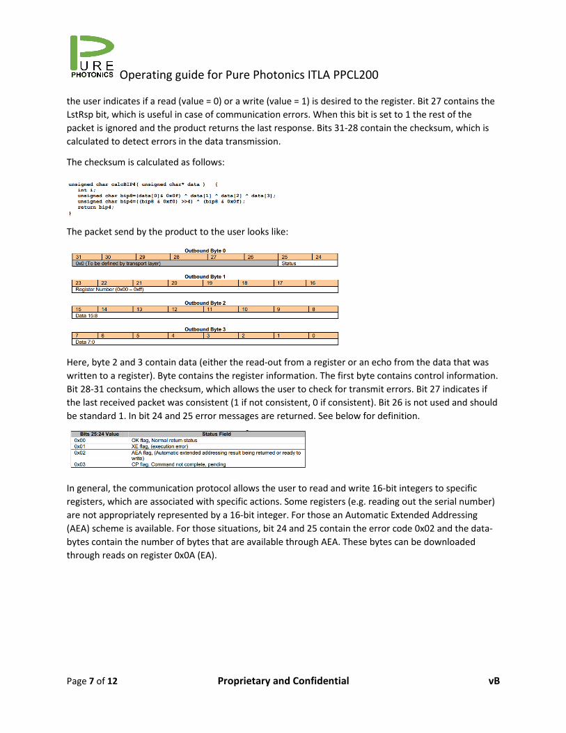
the user indicates if a read (value = 0) or a write (value = 1) is desired to the register. Bit 27 contains the
LstRsp bit, which is useful in case of communication errors. When this bit is set to 1 the rest of the
packet is ignored and the product returns the last response. Bits 31-28 contain the checksum, which is
calculated to detect errors in the data transmission.
The checksum is calculated as follows:
The packet send by the product to the user looks like:
Here, byte 2 and 3 contain data (either the read-out from a register or an echo from the data that was
written to a register). Byte contains the register information. The first byte contains control information.
Bit 28-31 contains the checksum, which allows the user to check for transmit errors. Bit 27 indicates if
the last received packet was consistent (1 if not consistent, 0 if consistent). Bit 26 is not used and should
be standard 1. In bit 24 and 25 error messages are returned. See below for definition.
In general, the communication protocol allows the user to read and write 16-bit integers to specific
registers, which are associated with specific actions. Some registers (e.g. reading out the serial number)
are not appropriately represented by a 16-bit integer. For those an Automatic Extended Addressing
(AEA) scheme is available. For those situations, bit 24 and 25 contain the error code 0x02 and the data-
bytes contain the number of bytes that are available through AEA. These bytes can be downloaded
through reads on register 0x0A (EA).
Operating guide for Pure Photonics ITLA PPCL200
Page 8 of 12 Proprietary and Confidential vB
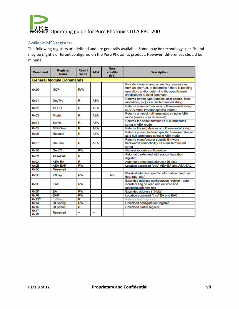
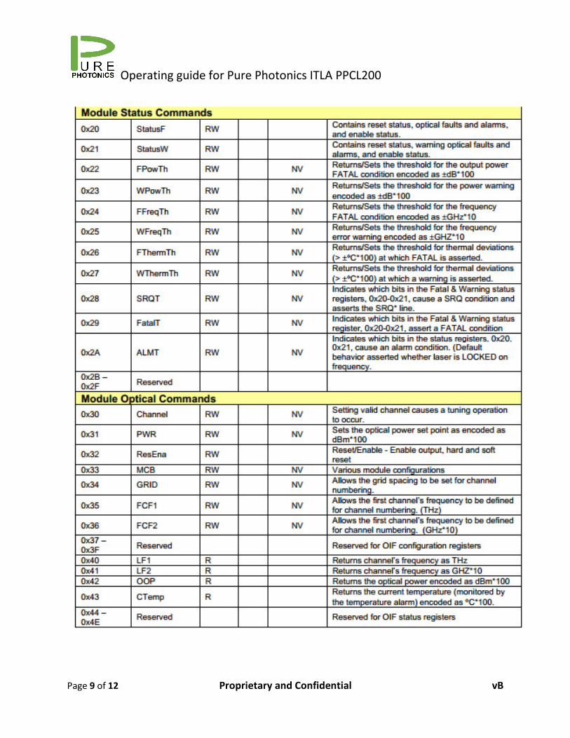
Available MSA registers
The following registers are defined and are generally available. Some may be technology specific and
may be slightly different configured on the Pure Photonics product. However, differences should be
minimal.
Operating guide for Pure Photonics ITLA PPCL200
Page 9 of 12 Proprietary and Confidential vB
Operating guide for Pure Photonics ITLA PPCL200
Page 10 of 12 Proprietary and Confidential vB
Operating guide for Pure Photonics ITLA PPCL200
Page 11 of 12 Proprietary and Confidential vB
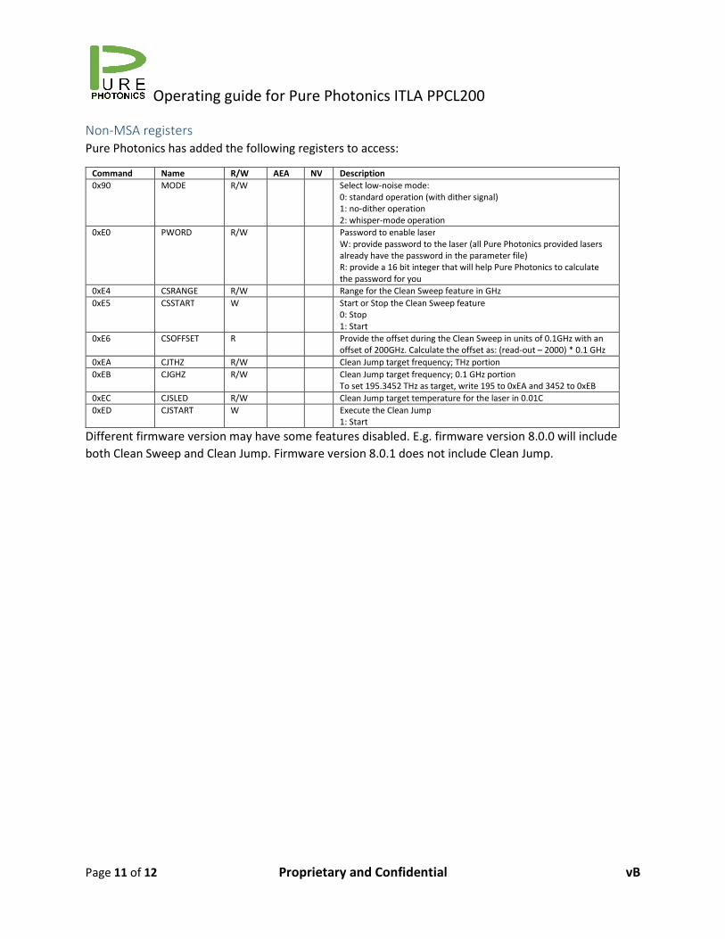
Non-MSA registers
Pure Photonics has added the following registers to access:
Command Name R/W AEA NV Description
0x90 MODE R/W Select low-noise mode:
0: standard operation (with dither signal)
1: no-dither operation
2: whisper-mode operation
0xE0 PWORD R/W Password to enable laser
W: provide password to the laser (all Pure Photonics provided lasers
already have the password in the parameter file)
R: provide a 16 bit integer that will help Pure Photonics to calculate
the password for you
0xE4 CSRANGE R/W Range for the Clean Sweep feature in GHz
0xE5 CSSTART W Start or Stop the Clean Sweep feature
0: Stop
1: Start
0xE6 CSOFFSET R Provide the offset during the Clean Sweep in units of 0.1GHz with an
offset of 200GHz. Calculate the offset as: (read-out – 2000) * 0.1 GHz