Operating Instruction D184B069U02 Electromagnetic Flowmeter FXP4000 (PARTI-MAG II) for Full and Partially Full Pipelines (Free and Surface Pipeline) Valid as of software-level A.20 Flowmeter Primary: FXP4000-DP41F FXP4000-DP46F External Converter: FXP4000-XP2 (50XP2000)
Transcript
Operating InstructionD184B069U02
Valid as of software-leve
Flowmeter Primary:FXP4000-FXP4000-
External Converter:FXP4000-
Electromagnetic FlowmeterFXP4000 (PARTI-MAG II)
for Full and Partially Full Pipelines(Free and Surface Pipeline)
This document is protected by copyright. Information in this document ist intended only to assist the userin safe and efficient operation of the equipment. Its content are not to be reproduced in full or part withoutprior approval of legal owner.
2
Introductory Safety Notes for the EMF System
Regulated Usage The electromagnetic flowmeter system PARTI-MAG II is designed to the latest state of the art technology and is safe to operate. The PARTI-MAG II is to be installed only in the specified applications.
Every usage which exceeds the specified applications is considered to be non-speci-fied. Any damages resulting therefrom are not the responsibility of the manufacturer.
The application specifications include the installation, start up, and service require-ments specified by the manufacturer.
Installation, Start Up, and Service Personnel Please read this Instruction Manual and the safety notes before attempting installa-tion, start up, or service.
Only qualified personnel should have access to the instrument. The personnel should be familiar with the warnings and operating requirements contained in this Instruction Manual.
Observe that the connections are in accordance with the interconnection diagrams. Ground the flowmeter system.
Observe the warning notes designated in this document by the symbol:
Hazardous Material Information In view of the Disposal Law of 27.08.86 (AbfG. 11 Special Wastes) the owner of special wastes is responsible for its care and the employer also has, according to the Hazard-ous Material Law of 01.10.86 (GefStoffV, 17 General Protection Responsibility), a re-sponsibility to protect his employees, we must make note that:
a) All flowmeter primaries and/or converters which are returned to ABB Automation Products for repair are to be free of any hazardous materials (acids, bases, solu-tions, etc.)
b) The flowmeter primaries must be flushed so that the hazardous materials are neu-tralized. There are cavities in the primaries between the metering spool and the housing. Therefore after metering hazardous materials the cavities are to be neu-tralized (see Hazardous Material Law -GefStoffV). For two piece housings the screws used to hold the sections together should be loosened. For primaries DN 350 the drain plug at the lowest point in the housing is to be opened to remove the hazardous materials and to neutralize the coil and electrode cavities.
c) For service and repair written confirmation is required that the measures listed in a) and b) have been carried out.
d) Any costs incurred to remove the hazardous materials during a repair will be billedto the owner of the equipment.
1 Functional Description The electromagnetic flowmeters from ABB Automation Prod-ucts “EMF” are the ideally suited flowmeters for metering the flow of all liquids, slurries and sludges who have a specific min-imum electrical conductivity. These flowmeters measure accu-rately, create no additional pressure drop, contain no moving or protruding parts, are wear free and corrosion resistant. Installations are possible in all existing piping systems without difficulty.
The ABB Automation Products “EMF” has proven itself over many years and is the preferred flowmeter in the chemical in-dustry, the municipal water and waste water treatment facilities, the food and paper industries.
1.1 Measurement Principle of PARTI-MAG IIThe Faraday’s Laws of Induction form the basis for the electro-magnetic flowmeter. The conductive fluid flows through the metering tube perpendicular to the direction of the magnetic field
UE ~ B · D ·V
The voltage induced in the fluid is measured by a number of electrode pairs. These are located in the metering tube so that at every flow cross section (full or partially full) the appropriate weighting factor corrected electrode pair is utilized for the flow signal measurement. An additional electrode is integrated for full pipe recognition.
The four electrode pairs in addition to optimally measuring the average flow velocity detect a superimposed alternating current field for determination of the fill height.
Utilizing the characteristic curves stored in the converter and the fill height information the signal voltage UE is corrected and converted to a flowrate proportional output signal.
1.2 DesignThe eletromagnetic flowmeter PARTI-MAG II consists of a flow-meter primary model DP41F (standard) or model DP46F (Ex-design) which is installed in the pipeline an of a converter model FXP4000-XP2 (50XP2000) which can be mounted locally or at a central station remote. The max. allowable length of the signal cable between flowmeter primary and remotely mounted converter is 50 m. The converter has to be mounted outside the ex-area.
UE = Signal VoltageB = Magnetic InductionD = Electrode Spacingv = Average Flow Velocityqv = Volume Flowrate
UE B . D . v
UE qv
∼
qvD2π
4----------
··v⋅=
∼
Fig. 1 Measurement Principle
6
Flowmeter Primary Model DP41F/DP46F
2 Safety2.1 General Safety InformationThe "Safety" chapter provides an overview of the safety as-pects to be observed for the operation of the device.
The device is built based on state-of-the-art technology and is operationally safe. It was tested and left the factory in a proper state. The requirements in the manual as well as the documen-tation and certificates must be observed and followed in order to maintain this state for the period of operation.
The general safety requirements must be complied with com-pletely during operation of the device. In addition to the general information, the individual chapters of the manual contain de-scriptions about processes or procedural instructions with spe-cific safety information.
Only the observance of all safety information enables the opti-mal protection of personnel as well as the environment from hazards and the safe and trouble-free operation of the device.
2.2 Intended useThis device is intended for the following uses:
• To transmit fluid or pulpy substances with electrical conductivity.
• To measure the flowrate of the operating volume.
The following items are included in the intended use:
• Read and follow the instructions in this manual.• Observe the technical ratings; refer to the section
"Technical limit values".• Use only allowed liquids for measurement; refer to the
section "Allowed fluids".
2.3 Improper useThe following uses of the device are prohibited:
• Operation as a flexible adapter in piping, e.g., to compen-sate for pipe offsets, pipe vibrations, pipe expansions, etc.
• Use as a climbing aid, e.g., for assembly purposes.• Use as a support for external loads, e.g., as a support for
pipes, etc.• Material gain, e.g., by painting over the name plate or add-
ing parts by welding / soldering.• Material loss, e.g., by drilling the housing.
Repairs, alterations and enhancements or the installation of re-placement parts is only permissible as far as described in the manual. Further actions must be verified with ABB Automation Products GmbH. Excluded from this are repairs performed by ABB-authorized specialist shops.
2.4 Technical limit valuesThe device is designed for use exclusively within the stated val-ues on the name plate and within the technical limit values specified in the data sheets.
The following technical limit values must be observed:
• The permissible pressure (PS) in the permissible fluid tem-perature (TS) may not exceed the pressure-temperature ratings.
• The maximum operating temperature may not be exceeded.
• The permitted ambient temperature may not be exceeded.• The housing protection class must be observed.• The flowmeter primary may not be operated in the vicinity of
powerful electromagnetic fields, e.g., motors, pumps, trans-formers, etc. A minimum spacing of approx. 100 cm should be maintained. For installation on or to steel parts (e.g., steel brackets), a minimum spacing of approx. 100 mm should be maintained (based on IEC801-2 and IECTC77B).
2.5 Allowed FluidsWhen measuring fluids, the following points must be observed:
• Fluids may only be used if, based on state-of-the-art tech-nology or the operating experience of the user, it is assured that chemical and physical properties of the components coming into contact with the fluids (signal electrodes, ground electrodes, liners and, possibly, process connec-tions, protective plates or protective flanges) are not affect-ed during the operating life.
• Fluids with unknown properties or abrasive agents may only be used if the operator can perform regular and suitable tests to ensure the safe condition of the device.
• Observe the information on the name plate.
2.6 Operator liability Before the use of corrosive and abrasive measuring medium, the operator must clarify the resistance of all parts that come into contact with the medium to be measured. ABB will gladly support you with the selection, however, cannot accept any liability.
The operators must strictly observe the applicable national reg-ulations in their countries with regards to installation, function tests, repairs, and maintenance of electrical devices.
2.7 Personnel qualification The installation, commissioning and maintenance of the device may only be carried out through trained specialist personell authorized by the plant operator. The specialist personnel must have read and understood the manual and comply with its instructions.
7
Flowmeter Primary Model DP41F/DP46F
2.8 Installation safety informationObserve the following instructions:
• The flow direction must correspond to the direction indicat-ed on the device, if labeled.
• Comply with the maximum torque for all flange bolts.• Install the devices without mechanical tension (torsion,
bending). • Install flange units with coplanar counter flanges.• Only install devices for the intended operating conditions
and with suitable seals.• Secure the flange bolts and nuts against pipeline vibrations.
2.9 Electrical installation safety informationThe electrical connection may only be performed by authorized specialists according to the electrical plans.
Comply with electrical connection information in the manual. Otherwise, the electrical protection can be affected.
Ground the measurement system according to requirements.
2.10 Operating safety informationDuring operation with hot fluids, contact with the surface may result in burns.
Aggressive fluids may result in corrosion and abrasion of the liner or electrodes. As a result, pressurized fluids may escape prematurely.
Due to wear on the flange seal a pressurized medium may escape.
2.11 Maintenance and inspection safety information
Warning - Risk to persons!When the housing cover is open, EMC and protection against contact are suspended. There are electric cir-cuits within the housing which pose a contact risk.
The auxiliary power must be switched off before open-ing the housing cover.
Warning - Risk to persons!The inspection screw (for draining condensate fluid) for devices ≥ DN 300 can be under pressure. The medium which spurts out can cause severe injuries.
Depressurize pipes before opening the inspection screw.
Corrective maintenance work may only be performed by trained personnel.
• Depressurize the device and adjoining lines or containers before removing the device.
• Check whether hazardous materials are used as materials to be measured before opening the device. Residual amounts of hazardous material may still be present in the device and could escape when the device is opened.
• As far as provided in the scope of the operational responsi-bility, check the following items through a regular inspection:- the pressure-carrying walls / lining of the pressure device,- the measurement-related function,- the leak tightness,- the wear (corrosion).
8
Converter Model FXP4000-XP2 (50XP2000)
3 Transport3.1 InspectionCheck the devices for possible damage that may have occurred from improper transport. Damages in transit must be recorded on the transport documents. All claims for damages must be claimed without delay against the shipper and before the instal-lation.
3.2 General information on transportObserve the following when transporting the device to the mea-surement site:
• The center of gravity may not be in the center of the device.• The protective pates or dust caps mounted at the process
connections of devices equipped with PTFE/PFA may only be removed before installation. To prevent possible leak-age, make sure that the liner is not cut or damaged.
• Flanged units may not be lifted by the terminal box.
3.3 Transport of flanged units
Warning - Danger of injuries due to slipping meter.The center of gravity for the complete device may be higher than the lifting straps.
Make sure the device has not rotated or slipped unintentionally during transport. Support the meter laterally.
For transport of flanged units < DN 300 use a lifting strap. Wrap the straps around both process connections when lifting the device. Avoid chains since these may damage the housing.
Fig. 2 Transport of flanged units < DN 300
Fig. 3 Transport of flanged units > DN 250
G00460
G00461
9
Converter Model FXP4000-XP2 (50XP2000)
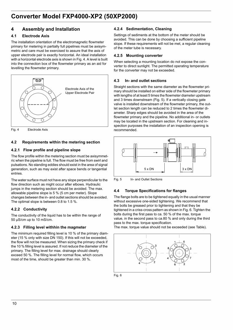
4 Assembly and Installation 4.1 Electrode AxisThe installation orientation of the electromagnetic flowmeter primary for metering in partially full pipelines must be axisym-metric and care must be exercised to assure that the axis of upper electrode pair is exactly horizontal. An ideal installation with a horizontal electrode axis is shown in Fig. 4. A level is built into the connection box of the flowmeter primary as an aid for levelling the flowmeter primary.
4.2 Requirements within the metering section
4.2.1 Flow profile and pipeline slopeThe flow profile within the metering section must be axisymmet-ric when the pipeline is full. The flow must be free from swirl and pulsations. No standing eddies should exist in the area of signal generation, such as may exist after space bends or tangential entries.
The water surface must not have any slope perpendicular to the flow direction such as might occur after elbows. Hydraulic jumps in the metering section should be avoided. The max. allowable pipeline slope is 5 % (5 cm per meter). Slope changes between the in- and outlet sections should be avoided. The optimal slope is between 0.8 to 1.5 %.
4.2.2 ConductivityThe conductivity of the liquid has to be within the range of 50 µS/cm up to 10 mS/cm.
4.2.3 Filling level withhin the magmeterThe minimum required filling level is 10 % of the primary diam-eter (15 % only with size DN 150). If this will not be exceeded, the flow will not be measured. When sizing the primary check if the 10 % filling level is assured. If not reduce the diameter of the primary. The filling level for max. drainage should clearly exceed 50 %. The filling level for normal flow, which occurs most of the time, should be greater than min. 30 %.
4.2.4 Sedimentation, CleaningSettings of sediments at the bottom of the meter should be avoided. This can be done by choosing a sufficient pipeline slope. If these requirements will not be met, a regular cleaning of the meter tube is necessary.
4.2.5 Mounting converterWhen selecting a mounting location do not expose the con-verter to direct sunlight. The permitted operating temperature for the converter may not be exceeded.
4.3 In- and outlet sectionsStraight sections with the same diameter as the flowmeter pri-mary should be installed on either side of the flowmeter primary with lengths of at least 5 times the flowmeter diameter upstream and 3 times downstream (Fig. 5). If a vertically closing gate valve is installed downstream of the flowmeter primary, the out-let section length can be reduced to 2 times the flowmeter di-ameter. Sharp edges should be avoided in the area of the flowmeter primary and the pipeline. No additional in- or outlets may be located in the upstream section. For cleaning and in-spection purposes the installation of an inspection opening is recommended.
4.4 Torque Specifications for flangesThe flange bolts are to be tightened equally in the usual manner without excessive one-sided tightening. We recommend that the bolts be greased prior to tightening and that they be tightened in a criss-cross pattern as shown in Fig. 6. Tighten the bolts during the first pass to ca. 50 % of the max. torque value, in the second pass to ca.80 % and only during the third pass to the max. torque specification.The max. torque value should not be exceeded (see Table).
Electrode Axis of the Upper Electrode Pair
Fig. 4 Electrode Axis
5 x DN 3 x DN
Fig. 5 In- and Outlet Sections
Fig. 6
10
Converter Model FXP4000-XP2 (50XP2000)
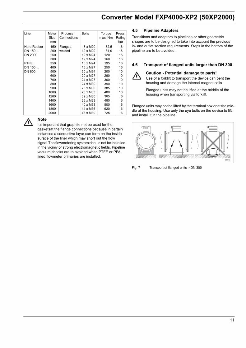
NoteItis important that graphite not be used for the gasketsat the flange connections because in certain instances a conductive layer can form on the inside surace of the liner which may short out the flow signal.The flowmetering system should not be installed in the viciniy of strong electromagnetic fields. Pipeline vacuum shocks are to avoided when PTFE or PFA lined flowmeter primaries are installed.
4.5 Pipeline AdaptersTransitions and adaptors to pipelines or other geometric shapes are to be designed to take into account the previous in- and outlet section requirements. Steps in the bottom of the pipeline are to be avoided.
4.6 Transport of flanged units larger than DN 300
Caution - Potential damage to parts!Use of a forklift to transport the device can bent the housing and damage the internal magnet coils.
Flanged units may not be lifted at the middle of the housing when transporting via forklift.
Flanged units may not be lifted by the terminal box or at the mid-dle of the housing. Use only the eye bolts on the device to lift and install it in the pipeline.
Fig. 7 Transport of flanged units > DN 300
Liner MeterSizemm
Process Connections
Bolts Torquemax. Nm
Press.Rating
barHard RubberDN 150 ...DN 2000
PTFE:DN 150 ...DN 600
150200250300350400500600700800900
100012001400160018002000
Flanged,welded
8 x M2012 x M2012 x M2412 x M2416 x M2416 x M2720 x M2420 x M2724 x M2724 x M3028 x M3028 x M3332 x M3036 x M3340 x M3344 x M3648 x M39
82,581,0
120160195250200260300390385480365480500620725
161616161616101010101010
66666
G00462
11
Converter Model FXP4000-XP2 (50XP2000)
5 Programming of the converter5.1 GeneralThe present flow direction is displayed in the first line (>F for Forward < R for Reverse) together with the instantaneous flowrate value in percent or engineering units. Optionally the fill height (Fh) in percent can also be displayed.
The totalizer value for the present flow direction is displayed in the second line with a maximum of 7 digits followed by the corresponding units. The totalizer value represents the actually measured flow volume independent of the pulse factor settings. This display configuration is designated as “Process Informa-tion” in the following text.
The totalizer value for the other flow direction can be displayed by pressing the Tot.-key.
A totalizer overflow occurs whenever the totalizer value reaches 9,999,999 units. When the totalizer value for one of the flow directions exceeds 9,999,999 units, the flow direction indicator in the second line blinks (>F or <R) together with the totalizer units (e.g. m3). The software can record up to 255 totalizer overflows. The overflow message can be cleared for each flow direction by pressing ENTER.
The totalizer has overflowed; >F and m3 blink.
If an error is detected an error message is displayed in the first line. For information, please refer to chapter 5.1.
When the fill height drops below 10% of the flowmeter primary diameter the output signals are automatically turned off and a corresponding error message is displayed on the converter. The output signals are turned off when the fill height is less than 15 % in meter size 150 only.
In addition to the error message in the display (applies to all error messages) the alarm relay is actuated. The current output can be configured to go to either 0 or 130 % when the alarm relay has been activated. In addition all error messages are stored in the Submenu "Instrument Status" and differing from the process information display, all error messages are described in detail.
→ F 98.14 %→ F 12.0000 m3
→ F 78.97 %→ F 23455.1 m3
Error 3→ F 120.0 m3
Flowrate > 130 %→ F 120.0 m3
Partially< 10 % of Diameter
12
Converter Model FXP4000-XP2 (50XP2000)
5.2 Data Entry at the ConverterData is entered using the 16-key foil keypad. The desired parameter or function can be selected using the Direct Access keys (meter size, meter range, Qmax, pulse factor, damping and low flow cutoff) or by scrolling with the arrow keys.
The name of the parameter is displayed in the first line its setting value with units in the second line. An automatic return to the process information display occurs after ca. 20 seconds or immediately by pressing the C/CE-key.
The converter always remains on-line during the configuration, i.e. the current and pulse outputs continue to indicate the present operating status. Other control devices connected to the output do not have to be switched “manual” when accessing or changing operating parameters. No internal totalizer data is lost.
The Language information are displayed with is english. There is no possibility to switch over to another language.
Parameter selectionArrow key, scroll up
Parameter selectionArrow key, scroll down
Double function key1. Direct access key Meter size2. Number 1 (for numeric entry)
Double function key1. Direct access key Meter range2. Number 2 (for numeric entry)
Double function key1. Flow range setting Qmax2. Number 3 (for numeric entry)
Double function key1. Direct access key Display2. Number 4 (for numeric entry)
Double function keyLow flow cutoff2. Number 5 (for numeric entry)
Double function key1. Direct access key Pulse factor2. Number 6 (for numeric entry)
Double function key1. Direct access key Submenu Totalizer2. Number 7 (for numeric entry
Double function key1. Direct access key Submenu Self test2. Number 8 (for numeric entry)
Double function key1. Direct access key Damping2. Number 9 (for numeric entry
Double function key1. Direct access key “Load data from ext.
EEPROM” (when exchanging converter, upload all meter location parameters into new converter)
2. Number 0 (for numeric entry
Double function key1. Direct access key “Store data in ext.
EEPROM (store all meter location parameters at start-up)
2. Comma
Press ENTER to access the parameter to be changed and accept the new parameter
Return to the process display;Erase incorrectly entered data
Double function key1. Key for sign - (minus) for numeric data entry2. Display of the totalizer value for the other
flow direction
Adjust display contrast with a small screwdriver to local ambient conditions.
Control Processing UnitThe diode blinks if the CPU (processor) has failed.In this case contact the ABB Automation Products Service Department
13
Converter Model FXP4000-XP2 (50XP2000)
Settings can only be changed at the converter when the program protection has been turned off.
If the operator attempts to change data in the converter when the program protection is turned on the following message is displayed:
If the program protection is turned off parameters can be changed.
There are two methods to turn the program protection off
a) The program protection code (PP-code) is set to 0.(Factory setting)
b) Another protection code is set (1-255)
It is possible to change the PP-Code after the program protection has been turned off:
There two entry modes for entering data:
a) direct numerical entry andb) selection from a table
5.2.1 Direct Numeric EntryThe following procedure is used for entering numeric values directly:
1. Access the desired parameter either with the Direct Access key or by using one of the arrow keys. The parameter is displayed in the first line
The value together with its units is displayed in the second line
To Change Use Keypad = Display-Information
Starting point“Process Information”
⎯ F 98.14 %F 13.422 m3
Parameter“Prog. protection”find using one of the arrow keys
Prog. protectionon
“Program protection”turn off
Prog. protectionoff
To Change Use Keypad = Display-Information
Starting point“Process information”
⎯ F 98.14 %F 13.422 m3
Parameter“Prog. protection”find with one of thearrow keys
Prog. protectionon
PP-Codeenter
PP-Code-
“Program protection”turn off
Prog. protectionoff
* Error ** Protection Code *
To Change Use Keypad = Display-Information
Starting point“Prog. protection OFF”
⎯ Prog. protectionoff
Parameter“Prog. protection” code
PP-Code
Old PP-Code enter(Factory setting. = 0
Old PP-Code
Enter new PP-Code turn off
Prog. protectionoff
The new PP-Codeis now valid ⎯
PP-Code
To Change Use Keypad = Display-Information
Parameterset “Qmax” ”
⎯ Qmax1800.00 m3/h
Parameter“Prog. protection”find with one of the arrow keys
Qmax0 m3/h
“Program protection”turn off
Prog. protectionoff
14
Converter Model FXP4000-XP2 (50XP2000)
2. Press the ENTER-key. The text in the second line is cleared while the first line remains unchanged. A numeric entry now can be made.
3. Data entry starts with the most significant figure. After the entire value has been entered the new value can be accepted by pressing the ENTER-key. The new value is stored in the computer and displayed.
5.2.2 Entry from a Table
5.3 Terminate Data Entry and Exit Programming Mode
The entry is cleared by pressing the C/CE-key. Pressing C/CE a second time displays the value of the old setting and pressing the C/CE-key once more returns to the display of the process information.
To Change Use Keypad = Display-Information
Parameter“Qmax” set
Qmax6 2 4 0 , 00 m3/h
After “Enter” a cursor is displayed. Enter the new value from the key-pad beginning with the most significant figure
Accept new Qmax value
Qmax6 2 4 0 , 00 m3/h
To Change Use Keypad = Display-Information
Parameter”Unit totalizer” set
Unit totalizerm3
Parameter“Unit totalizer” change
Unit totalizerm3
Find desired unit in the table using the arrow keys
Unit totalizerl
Accept new unit Unit totalizerl
To Change Use Keypad = Display-Information
Exit Qmax or unit total-izer. Parameter find “Program protection” with one of the arrow keysAccept new Qmax value
Turn Program protec-tion on again
Starting point Process information (converter remains on-line)
Prog. protectionoff
Prog. protectionoff
F 98.14 %F 18.324 m3
6240,00
15
Converter Model FXP4000-XP2 (50XP2000)
6 Parameter Overview with Display in Table Format
Key Parameter Entry Mode Commentstabular On / Off
Exit from Submenu
Old PP-Code (Program protection code) enter.Factory setting is “0”
Enter new PP-CodeEntry range 0-255
The parameters in the Submenu are read only.
Present meter sizesee flowmeter primary instrument Tag
Automatic selection of the max. flowrate for the selectedmeter size. Flow range end value can be setfrom 0,05 QmaxDN -QmaxDN
Flowmeter primary short model number
Flowmeter order number. This number is listed on theflowmeter primary instrument tag.
tabular For int. and ext. flow totalization, range 0.001 - 1000 pulsesper selected unit, max. count frequency 5 kHz
numeric For external pulse output, range 0,1 ms - 2000 ms
numeric Range 10 - 200 sResponse time for 0-99 % flowrate change
numeric Range 0 - 10 % for the indication in the display and alloutputs
tabular/numeric Exit from Submenu
The contact outputs (P1-P2, P3-P4) can be configured bythe software:a) no functionb) F/R-Signal (forward/reverse direction signal)c) MAX-Alarm flowrate Q↑d) MIN-Alarm flowrate Q↓e) Fill height < 0,1 x meter sizef) MAX-Alarm fill height (F↑)g) MIN-Alarm fill height (F↓)
Settings of MIN-Alarm 0-130 %.The alarm is indicated in the display by ↓ The contact inputs(22-U2, 31-U2) can be configured in thesoftwarea) no functionb) external zero return
External zero return. Alarm in activated(Error 4) and the current output is set to its error mode value.The pulse output is set to 0.
c) Ext. totalizer resetAll totalizer and totalizer overflows are reset. A correspondingmessage is displayed.
In addition to the message in the display the alarm relay isactuated. With this submenu a setting can be made whetherthe relay should be actuated or not. (ON/OFF) when fillheight is below 10 % of meter size.
Exit from Submenu
Range 0-20 mA/4-20 mA, 0-10 mA/2-10 mA
0-10, 10-20 mA/4-12, 12-20 mA 0/4-20 mA
During an error condition the current output is set to the value selected here.Selections are: 0 %, 130 % or 3,6 mA
see Iout at Alarm
6Puls Pulse factor
10.000 /m3
Pulse width30.000 ms
9Damp. Damping
10.000 s
Low flow cutoff1.0000 %
SubmenuProg. In/Output
C/CE
ENTER
Output P1-P2MIN-Alarm
Output P3-P4MAX-Alarm
Input 22-U2no function
Input 31-U2no function
Alarm fill height < 0,1off
SubmenuCurrent output
C/CE
ENTERCurrent output0 - 20 mA
Iout at Alarn130 %
Iout at e. pipe130 %
17
Converter Model FXP4000-XP2 (50XP2000)
18
Key Parameter Entry Mode Comments
A selection can be made if the flowrate or the fill height (Fh)should be indicated by the current output.
tabular/numericThe Submenu Data Link is only displayed when a RS 232/RS 485 has been installed.
Communication protocol ASCII.This protocol is described in a separate document.
Instrument address:0-99
Baudrate: 1200-9600 Baud
Exit from Submenu
! The flow measurements are interrupted when theSubmenu “Self test” is selected.
Self test of current output range can be set 0-26 mASelf test internal elements, automatically test. RAM,EPROM, EEPROM, external EEPROM. Additional functions:Alarm contact, P1-P2-contact, P3-P4-contact, Fout(frequency output) input 22-U2, input 31-U2, Test Mode (for operation with a simulator).
Exit from Submenu
OFF = Detector without functionON = When pipe is full, flowrate will be calculated
similar to common magmeter flowrate calculation.
Set threshold to 2400 Hz (factory setting). The threshold value should be about 400 Hz greater than it´s adjustmentvalue when measured with a full pipe.
The pipe line must be full pressing ENTER button thefollowing display occurs:
Using the arrow keys adjust the reading to 2000 ± 25 Hz.Accept adjustment value with ENTER.
Exit from Submenu
Process display: Various values can be selected for the process information display (independently for each displayline). e.g. Q [%], inst. flowrate in percent, Q [eng´g units] inst.flowrate in mA [current output], F/R: totalizer value for theforward- and reverse totalizers, TAG-number, Fill heightin %. See 1. line
Iout selectFlowrate Q [mA]
SubmenuData Link ENTER
CommunicationASCII
Address004
Baudrate2400 Baud
8Test Submenu
Self test ENTERC/CE
Self testCurrent output
Self testRAM (ASIC)
SubmenuDetector full pipe ENTER
C/CE
Detector full pipeoff
Threshold2400 Hz
AdjustDetector full pipe
Poti: 1932000 Hz
4Display Submenu
Display ENTERC/CE
1. LineQ [%]
2. LineTotalizer
Converter Model FXP4000-XP2 (50XP2000)
19
Key Parameter Entry Mode Comments
An additional value can be selected for display in the 1st linein the multiplex mode: flowrate in % or eng´g units, mA,totalizer, totalizer forward, totalizer reverse, TAG-number,or off. switches every 10 sec., see 1. line multipl.
tabular/numericExit from Submenu
Active error messages (description see chapter 5) aredisplayed. Instrument status A: Error messages for uppercoil (A) ir ASIC (A).
Instrument status B: Error messages for lower coil (B) orASIC (B).
Instrument status C: Error messages during systemmonitoring or internal instrument error.
Instrument status D
Instrument status E
Instrument status F
All errors detected are stored.Reset by pressing ENTER.
All errors detected are stored.Reset by pressing ENTER.
All errors detected are stored.Reset by pressing ENTER.
All errors detected are stored.Reset by pressing ENTER.
All errors detected are stored.Reset by pressing ENTER.
All errors detected are stored.Reset by pressing ENTER.
Alarm limit for the flowrate, entry range 0 - 130 %of the flow range setting.
Alarm limit for the flowrate, entry range 0 - 130 %of the flow range setting.
Alarm limit for fill height, entry range 0 to 100 %.
1. Line multipl.TAG Number
2. Line multipl.off
SubmenuAlarm ENTER
C/CE
Status A2pA. 2nA. 7A. 8A
Status B2pB. 2nB. 7B. 8B
Status C0.4.5.6v6r9.E.H
Status D0.3.A.B.F.G
Status ECc. Cd. Dc. Dd.
Status F1pA. 1nA. 1pB. 1nB
Status reprot A2pA. 2nA. 7A. 8A
Status report B2pB. 2nB. 7B. 8B
Status report C0.4.5.6.9....
Status report D0.3.A.B.F.G
Status report ECc. Cd. Dc. Dd.
Status report F1pA. 1nA. 1pB. 1nB
Max. Alarm Q↑95 %
Min. Alarm W↓9 %
Max. Alarm Fh↑10 %
Converter Model FXP4000-XP2 (50XP2000)
Key Parameter Entry Mode Comments
Alarm limit for fill heightEntry range 0 to 100 %
tabularExit from Submenu
The forward totalizer is reset by pressing ENTER
Pressed totalizer (forward direction)
Overflow counter max. 250, 1 Overflow = totalizer pulses>9.999.999 units (display indication is reset and overflowcounter incremented by 1). The overflow counter can bereset by pressing ENTER.
See forward totalizer
Pressed totalizer (forward direction)
See overflow counter
Exit from Submenu
Flow direction selectionForward/reverse of forward only
Normal/InverseReverse the flow direction designations in the display.
tabular When replacing a converter all meter location parameterscan be uploaded into the new converter.
tabular After start-up all the parameters for the meter location mustbe stored on the external EEPROM on the terminal board.
Designation of the installed software version.10/97 = Release dateA.12 = Revision level
An alphanumeric TAG-number with a maximum of 16characters can be entered to define the meter location usingupper/lower case letters or numbers.
numeric Only for ABB Automation ProductsService.
Min. Alarm Fh ↓10 %
7Counter Submenu
Totalizer ENTERC/CE
Totalizer →Freset
Totalizer →F250.0 m3
Overflow →F>250
Totalizer ←Rreset
Totalizer →F250.0 m3
Overflow ←R004
SubmenuOperating mode ENTER
C/CE
Flow directionFwd/reverse
Flow direction displaynormal
0Load data fromext. EEPROM
,Store data inext. EEPROM
50XP2000 08/06D699B163U01 A35
TAG-Number
ABB Service Code
20
Converter Model FXP4000-XP2 (50XP2000)
7 Error Messages/Status Messages of the converter
7.1 Error Messages on the displayError messages are displayed alternately in clear text and with the corresponding error number. During the clear text display only the error with the highest priority is displayed, while other display indicates all the errors detected using their correspond-ing error number.
7.2 Error Messages of the Submenus “alarm”
7.2.1 “Status A” and “Status Report A”This display provides information about the alarm messages which affect the upper coil (A) or ASIC A. In the “Status A” display the present error messages are indicated. The “Status Report A” display indicates messages for all detected errors
Fill high is less than 10 % of the flowmeter primary diameterA/D converter saturatedReference votage too smallFlowrate greater than 130 %External zero return is activeData paramter EEPROM corruptedCorrupted totalizer valuesPositive reference voltage too largeNegative reference voltage too largeSupply power ferquency outside of the allowable limits
ErrorCode
System ErrorsDetected
Corrective Measures
1A ASIC A input saturated
Internal error, please contact ABB Service
2pA Positive reference voltage coil A too small
Check wiring andmagnetic field excitation
2nA Negative reference voltage coil A too small
7A Positive reference voltagecoil A too large
8A Negative reference voltage coil A too large
ErrorCode
System ErrorsDetected
Corrective Measures
1B ASIC B input saturated
Internal error, please contact ABB Service
2pB Positive reference voltage coil B too small
Check wiring andmagnetic field excitation
2nB Negative reference voltage coil B too small
7B Positive reference voltagecoil B too large
8B Negative reference voltage coil B too large
ErrorCode
System ErrorsDetected
Corrective Measures
4 Ext. zero return Zero return activated by pump or field contact
5 Data in parameter- EEPROM corrupted
Internal error, please contact ABB Service
6 Totalizer values corrupted Totalizer values are no longer valid, reset
9 Line frequency outside allowable tolerances
Check line frequency
H Power outage detected Reset error messageE Data in parameter
EEPROM corruptedReset error message
ErrorCode
System Errorsdetected
CorrectiveMeasuree
0 Fill height < 10 % of flow-meter primary diameter
A Max alarm limit value Decrease flowrateB Min alarm value Increase flowrateF Max alarm limit value Decrease fill levelG Min alarm limit value Increase fill level
ErrorCode
System Errorsdetected
CorrectiveMeasuree
Cc Injection of PSI-signalat electrode C too small
Contact ABB Service
Cd Injection of PSI-signalat electrode D too small
Contact ABB Service
Dc Injection of PSI-signalat electrode C too large
Contact ABB Service
Dd Injection of PSI-signalat electrode D to large
Contact ABB Service
21
Converter Model FXP4000-XP2 (50XP2000)
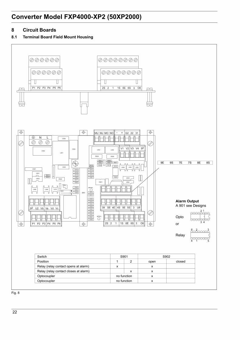
8 Circuit Boards8.1 Terminal Board Field Mount Housing
Switch S901 S902Position 1 2 open closedRelay (relay contact opens at alarm) x xRelay (relay contact closes at alarm) x xOptocoupler no function xOptocoupler no function x
Alarm OutputA 901 see Designs
Opto
or
Relay
9E 9S 7E 7S 8E 8S
Fig. 8
22
Converter Model FXP4000-XP2 (50XP2000)
8.2 Assembled Analog Board, supply voltage settings, pulse output settings, location of fuse
+
+
+
++
1
1X316
C105
N102
V120
V121
C104
C111
C102
V122
C103
L101
A13
A1
2A
11
1011
T101
1X1
1
1X13
Prim
„r
Sekund„r
1
46 2
R131
R132
6
Aufschlag
derL-S
eitebest ckt
Supply Voltage Settings
Pulse Output SettingsPulse active BR.9, 11, 13, 14 installed.Pulse opto only BR.10, 12 installed.
BR. 1 BR. 2 BR. 3 BR. 4 TransformerT 101
F 101 fuseABB part no.
230 V ac X D692B071U01 0,160 A T D151B025U02115 V ac X X D692B071U01 0,315 A T D151B025U0824 V ac X X D692B071U02 1,250 A T D151B025U04
Transformer Voltage Switches Fuse(see Table)
Data Link
Br.3 Br.2 Br.1
Br.14
13 12
9
Fig. 9
23
Converter Model FXP4000-XP2 (50XP2000)
8.3 Assembled Driver board
BR. 2 BR. 3 BR. 4 TransformerT 101
F 101 FuseABB Part Number
230 V ac X D692B072U01 0.160 A D151B025U02115 V ac X X D692B072U01 0.315 A D151B025U0824 V ac X X D692B072U02 1.250 A D151B025U04
TransformerVoltage Switches Fuse(see table)
Fig. 10
24
Flowmeter Primary
9 Specification flowmeter primary
9.1 Meter Size, Pressure Rating and Flow Ranges
NoteThe output signals are automatically turned off when the fill height drops below 10 % of the flowmeter primary diameter (with DN 150 min. fill-level must be 15 %).
9.2 Flowrate Nomograph for Full Pipes
MeterSize
mm
Standard Pressure
RatingPN
Min. Flow Range
Flow Velocity0 to 0.5 m/s
Max. Flow Range
QmaxDN0 to 10 m/s
150200250
10/1610/1610/16
0 to 8.33 l/s0 to 15.00 l/s0 to 25.00 l/s
0 to 166.7 l/s0 to 300,0 l/s0 to 500.0 l/s
300350400
10/1610/1610/16
0 to 33.33 l/s0 to 45.83 l/s0 to 62.50 l/s
0 to 667.0 l/s0 to 917.0 l/s0 to 1250 l/s
500600700
101010
0 to 91.67 l/s0 to 133.33 l/s0 to 183.33 l/s
0 to 1833 l/s0 to 2667 l/s0 to 3667 l/s
800900
1000
101010
0 to 272.20 l/s0 to 333.33 l/s0 to 375.00 l/s
0 to 5000 l/s0 to 6667 l/s0 to 7500 l/s
120014001600
666
0 to 590.00 l/s0 to 750.00 l/s0 to 1000.00 l/s
0 to 11600 l/s0 to 15000 l/s0 to 20000 l/s
18002000
66
0 to 1250.00 l/s0 to 1590.00 l/s
0 to 25000 l/s0 to 31700 l/s
Fig. 11 Flowmeter Primary
Flowrate
Volu
me
flow
rate
Fig. 12 Flow rate nomograph DN 150 - DN 2000
25
Flowmeter Primary
9.3 Model DP41F, DP46F9.3.1 General specificationsMin. allow. Pressure as a function of Fluid Temperature
Max. Allowable Ambient Temperature as a function of Fluid TemperatureFor flowmeters with carbon steel flangers
Fig. 13
For flowmeter with stainless steel flangers
Fig. 14Y = Ambient temperature °C/°FX = Fluid temperature °C/°F
Notes regarding min./max. measuring temperature
Materials, Flowmeter Primary
Process Connection Materials
Storage Temperature-20 ... 70 °C (-4 ... 158 °F)
Protection Class per EN 60529IP 67IP 68 (optional, max. Tauchtiefe: 5 m)
Pipeline Vibration Following EN 60068-2-6Converter• In the range of 10 - 55 Hz max. 0.15 mm deflection
Flowmeter primary• In the range of 10 - 55 Hz max. 0.15 mm deflection• In the range of 55 -150 Hz max. 2 g acceleration
DesignsThe flanged flowmeters comply with the installation lengths defined in VDI/VDE 2641, ISO 13359 or DVGW (W420, Design WP, ISO 4064 short).
Liner Meter Size POperationmbar abs.
at TOperation
Hard rubber 150 ... 250(6 ... 10“)
0 < 80 °C (176 °F)
300 ... 1000(12 ... 40“)
0 < 80 °C (176 °F)
Soft rubber 150 ... 250(6 ... 10“)
0 < 60 °C (140 °F)
300 ... 1000(12 ... 40“)
0 < 60 °C (140 °F)
PTFEKTW approved
150 ... 600(6 ...24“)
270400500
< 20 °C (68 °F)< 80 °C (176 °F)< 80 °C (176 °F)
Liner Flange material
Min. Temp. Max. Temp.
Hard rubber Steel -10 °C (14 °F) 80 °C (176 °F)stainless steel
1.4571-15 °C (5 °F) 80 °C (176 °F)
Soft rubber Steel -10 °C (14 °F) 60 °C (140 °F)stainless steel
1.4571-15 °C (5 °F) 60 °C (140 °F)
PTFE Steel -10 °C (14 °F) 80 °C (176 °F)stainless steel
1.4571-25 °C (-13 °F) 80 °C (176 °F)
60 [°C]140 [°F]
032
-10+14
80 [°C]176 [°F]
X
Y
-1014
60 [°C]140 [°F]
032
-25-13
80 [°C]176 [°F]
X
Y
-25-13
Parts Standard OptionsLiner PTFE, PFA, hard
rubber, soft rubber–
Signal and ground electrodes for– Hard rubber– Soft rubber
Explosion protectionSensor DP46FII 2 G EEx em [ib] IIC T4, EC-type Examination Certificate TÜV 97 ATEX 1219X
9.3.2 Ex-Data for model DP46FThe maximum allowable fluid temperatures [°C] are listed in the following table as a function of the maximum allowable ambient temperature and the flowmeter size:
The max. allowable fluid temperature (80 °C) is determined by the ther-mal fuse for the coils.
Allowable ambient temperature primary -20 ... 60 °C (-4 ... 140 °F)
9.3.3 Material load for flanged design model DP41F / DP46F
Limits for the allowable fluid temperature (TS) and allowable pressure (PS) are a function of the liner and flange materials of the flowmeter (see instrument name plate).
Temperature limits
DIN-Flange SS 1.4571 [316Ti] to DN 600 (24")
Fig. 15
ASME Flange SS1.4571[316TI] to DN 300 (12") (CL150/300) to DN 1000 (40") (CL150)
Supply PowerNominal voltage per Instrument Tag UN ± 1%
Straight Pipe Section Installation RequirementsUpstream > 10 x DN,Downstream > 5 x DN,DN = Flowmeter primary size
Warm Up Time30 min
AccuracyPartially Full(according to DIN 19559)
AccuracyFull Filling
accu
racy
% o
f rat
eac
cura
cy %
of r
ate
Fig. 21 Accuracy PARTI-MAG II
28
Flowmeter Primary
9.6 Dimensions Flowmeter Primary DN 150 to DN 250, DIN-flanges
Screw-Type Conduit Fittings PG 13.5
Screw-Type Conduit Fittings PG 21
All Dimensions in mm
Flange Dimensions Instrument Dimensions Weightca. kg
DN PN D d4 b A L L 1) L2) G E F H
150 1016
285285
212212
2525
170170
300300
305305
310310
275275
242242
148148
310310
2929
200 1016
340340
268268
2828
195195
350350
355355
360360
306306
274274
179179
340340
5656
250 1016
395405
320320
3030
250250
450450
455455
460460
334334
301301
207207
395405
8080
1) Standard with one grounding plate SS No.1.4571. Other materials and DN 300 and up upon request. See Note section 9.1 and Footnote Ordering Information Primary .For hard rubber liners + 2 mm for gasket.
2) With protection flange: Protection flanges provide the ground function, grounding plate not required.For hard rubber liners + 4 mm for gasket.
Fig. 22 Flowmeter Primary DN 150 to DN 250
29
Flowmeter Primary
9.7 Dimensions Flowmeter Primary DN 300 to DN 1000, DIN-flanges
1) > DN 1000 upon request2) Grounding plate DN 300 and up upon request. See Note “Grounding” section 9.1 and Footnote Ordering Information Flowmeter Primary 3) Protection flanges for PTFE-Liners provide the ground function, grounding plate not required
Flange DimensionsInstrument Dimensions
Weightca. kg
Protection Flange
without2) with 3)
DN1) PN D d4 b A L L G E F
300300
1016
445460
370378
3133
279279
500500
Upo
n re
ques
t
362362
329329
224224
112117
350350
1016
505520
430438
3135
322322
550550
387387
354354
249249
153162
400400
1016
565580
482490
3137
370370
600600
412412
380380
275275
166173
500500
1016
670715
585610
3339
407407
650650
448448
415415
311311
232277
600600
1016
780840
685725
3341
469469
780780
500500
466466
361361
283313
700700
1016
895910
800795
3541
537537
910910
543543
510510
405405
394408
800800
1016
10151025
905900
3743
605605
10401040
593593
560560
455455
441485
900900
1016
11151125
10051000
3945
671671
11701170
643643
610610
505505
757772
10001000
1016
12301255
11101115
3947
739739
13001300
693693
660660
555555
9601007
All Dimensions in mm
Screw-Type Conduit Fittings PG 13.5
Screw-Type Conduit Fittings PG 21
Fig. 23 Flowmeter Primary DN 150 to DN 250
30
Flowmeter Primary
9.8 Dimensions Flowmeter Primary DN 150 to DN 900, ASME-flanges
Meter Size Instrument Dimensions Flange Dimensions ASME CL 150
Weightapprox. kg.
DN Inch A L1) 2) E F G D d4 bISO
13359Old inst.length
150 6 170 300 450 242 139 275 279 216 29 39200250
810
195250
350450
500550
273301
179207
306334
343406
270324
3435
6898
300350
1214
279322
500550
620650
330354
224249
362387
483534
381413
3740
112144
400500
1620
370407
600762
700780
350416
275311
412443
597699
470584
4248
174217
600700
2428
469537
914–
850910
466510
361405
500543
813837
692762
5350
371343
800900
3236
605671
––
10401170
560610
455505
593643
9421057
864972
5158
355680
1) If a grounding disk is installed (attached by one side to the flange), the dimension L is increased by 5 mm.See Note Grounding section 9.1 and Footnote Ordering Information Primary
2) If protective plates are installed (attached on both sides of the flange), the dimension L is increased by 10 mm.
CommentsDrawings < DN 250 upon request
Fig. 24 Flowmeter Primary DN 150 to DN 250
31
Flowmeter Primary
10 Technical Data10.1 Dimension Drawing of the converter
NoteThe upper section of the converter housing hinges open to the right. The latching screw for the upper section is located on the leftside of the housing.Therefore space of at least 50 mm must be provided on the left side and 250 mm on the right side of the housing.
Screw-Type Conduit Fittings 5 x PG 16, 1 x 16/21
All dimensions in mm
Fig. 25 Dimension Drawing, Field Mount Housing Converter MAG-XP
Min. space for cable entry
Converter
All dimensions in mm
Fig. 26 Dimension Drawing, 19” Rack Mount
32
Flowmeter Primary
11 Safety relevant part of instruction manual
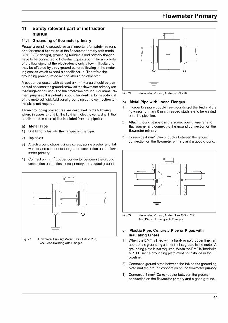
11.1 Grounding of flowmeter primaryProper grounding procedures are important for safety reasons and for correct operation of the flowmeter primary with model DP46F (Ex-design), grounding terminals and primary flanges have to be connected to Potential Equalization. The amplitude of the flow signal at the electrodes is only a few millivolts and may be affected by stray ground currents flowing in the meter-ing section which exceed a specific value. Therefore the grounding procedure described should be observed.
A copper-conductor with at least a 4 mm2 area should be con-nected between the ground screw on the flowmeter primary (on the flange or housing) and the protection ground. For measure-ment purposed this potential should be identical to the potential of the metered fluid. Additional grounding at the connection ter-minals is not required.
Three grounding procedures are described in the following where in cases a) and b) the fluid is in electric contact with the pipeline and in case c) it is insulated from the pipeline.
a) Metal Pipe1) Drill blind holes into the flanges on the pipe.
2) Tap holes.
3) Attach ground straps using a screw, spring washer and flat washer and connect to the ground connection on the flow-meter primary.
4) Connect a 4 mm2 copper-conductor between the ground connection on the flowmeter primary and a good ground.
b
b) Metal Pipe with Loose Flanges1) In order to assure trouble free grounding of the fluid and the
flowmeter primary 6 mm threaded studs are to be welded onto the pipe line.
2) Attach ground straps using a screw, spring washer andflat washer and connect to the ground connection on theflowmeter primary.
3) Connect a 4 mm2 Cu-conductor between the ground connection on the flowmeter primary and a good ground.
c) Plastic Pipe, Concrete Pipe or Pipes with Insulating Liners
1) When the EMF is lined with a hard- or soft rubber liner, an appropriate grounding element is integrated in the meter. A grounding plate is not required. When the EMF is lined with a PTFE liner a grounding plate must be installed in the pipeline.
2) Connect a ground strap between the tab on the grounding plate and the ground connection on the flowmeter primary.
3) Connect a 4 mm2 Cu-conductor between the ground connection on the flowmeter primary and a good ground.
Fig. 27 Flowmeter Primary Meter Sizes 150 to 250, Two Piece Housing with Flanges
Fig. 28 Flowmeter Primary Meter > DN 250
Fig. 29 Flowmeter Primary Meter Size 150 to 250Two Piece Housing with Flanges
33
Flowmeter Primary
General note concerning groundingFor plastic pipelines or pipelines lined with an insulating liner the ground connection is made to a grounding plate or a groun-ding electrode. Flowmeter primaries with hard rubber liners incorporate a conductive element in the flange area for groun-ding. In this design grounding plates or electrodes are not required. When stray voltages exist in the pipeline and a flow-meter primary with a PTFE liner is installed grounding plates should be installed at both ends of the flowmeter primary.
Fig. 30 Flowmeter Primary Meter Sizes 150 to 250, Two Piece Housing with Fixed Flanges
Fig. 31 Meter with an Integrated Conductive Element in the Linerfor Grounding
34
Flowmeter Primary
11.2 Power supply Connection The power supply, as specified on the instrument tag, is connected to the converter terminals L (phase) and N (neutral) over a main fuse and a main switch. The electromagnetic flowmeter primary is connected to the converter with the signal- and reference voltage cable and the excitation cable.
Pay attention to safety-notes section 9.4.
11.3 Signal- and excitation cableThe magnet coils in the flowmeter primary are supplied from the remote mounted converter over terminals MO/NO/MU/NU (excitation cable see Interconnection Diagram).
The signal cable is connected to the flowmeter primary and the converter as shown in the Interconnection Diagram. The flow direction indicated by the arrow on the flowmeterprimary corresponds to the forward flow direction.
Shield 3 is connected to the common potential of the flowmeter primary, which is connected to ground per VDE 0100.
Pay attention to safety-notes section 9.4.
NoteIf plant conditions make it impossible to avoid proximity to elec-trical machinery and switch gear equipment, it is recommended to route the signal cable in a grounded metal conduit.
11.3.1 Signal and excitation Cable ConstructionThe signal cable conducts signals of only a few millivolts and therefore should be routed in the shortest manner. The maxi-mum allowable signal cable length is 50 m. The cables should not be routed in the vicinity of large electrical machinery and switch gear equipment which could induce stray fields, pulses and voltages.
The signal cable design includes a steel and copper shield around the signal leads. The shields around the individual signal leads are "Driven Shields" for the signal transmission.
PVC Jacket, white
Woven Steel Wire Shield ∅ 0.15 mm
Woven Copper-Wire Shield ∅ 0.13 mm
PVC Jacket, white
Woven Copper-Wire Shield, ∅ 0.1 mm
Signal lead
Insulation Color Connection Terminalred MOblue MUwhite do not connect
red 2orange 3Eyellow 4Egreen 5Eblue 6Eblack 7Ewhite 8Eviolet 9E
Fig. 33 Signal Cable Construction D173D021U01
35
Flowmeter Primary
11.3.2 Interconnection of flowmeter primary and converter
The leads in the signal cable should be routed to the terminals in the shortest way possible. Loops are to be avoided.
Use care when replacing and tightening the housing cover. Check to make sure that the gasket is seated properly. Only then will Protection Class IP 67 be assured.
When installing the cable to the flowmeter primary a water trap should be provided.
The temperature of the primary´s surface might exceed 70 °C depending on the temperature of the fluid inside. Signal- and excitation cable shouldn´t be in contact.
Stripping of signal- and excitation cable for model DP46F (Ex-design)
The insulation is ex-relevant.The lengths of the insolation have to be complied.
Excitation cable Signal cable
Terminal Designations Connection1+2+3E to 9E3MU+NU+MO+NO
SE/PA
Flow signal leadsInner cable shields (copper)Connections for magnetic fieldexcitation (from converter)Outer cable shields
Fig. 34 Connection box of the Flowmeter Primary
Signal cable
Fig. 35 Insulation of signal cables
Pos. 10 Wire end ferrule 0,75 mm2
11 Wire end ferrule 2,5 mm2
50-54 shrink down hose
Excitation cable
Fig. 36 Insulation of excitation cables
36
Flowmeter Primary
AttentionThe excitation circuit is liable to shock. Don´t touch the terminals MU, NU, MO, NO if the power supply is on.The primary is to be connected to the converter by use of ABB Automation Products signal- and excitation ca-ble only. Refer to fig. 24 and 33/34. For safety reasons the primary model DP41, is also to be connected to protec-tion ground. Wit primary model DP46 (Ex-design), grounding terminals and primary-flanges have to be connected to potential equalisation.
11.3.3 Connection for protection class IP 68For flowmeters primary with protection class IP 68, the maxi-mum flooding height is 5 m. The supplied cable (part no. D173D025U01) fulfills all submersion requirements
Fig. 381 Max. flooding height 5 m
11.3.3.1 Connection1. Use the signal cable (part no. D173D025U01) to connect the
flowmeter primary and the transmitter.2. Connect the signal cable in the terminal box of the flowmeter
primary.3. Route the cable from the terminal box to over the maximum
flooding height of 5 m.4. Tighten the cable gland.5. Carefully seal the terminal box. Make sure the gaskets for
the cover are seated properly.
Caution - Potential damage to parts!The jacket of the signal cable must not be damaged. Otherwise, the protection class IP 68 for the flowmeter primary cannot be ensured.
ImportantAs an option, the flowmeter primary can be ordered with signal cable already connected to the terminal box.
11.3.3.2 Potting the connection boxIf the terminal box is to be potted on-site, a special potting com-pound can be ordered separately (order no. D141B038U01). Potting is only possible if the flowmeter primary is installed hor-izontally.
Observe the following instructions during work activity:
Warning - General hazards!The sealing compound is toxic. Observe all relevant safety measures.Risk notes: R20, R36/37/38, R42/43Harmful by inhalation. Avoid direct skin contact. Irritating to eyes.Safety advice: P4, S23-A, S24/25, S26, S37, S38Wear suitable protective gloves and ensure sufficient ventilation.Follow the instructions that are provided by the manu-facturer prior to starting any preparations.
Preparation• Complete the installation before beginning sealing activities
in order avoids moisture penetration. Before starting, check all the connections for correct fitting and stability.
• Do not overfill the terminal box. Keep the potting compound away from the O-ring and the seal/groove (see below).
• Prevent the potting compound from penetrating a conduit if an NPT 1/2" thread is used.
Procedure1. Remove the outer wrapper by cutting with scissors where
indicated.2. Remove the rubber end caps from the centre clip. Remove
the clip.3. Knead both components thoroughly until a uniformly blend is
reached.4. Cut open the bag at a corner.5. Carefully fill the terminal box with potting compound until the
connecting cable is covered.6. Wait before closing the cover in order to allow the compound
to dry, and to release any possible gas.7. Ensure that the packaging material and the drying bag are
11.3.4 Signal Cable Connections at the ConverterBoth cables are connected to the PARTI-MAG II converter prior to shipment. If the cables need to be shortened, then we recom-mend rolling up the cable.
11.3.4.1 Field Mount Housing ConnectionsThe signal cable should be prepared as shown in Fig. 32. All shields for the individual conductors are to be covered with suit-able insulating tubing since they are at different potentials.
The outermost shield of the signal cable is not connected at the converter. The shield is electrically connected to the con-verter housing by a plug-in brass bushing through the special PG-connector 16/21.
Before opening the housing the power supply must be turned off.
1
2
3
4
Fig. 40
Fig. 41 Converter field housing design
38
Converter Model FXP4000-XP2 (50XP2000)
11.3.4.2 19”-Rack Mount ConnectionSignal- and excitation cable should be prepared as shown in Fig. 31. The length L should be prepared in accordance to the requirements at the location where the converter is to be in-stalled. To shield against magnetic picup the cable incorporates and steel shield. At location X the insulation is to beremoved and the steel shield is to be connected to ground as shown in Fig. 31.
NoteThe copper shield of the excitation cable is not used. Therefore it is to be covered with is suitable insolution tubing.
Bracket assures electrical con-nection to a good ground avail-able at the customers location. (For example in the panel where the converter should be installed in
Excitation cable
Signal cable
Fig. 42
violetbrown
orangeblueyellowgreen
Cu-shield
redblackwhite
violetbrown
orange
yellowgreen
Cu-shield
redblack
white
white violetblack
Cu-shield
Stl-shield
orange
yellowgreen
blue
red
brown
Stl-shield Stl-shield
Flowmeter Primary Converter
Stl-shield Stl-shield
blue
red
white
blue
red
white
blue
red
white
Stl-shield
Cu-shield
blue
x
Signal cable
Excitation cable
shrinking down hose
wire end ferrule
Fig. 43
39
Flowmeter Primary
11.4 Interconnection Diagramm11.4.1 Primary DP41F and converter FXP4000-XP2 (50XP2000)
1) Supply Power, see Instrument Tag2) Contact Input (optocoupler),16 V < U < 30 V, Ri = 2000 Ω, Function software selectable for:
a) External zero returnb) External totalizer reset
Optocoupler contact input control- passive, over contact (closer). Install jumper G2/g2 for this mode- active, over terminals G2/22 or G2/31. Jumper is not to be installed.
3) Scaled Pulse Output, active 24 V DC, load > 150 Ω, fmax < 5 kHzTerminals g2 and Va, Function 9 and 11 forwardTerminals g2 and Vc, Function 9 and 11 R reverse
4) Scaled Pulse Output, passive, optocoupler,5 V < UCE ≤ 25 V DC, 5 mA < ICE < 200 mA; fmax 5 kHzTerminals Va and Vb, Function 55 and 56 forwardTerminals Vc and Vd, Function 57 and 58 reverse
8) Alarm Output, relay contact < 3 W; < 250 mA; < 30 V DC, opens at alarm, Terminals V5, V6, Function 39/40 or
Alarm Output, optocoupler, same specifications in 8), opens at alarm,Terminals V5, V6, Function E9/C9
9) Shielded Signal Cable, connected to converter when shipped10) Shielded Excitation Cable, connected to converter when shipped
Note:1) When using data link RS 485 a shielded data cable with individually twisted pairs is recommended.
7Eblack
3Eorange
4Eyellow5E
green
6Eblue
2red
1brown
8Ewhite
9Eviolet
MUblue
SEStl-shield
3Cu-shield
MOred
SEStl-shield
no connection
no connection
Excitation cable
Signal cable
Colour-Code
white
Cu-shield
L+
G2
L- PE
1L11L2 PEL N PE 22 31 U2 g2 Va Vb Vc
11R119
58575655
Vd – + g2 V1 V2 V3 V4
R+R-T+T-
P1 P2 P3 P4 V5 V6
39 40
C9E9
MONO MU NU 9E 9S 8E 8S 7E 7S 6E 6S 5E 5S 4E 4S 3E 3S 2 2S 1 1S 3
9E 8E 7E 6E 5E 4E 3E 2 1 3 SEMONO MU NUSE
Primary DP41F
Converter Model 50XP2000
1) 2)
3)4)
5)
6)
7) 8)10) 9)
Fig. 44 Signal- and Coil Excitation Cable Connections
40
Flowmeter Primary
11.4.2 Primary DP46F (ex-design) and converter FXP4000-XP2 (50XP2000)
1) Supply Power, see Instrument Tag2) Contact Input (optocoupler),16 V < U < 30 V, Ri = 2000 Ω, Function software selectable for:
a) External zero returnb) External totalizer reset
Optocoupler contact input control- passive, over contact (closer). Install jumper G2/g2 for this mode- active, over terminals G2/22 or G2/31. Jumper is not to be installed.
3) Scaled Pulse Output, active 24 V DC, load > 150 Ω, fmax < 5 kHzTerminals g2 and Va, Function 9 and 11 forwardTerminals g2 and Vc, Function 9 and 11 R reverse
4) Scaled Pulse Output, passive, optocoupler,5 V < UCE ≤ 25 V DC, 5 mA < ICE < 200 mA; fmax 5 kHzTerminals Va and Vb, Function 55 and 56 forwardTerminals Vc and Vd, Function 57 and 58 reverse
8) Alarm Output, relay contact < 3 W; < 250 mA; < 30 V DC, opens at alarm, Terminals V5, V6, Function 39/40 or
Alarm Output, optocoupler, same specifications in 8), opens at alarm,Terminals V5, V6, Function E9/C9
9) Shielded Signal Cable, connected to converter when shipped10) Shielded Excitation Cable, connected to converter when shipped
Note:1) When using data link RS 485 a shielded data cable with individually twisted pairs is recommended.
The rated voltage UM for the in- and outputs is 60 V
7Eblack
3Eorange
4Eyellow5E
green
6Eblue
2red
1brown
8Ewhite
9Eviolet
MUblue
SEStl-shield
3Cu-shield
MOred
SEStl-shield
no connection
no connection
Excitation cable
Signal cable
Colour-Code
white
Cu-shield
L+
G2
L-
1L11L2L N 22 31 U2 g2 Va Vb Vc
11R119
58575655
Vd – + g2 V1 V2 V3 V4
R+R-T+T-
P1 P2 P3 P4 V5 V6
39 40
C9E9
MONO MU NU 9E 9S 8E 8S 7E 7S 6E 6S 5E 5S 4E 4S 3E 3S 2 2S 1 1S 3
9E 8E 7E 6E 5E 4E 3E 2 1 3 SEMONO MU NUSE
Primary DP46F
Converter Model 50XP2000
PA
Functionalground
non hazardous area
hazardous area(Zone 1)
1) 2)
3)4)
5)
6)
7) 8)10) 9)
PotentialEqualization
Fig. 45 Signal- and Coil Excitation Cable Connections
41
Converter Model FXP4000-XP2 (50XP2000)
11.4.3 Safety-notes
NoteDangerous electrical currents are present in the flow-meter primary and the converter. You must therefore turn off the supply power before opening the housing. Work activities on open meters should only be per-formed by trained personnel.
• Flowmeter primary and converter consist of electrical circuits that are liable to shock. Turn off the power supply prior opening the housing. All repair or service work is to be performed by qualified personnel.
• The primary and the converter are to be connected to protection ground. With the ex-design the primary is to be connected to potential equalization.
• The supply power conducter cress section must be in accord with IEC227 or IEC245.
• The converter is tobe connected to the supply power over a main fuse and a main switch. The switch should be located near the converter. A tag on the switch is recommended to identify the switch belonging to the converter.
• The primary is connected to the converter by use of ABB Automation Products signal- and excitation cable only. The interconnection must be in accord with fig. 30 und 31.
• To assure a safe operating of the flowmeter the installation has to be in accordance with this instruction manual an the notes that are made.
Note Connection of peripheralExcept the supply power circuit and the excitation circuit the other signal output circuits of the converter are not liable to shock. Therfor peripherals that are also not liable to shock are permitted to be connected to the converter.
42
Converter Model FXP4000-XP2 (50XP2000)
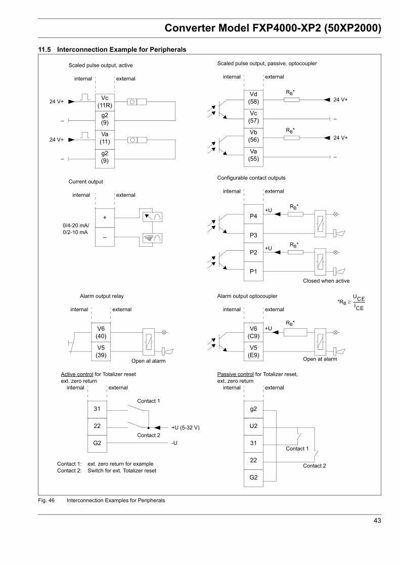
11.5 Interconnection Example for Peripherals
Vc(11R)
g2(9)
Va(11)
g2(9)
–
24 V+
internal external
24 V+
–
Scaled pulse output, active
Vd(58)
Vc(57)
Vb(56)
Va(55)
–
24 V+
internal external
24 V+
–
Scaled pulse output, passive, optocoupler
RB*
RB*
+
–
0/4-20 mA/0/2-10 mA
internal external
Current output
P4
P3
P2
P1
internal external
Configurable contact outputs
RB*
RB*+U
+U
Closed when active
V6(40)
V5(39)
internal external
Alarm output relay
Open at alarm
V6(C9)
V5(E9)
internal external
Alarm output optocoupler
RB*+U
Open at alarm
*RB ≥ UCEICE-------------
31
22
internal external
Active control for Totalizer resetext. zero return
G2
Contact 1
Contact 2
Contact 1: ext. zero return for example Contact 2: Switch for ext. Totalizer reset
+U (5-32 V)
-U
g2
U2
31
22
internal external
Passive control for Totalizer reset,ext. zero return
G2
Contact 1
Contact 2
Fig. 46 Interconnection Examples for Peripherals
43
Converter Model FXP4000-XP2 (50XP2000)
11.6 Electrical specification of the converter (supply power, power consumption etc)
Flow RangeContinuous, 0.5 m/s to 9.99 m/s
Conductivity≥ 50 μS/cm
Max. Conductivity10.000 μS/cm
Response Time 0-99 % response to a step change (corresp. to 5 τ)≥ 10 s
DampingSetable to 200 s
Supply Power115/230 V AC ± 10 %24 V AC ± 10 %50/60 Hz ± 6 %Ripple < 1.5 Vp
Magnetic Field Supply6 1/4 Hz, 7 1/2 Hz (50/60 Hz supply power)
Power DN 150 to DN 2000< 60 VA (flowmeter primary and converter)
Ambient Temperature-20 ... 50 °C (-4 ... 122 °F)
Protection Class per EN 60529IP 65 for field mount housingIP 00 for 19”-Rack Mount
ConstructionField mount housing in stainless steel19”-Rack Mount, 167 mm deep, 28 TE, 3 HE
Electrical ConnectionsScrew terminals5 x cable connectors Pg 13.51 x cable connectors Pg 16/21 for signal cable
WeightField mount housing ca. 9.3 kg19”-Rack Mount ca. 2.8 kg
Signal Cable / Excitation CableThe max. cable length between the flowmeter primary and the converter is 50 m. The signal and excitation cables are preassembled and connected to the converter prior to shipment (field mount housing version). Ordering number see section 8.2.
Display2 x 16-character dot matrix display in Super-Twist technology with LED background lighting. In the 1st line the flowrate direction and its instantaneous value are displayed in % or in the selected engineering units. Optionally the instantaneous fill height can be displayed. In the 2nd line the integrated flow volume value is displayed in engineering units. There is a separate totalizer for each flow direction, 7 digit with overflow counter.
Parameter EntryEntries are made from the keypad, menu controlled in a clear text dialog. All entry parameters including the totalizer values are stored for a 10 year period in an EEPROM. The meter location specific parameters can be uploaded into an exchanged converter by pressing a single button
Forward-/Reverse Flow MeteringAn arrow in the display and a contact output (optocoupler) for an external signal indicate the existing flow direction.
11.7 Specification of the input signals11.7.1 External Zero ReturnAll output signals can be turned off over an external passive or active contact (closure).
Optocoupler: 16 V ≤ UCE ≤ 30 V DC, Ri = 2000 Ω
11.7.2 External Totalizer ResetThe internal totalizer values can be reset over an external passive or active contact (closure).
Optocoupler: 16 V ≤ UCE ≤ 30 V DC, Ri = 2000 Ω
Fig. 47 Converter Field Mount Housing and 19 “-Rack Mount
→ V 70.01 %→ V 10350 m3
44
Converter Model FXP4000-XP2 (50XP2000)
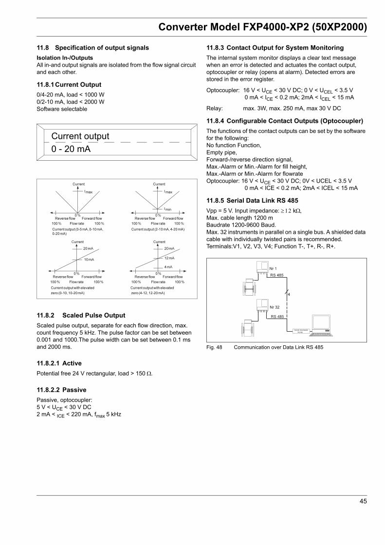
11.8 Specification of output signalsIsolation In-/OutputsAll in-and output signals are isolated from the flow signal circuit and each other.
11.8.2 Scaled Pulse OutputScaled pulse output, separate for each flow direction, max. count frequency 5 kHz. The pulse factor can be set between 0.001 and 1000.The pulse width can be set between 0.1 ms and 2000 ms.
11.8.2.1 ActivePotential free 24 V rectangular, load > 150 Ω.
11.8.2.2 PassivePassive, optocoupler:5 V < UCE < 30 V DC2 mA < ICE < 220 mA, fmax 5 kHz
11.8.3 Contact Output for System MonitoringThe internal system monitor displays a clear text message when an error is detected and actuates the contact output, optocoupler or relay (opens at alarm). Detected errors are stored in the error register.
Optocoupler: 16 V < UCE < 30 V DC; 0 V < UCEL < 3.5 V 0 mA < ICE < 0.2 mA; 2mA < ICEL < 15 mA
Relay: max. 3W, max. 250 mA, max 30 V DC
11.8.4 Configurable Contact Outputs (Optocoupler)The functions of the contact outputs can be set by the software for the following:No function Function,Empty pipe,Forward-/reverse direction signal,Max.-Alarm or Min.-Alarm for fill height,Max.-Alarm or Min.-Alarm for flowrateOptocoupler: 16 V < UCE < 30 V DC; 0V < UCEL < 3.5 V
0 mA < ICE < 0.2 mA; 2mA < ICEL < 15 mA
11.8.5 Serial Data Link RS 485Vpp = 5 V. Input impedance: ≥ 12 kΩ,Max. cable length 1200 mBaudrate 1200-9600 Baud.Max. 32 instruments in parallel on a single bus. A shielded data cable with individually twisted pairs is recommended.Terminals:V1, V2, V3, V4; Function T-, T+, R-, R+.
Current output0 - 20 mA
Fig. 48 Communication over Data Link RS 485
45
Converter Model FXP4000-XP2 (50XP2000)
11.9 Start-up 11.9.1 Inspection Before installing the electromagnetic flowmeter system check for mechanical damage due to possible mishandling during shipment. All claims for damage are to be made promptly to the shipper before installing the flowmeter.
11.9.2 Installation of the converter 50XP2000The housings for wall mounted converters are designed for Protection Class IP 65. The lower section of the housing is mounted using 4 screws. The mounting location should be essentially free of vibration. The specified temperature limits from -20 °C ... 50 °C (-4 ... 122 °F) are to be observed. Note that the maximum signal cable length between the flowmeter primary and the converter of 50 m may not be exceeded. The mounting location should be selected accordingly. It is also important when selecting a mounting location that the converter not be exposed to direct sunlight.
11.9.3 Converter Electrical ConnectionsThe supply power, as specified on the instrument tag, is connected to the converter terminals L (phase) and N (neutral) or 1L1 and 1L2 over a main fuse and a mains switch. The supply power conductor cross section and the main fuse must be compatible. The power consumption is maximum 60 VA (converter and flowmeter primary). The connections are made in accord with Interconnection Diagram section 9.4Pay attention to safety-notes made in section 9.4
11.9.4 Start-Up-ChecklistFollow the start-up procedure described below after the assembly and installation of the flowmeter primary and convert-er have been completed.
The supply power is turned off!
Check that the flow direction agrees with the direction indicated by the arrow on the flowmeter primary housing.
• Check the grounds per section 9.1.• Check that the connections agree with the Interconnection
Diagram section 9.4.• Check that the supply power agrees with the specifications
on the Instrument Tag.• Check that the ambient temperature agrees with values
listed in the Specifications• Check that the coordination between the flowmeter primary
and the converter is correct. Instruments with the same end characters A1 and B1 or A2 and B2 on the Instrument Tags belong together.
• Close the connection box of the primary and the connection box of the converter.
Turn on the supply power.
Check the contrast setting of the display. A small screwdriver can be used to adjust the contrast of the display for the ambient conditions. The adjustment potentiometer is located on the front plate of the converter.
A few parameters must first be selected or set in order to operate the system. The flow range is automatically set to10 m/s. Enter the desired flow ranges for the forward and reverse flow directions in the appropriate engineering units.
In the "Submenu Current output" select the required current output range (0-20 mA/4-20 mA). If the converter includes an active or passive pulse output option, the pulses per unit must set for the selected engineering units. The pulse width for an external counter or for processing in a computer can be select-ed between 0.1 ms and 2000 ms.
After completion of the start-up procedure all parameters should be stored in the EEPROM that is located on the terminal board. Therfore selected the submenu “Stored data inext. EEPROM”. When the converter is exchanged the parameters can be uploaded into the new converter.
The data and parameters entered and the options included in the converter can be recorded on the last page of this Instruction Manual for service or repair reference.
46
Converter Model FXP4000-XP2 (50XP2000)
11.10 Maintenance11.10.1 PrimaryThe flowmeter primary is essential maintenance free. Monitor on a yearly basis the ambient conditions (humidity, air circula-tion), the integrity of the flange gaskets, cable entries and cover screws, operational safety of the supply power, lightning protection and the protection ground connections.
NoteAll repair or service work is to be performed by qualified personnel.
Please review the Notes (Hazardous Material Law) onthe yellow page if the flowmeter primary is to be returned to the Abb Automation Products factory for repair.
Notes Regarding the Opening of the HousingThe following notes must be observed if the converter housing is opened:
• All interconnection leads must be potential free.• The EMC-Protection is limited when the housing is open.• The temperature of the primary´s surface might exceed
70 °C (158 °F).
Spare partsFore funktional and safety reason original ABB Automation Products spare parts are to be used.
47
Flowmeter Primary
11.11 Flowmeter System Error Search
NoteFor Error and status messages refer to section 5.
NoteWhen the housing cover is removed and the supplypower turned on physical contact and EMC protection are voided.
Turn off supply power before removing the housing cover. The temperature of the primary´s surface might exceed 70 °C (158 °F). Pay attention to safety notes in section 9.10.
Service work is to be performed by qualified personnel.
Checks of the meter system are made after the assembly and installation of the flowmeter primary and converter is complete.Is the supply power in accord with the specifications on the converter Instrument Tag?
no Set jumpers for required voltage (see Analog- and Driver boards).
yesAre the flowmeter primary and converter installed in the correct location? (Protection Class, temperature, vibration, cable length, cable type, flow direction arrow, sunlight on display).
no Check allowable installation conditions (see Specifications).
yesAre the interconnections in agreement with the Interconnection Diagram? Are the ground connections on the flowmeter primary correctly installed, the protection ground of the line connected to the converter?
no Check connections against Interconnection Diagram (see Page 32).
yesIs the supply power within the allowable tolerances at the terminals? Terminals L, N: AC voltage. tolerance +10% to -10%; 1L1, 1L2: low voltage AC, tolerance +10 % to -10 %.
no Provide supply power within tolerances.
yesIs the flowmeter primary partially filled with liquid? no Partially fill flowmeter primary.
yesAre the present flow direction (>F for forward, < R for reverse) and the instantaneous flowrate value in percent or in engineering units displayed? Does the present flow-rate value correspond to the display and output signals?
no Fuse defective, conductivity < 50 µS/cm. Defective flowme-ter primary or converter.