48
Operating Instruction 42/14-42-EN Thermal Mass Flowmeter Sensyflow FMT700-P for air, test benches

Operating Instruction 42/14-42-EN
Thermal Mass Flowmeter Sensyflow FMT700-P
for air, test benches

Blinder Text
2 Sensyflow FMT700-P 42/14-42-EN
Thermal Mass Flowmeter Sensyflow FMT700-P
Operating Instruction 42/14-42-EN
07.2017
Rev. H
Original instruction
Manufacturer: ABB Automation Products GmbH Measurement & Analytics
Dransfelder Straße 2 D-37079 Göttingen Germany Tel.: +49 551 905-0 Fax: +49 551 905-777
Customer service center
Phone: +49 180 5 222 580 [email protected]
© Copyright 2017 by ABB Automation Products GmbH Subject to changes without notice
This document is protected by copyright. It assists the user in safe and efficient operation of the device. The contents of this document, whether whole or in part, may not be copied or reproduced without prior approval by the copyright holder.
Contents

Contents
42/14-42-EN Sensyflow FMT700-P 3
1 Safety ............................................................................................................................................................. 4
1.1 Intended use ................................................................................................................................................... 4
1.2 Target groups and qualifications .................................................................................................................... 4
1.3 Warranty provisions ........................................................................................................................................ 4
1.4 Note symbols .................................................................................................................................................. 5
1.5 Name plates ................................................................................................................................................... 5
1.6 Safety instructions for electrical installation ................................................................................................... 6
1.7 Returning devices ........................................................................................................................................... 6
1.8 Integrated management system ..................................................................................................................... 7
1.9 Disposal .......................................................................................................................................................... 7
1.9.1 Information on WEEE Directive 2012/19/EU (Waste Electrical and Electronic Equipment) ................... 7
2 Device description ....................................................................................................................................... 8
2.1 Front view ....................................................................................................................................................... 8
2.2 Rear view........................................................................................................................................................ 8
2.2.1 Supply power .......................................................................................................................................... 9
2.2.2 D-SUB connector .................................................................................................................................... 9
2.2.3 BNC outputs and sensor connection .................................................................................................... 10
3 Electrical connections ............................................................................................................................... 11
3.1 BNC outputs and flowmeter sensor connection ........................................................................................... 11
3.2 SLOT 1: D-SUB connection „Serial Output“ ................................................................................................. 11
3.3 SLOT 3: D-SUB connection „Totalizer“ ........................................................................................................ 12
3.4 SLOT 4: D-SUB connection „Analog Outputs“ ............................................................................................. 13
4 Commissioning .......................................................................................................................................... 15
5 Operation..................................................................................................................................................... 16
5.1 Supply / evaluation unit ................................................................................................................................ 16
5.2 Display unit (Display) .................................................................................................................................... 17
5.3 Options ......................................................................................................................................................... 17
5.3.1 Adjustable measuring rate .................................................................................................................... 17
5.3.2 Fast measuring rate .............................................................................................................................. 18
5.3.3 Analog outputs ...................................................................................................................................... 19
5.4 Temperature measurement .......................................................................................................................... 21
5.5 Operation with two flowmeter sensors ......................................................................................................... 22
6 Communication .......................................................................................................................................... 23
6.1 Digital interfaces ........................................................................................................................................... 23
6.1.1 Serial interface ...................................................................................................................................... 23
6.1.2 Totalizer (integrator function) ................................................................................................................ 29
7 Measuring setup and installation ............................................................................................................. 32
8 Specifications ............................................................................................................................................. 34
9 Dimensions ................................................................................................................................................. 36
9.1 Flowmeter sensor Sensyflow FMT700-P, DN 25 ......................................................................................... 36
9.2 Flowmeter sensor Sensyflow FMT700-P, DN 50 ... DN 200 ........................................................................ 37
9.3 Supply / evaluation unit ................................................................................................................................ 38
9.4 Accessories .................................................................................................................................................. 38
10 Appendix ..................................................................................................................................................... 45
10.1 Decommissioning and packaging ................................................................................................................ 45
10.2 Approvals and certifications ......................................................................................................................... 45
10.3 Return form .................................................................................................................................................. 46
Safety
4 Sensyflow FMT700-P 42/14-42-EN
1 Safety
You must read these instructions carefully prior to installing and commissioning the device.
These instructions are an important part of the product and must be kept for future reference.
These instructions are intended as an overview and do not contain detailed information on all designs for this product or every possible aspect of installation, operation and maintenance.
For additional information or if specific problems occur that are not discussed in these instructions, contact the manufacturer.
The content of these instructions is neither part of any previous or existing agreement, promise or legal relationship nor is it intended to change the same.
This product is built based on state-of-the-art technology and is operationally safe. It has been tested and left the factory in perfect working order from a safety perspective. The information in the manual must be observed and followed in order to maintain this state throughout the period of operation.
Modifications and repairs to the product may only be performed if expressly permitted by these instructions.
Only by observing all of the safety instructions and all safety/warning symbols in these instructions can optimum protection of both personnel and the environment, as well as safe and fault-free operation of the device, be ensured.
Information and symbols directly on the product must be observed. They may not be removed and must be fully legible at all times.
1.1 Intended use
Mass flow measurement of air in closed pipelines.
The device is designed for use exclusively within the values stated on the name plate and in the technical specifications (see the section titled "Specifications" on page 34).
1.2 Target groups and qualifications
Installation, commissioning, and maintenance of the product may only be performed by trained specialist personnel who have been authorized by the plant operator accordingly. The specialist personnel must have read and understood the manual and must comply with its instructions.
The operating company must strictly observe the applicable national regulations relating to the installation, function testing, repair, and maintenance of electrical products.
1.3 Warranty provisions
Using the device in a manner that does not fall within the scope of its intended use, disregarding this instruction, using underqualified personnel, or making unauthorized alterations releases the manufacturer from liability for any resulting damage. This renders the manufacturer's warranty null and void.
Safety
42/14-42-EN Sensyflow FMT700-P 5
1.4 Note symbols
IMPORTANT (NOTE)
This symbol indicates operator tips, particularly useful information, or important information about the product or its further uses. It does not indicate a dangerous or damaging situation.
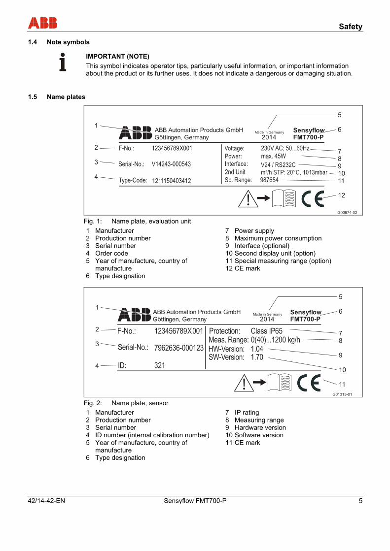
1.5 Name plates
Fig. 1: Name plate, evaluation unit
1 Manufacturer 2 Production number 3 Serial number 4 Order code 5 Year of manufacture, country of
manufacture 6 Type designation
7 Power supply 8 Maximum power consumption 9 Interface (optional) 10 Second display unit (option) 11 Special measuring range (option) 12 CE mark
Fig. 2: Name plate, sensor
1 Manufacturer 2 Production number 3 Serial number 4 ID number (internal calibration number) 5 Year of manufacture, country of
manufacture 6 Type designation
7 IP rating 8 Measuring range 9 Hardware version 10 Software version 11 CE mark
G00974-02
Voltage:
ABB Automation Products GmbH
FMT700-P2014Made in Germany
Sp. Range:
230V AC; 50...60Hz
Power:
2nd Unit
987654
X
Type-Code:
max. 45W
Göttingen, Germany
001
V14243-000543Serial-No.:
Sensyflow
123456789F-No.:
1211150403412
Interface: V24 / RS232Cm³/h STP: 20°C, 1013mbar
1
2
3
4
5
6
7891011
12
G01315-01
ABB Automation Products GmbH
FMT700-P
ID:
2014Made in Germany
Meas. Range:
Sensyflow
0(40)...1200 kg/h
Göttingen, Germany
F-No.: 001X
Serial-No.:
Protection: Class IP65
321
7962636-000123
123456789
HW-Version:SW-Version:
1.041.70
1
2
3
4
5
6
78
9
10
11

Safety
6 Sensyflow FMT700-P 42/14-42-EN
1.6 Safety instructions for electrical installation
The electrical connection may only be made by authorized specialist personnel according to the electrical plans.
The electrical connection information in the manual must be observed; otherwise, the electrical protection type may be adversely affected.
Ground the measurement system according to requirements.
1.7 Returning devices
Use the original packaging or a secure transport container of an appropriate type if you need to return the device for repair or recalibration purposes. Fill out the return form (see the Appendix) and include this with the device.
The EU Directive governing hazardous materials dictates that the owners of any hazardous waste are also responsible for disposing of it.
All devices delivered to the manufacturer must be free from any hazardous materials (acids, alkalis, solvents, etc.).
Pipe components and flowmeter sensors contain hollow spaces. If they have been used in conjunction with hazardous materials, they must therefore be rinsed out in order to neutralize any such substances.
The owner will be charged for any costs incurred as a result of the device not having been adequately cleaned or of any failure to dispose of hazardous materials. The manufacturer reserves the right to return a contaminated device.
Please
Please contact Customer Center Service acc. to page 2 for nearest service location.

Safety
42/14-42-EN Sensyflow FMT700-P 7
1.8 Integrated management system
ABB Automation Products GmbH operates an integrated management system, consisting of:
• Quality management system to ISO 9001,
• Environmental management system to ISO 14001,
• Occupational health and safety management system to BS OHSAS 18001 and
• Data and information protection management system.
Environmental awareness is an important part of our company policy.
Our products and solutions are intended to have minimum impact on the environment and on people during manufacturing, storage, transport, use, and disposal.
This includes the environmentally-friendly use of natural resources. We conduct an open dialog with the public through our publications.
1.9 Disposal
This product is manufactured from materials that can be reused by specialist recycling companies.
1.9.1 Information on WEEE Directive 2012/19/EU (Waste Electrical and Electronic Equipment)
This product is not subject to WEEE Directive 2012/19/EU or relevant national laws (e.g., ElektroG in Germany).
The product must be disposed of at a specialist recycling facility. Do not use municipal garbage collection points. According to the WEEE Directive 2012/19/EU, only products used in private applications may be disposed of at municipal garbage facilities. Proper disposal prevents negative effects on people and the environment, and supports the reuse of valuable raw materials.
If it is not possible to dispose of old equipment properly, ABB Service can accept and dispose of returns for a fee.
Device description
8 Sensyflow FMT700-P 42/14-42-EN
2 Device description
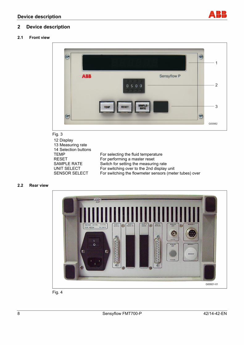
2.1 Front view
Fig. 3
12Display 13Measuring rate 14Selection buttons
TEMP RESET SAMPLE RATE UNIT SELECT SENSOR SELECT
For selecting the fluid temperature For performing a master reset Switch for setting the measuring rate For switching over to the 2nd display unit For switching the flowmeter sensors (meter tubes) over
2.2 Rear view
Fig. 4
G00982
1
2
3
G00931-01

Device description
42/14-42-EN Sensyflow FMT700-P 9
2.2.1 Supply power
Master On / Off switch
Fuse slot
Socket for 3-pin power plug with internal fuse (see note on rear)
Notice - Potential damage to parts!
Check whether the voltage specified on the name plate matches the line voltage.
G00932
Fig. 5
2.2.2 D-SUB connector
SLOT 1 25-pin D-SUB connector: "Serial output" SLOT 3 25-pin D-SUB connector: "Totalizer" SLOT 4
25-pin D-SUB connector "Analog outputs"
G00933
Fig. 6

Device description
10 Sensyflow FMT700-P 42/14-42-EN
2.2.3 BNC outputs and sensor connection
ANALOG OUT 0 ... 10 V Analog output voltage via BNC socket ANALOG OUT 0 (4) ... 20 mA Analog output current via BNC socket SENSOR 1 Connection for flowmeter sensor 1 (7-pin) SENSOR 2 Connection for flowmeter sensor 2 (7-pin) for operation with 2 flowmeter sensors
G00934
Fig. 7

Electrical connections
42/14-42-EN Sensyflow FMT700-P 11
3 Electrical connections
3.1 BNC outputs and flowmeter sensor connection
BNC outputs Current output: 0 (4) ... 20 mA Voltage output: 0 ... 10 V
G00923 Flowmeter sensor connection 1 = Temperature signal 2 = Flow signal 3 = Supply voltage (+ 18 V) 4 = Flowmeter sensor coding 20 5 = Flowmeter sensor coding 21 6 = Flowmeter sensor coding 22 7 = Flowmeter sensor coding 23
G00924
Fig. 8: Terminal connection of BNC socket and flowmeter sensor socket
3.2 SLOT 1: D-SUB connection „Serial Output“
Pin Assignment Pin Assignment
G00925
25
14
13
1
1 - 14 -
2 TxD Transmi data 15 -
3 RxD Receive data 16 -
4 - 17 -
5 - 18 -
6 - 19 -
7 GND 20 -
8 - 21 -
9 - 22 -
10 - 23 -
11 - 24 -
12 - 25 -
13 -
Fig. 9: Terminal connection of 25-pole D-SUB connection „Serial Output”

Electrical connections
12 Sensyflow FMT700-P 42/14-42-EN
3.3 SLOT 3: D-SUB connection „Totalizer“
Pin Assignment Pin Assignment
G00925
25
14
13
1
1 20 LSB1) 14 213
2 21 15 214 MSB2)
3 22 16
4 23 17
5 24 18
6 25 19
7 26 20
8 27 21
9 28 22
10 29 23 REMOTE-CTRLSTART/STOP
11 210 24 Uext.
12 211 25 GNDext.
13 212 1) LSB = Least Significant Bit 2) MSB = Most Significat Bit
Fig. 10: Terminal connection of 25-pole D-SUB connection „Totalizer”
Sensyflow FMT700-P User
G00927
RL
Uext.
REMOTECTRL
DATA +DATA-READY
Fig. 11: Terminal connection of inputs / outputs

Electrical connections
42/14-42-EN Sensyflow FMT700-P 13
3.4 SLOT 4: D-SUB connection „Analog Outputs“
Pin Assignment Pin Assignment
G00925
25
14
13
1
1 GND 14 Iout GND
2 Iout+ 15 Uout GND
3 Uout+ 16 GND
4 Flowmeter sensor coding 17 Flowmeter sensor coding
5 Nominal diameter coding 18 Nominal diameter coding
6 Nominal diameter coding 19 Nominal diameter coding
7 Free coding 20 Free coding
8 Free coding 21 Free coding
9 - 22 -
10 - 23 -
11 Temp. 1 + 24 Temp. 1 -
12 Temp. 2 + 25 Temp. 2 -
13 GNDext.
Fig. 12: Terminal connection of 25-pole D-SUB connection „Analog Outputs”
Digital coding of the flowmeter sensor Sensyflow FMT700-P User The outputs are connected as „open collectors“. Technical data Collector-emitter-voltage 5 ... 24 V DC Load resistance RL min. 2 k Log. level 0 = Uext. Log. level 1 = e. g. approx. 0.8 V (at +15 V Uext.; negative logic)
G00926
RL
RL
RL
Bit 1
Bit 2
Bit 3
Uext.
R 2 k
U = 5 ... 24 V DCL
ext.
GNDext.
Fig. 13: Terminal connection of open-collector outputs for flowmeter sensor coding

Electrical connections
14 Sensyflow FMT700-P 42/14-42-EN
Nominal diameter coding Pin 5 Pin 18 Pin 6 Pin 19 Hex
No measuring tube 0 0 0 0 00
DN 25 1 1 0 0 30
DN 50 1 0 1 0 50
DN 80 1 1 1 0 70
DN 100 1 0 0 1 90
DN 150 1 1 0 1 B0
DN 200 1 0 1 1 D0
Special 1 1 1 1 F0
Pin 4 Pin 17
Flowmeter sensor 1 1 1
Flowmeter sensor 2 1 0
Medium temperature flowmeter sensor 1 0 1
Medium temperature flowmeter sensor 2 0 0

Commissioning
42/14-42-EN Sensyflow FMT700-P 15
4 Commissioning
1. Fit the flowmeter sensor in the measuring section. Ensure that the tapered flange connection is secure (tightness) and observe the flow direction (direction indicated by arrow).
2. Connect the flowmeter sensor and supply / evaluation unit using the flowmeter sensor cable (7-pin).
3. Use the power cable supplied to connect the supply / evaluation unit to the permissible supply voltage.
4. Switch on the measuring system using the master On / Off switch.
IMPORTANT (NOTE)
Before the device switches to the actual measuring mode, it performs a self-test, during which all the indicators on the "DISPLAY" light up. After a minute, the device is ready for operation. It then takes approximately half an hour to reach maximum measuring accuracy.
The measuring rate is set to N = 1. If you require a different measuring rate (option), please refer to section "Adjustable measuring rate" on page 17.
Whenever communication between the flowmeter sensor and supply / evaluation unit is interrupted, e.g., after the flowmeter sensor has been changed, you must remember to press the "RESET" button.
If no flowmeter sensor is connected, the "EO2" error message appears to indicate this.
If the "E11" error message appears, it means that you have either pressed the "TEMP" button when there is no temperature sensor with a temperature option or that an error has occurred in the temperature evaluation system.
Operation
16 Sensyflow FMT700-P 42/14-42-EN
5 Operation
5.1 Supply / evaluation unit
The supply / evaluation unit involves the use of microprocessor technology. The transmitter signal is linearized and shown directly as a mass or standard volume flow value (e.g., in kg/h or m3N/h).
Thanks to the microprocessor, one supply / evaluation unit can cater for all sensor nominal diameters with a standard measuring range. It also makes for user-friendly operation.
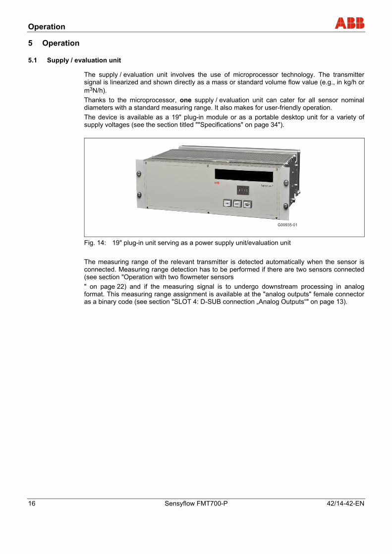
The device is available as a 19" plug-in module or as a portable desktop unit for a variety of supply voltages (see the section titled ""Specifications" on page 34").
Fig. 14: 19" plug-in unit serving as a power supply unit/evaluation unit
The measuring range of the relevant transmitter is detected automatically when the sensor is connected. Measuring range detection has to be performed if there are two sensors connected (see section "Operation with two flowmeter sensors
" on page 22) and if the measuring signal is to undergo downstream processing in analog format. This measuring range assignment is available at the "analog outputs" female connector as a binary code (see section "SLOT 4: D-SUB connection „Analog Outputs“" on page 13).
G00935-01

Operation
42/14-42-EN Sensyflow FMT700-P 17
5.2 Display unit (Display)
G00936
Fig. 15: Display of the supply / evaluation unit (lamp test during switch-on)
The largest display value supported by the six-digit digital display is 999999.
The units for the measured value indicated appear on the right next to the digital display. The default unit is kg/h. Other units are also supported.
"SENSOR 1" appears when transmitter 1 is selected.
"SENSOR 2" appears when transmitter 2 is selected (see section 5.5).
"TEMP 1" appears when the temperature of the fluid in transmitter 1 is requested.
"TEMP 2" appears when the temperature of the fluid in transmitter 2 is requested (see section 5.4).
"R.C. REMOTE-CTRL" appears when the device is in "Totalizer" mode (see section 6.1.2).
5.3 Options
5.3.1 Adjustable measuring rate
It is often useful to produce an average from the configurable number of individual measurements. You can set the required number of individual measurements using the selector switch on the front of the supply / evaluation unit.
A measuring cycle period (time for an individual measurement) lasts approximately 3 milliseconds. The average value calculated for the number of individual measurements configured is displayed and made available at the interfaces. In standard mode (i.e., when the device is switched on/before the set measuring rate is adopted), the device automatically generates a value from 1 individual measurement.
If the device generates an average value from fewer than 100 individual measurements, the set measuring rate is used for the analog outputs and the 12-bit parallel interface.
However, the digital display and the serial interface still contain measured values reflecting an average value for 100 individual measurements.
Proceed as follows to set a measuring rate:
1. Set the required measuring rate using the selector switch on the front of the supply / evaluation unit.
2. Press the "SAMPLE RATE" button to accept the set measuring rate. The selected measuring rate appears briefly in the display field as an acknowledgment signal. The measured value that appears after that is the first of the average values to be calculated from the newly configured number N.

Operation
18 Sensyflow FMT700-P 42/14-42-EN
IMPORTANT (NOTE)
Whenever the measuring system is switched on or after a reset, the device adopts a measuring rate of N = 1 as soon as the internal test routines have been completed.
Example:
The average mass flowrate needs to be determined using an interval of 3 seconds.
What measuring rate should be set?
3 s = 3,000 ms
N = 1 = 3 ms
Presetting counter setting
= T
= I
= N
Required interval
Duration of a single measurement
No. of individual measurements
10003
3000
I
TN
Thus, the measuring rate should be set to N = 1,000 on the switch.
This means that the four-digit switch can be used to produce an average value for the mass flowrate based on up to 9,999 individual measurements.
When a measuring rate of "0000" is selected, the measuring cycle period is just 1 millisecond (see section "Fast measuring rate" on page 18).
To summarize:
• If a low measuring rate is set, the average is produced from a small number of individual measurements and it is possible to measure and record dynamic processes.
• If a high measuring rate is set, the average is produced from a large number of individual measurements and undesirable fluctuations can be eliminated.
5.3.2 Fast measuring rate
This operating mode is for measuring very fast, dynamic processes. The measuring cycle period is 1 ms, i.e., an updated measured value is made available at the analog outputs and at the 12-bit parallel interface once every millisecond.
Proceed as follows to set this operating mode:
• Set the measuring rate to "0000" using the switch on the front of the supply / evaluation unit.
• Press the "SAMPLE RATE" button to accept this measuring rate. "_ _ _ _ _ _ " appears on the display along with "FAST MODE".
IMPORTANT (NOTE)
If you want the device to revert to the default setting (N = 1), you need to reset it (press RESET button) or restart it completely. As soon as the internal test routines have been completed (during which all the indicators light up), the measuring system starts taking measurements using the default measuring rate setting of N = 1 again.

Operation
42/14-42-EN Sensyflow FMT700-P 19
5.3.3 Analog outputs
The following 3 analog outputs are available as options:
0 ... 10 V 0 ... 20 mA 4 ... 20 mA
The previously set measuring rate (see section "Adjustable measuring rate" on page 17) is used for the analog interfaces.
Additional signal-processing units can be connected to the analog outputs, e.g.:
• A recorder
• An oscilloscope
• A transient recorder
• A process computer
• A controller
This makes it possible to visualize and record rapidly changing flowrates.
The Sensyflow FMT700-P measuring system has been specially developed for applications that call for a rapid response time where changes in flowrate are concerned. Fig. 16 illustrates the high speed of the measuring signal response when a throttle valve opens compared with the sluggish behavior associated with a orifice plate.
Sensyflow FMT700-P
G00937
1
2
0,1 s
Time →
Fig. 16: Dynamic measurement: Comparison of Sensyflow FMT700-P and orifice plate in terms of response time
1 Orifice plate 2 Position of throttle valve
Operation
20 Sensyflow FMT700-P 42/14-42-EN
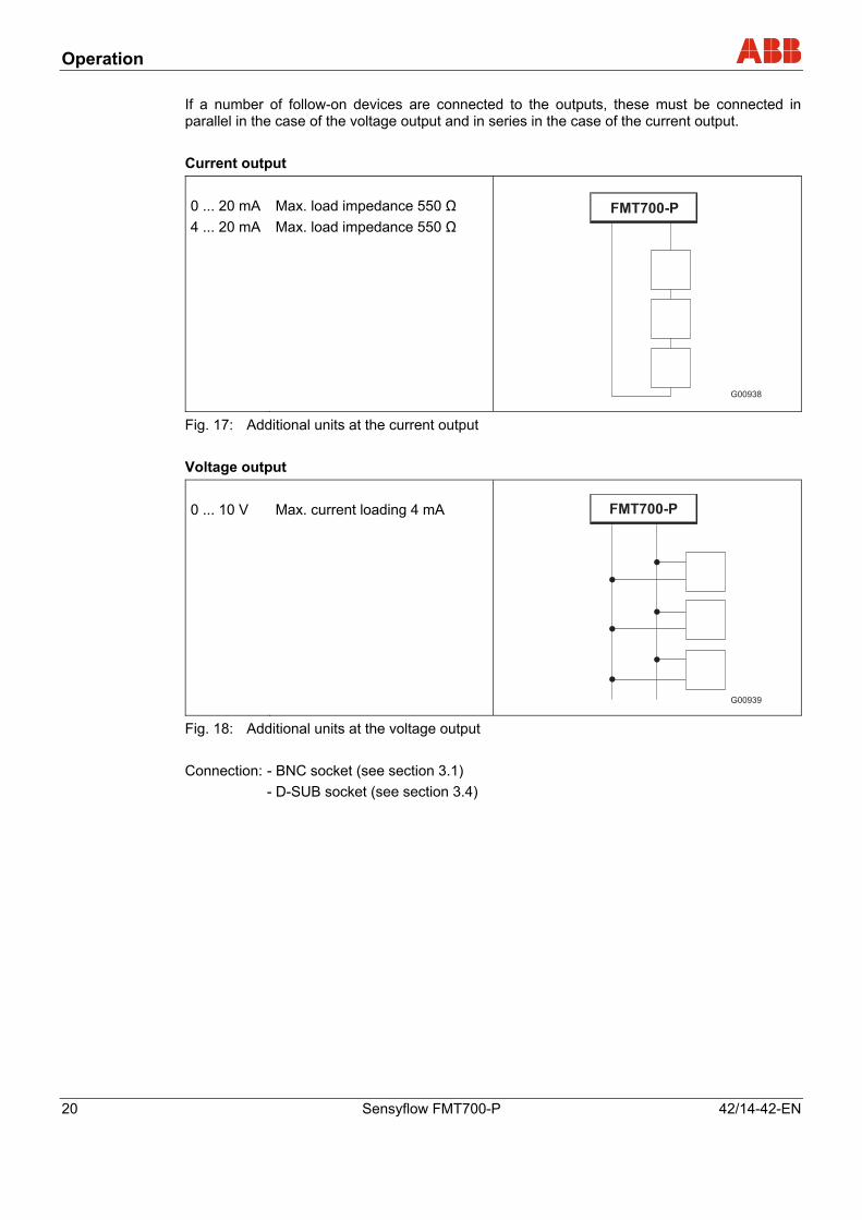
If a number of follow-on devices are connected to the outputs, these must be connected in parallel in the case of the voltage output and in series in the case of the current output.
Current output
0 ... 20 mA
4 ... 20 mA
Max. load impedance 550 Ω
Max. load impedance 550 Ω
G00938
FMT700-P
Fig. 17: Additional units at the current output
Voltage output
0 ... 10 V
Max. current loading 4 mA
G00939
FMT700-P
Fig. 18: Additional units at the voltage output
Connection: - BNC socket (see section 3.1)
- D-SUB socket (see section 3.4)

Operation
42/14-42-EN Sensyflow FMT700-P 21
5.4 Temperature measurement
Installing an additional measurement resistor (Pt100) in the flowmeter sensor makes it possible to measure the temperature of the air. With a nominal diameter of DN 25, the Pt100 is installed in the inlet section.
To display the temperature of the fluid, press the "TEMP" button. Press the button again if you want the unit to revert to its initial state (flow measurement).
Measuring principle
Using a transmitter, the Pt100's resistance signal is converted into a temperature-linear 4 ... 20 mA current signal while it is still inside the flowmeter sensor. It is then displayed as a temperature in °C. If you need the temperature signal to undergo downstream electrical processing, a jumper must be removed from inside the device (by the factory). In such cases, the electrical circuit outside the device has to be completed using a display unit or recorder (for example). The maximum permissible load is 120 Ω.
During temperature measurement, the corresponding flowrate signal is not made available at the interfaces.
Specifications for temperature measurement using Pt100
Response times in air at v = 1 m/s T50 = 3 s T90 = 10 s
Measuring range -20 ... 100 °C (-4 ... 212 °F)
Measurement uncertainty under ambient conditions ± 0.4 °C (32.72 °F)
G00940
8 8 8 8 8 8T
E
Pt 100
12
3
45
Fig. 19: Gas temperature measurement
1 18 V (internal) 2 Display 3 Jumper (internal)
4 Transmitter 5 Analog output 4 ... 20 mA
The temperature-linear 4 ... 20 mA signal is made available (once the jumper has been disconnected by the factory) at pins 11 and 24 (or 12 and 25 if operation involves the use of two flowmeter sensors) (see section 3.4).

Operation
22 Sensyflow FMT700-P 42/14-42-EN
5.5 Operation with two flowmeter sensors
Two flowmeter sensors with any nominal diameter can be connected to the supply / evaluation unit. Both flowmeter sensors (e.g., DN 25 and DN 150) are constantly available for measurements.
IMPORTANT (NOTE)
Only those measured values for the flowmeter sensor selected via the "SENSOR SELECT" button are shown on the "DISPLAY" and output as an optional digital and / or analog signal. The set measuring rate (see section "Adjustable measuring rate" on page 17) applies to both flowmeter sensors.
Selecting the required flowmeter sensor
• Press the "SENSOR SELECT" button until the required flowmeter sensor is selected.
• To determine which flowmeter sensor is active, refer to the display to see if it showing "SENSOR 1" or "SENSOR 2" and / or determine it on the basis of the coding at the 25-pin D-SUB-socket.
Communication
42/14-42-EN Sensyflow FMT700-P 23
Kommunikation
6 Communication
6.1 Digital interfaces
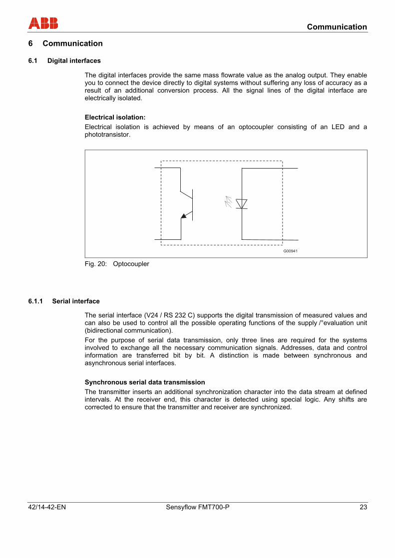
The digital interfaces provide the same mass flowrate value as the analog output. They enable you to connect the device directly to digital systems without suffering any loss of accuracy as a result of an additional conversion process. All the signal lines of the digital interface are electrically isolated.
Electrical isolation:
Electrical isolation is achieved by means of an optocoupler consisting of an LED and a phototransistor.
G00941
Fig. 20: Optocoupler
6.1.1 Serial interface
The serial interface (V24 / RS 232 C) supports the digital transmission of measured values and can also be used to control all the possible operating functions of the supply /°evaluation unit (bidirectional communication).
For the purpose of serial data transmission, only three lines are required for the systems involved to exchange all the necessary communication signals. Addresses, data and control information are transferred bit by bit. A distinction is made between synchronous and asynchronous serial interfaces.
Synchronous serial data transmission
The transmitter inserts an additional synchronization character into the data stream at defined intervals. At the receiver end, this character is detected using special logic. Any shifts are corrected to ensure that the transmitter and receiver are synchronized.
Communication
24 Sensyflow FMT700-P 42/14-42-EN
Asynchronous serial data transmission
The process whereby data is transmitted in small units of equal length without any additional clock information is known as asynchronous data communication without clock signals.
The transmitter and receiver must be clear about the transmission conditions involved, e.g.:
• Transmission speed (baud rate)
• Word length
• Number of start and stop bits (format)
• Bit assignment
• Signal voltage
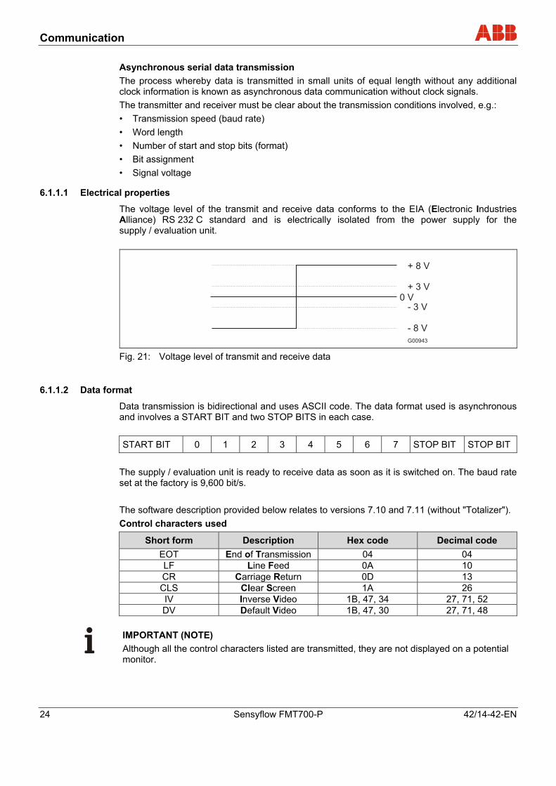
6.1.1.1 Electrical properties
The voltage level of the transmit and receive data conforms to the EIA (Electronic Industries Alliance) RS 232 C standard and is electrically isolated from the power supply for the supply / evaluation unit.
G00943
0 V
+ 8 V
- 3 V
- 8 V
+ 3 V
Fig. 21: Voltage level of transmit and receive data
6.1.1.2 Data format
Data transmission is bidirectional and uses ASCII code. The data format used is asynchronous and involves a START BIT and two STOP BITS in each case.
START BIT 0 1 2 3 4 5 6 7 STOP BIT STOP BIT
The supply / evaluation unit is ready to receive data as soon as it is switched on. The baud rate set at the factory is 9,600 bit/s.
The software description provided below relates to versions 7.10 and 7.11 (without "Totalizer").
Control characters used
Short form Description Hex code Decimal code
EOT End of Transmission 04 04 LF Line Feed 0A 10 CR Carriage Return 0D 13 CLS Clear Screen 1A 26 IV Inverse Video 1B, 47, 34 27, 71, 52 DV Default Video 1B, 47, 30 27, 71, 48
IMPORTANT (NOTE)
Although all the control characters listed are transmitted, they are not displayed on a potential monitor.
Communication
42/14-42-EN Sensyflow FMT700-P 25
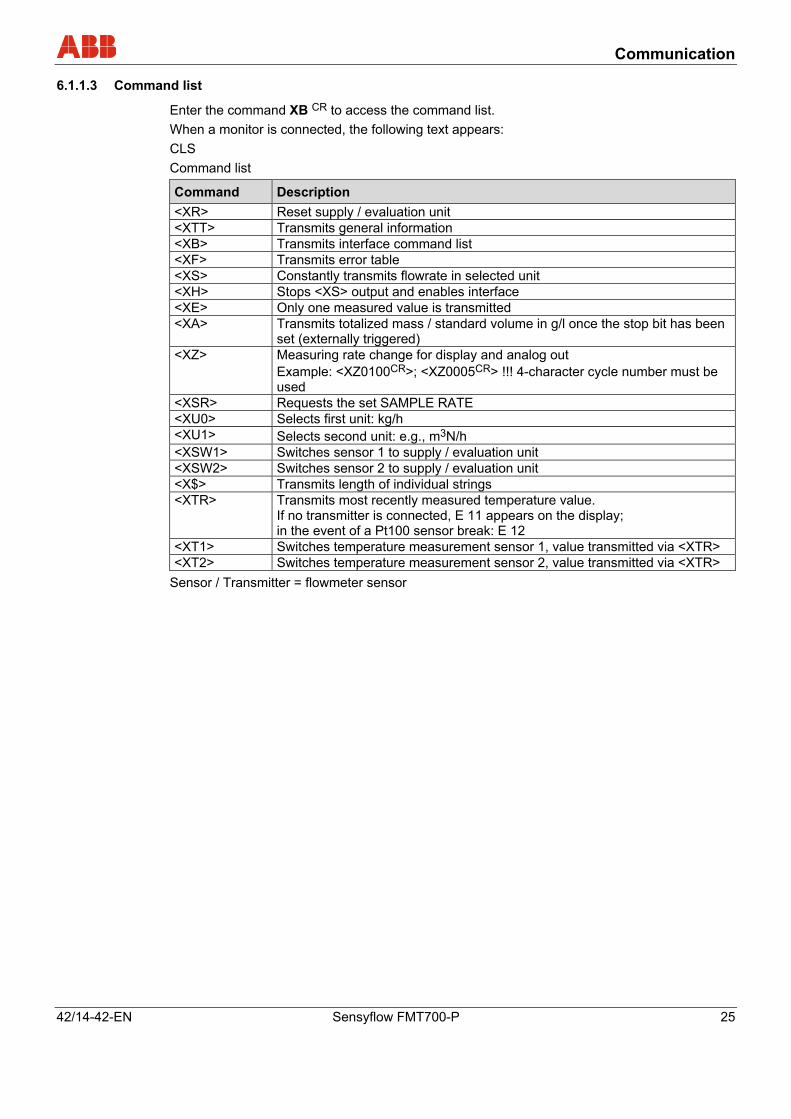
6.1.1.3 Command list
Enter the command XB CR to access the command list.
When a monitor is connected, the following text appears:
CLS
Command list
Command Description
<XR> Reset supply / evaluation unit <XTT> Transmits general information <XB> Transmits interface command list <XF> Transmits error table <XS> Constantly transmits flowrate in selected unit <XH> Stops <XS> output and enables interface <XE> Only one measured value is transmitted <XA> Transmits totalized mass / standard volume in g/l once the stop bit has been
set (externally triggered) <XZ> Measuring rate change for display and analog out
Example: <XZ0100CR>; <XZ0005CR> !!! 4-character cycle number must be used
<XSR> Requests the set SAMPLE RATE <XU0> Selects first unit: kg/h <XU1> Selects second unit: e.g., m3N/h <XSW1> Switches sensor 1 to supply / evaluation unit <XSW2> Switches sensor 2 to supply / evaluation unit <X$> Transmits length of individual strings <XTR> Transmits most recently measured temperature value.
If no transmitter is connected, E 11 appears on the display; in the event of a Pt100 sensor break: E 12
<XT1> Switches temperature measurement sensor 1, value transmitted via <XTR> <XT2> Switches temperature measurement sensor 2, value transmitted via <XTR>
Sensor / Transmitter = flowmeter sensor
Communication
26 Sensyflow FMT700-P 42/14-42-EN
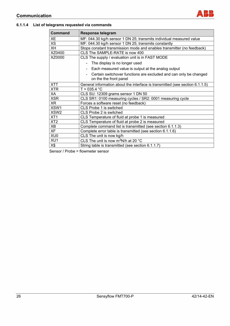
6.1.1.4 List of telegrams requested via commands
Command Response telegram
XE MF: 044.30 kg/h sensor 1 DN 25; transmits individual measured value XS MF: 044.30 kg/h sensor 1 DN 25; transmits constantly XH Stops constant transmission mode and enables transmitter (no feedback) XZ0400 CLS The SAMPLE-RATE is now 400 XZ0000 CLS The supply / evaluation unit is in FAST MODE
- The display is no longer used
- Each measured value is output at the analog output
- Certain switchover functions are excluded and can only be changed on the the front panel
XTT General information about the interface is transmitted (see section 6.1.1.5) XTR T = 035.4 °C XA CLS SU: 12309 grams sensor 1 DN 50 XSR CLS SR1: 0100 measuring cycles / SR2: 0001 measuring cycle XR Forces a software reset (no feedback) XSW1 CLS Probe 1 is switched XSW2 CLS Probe 2 is switched XT1 CLS Temperature of fluid at probe 1 is measured XT2 CLS Temperature of fluid at probe 2 is measured XB Complete command list is transmitted (see section 6.1.1.3) XF Complete error table is transmitted (see section 6.1.1.6) XU0 CLS The unit is now kg/h XU1 CLS The unit is now m3N/h at 20 °C X$ String table is transmitted (see section 6.1.1.7)
Sensor / Probe = flowmeter sensor

Communication
42/14-42-EN Sensyflow FMT700-P 27
6.1.1.5 General information
Enter the command XTT CR to access general information about the interface. When a monitor is connected, the following text appears:
CLS, IV General information Vers. X.XX Progr. Sensyflow FMT700-P
Digital interfaces 15-bit output + data ready
12-bit digital out / optically decoupled Serial interface RS 232 / V 24 Serial interface command list <XB> Analog interface 0 ... 10 V or 0 ... 20 mA / 4 ... 20 mA Digital coding of flowmeter sensor size
E.g., DN 25 Sensor 1 1100 1100
Measuring rate for display and analog output changed via BCD switch
Measuring rate for display 0100 ... 9999 measuring cycles Measuring rate for analog out 0001 ... 9999 measuring cycles Fast mode Display not used; each measured value is sent to the
analog output Temperature option Measuring range -20 ... 100 °C 2-probe operation Switchover between 2 sensors
Sensor / Probe = flowmeter sensor
6.1.1.6 Error table
Enter the command XF CR to access the error table. When a monitor is connected, the following text appears:
CLS
"Sensyflow FMT700-P" error table
Error Description
999999 Measured value ≥ measuring range (normal operation) E02 No probe connected E03 Sum register overflow E04 A measured value > probe's URL E11 No transmitter connected E12 Pt100 sensor break E13 ... E14 ... E15 ... E16 ... E17 ... E18 ... E19 ... E20 ...
Sensor / Probe / Transmitter = flowmeter sensor
URL = Upper range limit

Communication
28 Sensyflow FMT700-P 42/14-42-EN
6.1.1.7 Length of transmitted strings
Enter the command X$ to access the string table. When a monitor is connected, the following text appears:
CLS Length of transmitted strings:
String Length in hexadecimal format
Length in decimal format
<XTT> 03AD 941 <XB> 0421 1057 <XF> 02C6 710 <XS> 0020 32 <XH> Resets interface <XE> 0020 32 <XA> 0020 32 <XZ> 0025 37 <XSR> 002A 42 <XTR> 0012 18 <XU0> 0022 34 <XU1> 002F 47 <XSW1> 001B 27 <XSW2> 001B 27 <X$> 03AD 941 <XT1> 0034 52 <XT2> 0034 52
Comment
1. <XS> transmits constantly
2. Each command must end with CR
IMPORTANT (NOTE)
• 4 characters must always be entered when setting the measuring rate (see section "Command list" on page 25), e.g., for a SAMPLE RATE of 50, the command XZ _ _ 50 CR must be entered.
• During constant transmission mode, no other operating mode can be set via the serial interface. The RS 232 C serial interface is blocked and can only be enabled using XH CR.
• When the meter is being operated, there is no conflict between the serial interface and the keypad on the front panel. No priority circuit is required.
• During FAST MODE, all the values and tables stored in the memory (texts, temperatures, lists, etc.) can be accessed via the serial interface.
• While this is happening (processing time), FAST MODE is interrupted (analog value is retained). Once processing is complete, FAST MODE is resumed.
• You can exit this operating mode again using the commands CR or XZ CR.

Communication
42/14-42-EN Sensyflow FMT700-P 29
6.1.2 Totalizer (integrator function)
This operating mode is used to determine the air mass that flows through the flowmeter sensor during a defined measurement period that is externally triggered. The result is displayed digitally and can be read out via the serial interface or via a 15-bit parallel interface (binary-coded, electrically isolated) (see section "Electrical connections" on page 11).
The unit used for the totalized value is either grams or normal liters.
The measurement period (Tm) is defined by the external START / STOP signal at the REMOTE CTRL input.
The START signal (falling edge at REMOTE CTRL input) triggers switchover to the special operating mode and simultaneously initiates the measuring process.
The STOP signal (marking the end of the measuring process) is triggered by a rising edge at the REMOTE CTRL input (see section "SLOT 3: D-SUB connection „Totalizer“" on page 12).
Uexternal 5 ... 24 V
G00944
Tm
0 V
Fig. 22: Voltage states at REMOTE CTRL input
While this special mode is active, the REMOTE CTRL indicator (RC) to the left of the 6-digit LED display lights up.
The 6-digit LED display is switched off and the measuring rate setting is deactivated. The current flowrate remains constantly available at the analog output during this period (measuring rate N = 1 = 1 ms.; see section "Adjustable measuring rate" on page 17).
IMPORTANT (NOTE)
If one or more individual measured values exceeds the calibrated measuring range while the special mode is active, all DATA BITS are set once the STOP signal is detected, as is the DATA READY BIT. When the device switches back to normal operation, 999999 initially appears on the display before normal operation is resumed.

Communication
30 Sensyflow FMT700-P 42/14-42-EN
6.1.2.1 How the totalized value is represented
The value can be represented in 3 ways:
1. Shown on display "1." is generally combined with "2." or "3." The display period is determined by 2 factors:
- A fixed "readout time", approx. 5 seconds
- The set measuring rate (see section 6.2.1)
The result is displayed in grams (g) or normal liters (lN). 2. 15-bit parallel interface Following the STOP signal, the mass flowrate value ("m") is
made available at the digital output for approx. 15 seconds in the form of a digital 15-bit binary signal along with the DATA READY BIT.
For details of pin assignment, see section 3.3. The measured value ("m") is output in grams (g) or normal liters (lN).
After approx. 5 seconds, the device automatically switches over to the normal operating mode.
3. Serial interface As with the 15-bit interface, the START / STOP signal is implemented using pins 23 and 24 of the 25-pin D-SUB socket (see section 3.3). Once the measuring process is complete, the totalized value is stored. Use the command XA CR to retrieve this value.

Communication
42/14-42-EN Sensyflow FMT700-P 31
6.1.2.2 Specifications for the special "Totalizer" mode
All signal lines of the digital inputs and outputs are optically decoupled.
IMPORTANT (NOTE)
The outputs are connected as OPEN COLLECTORS (see section 3.3).
Permissible measurement period TM 10 s ≤ TM ≤ 115 s
Error due to measurement interval 0.05 % with TM = 100 s
0.15% with TM = 10 s
Measurement uncertainty when determining air mass
± 2 %
Auxiliary voltage required (UEXTERNAL) 5 ... 24 V DC (I = 20 mA at 20 V)
Totalized measured value M M ≤ 32,767 g ((215 ... 1) g)
The max. permissible measurement period depends on the mass flowrate.
Mea
sure
men
t per
iod
[s]
G00945
120110
100
90
80
70
60
50
40
30
20
10
1000 2000 3000 4000
Flowrate [kg/h]
Fig. 23: Measuring range of totalizer

Measuring setup and installation
32 Sensyflow FMT700-P 42/14-42-EN
7 Measuring setup and installation
The flowmeter sensor has been designed for maximum measuring accuracy while at the same time being easy to use. Nevertheless, certain boundary conditions must be observed to ensure the best possible absolute accuracy and reproducibility.
Maximum measuring accuracy is achieved by calibrating the measuring section together with the flowmeter sensor (achievable accuracy: m = ± 1 % from measured value).
By identifying the correct honeycomb/sieve combination on the basis of calculations as well as a process of trial and error, you can steady the flow with a view to minimizing the effect of inlet conditions on the probe characteristic.
The flowmeter sensors are calibrated in the horizontal mounting position. The signal is only slightly dependent on the mounting position.
Optimum measuring section setup:
Air filter
FMT700-P
G00981
Undisturbed inlet section
10 x D Undisturbed outlet
section 5 x D
Fig. 24: Preferred setup for a measuring section involving the Sensyflow FMT700-P
IMPORTANT (NOTE)
• The flow direction of the measuring fluid must match the arrow on the probe.
• Particles and fibers can impair measuring accuracy. We therefore recommend that you use an air filter from our range of accessories for filtering purposes (see section 9.4). The use of suitable air filters is essential to ensuring desirable inflow characteristics and high levels of operational reliability during continuous operation, even under difficult operating conditions.
• Backflow and pulsation problems can be reduced or fully compensated by installing a suitable surge drum upstream.
• If the optimum measuring setup is not possible due to space restrictions (e.g., trial run), the flowmeter sensor can also be installed using straightforward equipment (rubber sleeve). Even then, the device will still be able to deliver good measurement results.
• The flowmeter sensor and all original accessories have been designed in such a way that they can be very easily adapted using tapered flange couplings.
• Do not attach the flowmeter sensor directly to systems that are subject to high levels of vibration. We recommend that you adapt them by using a rubber sleeve to isolate the vibrations. The honeycomb must be protected from mechanical damage.
• To ensure fault-free signal processing, only the original probe cable should be used.
• The measuring system must undergo regular control calibrations on the manufacturer's test bench. The intervals involved will depend on the operating time and the nature of the load; however, we generally recommend calibration intervals of 12 ... 24 months.

Measuring setup and installation
42/14-42-EN Sensyflow FMT700-P 33
Adaptation options
• DN 25, DN 50, DN 80, DN 100: Tapered flanges are centrically compressed using a tension clip (vacuum clamping technology).
• DN 150, DN 200: Tapered flanges are centrically compressed using a tension chain.
Specifications
34 Sensyflow FMT700-P 42/14-42-EN
8 Specifications Change from one to two columns
Measuring principle Thermal: hot film anemometer
Input Measured variable Air
Measuring ranges (standard) Nominal diameter kg/h DN 25 0 (1) ... 60 DN 50 0 (10) ... 400 DN 80 0 (20) ... 720 DN 100 0 (40) ... 1200 DN 150 0 (80) ... 2400 DN 200 0 (200) ... 4000
Output Output signals Analog 0 ... 10 V (< 1 mA) 0 ... 20 mA (load < 500 ) 4 ... 20 mA (load < 500 )
Digital output serial V24 / RS 232 C, electrically isolated
Characteristic values Measuring error Measuring error (including hysteresis and non-linearity) < ± 1 % of measured value
Reproducibility < ± 0.25 % of measured value
Influences Temperature effect < 0.03 % / K of measured value
Pressure effect ≤ 0.2 % / 100 kPa (/bar) of measured value
Response time T63 12 ms
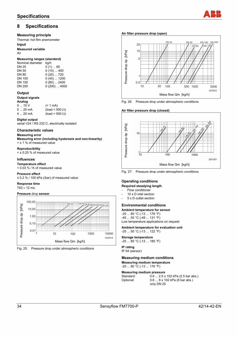
Pressure drop sensor
Pre
ssur
e dr
op d
p [
hPa]
G00918
DN 25 DN 50 DN 80 DN100 DN150DN 200
0,01
0,10
1,00
10,00
100,00
1 100 1000 1000010
Mass flow Qm [kg/h]
Fig. 25: Pressure drop under atmospheric conditions
Air filter pressure drop (open)
Pre
ssur
e dr
op d
p [
hPa]
G00922
DN 25 DN 50 DN 200DN 10020
10
5
1
0.5
10 50 100 500 1000 5000
DN 150DN 80
Mass flow Qm [kg/h]
Fig. 26: Pressure drop under atmospheric conditions
Air filter pressure drop (closed)
Pre
ssur
e dr
op d
p [
hPa]
Mass flow Qm [kg/h]
Fig. 27: Pressure drop under atmospheric conditions
Operating conditions Required steadying length - Flow conditioner - 10 x D inlet section - 5 x D outlet section
Environmental conditions Ambient temperature for sensor -25 ... 80 °C (-13 ... 176 °F) -45 ... 55 °C (-49 ... 131 °F) Low temperature applications on request
Ambient temperature for evaluation unit -25 ... 50 °C (-13 ... 122 °F)
Storage temperature -25 ... 85 °C (-13 ... 185 °F)
IP rating IP 54 (sensor)
Measuring medium conditions Measuring medium temperature -25 ... 80 °C (-13 ... 176 °F)
Measuring medium pressure Standard: 0.6 ... 2.5 x 10² kPa (2.5 bar abs.) Optional: 0.6 ... 8 x 10² kPa (8 bar abs.) only DN 25
G01351
1
10
10 100 1000
DN
25
DN
150
DN
80D
N 5
0 DN
200
DN
100
Specifications
42/14-42-EN Sensyflow FMT700-P 35
Constructional design Weight Sensor (meter tube) depending on nominal diameter, see ordering information Evaluation unit 19" plug-in unit 7.0 kg (15.4 lb) 1/2 19" desktop housing 7.3 kg (16.1 lb)
Material Sensor: aluminum, black anodized Steadying lengths: aluminum, black anodized or stainless steel, from DN 150
Process connection Quick-clamping pipe flange, aluminum with quick-clamping chains/quick-clamping rings
Electrical connection Sensor: via sensor connection cable to power supply unit/evaluation unit
Power supply Power supply unit/evaluation unit, voltage 230 V AC 115 V AC
Power consumption evaluation unit 38 W
Power consumption sensor 10 W
Current drain sensor < 600 mA
Change from one to two columns
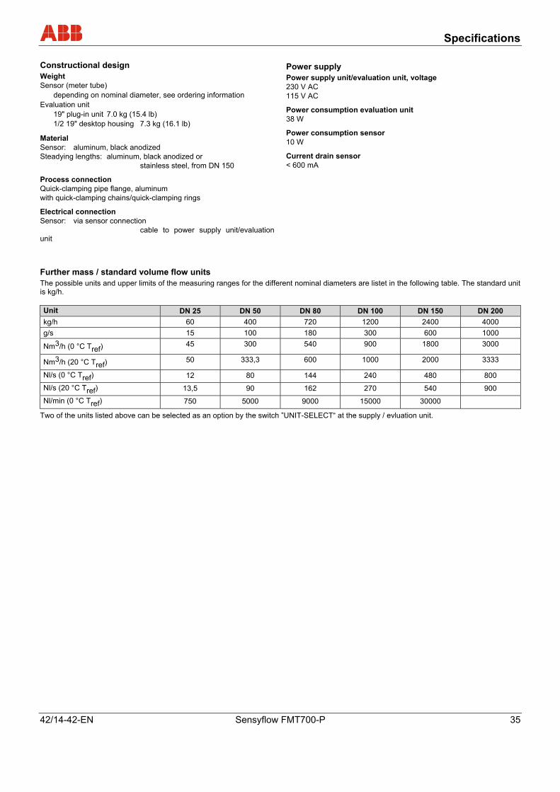
Further mass / standard volume flow units The possible units and upper limits of the measuring ranges for the different nominal diameters are listet in the following table. The standard unit is kg/h. Unit DN 25 DN 50 DN 80 DN 100 DN 150 DN 200
kg/h 60 400 720 1200 2400 4000
g/s 15 100 180 300 600 1000
Nm3/h (0 °C Tref) 45 300 540 900 1800 3000
Nm3/h (20 °C Tref) 50 333,3 600 1000 2000 3333
Nl/s (0 °C Tref) 12 80 144 240 480 800
Nl/s (20 °C Tref) 13,5 90 162 270 540 900
Nl/min (0 °C Tref) 750 5000 9000 15000 30000
Two of the units listed above can be selected as an option by the switch ”UNIT-SELECT“ at the supply / evluation unit.

Dimensions
36 Sensyflow FMT700-P 42/14-42-EN
9 Dimensions
9.1 Flowmeter sensor Sensyflow FMT700-P, DN 25
G00903
DN
25
KF
M6
170 (6.69)
125 (4.92)22 5. 22 5.
95 (3.74) 1515
Ø(0
.94)
24
(0.89) (0.89)
(0.59) (0.59)
73 (2.87)
52 (2.05) 21 (0.83)
60
5,(2
.38)
31
5.
12
(0.4
7)9
2(3
.62)
6
(1.2
4)
(0.24)
Fig. 28: Dimensions in mm (inch
Dimensions
42/14-42-EN Sensyflow FMT700-P 37
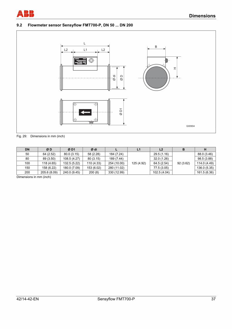
9.2 Flowmeter sensor Sensyflow FMT700-P, DN 50 ... DN 200
L
L2 L1 L2
Ød
i
ØD
ØD
1
B
H
G00904
Fig. 29: Dimensions in mm (inch)
DN Ø D Ø D1 Ø di L L1 L2 B H
50 64 (2.52) 80.0 (3.15) 58 (2.28) 184 (7.24)
125 (4.92)
29.5 (1.16)
92 (3.62)
88.0 (3.46)
80 89 (3.50) 108.5 (4.27) 80 (3.15) 189 (7.44) 32.0 (1.26) 98.5 (3.88)
100 118 (4.65) 132.5 (5.22) 110 (4.33) 254 (10.00) 64.5 (2.54) 114.0 (4.49)
150 158 (6.22) 180.0 (7.09) 153 (6.02) 280 (11.02) 77.5 (3.05) 136.0 (5.35)
200 205.6 (8.09) 240.0 (9.45) 200 (8) 330 (12.99) 102.5 (4.04) 161.5 (6.36)
Dimensions in mm (inch)

Dimensions
38 Sensyflow FMT700-P 42/14-42-EN
9.3 Supply / evaluation unit
19” plug-in version 1/2 19” desktop housing
G00905
X
h H
L
H
T
t
I
L
1
2
Fig. 30
1 Required cutout for 19” unit: 450 x 131 mm (17.72 x 5.16 inch)
2 For wiring
Unit Dimensions L I H h T t X
1/2 19“ desktop housing 310 (12.2) - 140 (5.5) - - - -
19“ plug-in version 483 (19.0) 462 (18.2) 132 (5.2) 58 (2.3) 425 (16.7) 325 (12.8) M6
Dimensions in mm (inch)
9.4 Accessories Change from one to two columns
In order to simplify the installation of our measuring system for the user, we recommend to apply approved components from our extensive accessories program. Tubes of different lengths as inlet section or outlet section are available which can be combined with an air filter.
We recommend an undisturbed inlet section of 10 x D, a outlet section of 5 x D and the application of an air filter (this combination represents the calibration set of the manufacturer). D = tube diameter.
Change from one to two columns
G00981
Fig. 31: Standard measuring section: measuring section 3

Dimensions
42/14-42-EN Sensyflow FMT700-P 39
DN 25 components
KF = ISO KF flange (ISO small flange)
① ② ③ ⑥ Air filter (open)
with flange 10 x D inlet section with flanges (on both sides)
5 x D outlet section with flanges (on both sides)
Hose adapter with flange (on one side)
⑦ ④ ⑤
Flow conditioner with flange
10 x D inlet section with flange (on one side)
5 x D outlet section with flange (on one side)
Standard measuring section Measuring section 3
(including flow conditioner, closed filter) Alternative measuring section 1 (represented by the dashed line, including open filter, filter cartridge only) Including the required flanges and clamping rings/clamping chains
Fig. 32: Dimensions in mm (inch)
DN Ø D Ø D2 Ø D3 Ø D4 Ø D6 Ø D7 Ø Di
25 32 (1.26) 26,1 (1.03) 30 (1.18) 27 (1.06) ca. 150 (5.91) 78 (3.07) 24 (0.94)
Dimensions in mm (inch)

Dimensions
40 Sensyflow FMT700-P 42/14-42-EN
DN 25 components
KF = ISO KF flange (ISO small flange)
⑫ ⑬ ⑪ ⑭ O-ring Clamping ring
FL-special Inner centering ring
Clamping ring FL-Optimal AS
⑥ ⑪ / ⑫ ⑥
Sectional detail pipe connection (without clamping ring)
Individual planning
Fig. 33: Dimensions in mm (inch)

Dimensions
42/14-42-EN Sensyflow FMT700-P 41
Modules DN 50 ... DN 100
KOF = Tapered flange (with recessed face and groove for O-ring)
ZWF = Wafer type (with raised face) ① ② ③ ⑥ Air filter (open)
with flange 10 x D inlet section with flanges (on both sides)
5 x D outlet section with flanges (on both sides)
Hose adapter with flange (on one side)
⑦ ④ ⑤
Flow conditioner with flange
10 x D inlet section with flange (on one side)
5 x D outlet section with flange (on one side)
Standard measuring section Measuring section 3
(including flow conditioner, closed filter) Alternative measuring section 1 (represented by the dashed line, including open filter, filter cartridge only) Including the required flanges and clamping rings/clamping chains
Fig. 34: Dimensions in mm (inch)
DN L1 L2 L3 L4 L5 L6 L7 L8 L9
50 Approx. 356 (14.02) 506 (19.92) 256 (10.08) 50 (1.97) Approx. 660 (25.98) 504 (19.84) 254 (10.00) Approx. 1600 (62.99) 184 (7.24)
80 Approx. 401 (15.79) 806 (31.73) 406 (15.98) 80 (3.15) Approx. 740 (29.13) 804 (31.65) 404 (15.91) Approx. 2140 (84.25) 189 (7.44)
100 Approx. 526 (20.71) 1006 (39.61) 506 (19.92) 100 (3.94) Approx. 840 (33.07) 1004 (39.53) 504 (19.84) Approx. 2610 (102.76) 254 (10.00)
DN Ø D Ø D2 Ø D3 Ø D4 Ø D5 Ø D6 Ø D7 Ø Di
50 66 (2.60) 64 (2.52) 70 (2.76) 60 (2.36) Approx. 150 (5.91) Approx. 200 (7.87) 78 (3.07) 58 (2.28)
80 91 (3.58) 89 (3.50) 95 (3.74) 85 (3.35) Approx. 200 (7.87) Approx. 250 (9.84) 98 (3.86) 80 (3.15)
100 119 (4.69) 118 (4.65) 122 (4.80) 114 (4.49) Approx. 240 (9.45) Approx. 300 (11.81) 148 (5.83) 110 (4.33)
Dimensions in mm (inch)

Dimensions
42 Sensyflow FMT700-P 42/14-42-EN
Modules DN 50 ... DN 100
KOF = Tapered flange (with recessed face and groove for O-ring)
ZWF = Wafer type (with raised face)
⑬ ⑩ ⑫ ⑪ Clamping ring Wafer type O-ring Tapered flange
⑩ ⑫ ⑪
Sectional detail pipe connection (without clamping ring)
Individual planning
Fig. 35: Dimensions in mm (inch)
DN L1 L2 L9 Ø D2 Ø Di
50 102 (4.02) 72 (2.83) 184 (7.24) 64 (2.52) 58 (2.28)
80 145 (5.71) 114 (4.49) 189 (7.44) 89 (3.50) 80 (3.15)
100 158 (6.22) 127 (5.00) 254 (10.00) 118 (4.65) 110 (4.33)
Dimensions in mm (inch)

Dimensions
42/14-42-EN Sensyflow FMT700-P 43
Modules DN 150 ... DN 200
KOF = Tapered flange (with raised face and groove for O-ring)
ZWF = Wafer type (with recessed face) ① ② ③ ⑥ Air filter (open)
with flange 10 x D inlet section with flanges (on both sides)
5 x D outlet section with flanges (on both sides)
Hose adapter with flange (on one side)
⑦ ④ ⑤
Flow conditioner with flange
10 x D inlet section with flange (on one side)
5 x D outlet section with flange (on one side)
Standard measuring section Measuring section 3
(including flow conditioner, closed filter) Alternative measuring section 1 (represented by the dashed line, including open filter, filter cartridge only) Including the required flanges and clamping rings/clamping chains
Fig. 36: Dimensions in mm (inch)
DN L1 L2 L3 L4 L5 L6 L7 L8 L9
150 Approx. 513 (20.20) 1518 (59.76) 768 (30.24) 159 (6.26) Approx. 900 (35.43) 1509 (59.41) 759 (29.88) Approx. 3460 (136.22) 280 (11.02)
200 Approx. 513 (20.20) 2018 (79.49) 1018 (40.08) 159 (6.26) Approx. 850 (33.46) 2009 (79.09) 1018 (40.08) Approx. 4220 (166.14) 330 (12.99)
DN Ø D Ø D2 Ø D4 Ø D5 Ø D6 Ø D7 Ø Di
150 151 (5.94) 158 (6.22) 153 (6.02) Approx. 300 (11.81) Approx. 350 (13.78) 198 (7.80) 149 (5.87)
200 201.5 (7.93) 205 (8.07) 204 (8.03) Approx. 300 (11.81) Approx. 350 (13.78) 248 (9.76) 199 (7.83)
Dimensions in mm (inch)
Dimensions
44 Sensyflow FMT700-P 42/14-42-EN
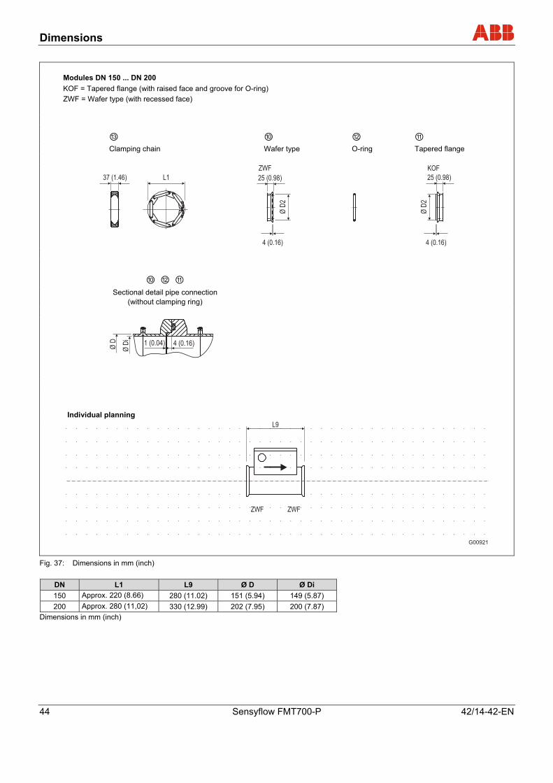
Modules DN 150 ... DN 200
KOF = Tapered flange (with raised face and groove for O-ring)
ZWF = Wafer type (with recessed face)
⑬ ⑩ ⑫ ⑪ Clamping chain Wafer type O-ring Tapered flange
⑩ ⑫ ⑪
Sectional detail pipe connection (without clamping ring)
Individual planning
Fig. 37: Dimensions in mm (inch)
DN L1 L9 Ø D Ø Di
150 Approx. 220 (8.66) 280 (11.02) 151 (5.94) 149 (5.87)
200 Approx. 280 (11,02) 330 (12.99) 202 (7.95) 200 (7.87)
Dimensions in mm (inch)
ZWF KOF
ØD
2
4 (0.16)
ØD
2
4 (0.16)
37 (1.46) L1 25 (0.98) 25 (0.98)
ØD
i
1 (0.04) 4 (0.16)
ØD
G00921
ZWF
L9
ZWF
Appendix
42/14-42-EN Sensyflow FMT700-P 45
10 Appendix
10.1 Decommissioning and packaging
Packaging the device ready for transport or return to the manufacturer
If the original packaging material is no longer available, wrap the device in bubble wrap or corrugated cardboard and place it in a box of sufficient size lined with a shock-absorbing material (e.g., foam rubber). The thickness of the padding should be appropriate for the device weight and type of shipment. The box must be handled with care and labeled accordingly.
For overseas shipment, always add a desiccant (e.g., silica gel) and hermetically seal the device plus desiccant in a layer of polythene that is 0.2 mm thick. Use an amount of desiccant that is appropriate for the packing volume and the expected transport time (at least sufficient for 3 months). You should also line the box with a layer of union paper.
All devices returned to the manufacturer must be accompanied by a completed and signed decontamination certificate (see Appendix). Without this, ABB will not be able to process the return.
10.2 Approvals and certifications
IMPORTANT (NOTE)
All documentation, declarations of conformity and certificates are available in ABB's download area.
www.abb.com/flow

Appendix
46 Sensyflow FMT700-P 42/14-42-EN
10.3 Return form
Statement on the contamination of devices and components Repair and/or maintenance work will only be performed on devices and components if a statement form has been completed and submitted. Otherwise, the device/component returned may be rejected. This statement form may only be completed and signed by authorized specialist personnel employed by the operator.
Customer details:
Company:
Address:
Contact person: Telephone:
Fax: Email:
Device details:
Type: Serial no.:
Reason for the return/description of the defect:
Was this device used in conjunction with substances which pose a threat or risk to health?
Yes No
If yes, which type of contamination (please place an X next to the applicable items)?
Biological Corrosive/irritating Combustible (slightly/extremely combustible)
Toxic Explosive Other Toxic substances
Radioactive
Which substances have come into contact with the device?
1.
2.
3.
We hereby state that the devices/components shipped have been cleaned and are free from any dangerous or poisonous substances.
Town/city, date Signature and company stamp

Notes
42/14-42-EN Sensyflow FMT700-P 47
Notes

ABB has Sales & Customer Support expertise in over 100 countries worldwide. www.abb.com/flow
The Company’s policy is one of continuous product improvement and the right is reserved to modify the
information contained herein without notice.
Printed in the Fed. Rep. of Germany (07.2017)
© ABB 2017
42/1
4-42
-EN
R
ev.
H
3KXF421006R4201
ABB Limited Measurement & Analytics Howard Road, St. Neots Cambridgeshire, PE19 8EU UK Tel: +44 (0) 870 600 6122 Fax: +44 (0)1480 213 339 Mail: [email protected]
ABB Inc. Measurement & Analytics 125 E. County Line Road Warminster, PA 18974 USA Tel: +1 215 674 6000 Fax: +1 215 674 7183
ABB Automation Products GmbH Measurement & Analytics Dransfelder Str. 2 37079 Goettingen Germany Tel: +49 551 905-0 Fax: +49 551 905-777 Mail: [email protected]


