75425 CENCO Ballistic Pendulum Page Operating Instructions: 75425 CENCO Ballistic Pendulum PRODUCT CONTENTS Quantity Description Rigid arm pendulum with support rod Brass ball with drilled hole Spring with gun release mechanism Metal Base Curved rack OTHER SUGGESTED MATERIALS Metric ruler Tape measure Wax pencil Spirit level, bubble level Sheet of carbon paper Table clamp Cardboard box for catching the ball Probeware a. Photogate system ASSEMBLY OF APPARATUS – Refer to Figure on next page . First, vertically insert the support rod M into the hole in the base N. Make sure that the flat area of the rod faces out towards the set screw hole on the side of the base. 2. Straighten the support rod so that its overhanging yoke (which supports the pendulum) is aligned perpendicular to the compressed spring. 3. Set the provided washer on the rod screw, and tightly fasten the underside of the rod into the base using an Allen wrench (see Fig- ure 2).
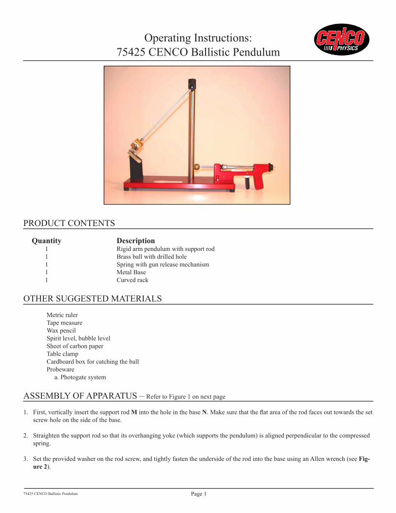
PrOduCt CONtENts Quantity Description � rigid arm pendulum with support rod � Brass ball with drilled hole � spring with gun release mechanism � Metal Base � Curved rack
OthEr suggEstEd MatErIals
Metric rulertape measureWax pencilspirit level, bubble levelsheet of carbon papertable clampCardboard box for catching the ballProbeware a. Photogate system
assEMBly Of aPParatus – refer to figure � on next page
�. first, vertically insert the support rod M into the hole in the base N. Make sure that the flat area of the rod faces out towards the set screw hole on the side of the base.
2. straighten the support rod so that its overhanging yoke (which supports the pendulum) is aligned perpendicular to the compressed spring.
3. set the provided washer on the rod screw, and tightly fasten the underside of the rod into the base using an allen wrench (see Fig-ure2).
75425 CENCO Ballistic Pendulum Page 2
4. Place the small, cylindrical set screw provided into the hole it fits in on the back side of the base. It is important that the flat, silver side of the set screw goes in first, allowing it to press up against the side of the rod. Use an Allen wrench to secure the set screw into place.
5. Place the brass ball B on the end of the rod H, sliding the appropriately sized hole in the ball onto the rod.
6. Insert the cone-pivot bearings of the light rod K into the inset at the top of the support rod. Make sure that the side of the cylindri-cal bob C with a larger hole is facing the brass ball B on the compressed spring gun.
7. use the shouldered screw L to adjust the positioning of the light rod K so that the pendulum, when pivoted on its axis, aligns with the brass ball resting on the end of the horizontal rod H. In other words, when the pendulum is swung, the cylindrical bob C should smoothly swing into and contain the brass ball. the shouldered screw should be tightened to the point where the pendulum can swing with little friction with the cone-pivot bearings (don’t tighten the screw too much).
Figure 1: Labeled Image of the CENCO Ballistic Pendulum Apparatus
Figure 2: Close-Up of Smaller Assembly Parts
t
PhB
M
l
K
C
P
r
N
rod screwallan Wrench
set screwWasher
75425 CENCO Ballistic Pendulum Page 3
dEsCrIPtION Of usE/BaCKgrOuNd INfOrMatION
the Cenco Ballistic Pendulum (75425) is designed to study the laws of momentum conservation and reinforce elements of projectile motion. the apparatus has a pendulum bob that will catch and hold a projectile shot from its gun, and it also has a ratchet system (with a positioning scale) that measures the height to which the bob rises after it catches the ball. students can equate the momentum of the ball immediately before impact to the momentum of the ball and bob together an instant after impact. students can then set up an equation that expresses the initial velocity of the ball in terms of the measured mass of the ball and bob together and in terns of the height that the bob rises after impact.
Students can verify their calculations of the initial velocity by firing the ball horizontally and measuring its range and the vertical distance of its fall during flight. Their calculation of initial velocity using projectile motion concepts and equations should match their first initial velocity calculation using momentum equations.
If the gun and curved rack were removed the apparatus can be used as a rigid arm pendulum. students can make observations based on the pendulum empty and with the brass ball inserted into the holder. Varying release heights can be used to calculate gravity or maximum speed of the pendulum.
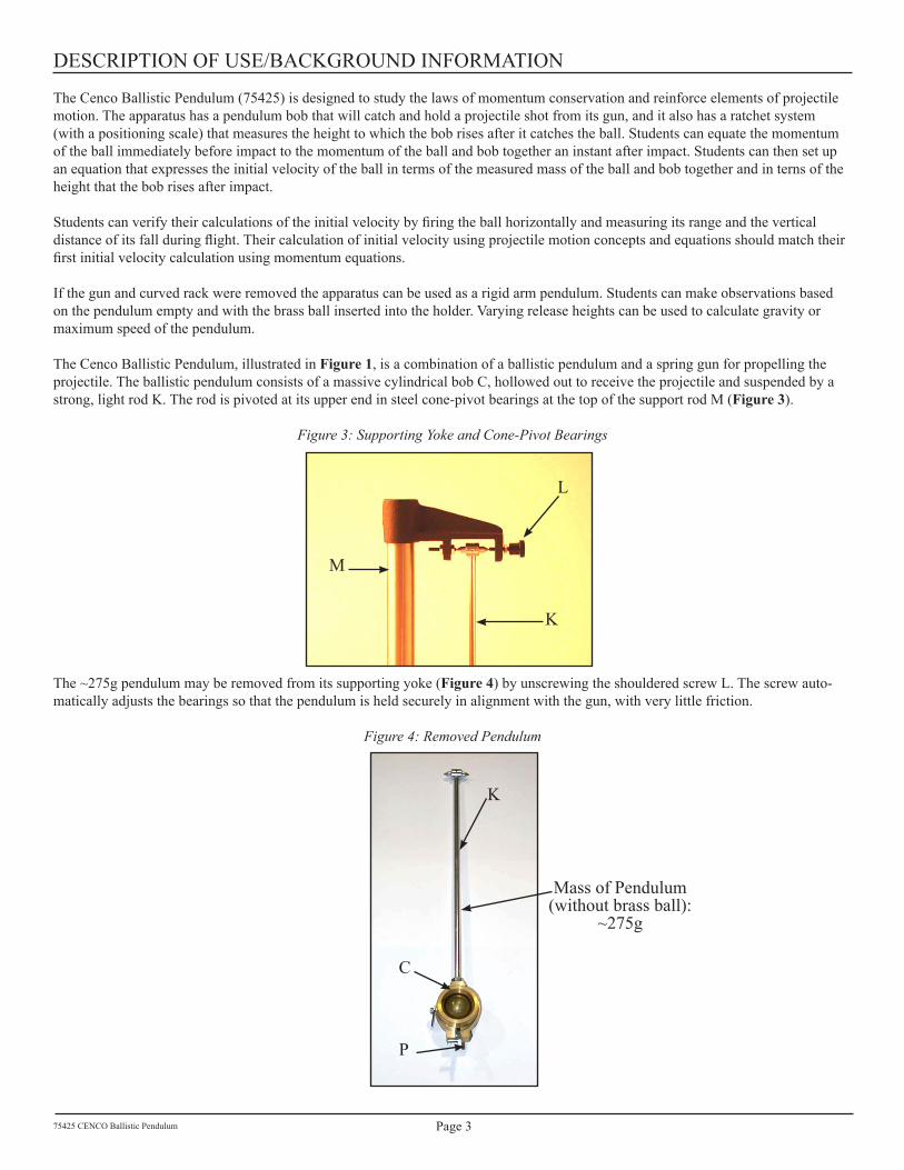
the Cenco Ballistic Pendulum, illustrated in Figure1, is a combination of a ballistic pendulum and a spring gun for propelling the projectile. the ballistic pendulum consists of a massive cylindrical bob C, hollowed out to receive the projectile and suspended by a strong, light rod K. the rod is pivoted at its upper end in steel cone-pivot bearings at the top of the support rod M (Figure3).
Figure 3: Supporting Yoke and Cone-Pivot Bearings
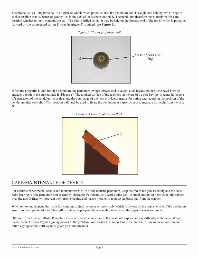
the ~275g pendulum may be removed from its supporting yoke (Figure4) by unscrewing the shouldered screw l. the screw auto-matically adjusts the bearings so that the pendulum is held securely in alignment with the gun, with very little friction.
Figure 4: Removed Pendulum
M
K
l
K
P
C
Mass of Pendulum (without brass ball):
~275g
75425 CENCO Ballistic Pendulum Page 4
the projectile is a ~70g brass ball B (Figure5) which, when propelled into the pendulum bob, is caught and held by two O-rings in such a position that its center of gravity lies in the axis of the suspension rod K. the pendulum therefore hangs freely in the same position whether or not it contains the ball. the ball is drilled so that it may be held on the forward end of the rod H which is propelled forward by the compressed spring E when he trigger T is pulled (see Figure1).
Figure 5: Close-Up of Brass Ball
When the projectile is shot into the pendulum, the pendulum swings upward and is caught at its highest point by the pawl P which engages a tooth in the curved rack R (Figure6). the toothed surface of the rack lies on the arc of a circle having its center in the axis of suspension of the pendulum. a scale along the outer edge of the rack provides a means for noting and recording the position of the pendulum after each shot. This position will later be used to fixate the pendulum at a specific spot to measure its height from the base N.
Figure 6: Close-Up of Curved Rack
CarE/MaINtENaNCE Of dEVICE
for accurate experimental results and to maximize the life of the ballistic pendulum, keep the rod of the gun assembly and the cone-point bearings of the pendulum arm assembly lubricated. Petroleum jelly works quite well. a small amount of petroleum jelly rubbed over the two O-rings will prevent them from cracking and makes it easier to remove the brass ball from the catcher.
When removing the pendulum arm for weighing, adjust the outer setscrew only, which is the one on the opposite side of the pendulum arm from the support column. this will maintain proper pendulum arm alignment when the apparatus is re-assembled.
Otherwise, the Cenco Ballistic Pendulum needs no special maintenance. If you should experience any difficulty with the pendulum, please contact Cenco Physics, giving details of the problem. your business is important to us. to ensure maximum service, do not return any apparatus until we have given you authorization.
Computer technology has greatly aided the study of scientific experiments. Below is a general guide to use Probeware to enhance the lab experience.
�. required equipment Photogate timers (2 if used in pulse mode, � if used in gate mode)
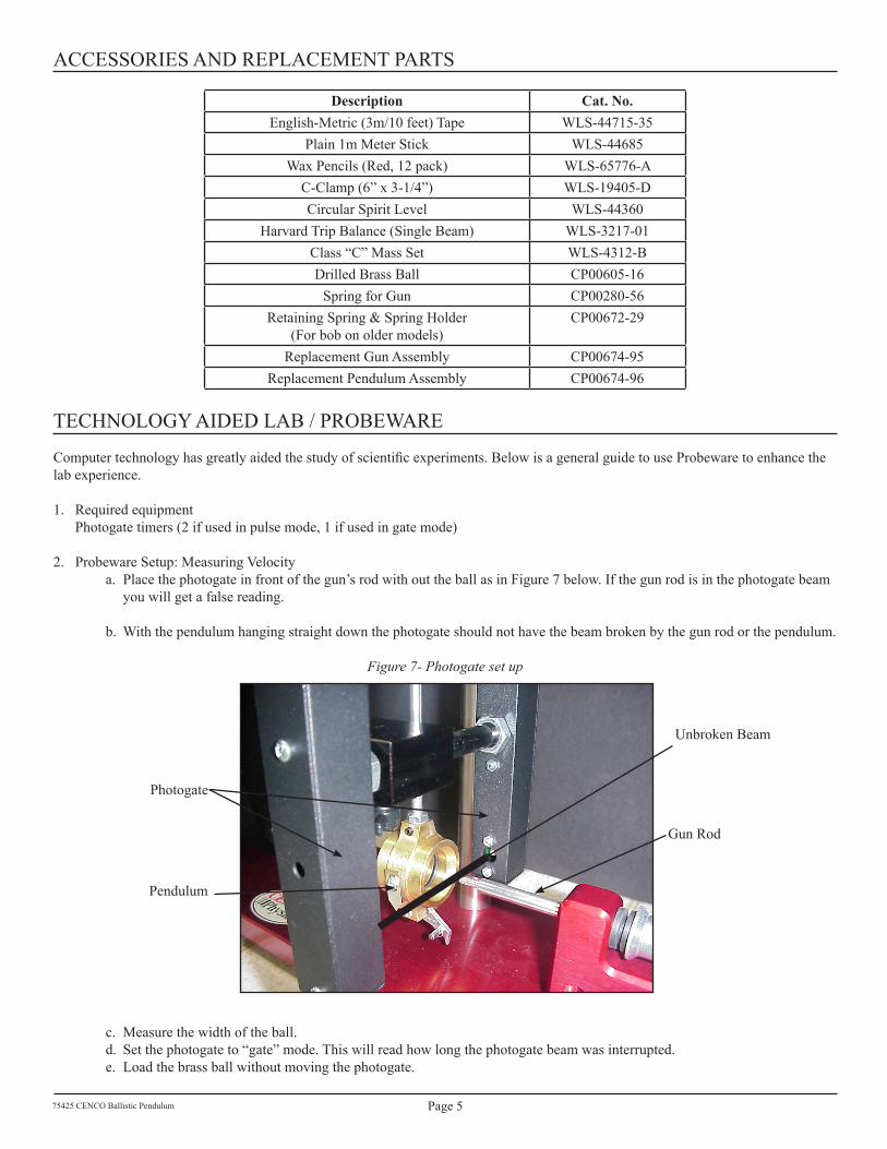
2. Probeware setup: Measuring Velocitya. Place the photogate in front of the gun’s rod with out the ball as in figure 7 below. If the gun rod is in the photogate beam
you will get a false reading.
b. With the pendulum hanging straight down the photogate should not have the beam broken by the gun rod or the pendulum.
Figure 7- Photogate set up
c. Measure the width of the ball.d. set the photogate to “gate” mode. this will read how long the photogate beam was interrupted. e. load the brass ball without moving the photogate.
gun rod
Pendulum
Photogate
unbroken Beam
75425 CENCO Ballistic Pendulum Page 6
f. fire the brass ball and record the time.g. With the time and width of the ball you can calculate the velocity of the brass ball.
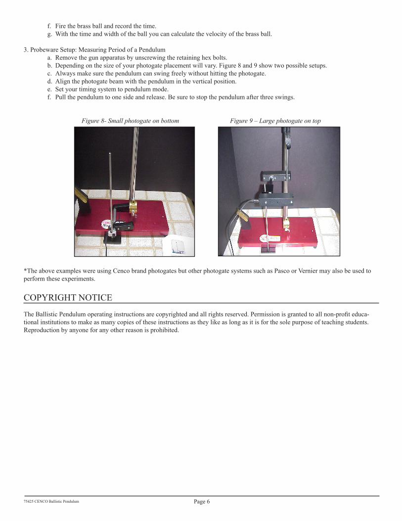
3. Probeware setup: Measuring Period of a Penduluma. remove the gun apparatus by unscrewing the retaining hex bolts.b. depending on the size of your photogate placement will vary. figure 8 and 9 show two possible setups.c. always make sure the pendulum can swing freely without hitting the photogate.d. align the photogate beam with the pendulum in the vertical position.e. set your timing system to pendulum mode.f. Pull the pendulum to one side and release. Be sure to stop the pendulum after three swings.
Figure 8- Small photogate on bottom Figure 9 – Large photogate on top
*the above examples were using Cenco brand photogates but other photogate systems such as Pasco or Vernier may also be used to perform these experiments.
COPyrIght NOtICE
The Ballistic Pendulum operating instructions are copyrighted and all rights reserved. Permission is granted to all non-profit educa-tional institutions to make as many copies of these instructions as they like as long as it is for the sole purpose of teaching students. reproduction by anyone for any other reason is prohibited.
The momentum p of a body is defined as the product of the mass m of the body by its velocity v. In symbols, the defining equation is
p = mv (Equation �)
It may be shown from Newton’s second and third laws of motion that momentum is conserved in all impacts. the principle of the conservation of momentum implies that the change of momentum of one part of a system must be equal and opposite to the change of momentum of some other part of the system.
the principle of the conservation of momentum may be derived from Newton’s laws of motion as follows: Imagine an object of mass m� moving with a velocity v1 when it strikes a stationary object of mass m2. the deceleration of the first object is, by Newton’s second law of motion, due to the force f1 which the second object exerts upon it. The first object, in accordance with the third law of motion, exerts an equal and opposite force –f2 upon the second body. representing the respective accelerations by a1 and a2,
f� = -f2 and m�a�= -m2a2 (Equation 2)
These forces necessarily act for the same time interval ∆t, where t is the time the two objects are applying a force to one another. From the definition of acceleration
a�=∆v�/∆t and a2 = ∆v2/∆t (Equation 3)
where ∆v� is the change in velocity of the first body and ∆v2 is the change in velocity of the second. substituting these values of the accelerations in Equation (2)
m�∆v� = -m2∆v2(Equation 4)
since the product of mass by change in velocity represents the change in momentum, it follows from Equation (4) that the loss in momentum of the first body is just equal to the gain in momentum of the second body. In other words, the total momentum of the system has remained constant during the impact.
In the present case of inelastic impact it follows from the principle of the conservation of momentum that the momentum of the ball just before impact is equal to the combined momentum of the ball and bob an instant af-ter impact. In the ballistic pendulum used in this experiment the velocity of the pendulum before impact is zero, and hence its momentum before impact is zero. the momentum of the ball before impact is the product of its mass m and its initial velocity v just before impact. since the projectile becomes imbedded in the pendulum bob after impact, the ball and bob an instant after impact have a common velocity V and the combined momentum is (M+m)V, where M is the mass of the bob system (~345g). from the law of the conservation of momentum
total momentum before impact = total momentum after impact
where m = ~70g and M = ~345g, from which the initial velocity is given by
v = [(M + m)V]/m (Equation 6)
as a result of the impact, the pendulum containing the projectile swings about its point of support, and in thus swinging its center of gravity rises through a vertical distance h. Knowing this distance, it is possible to de-termine V. the kinetic energy of the system an instant after impact must, by conservation of energy, equal the increase in potential energy gained by the pendulum when it reaches its highest point. By equating the kinetic energy to the potential energy
2� ( ) ( )2
M m V M m gh+ = + (Equation 7)
from which
2V gh= (Equation 8)
By means of Equation (8), V may be calculated from the measured height h. this value, together with the masses M (~345g) and m (~70g), can be substituted in Equation (6) for the computation of v.
B.Setup/Procedure
�. set the apparatus near one edge of the table. If necessary, wedge it up with cardboard until the base in ac-curately horizontal, as shown by the level. Clamp the frame to the table. (refer to Figure1 for Complete apparatus labels)
2. to ready the gun for shooting, rest the pendulum on the rack r, put the ball in position on the end of the rod h and, holding the base with one hand, pull back on the ball with your other hand until the collar on the rod H engages the trigger T. This compresses the spring E a definite amount, and the ball is given the same initial velocity every time the gun is shot (FigureS1).
Figure S1: Proper Set-Up for the Loaded Spring Gun
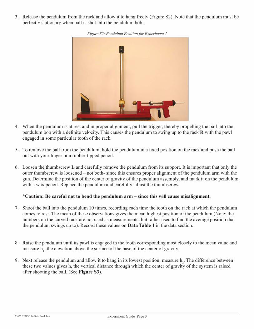
3. release the pendulum from the rack and allow it to hang freely (figure s2). Note that the pendulum must be perfectly stationary when ball is shot into the pendulum bob.
Figure S2: Pendulum Position for Experiment 1
4. When the pendulum is at rest and in proper alignment, pull the trigger, thereby propelling the ball into the pendulum bob with a definite velocity. This causes the pendulum to swing up to the rack R with the pawl engaged in some particular tooth of the rack.
5. To remove the ball from the pendulum, hold the pendulum in a fixed position on the rack and push the ball out with your finger or a rubber-tipped pencil.
6. loosen the thumbscrew L and carefully remove the pendulum from its support. It is important that only the outer thumbscrew is loosened – not both- since this ensures proper alignment of the pendulum arm with the gun. determine the position of the center of gravity of the pendulum assembly, and mark it on the pendulum with a wax pencil. replace the pendulum and carefully adjust the thumbscrew.
7. shoot the ball into the pendulum �0 times, recording each time the tooth on the rack at which the pendulum comes to rest. the mean of these observations gives the mean highest position of the pendulum (Note: the numbers on the curved rack are not used as measurements, but rather used to find the average position that the pendulum swings up to). record these values on DataTable1 in the data section.
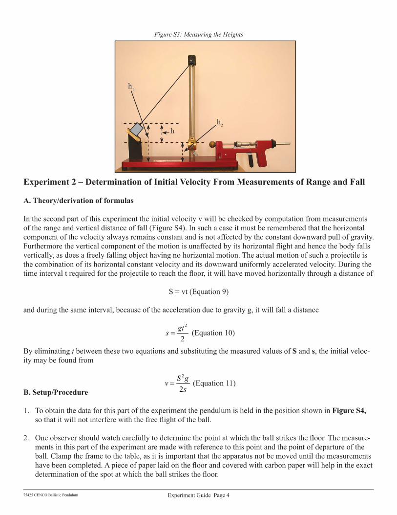
8. raise the pendulum until its pawl is engaged in the tooth corresponding most closely to the mean value and measure h�, the elevation above the surface of the base of the center of gravity.
9. Next release the pendulum and allow it to hang in its lowest position; measure h2. the difference between these two values gives h, the vertical distance through which the center of gravity of the system is raised after shooting the ball. (see FigureS3).
In the second part of this experiment the initial velocity v will be checked by computation from measurements of the range and vertical distance of fall (figure s4). In such a case it must be remembered that the horizontal component of the velocity always remains constant and is not affected by the constant downward pull of gravity. Furthermore the vertical component of the motion is unaffected by its horizontal flight and hence the body falls vertically, as does a freely falling object having no horizontal motion. the actual motion of such a projectile is the combination of its horizontal constant velocity and its downward uniformly accelerated velocity. during the time interval t required for the projectile to reach the floor, it will have moved horizontally through a distance of
s = vt (Equation 9)
and during the same interval, because of the acceleration due to gravity g, it will fall a distance
2
2gts =
(Equation �0)
By eliminating t between these two equations and substituting the measured values of S and s, the initial veloc-ity may be found from
2
2S gv
s=
(Equation ��)
B.Setup/Procedure
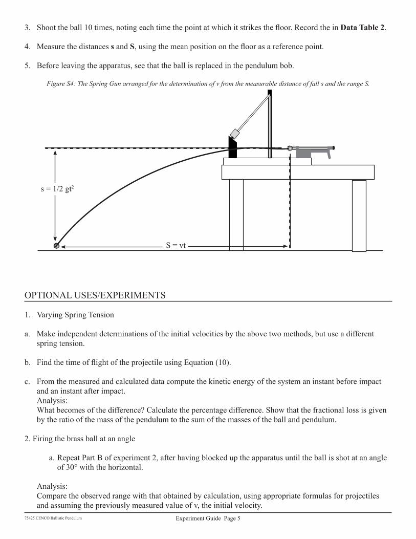
�. to obtain the data for this part of the experiment the pendulum is held in the position shown in FigureS4, so that it will not interfere with the free flight of the ball.
2. One observer should watch carefully to determine the point at which the ball strikes the floor. The measure-ments in this part of the experiment are made with reference to this point and the point of departure of the ball. Clamp the frame to the table, as it is important that the apparatus not be moved until the measurements have been completed. A piece of paper laid on the floor and covered with carbon paper will help in the exact determination of the spot at which the ball strikes the floor.
POst laB QuEstIONs �. suggest some probable reason for the difference between the values of v as obtained by the two methods.
2. What might be the procedure to determine the “efficiency” of the spring gun, i.e., the ratio of its energy out-put to the work done upon it?
3. What becomes of the momentum of a meteorite, which comes into the earth’s atmosphere? a. What happens to its kinetic energy?
b. Imagine a meteorite that explodes in space. What happens to the center of gravity of a collection of meteorite pieces from an exploded meteorite compared to the center of gravity of the unexploded meteorite?
c. What is the effect on the center of gravity of a meteorite if it explodes within the earth’s atmosphere?
4. Note the percentage difference between the values of v determined by the two methods. try to analyze the probably errors of the two methods and estimate which one should give the more accurate result.