77
OPERATING INSTRUCTIONS FOR 350 Series Carousel® Manufactured By lr SONO MAG CORP. 1019 W. Washington St., Bloomington, Ill. U.S.A. 61701 3 o°\- Lia - ).3
| Date post: | 09-Mar-2018 |
| Category: |
Documents |
| Upload: | nguyenngoc |
| View: | 218 times |
| Download: | 1 times |

OPERATING INSTRUCTIONS FOR
350 Series Carousel®
Manufactured By
lr
SONO MAG CORP. 1019 W. Washington St., Bloomington, Ill. U.S.A. 61701
3 o°\- Lia - ).3

TABLE OF CONTENTS
350 SERIES CAROUSELS
SECTION 1 Equipment Description P. 1 -1
SECTION Z Installationt& Connections P. 2 -1
SECTION 3 Operating Controls. P. 3 -1
SECTION 4 Theory of Operation P 4 -1 Power Supplies P. 4 -1 Program Amplifiers P 4 -2 Cue Control System P. 4 -3 Logic Control Circuits P 4 -5 Motor Logic P 4 -6 Motor Control P 4 -6 Motor Control Indicators, Fig. 4 1 P 4 -7 Model 350 -RSB Random Select P 4 -8
SECTION 5 Electrical Maintenance P 5 -1 Adjust 150 150 Hz Sensor P 5 -2 Adjust 1 KHz P 5 -3 Adjust 4 KIIz P 5 -4 Miscellaneous Chassis Connectors P. 5 -4 Section 5 Illustrations P 5 -6
SECTION 6 Mechanical Adjustments. P 6 -1 Solenoid Operatior P 6 -1 Pinch Roller Adjustment P 6 -1 Cross Shaft Adjustment P 6 -3 Tape I -lead Adjustment P 6 -4 Capstan Motor P 6 -5 Lubrication & Cleaning P 6 -5 Tray Index. P 6 -6 Drum Motor P 6 -8 Figure 6.1; 6.2 Carousel P. 6 -9 Figure 6.3; 6.4; 6.5 Carousel P 6 -10 Figure 6.6 Model 305A Transport. P 6 -11 Figure 6.7 Head Mount Illustration P 6 -13 Figure 6.8 Head Mount HB -10 P 6 -14A
SECTION 7 Parts List P 7 -1
SECTION 8 Master Schematic - RS Master Schematic - RSB
SONO -MA G CORPORATION
BLOOMINGTON, ILLINOIS USA
12 -76 090 -0008 -001

This Kook contains CONFIDENTIAL INFORMATION
This book, and the drawings contained herein, contain confidential information proprietary to Sono -Mag Corporation. In consideration of the receipt of this book, the recipient agrees not to reproduce, copy, transmit, or reveal information contained therein in whole or in part, or to suffer such action by others for any purpose except with written permission first obtained of Sono -Mag Corporation, and further agrees to surrender same to Sono -Mag Corporation upon demand.
Sono -Mag Corporation Bloomington, Illinois USA June, 1975

SECTION I
EQUIPMENT DESCRIPTION
1.1 INSTRUCTION MANUAL: This Instruction Manual covers the
Installation, Operation and Maintenance of the following SMC cartridge equipment:
350 Monophonic Carousel Playback 352 Stereophonic Carousel Playback
The above model numbers followed by -RS indicate that random select tray identification (decimal) switch unit is installed.
-RSB suffix indicates BCD random select system.
1.2 GENERAL DESCRIPTION: The Logi -Cart series of Carousel equipment features interlocked control of all operating functions using logic circuitry. Switching is solid -state; all relays have been eliminated.
I lysteresis- Synchronous capstan motors provide direct tape drive, assuring timing accuracy and low wow and flutter. Circuit boards and integrated circuit components are plug -in. Provision for alpha- numeric logging is also standard.
The Carousel is a magnetic tape playback system which can move mechanically into playing position any of 24 cartridges (NAB Type A ) that are stored in its revolving drum. The standard Carousel will, upon returning to the beginning of the endless tape loop where a cue control signal has been recorded, stop the tape drive and automatically remove that cartridge from the playing position and move to the next cartridge, insert it ready for a start command. This sequence pro- cedure is repeated each time a cartridge is played.
1.3 SPECIFICATIONS
1.3.1 ALL U NITS
Tape Speed: 71 Inches per second (19.05 CMPS) Output: 600 ohms, balanced
12 dBm before clipping Normally O dBm (al NAB Reference
Playback Distortion: Less 1% © dBm, 400 I -Iz NAB reference
Frequency Response: + 2dB, 50 Hz to 15 kI -Iz Equalization: NAB, adjustable for head wear
1 -1

Speed Accuracy: 99.8% or better Aux (Secondary) Cue: 150 Hz TIT output, and open collector output. Logging Sensor: 4 Kliz nominal; TIT output Head Configuration: In accordance with NAB specifications Cartridge capacity: ( #300) 24 Time capacity: 40 Sec. to 10 Min. per cartridge Shift time (from cue on one cartridge to ready for next
cartridge) : 4 Seconds Time for 360 degree rotation and insert of cartridge (with
Random Selector Control) : 21 Sec Cal 60 Hz - 25 Sec Cal 50 Hz Power: 115V 60 Hz 2 amp. Dimensions: Rack mounts, 20" W x 191,4" H x 18" D
50.7 CM x 49 CM x 45.7 CM Weight: 90 Pounds (41 Kg.)
1 -2

SECTION 2
I NSTALLATION
2.1 UNPACKING & INSTALLING
NOTE: Damage claims should be filed promptly with the carrier. All packing material should be retained until the inspection is complete.
Open crate by removing screws from top and remove two rack - mounting panels and front escutcheon assembly.
Remove any packing around mechanism being careful not to bend cart- ridge tray holders.
FOR RACKS WITH FRONT RAILS ONLY:
1. Use 81/2" tall carrier panel and fasten to inside of rack rail with #10 screws, washers, lockwashers and nuts. Panels fit at top of 193" opening with installed Carousel mounting angles at the bottom of the panels and facing toward center of rack.
2. Install four escutcheon mounting clips with #10 screws through slots and tapped holes in clips facing center of rack. Center of clips will be 11/2" from 191" required opening.
FOR RACKS WITH FRONT AND REAR RAILS:
1. Use 4" wide carrier rail with adjustable rear mounting flange.
2. Measure down 6 3/4" from 193/4" required opening. Bolt carrier rail at front and rear with #10 screws. Installed Carousel mounting angle will be near upper edge of carrier rail and facing center of rack. 3. Install four escutcheon mounting clips with #10 screws through slot into front rails. Center of clip will be 11" from top and bottom of 191" opening.
A. Remove all cables from Carousel electronic chassis. B. Remove three screws in top lip of chassis and lift chassis
straight up and set aside. C. Remove crate clip nearest capstan motor and remove 5/16
bolts at left end of Carousel frame.
D. Carefully lift Carousel by grasping channel assembly straight up and out of crate. Lift into rack through rear door and rest right -hand end of channel on support angle which is bolted to rack panel. Unit can then be moved into position on the left. This unit weighs about 90 lbs. Assistance from the front of the rack to support the weight at the rim of the drum is helpful.
E. Fasten the channel to the angles with the 5/16" bolts and tighten when the drum is centered in the opening of the rack.
2 -1

F. Install electronic chassis with t18 screws to the channel frame so that the chassis is horizontal and with amplifier units at your left. Plug into chassis sockets the appropriate cable plugs. Double check. Install head cables into proper chassis jacks.
2.2 ESCUTCHEON MOUNTING
Four right angle clips are bolted to front side of rack rails with #10 screws so that the tapped holes in the clips face toward center of rack.
Feed cables and plugs over top of drum and install escutcheon with four #8 screws to clips just installed.
Be certain to match plugs and sockets in electronic chassis.
Carousel drum must be centered in escutcheon so that no rubbing will occur.
2.3 EXTERNAL CONNECTIONS
2.3.1 CONNECTOR SO -1: Connector SO -1 is used on all units. Connections are as follow:
Terminal 1: Left (or mono) Audio out 2: Left (or mono) Audio out 3: Audio Ground 4: Stereo, Right Audio out 5: Stereo, Right Audio out 9: 5.1 vdc, plus
10: 150 -4000 I Iz Sensor Enable 11: Remote start 12: Ground 13: Secondary (Auxiliary) Cue out 14: Secondary (Auxiliary) out, Open Collector 15: Logging out
NOTES: 1. In Stereophonic use, Terminals 1 -4 and 2 -5 are in phase.
2. Outputs at Terminals 13 and 15 are active only when these circuits are enabled by a logic 1 applied to Terminal 10. All units are supplied with a connector having an enable strap between Terminals 9 and 10. In automation systems these circuits are usually enabled by a "now playing" signal from the system.
2-2

3. Outputs at Terminals 13 and 15 are high (logic 1) with signal detection.
4. Application of a "ground" to Terminal 11 will cause the unit to start.
5. Terminal 14 connects directly to the open collector of an NPN transistor which has a grounded emitter. This transistor conducts when a 150 ';z tone is de- tected. This will furnish a "ground going" circuit which may be used as a "start switch" for other - equipment. NOTE: This circuit is intended ONLY for switching 21 vdc, or less, and is limited to a 40 milliampere load. If used to switch a relay or other inductive devices a transient suppressor, such as a diode, should be used across the load to protect the transistor.
2.3.2 ARMING CONNECTOR SO - 3 ( -RS MODELS)
Terminal 1: 24 v. -dc +
2: RS Link 3: . Play eject enable 4: No. connection 5: Play (Lagic 1 on play) 6: Cart sense switch 7: Reject (apply +24 to eject tray) 8: Ground 9: Eject control
NOTES: 1. Closing the RS link (pins 1 and 2) when the correct tray is indexed will shift in the desired tray.
2. Pin 3 is held at ground to allow reject at end of play in Random mode. Ground this pin when using RSC -50 controler.
3. Pin 9 can he grounded to hold tray in place after play. Release ground to allow tray to eject.
2 -3

'').3.3 ARMING CONNECTOR SO-2 (13CD ARM INPUT)
Terminal 1: Aux tone (active low) 2: Ground 3: "1" tray bit 1: "2" tray bit 5: "4" tray bit 6: "8" tray hit 7: "10" tray bit 8: "20" tray hit 9: Aux Tone (active high) 10: Arm command (active low) 11: Reset (Active high) 12: -15: No Connection
3.3.1. BCD SWITCI I INPUT
Terminal 1: "10" -RSB input "20" -RSE; input
3: " 1" -RSE' input 4: " 8" -RSB input 5: " 1" -RSB input 6: " 2" -RSI3 input 7: +5 volts DC 8: Ground 9: No connection
-4

SECTION 3
OPERATION
3.1.1 POWER SWITCH: On all units the main AC switch is on the front panel.
Operator controls are located on the front escutcheon of the unit and their functions are as follows:
MANUAL This switch is moved to up position to give operator control of drum rotation (with Rotate button) . It is pressed again to return unit to normal sequence operation. (down)
ROTATE If MANUAL switch is in the manual state, the ROTATE button will cause drum to turn clockwise for as long as button is depressed. After its re- lease, drum will turn to next tray that is properly indexed.
START This button will start the playing of the inserted cartridge. Lighted during play.
STOP This button will stop the playing of a cartridge. If the MANUAL switch has been pressed the STOP button will not cause the cartridge to be withdrawn after it is stopped from playing. Lighted with power on.
TRAY If MANUAL switch is in the manual state, the tray button will cause the cartridge to be withdrawn when- ever cartridge is not running and inserted when properly indexed.
In the MANUAL mode, a cartridge may be started and stopped repeatedly and then withdrawn by the TRAY button. This permits testing, alignment, etc.
3.1.2 RANDOM /SEQUENCE SWITCH
The sequential mode or random select mode of the Carousel can be selected with the toggle switch on the rear chassis. In the Seq. position, the Carousel will operate in the sequential mode. When in the Random position, the Carousel will rotate after the tray ejects until external equipment programs the next tray to be selected.
3 -1

SECTION 4
THEORY OF OPERATION
4.1 GENERAL
4.1.1 SCHEMATICS: Schematics of all equipment to be described in this section will he found in Section 8.
4.1.2 LOGIC DEFINITIONS: To simplify the explanation of the 350 series cartridge equipment, certain basic logic terms will he used. These are defined below:
1. Logic 1: The high voltage state, typically in the order of 3.3 to 5.1 volts.
2. Logic 0: fhe low voltage state, typically in the order of 0.0 to 0.8 volts.
4.1.3. PRINTED CIRCUIT ASSEMBLIES: Printed circuit hoard assemblies furnished are as follow:
ALL UNITS: PS -24B Power Supply PR -2 Playback Amplifier SA-1 Index Sense Amplifier CSC Control Sensor LC -1 Logic Control ML-1 Motor Logic MC -3 Motor Control CL-1 BCD Comparator ( -RSB Models)
4.2 POWER SI' PPLIES
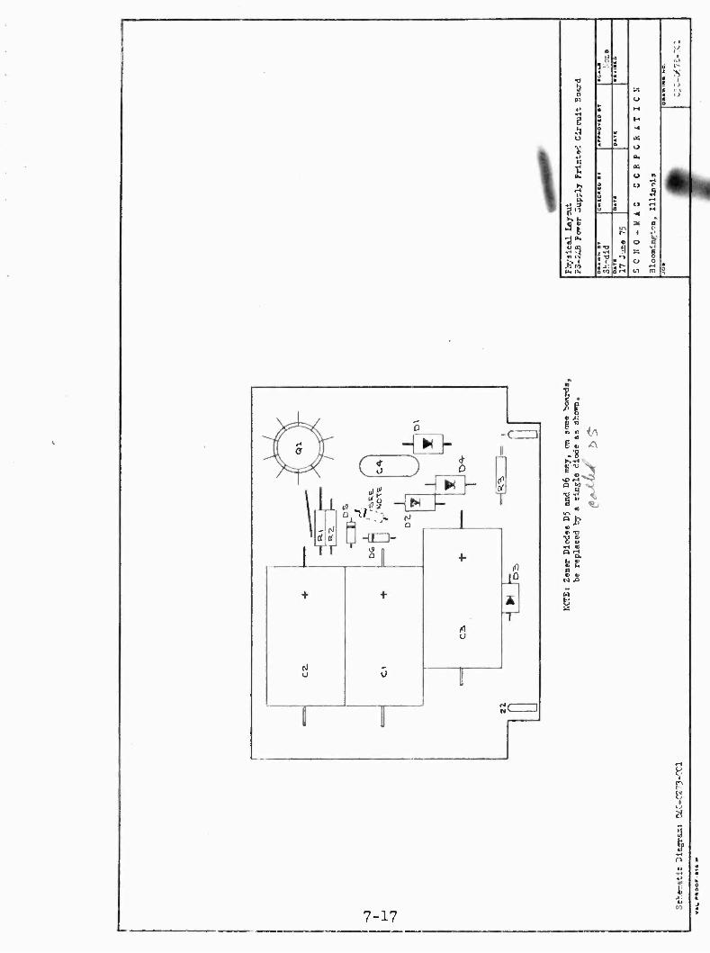
4.2.1 PS -24B SUPPLY : The 24 volts supply consists of four diodes arranged in a bridge configuration. The output is regulated by transistor Q1 and Zener diodes D5-D6.
4.2.2 VCC LOGIC SUPPLY: The logic power supply consists of an integrated circuit bridge rectifier and associated filter furnishing approximately 13 volts to an integrated circuit voltage regulator. Output of the regulator is 5.1 volts.
4.2.3 SG-1A SOLENOID GATE ASSEMBLY : The solenoid power supply is part of the SG -1 Solenoid Gating Assembly located on the underside of the tape transport. The SG-1A consists of an SCR controlled by a photo- coupled trigger device. Output is 95 volts + 5 volts. Since this assembly is connected to the primary power source,a metal protecting cover is furnished.
The motor capacitor is also located on the SG-1A board.
4 -1

4.3 PR -2 PROGRAM AMPLIFIER: The PR -2 Program amplifier consists of IC -1, a dual low noise integrated circuit preamplifier, followed by output transistors 1Q1 for the left channel (or monophonic) and 2Q1 for the right channel. Gain controls 1R2 and 2R2 are for left and right channels respectively. Variable resistors 11215 and 2R15 are high frequency compensators for the left and right channels. NOTE: The input to the right channel preamplifier is grounded in monophonic units.
Connections to this board are as follow:
Terminal 1: Left preamplifier out 2: Left output amplifier in 3: 24 volts +
4: Left amplifier out 8: IC Ground 9: Left preamplifier in
11: Ground 12: Power Ground 13: IC Ground 15: Right preamplifier in 17: 24 volts +
19: Right amplifier out 20: 24 volts +
21: Right output amplifier in 22: Right amplifier out
4.4 INDEX SENSE AMPLIFIER: In the 350 Series (not -A) the tray index system photo reflective from machined and polished segments in the rear of the Carousel drum casting.
A printed circuit board, SA -1 is mounted below the drum bearing block on an adjustable assembly. This board has an infra -red (invisible) reflection sensor and amplifier transistors. A LED indicator is on this board to show the sensing of the right hand edge of the drum segment. It will be "ON" when the tray is at index and flash on and off as the drum turns .
The distance from the sensor Q3 to the segment surface should be 0.150 to 0.187 inches and the sensor axis must be square to the drum . When adjusting this to right or left, do not change the angle or distance. See Fig. 6.4 and Section 6.8.
4 -2

4. 1 CSC -1 CONTROL SENSE CIRCUIT
4.4.1 GENERAL: The CSC -1 Control Sense Circuit assembly ampli- fies all control signal information recorded on a cartridge cue track, converts this information to di ital form and controls the resulting sig- nals.
The CSC assembly provides switching circuits which enable, or inhibit, transmission of logging and secondary (auxiliary) signals as required. In routine operation these signals are enabled at all times; however, in
automation systems the outputs are usually inhibited except when the program source is actually on the air. This permits auditioning of cart- ridges but prevents transmission of switching information.
IC -1 is a single Integrated Circuit package containing two identical high
gain amplifiers. The output of the cue playback head feeds the input of
both amplifiers. Section A of IC -1 is used as an amplifier for 1000 Hz
cue and 4000 Hz logging signals. Section 13 is a 1.50 IIz secondary cue selective amplifier in a "twin T" configuration.
4.4.2 1000 HERTZ CUE SECTION: The output of the 1000 -'000 Hz amp- lifier, IC -1 section A , is clipped by diodes D3 and D4 anc. fed to the in- put of EC -3, an NE -567 phased -lock loop tone decoder. The center frequency of the decoder detection band is set at 1000 HZ by variable resistor R26. Detection of a 1000 Hz cue signal causes the decoder output (board terminal 21) to change from high (logic 1) to low (logic 0) for the duration of the tone.
4.4.3 4000 HERTZ SECTION: The clipped output of the 1000 -4000 1 IZ
amplifier is fed to the input of tone decoder IC -4. The center frequency of the decoder detection band is set at 3850 -3890 IIz by variable re- sistor R 29. Detection of a 4000 Hz causes a low (logic 0) signal to ap- pear at board terminal 20.
4000 HERTZ ENABLING CIRCUIT: The 4000 1 l logic 0 signal appearing at board terminal 20 re- enters the CSC assembly on terminal 5 where it is routed to pin 6 of IC -2 section D. Section D is a two input NOR
gate; both inputs must be at logic 0 to produce a logic 1 output. The
second input is controlled by transistor Q3. When a logic 1 is applied to the base of Q1, via board terminal 6, a logic O appears at IC -2 pin 5. Therefore, when the circuit enabling logic 1 is applied to board terminal 6 AND a 4000 Hz signal is detected, a logic 1 appears at out- put board terminal 4.
4 -3

4.4.4 150 HERTZ SECONDARY CUE SECTION: The center frequency of the 150 Hz detection band is set by variable resistor R5. The output of the 150 Hz amplifier, IC -1 section B, is rectified by diodes D1 and D2 and thus controls switching transistor Ql. The output of Q1 is properly shaped by sections A and B of IC -2. A logic 0 appears at the output of section B during detection of a 150 Hz tone.
150 HERTZ ENABLING CIRCUIT: The two inputs of IC -2 section C, must be at logic 0 to produce a logic 1 output. It can be seen that this condi- tion exists when a 150 Hz tone is detected AND the enabling logic is applied to board terminal 6.
4.4.5 150 HERTZ SWITCHING CIRCUITS: The CSC assembly provides three output switching circuits which are activated by the 150 Hz tones. As previously described, IC -2 provides a signal at logic level. This same signal controls transistor Q4 which provides an open collector, general purpose switching circuit. Both of these circuits are controlled by the board inhibit -enable system. A third output is provided by tran- sistor Q2 and is used in Record Centers as a switch for the secondary cue lamp indicators; this circuit is enabled at all times.
4.4.6 BOARD TERMINALS: Functions of the CSC -1 board terminals are as follow:
Terminal 1: VCC, plus 5 volts 2: Ground 3: To 150 Hz indicator in Record Centers 4: 4000 Hz logging output 5: 4000 Hz logging from Terminal 20 6: 150 -4000 Hz enable 7: 150 Hz logic out 8: Ground 9: 150 Hz switch, open collector
11: Ground 14: 24 volts +
15: Cue Head input 17: Ground 19: VCC, +5 volts 20: 4000 Hz logic signal to pin 5
21: 1000 Hz logic signal out 22: Ground
4 -4

1.5. LC -1 LOGIC CONTROL BOARD
4.5.1. GENERAL: The LC-1 Logic Control board is the switching center for all record and playback functions. Basically, the LC -1 consists of two flip -flop s which control the stop -run and record - playback modes. The input and output circuits of these flip - flops are controlled by additional logic which inhibit or enable the switch- ing functions as required.
Some circuits on the LC -1 hoard are used only in recorder models.
The logic states of the circuits are shown in Fig. 5 -9.
4.5.2 START -STOP FLIP- FLOP
STOP MODE: In the STOP mode (tape not running) IC -2A pin 8 is at logic 0 and IC -213 is at logic 1. Transistor Q4 is conducting; the STOP indicabr is ON.
START -RUN MODE: Two start inputs are provided: (1) board terminal 8 for the front panel START switch and (2) board terminal 19 is used for external start circuits such as automation systems or remote control. A momentary logic 0 applied to either input will cause the start -stop flip -flop to reverse output conditions with pin 8 going high and pin 12 low. The following conditions will then exist:
1. Transistor Q4 becomes non -conducting; the STOP indicator if OFF.
2. Transistor Q2 conducts; solenoid drive is provided.
3. Transistor Q3 conducts; the START indicator is ON.
4. IC -4,fu nctioning as a timer, is triggered by a "one shot" pulse thru capacitor C9. Pin 3 goes high for approximately 2 seconds and inhibits 1000 Hz cue gate IC -333 which prevents machine stoppage during the initial tape start. An additional output is provid- ed during this time at hoard terminal 5 which will be considered later.
STOP CIRCUIT: To stop tape drive, the start -stop flip -flop must be re -set to the off condition. Two reset circuits are provided: (1) from the front panel STOP switch and from the motor logic ML-1. If either line goes low the flip -flop will reset; all circuits revert to the STOP mode.
4 -5

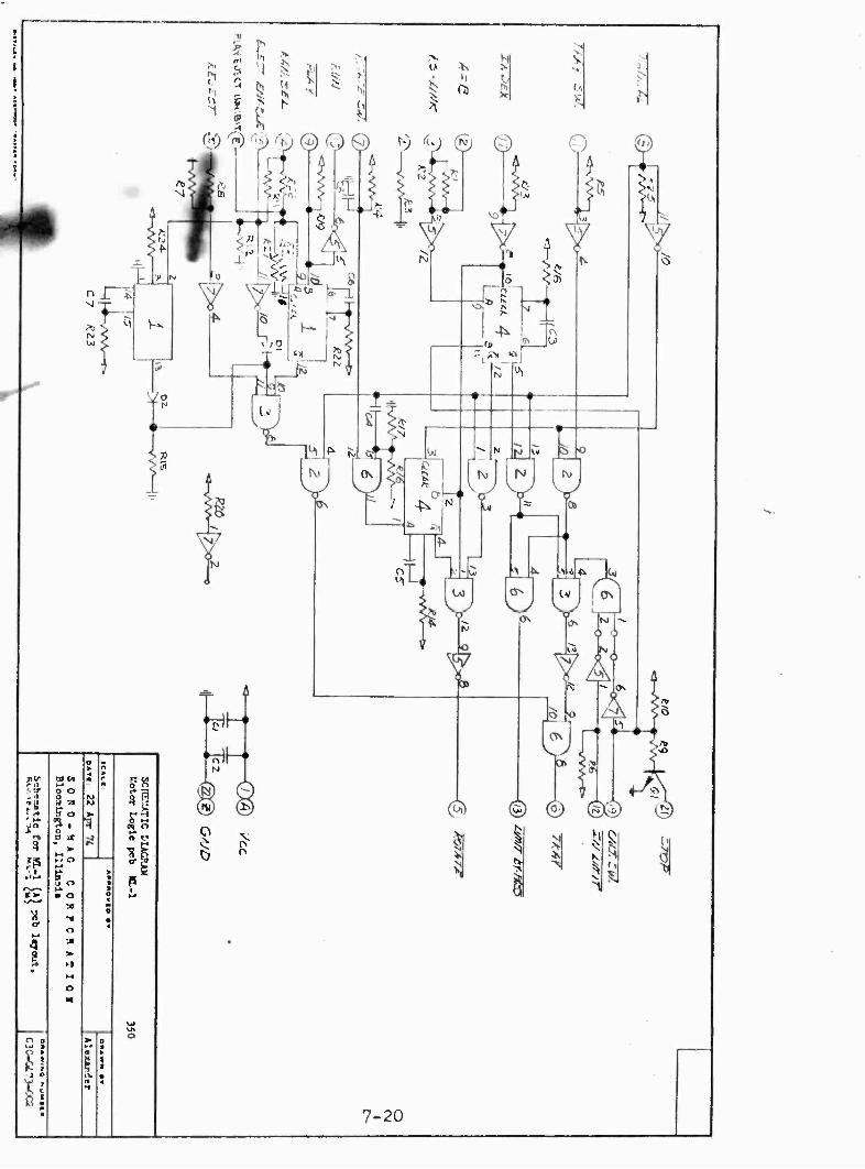
4.6 ML-1 MOTOR LOGIC
4.6.1 GENERAL: The ML-1 pcb performs two major and several minor functions. The various position indicators, control panel switches, logic functions and external commands are logic inputs to the ML-1.
4.6.2 AUTOMATIC MODE: When the Carousel is in the AUTO mode, manual control from the front panel is inhibited. Control then comes from external circuitry in the random select mode or internal circuitry in the sequential mode. The random select /sequential mode is switch selectable from the chassis mounted RAN /SEQ switch. In sequential, the tray is ejected after playing. In random select the tray is held in position until external circuitry releases it. To select the tray, in random select, the 24 position RS- switch is used with external circuitry to close the RS -link (pins 1 and 2 SO -3) . In sequential, the RAN /SEQ switch holds a +24 volt signal on pin 3 of the ML-1 pcb.
4.6.3 MANUAL MODE: In manual, the front panel controls the action of the Carousel. The external shift - rotate control is inhibited in manual. External start commands, however, are not inhibited in the manual mode.
4.7 MC -3 MOTOR CONTROL
4.7.1 GENERAL: The motor control pcb provides further decision making logic which controls the tray and rotate motors. The out limit switch and outputs from the ML-1 provide logic inputs to the MC -3.
4.7.2 LOGIC FUNCTIONS: The out limit switch directs control between the tray and rotate motors. When the tray shift mechanism is "in ", the tray motor is enabled. When the tray mechanism is "out ", (as sensed by the out limit switch) the rotate motor is enabled. To shift the tray "in ", the out limit must be over - ridden by the 'limit by -pass' signal from the ML-1.
4.7.3 MOTOR SWITCHING: The current in the tray and rotate motors is switched by solid state switches on the MC -3 pcb.
4.7.4 LED INDICATORS: The three LED's (light emitting diodes) on the MC -3 are provided for trouble -shooting. The LED's are labeled A, B and C on the card cover. The 'A' LED indicates the rotate signal from the ML-1 pcb. The 'B' LED indicates the tray signal from the ML-1 pcb. The 'C' LED indicates the out limit switch OR'd with the 'limit by -pass' signal
from the ML-1.
A table of normal status of the A -13 -C lights is Fig. 4.1
4 -6

FIG. 4. 1
MOTOR CONTROL INDICATORS - MC -3
STATUS OF CAROUSEL A B C
MANUAL TRAY OUT X
MA NUA I. TRAY MOVING IN X X
MANUAL TRAY IN X X
MANUAL TRAY MOVING OUT X
MANUAL ROTATING X X
MA NUA L HOLD TRAY BUTTON Xa X X
A U TO &
RAND. SEL. X X
AUTO &
SEQ. WHILE ROTATING X X
TRAY MOVES IN X X
TRAY MOVES OUT X X X
X = Indicator lighted (a)= At "IN" position
4-7

4.8 GENERAL: Model 350/352 - RSB CAROUSEL
The RSB models of the 350 series Carousel include the standard features of the 350 series, and in addition, a BCD (Binary -coded decimal) system of random selection of the cartridge trays. This BCD random select system provides a memory for the "next" cartridge selection when this information is provided from a pro- grammer, as the DP -1B /C the DP -2 or the RP -1000.
The one -step memory is provided by the additional circuit board in the Carousel, the CL-1 Compari tor- Latch.
In addition to the CL-1 hoard, the RSB Carousel has the random select switch, driven by the drum, coded BCD by a diode matrix board, DM -24, located adjacent to the switch.
One important advantage of the BCD random select system is the im- proved speed of programming. Where a number ,3f Carousels are in a system, the arming information is presented to all in a fraction of a second, rather than up to 70 seconds per Carousel.
4.9 INTERFACE REQUIREMENTS:
When programmed from a DP -1Fi /C the 35) -RSB Carousels require interface electronics Model CCI.
With the RP- 1000, each -RSB Carousel is random selected individually.
With the DP -2, all -RSB Carousels are armed through a common junction box.
4. 10 COMPARATOR / LATCH CIRCUIT BOARD - CL - 1 030- 0545 -002
This circuit board in the 350/352 - RS!. Carousels is used to provide "next tray" arming information that is stored in the two quad latches, IC 1 and IC 4 (74175).
Ile stored information is in BCD form and this information was pro- vided from the external program device, DP -2 etc. The stored informa- tion in these latches is compared with BCD information from ttie random selector switch driven by the Carousel drum. When the information matches, the "RS: link in the rotate circuit is closed by Q3 and that tray is selected.
4 -3

Quad latch, IC 4 stores bits 1, 2, 4, 8 while IC 1 holds bits 10, 20. The BCD data presented to these latches is "clocked" into the latches by the pulse from the Arming Selector board in the CCI interface unit, after this pulse goes low and returns high.
IC - 3 is part of a latch system to permit only the first of a sequence of "Carousel Select" clock pulses to operate the data latches, IC 1 and IC 4. At the end of the clock pulse, this latch prevents the Carousel from arming on the last of a series of data for that machine. A Reset pulse from the DP -2 that preceeds each arming sequence clears this latch to allow correct arming on the next valid data.
In DP -1 B/C and RP -1000 systems the Reset feature is not required and pin 21 on CL-1 remains in a high state.
The output information stored in the data latches is compared with the BCD data from the -RS switch in 7,186 "exclusive or" gates IC 2 and IC 5. The output of these gates goes low when data A = data l3 and Q3 will switch on to close the "RS" link causing that tray to be moved into play position.
When new 11CD data is clocked into the latches and this data does not match the RS switch, Q4 will cause the tray to be ejected and the Carousel will select the new data tray number.
NOTE: The toggle switch on the Carousel chassis must he in the RANDOM position when random select action is being used.
1.11 RANDOM; SELECT SWITCI1 DECODING
The random select switch driven by the Carousel drum is a 24 position decimal device. To convert this to BCD data, a diode matrix board is wired to the switch to produce an active high on one or more of the six BCD lines to the CL-1 Comparator/ Latch board, via SO-5.
1-9

MODEL 350/352 CAROUSEL WI RING ADDITIONS
FOR CONVERSION TO MODEL 350/352 - RSB
(13CD RANDOM SELECT CONTROL)
Add the following circuits to the Model 350/ chassis.
a. 22 -pin card holder for Comparator /Latch PCB, CL-1 b. 15 -pin A mphenol type Arming connector socket, SO-2 c. 9 -pin Amphenol type - RSB switch socket, SO -5. d. Random selector switch, & Matrix board assembly
COLOR PIN NO. TO PIN NO. FUNCTION
ora 1 -A CL-1 VCC tie pt. VCC +5 V. white 22 -Z CL-1 GND tie pt. ground red 15 CL-1 3PS -24B +24 V /DC grn 15 ML-1 18 CL-1 Eject Enable
SO -2 13CD ARMING INPUT SOCKET
yel 1 + 9 CSC -1 AUX. TONE
whi 2 GNd Tie pt. Ground hla 3 7 CL-1 "1" tray bit in bro 4 6 CL-1 "2" tray hit in gra 5 5 CL- 1 "4" tray bit in ora 6 4 CL-1 "8" tray hit in yel 7 2 CL-1 "10" tray hit in gre 8 3 CL-1 "20" tray hit in
9 * 7 CSC -1 AUX. TONE
vio 10 20 CL-1 ARM COMMAND blu 11 21 CL-1 RESET
12 -15 No connection.
* Do not connect to pin #9 in DP -2 Systems. This is used only in RP -1000 Systems.
+ Some models ;normally not used with SMC systems
4 -10

SECTION 5
ELECTRICAL MAINTENANCE AND ADJUSTMENT
5.1 GENERAL: Use extreme care in removing circuit boards or integrated circuit packages from their sockets. Power should he OFF prior to removal. When replacing integrated circuits be absolutely certain they are returned to the proper socket and in the correct direction with IC pin 1 in socket pin 1: reversal will invariably result in immediate destruction of the IC.
5.2 PR -2 PROGRAM AMPLIFIER: Two sets of controls are located on the PR -2 Program Amplifier Board; these are explained below. Refer to Figure 5.1 for control locations.
5.2.1 GAIN CONTROLS: The left (or monophonic) output level is set by 1R2. Stereophonic right channel output is set by 2 R2. The output level is set at 0 dBm while playing the Standard Level portion of an NAB Primary Reference Tape. The output of the unit must be connected to a 600 ohm load during this adjustment. NOTE: This adjustment calibrates the gain of the playback amplifier for several adjustments which will follow.
5.2.2 IIIGH FREQUENCY COMPENSATION: The left channel ( or monophonic) high frequency response is set by variable resistor 1R15 and the right channel by 2R15. These controls should be adjusted ONLY after playback head azimuth has been carefully checked. An NAB Primary Reference Tape should he used for both azimuth and frequency checks. The program amplifier should be properly loaded with 600 ohms.
5.2.3 IEC COMPENSATION: The PR -2 can be adjusted to I E C
characteristics by changing 1R6 and 2R6 to 220 ohms.
NOTE: Some machines use M975 output transformers. See master schematic for connections to PR -2 socket.
5 -1

5.3 CSC CONTROL SENSE CIRCUIT
5.3.1 GENERAL: Three frequency discriminating networks, 150, 1000 and 3850 Hertz, are located on this board. The frequency determining resistors, all located on the CSC hoard (See Figure 5 -2) are set and locked at the factory. Should adjustments become necessary, proceed as described below.
To make these adjustments, an accurately calibrated signal generator is necessary. The output of the generator will he connected directly to the intput of the cue amplifier; therefore, very low signal levels will be used. A shielded connecting cord must he used with a phono- type connector at the Recorder /Playback end.
5.3.2 150 HERTZ SENSOR: Detection of a 150 Hertz tone is indicated by illumination of the lamp in the Auxiliary Cue push- switch of Recording Centers and the Start switch lamp in Playbacks. The center frequency is set at 150 Hz by resistor R5. Adjustment is as follows:
1. Disconnect the Cue head by pulling the phono connector at this chassis.
2. Set the Signal Generator to exactly 150 Hz at approximately 1.0 millivolt output. Using the shielded test lead, connect the cue amplifier to the Generator.
3. Adjust R5 until the lamp indicator is ON. Reduce the signal input until the lamp dims slightly. Re- adjust R5 for maximum lamp intensity. Continue reducing the input and adjusting R5 for maximum lamp intensity.
NOTE: The optimum adjustment is at the point of least signal input which will give a lamp indication as R5 is varied. At this point the lamp will be quite dim and the "swing" of R5 very small, and will occur with an input of approximately 0.2 millivolt.
5 -2

_ 5.3.3 1000 HERTZ SENSOR: Detection of the 1000 Hz primary cue tone, and conversion of this signal to digital form, is by means of phase - locked -loop IC -3. An integral part of this integrated circuit is a continuously running oscillator. Calibration of the detector consists simply of accurately setting this internal oscillator to 1000 Hz. NOTE: Rejection of out -of -band signals by this system is ex- tremely high; therefore the oscillator should be set at exactly 1000 Hz since this will establish the lower frequency of the pass -band.
CALIBRATION METHOD 1: The most easy and accurate method of setting the internal oscillator is by means of a frequency counter connected to IC -3 pin 6, or more conveniently, to board test point A (See Figure 5 -2) . Adjust R26 for 1000 Hz.
METHOD 2: Using a calibrated oscilloscope, observe the tri- angular wave form at test point A . Adjust R26 for a complete cycle of 1 millisecond.
METHOD 3: Connect a voltmeter to board terminal 21. It will measure 5.1 volts with no cue signal input. Proceed as follows.
1. Using the same set -up as for 150 I fertz, set the signal generator to exactly 1000 Hz and connect to the cue amplifier input. Raise the output to approxi- mately 3 millivolts and adjust R26 until the voltmeter reads zero.
2. Decrease the signal input until the voltmeter read- ing starts to rise but does not indicate the full 5.1 volts. This indicates the threshold of the cue signal "capture" point. Adjust R26 for the lowest reading. Continue low- ering the signal input and readjusting R26 for the lowest voltmeter reading.
3. As the signal input is decreased, the more narrow the pass -band becomes and the more accurately the cen- ter frequency can be set. Therefore, the optimum ad- justment point occurs with the least signal input which will give the least voltmeter downward deflection as R26 is adjusted.
NOTE: Not all cart recorders apply 1000Ilz tones to tapes. Some are lower by 100 Hz and others higher by 50 Hz. For complete compatibility with these tapes, it may be neces- sary to adjust R26 to a frequency about 10 to 15 Hz below the cue frequency on the tapes.
5-3

5.3.4 3850 HERTZ SENSOR ADJUSTMENT: The adjustments for the 3850 I Iz Sensor are identical to the 1000 Hz with the following exceptions:
1. Signal Generator is set at 3850 - 3890 Hz
2 3890 Hz center frequency is set by R29.
3. If Calibration Method 1 is used, connect to Test Point B.
4. If Calibration Method 2 is used, the time period for one cycle is 257 microseconds.
5. If Calibration Method 3 is used, the readings are taken at board terminal 20.
5.4 LC -1 LOGIC CONTROL: There are no adjustments for this board. For testing purposes, the logic truth table for all operating conditions of the LC -1 board is given in Figure 5 -9.
5.5 SG SOLENOID GATE ASSEMBLY: An SG -1 Solenoid Gate Assembly is used in all units except Dual playbacks which use the SG -2. The SG -1 unit is mounted on the under side of the tape deck. The SG -2 is mounted under the chassis in dual play units.
5.6 MISCELLANEOUS
5.6.1 CONNECTOR SO -4: Connector SO -4 is used on all units, and provides circuits between the Tape Transport mechanism and the main assembly. Connections are as follow:
SO -4 DECK CONNECTOR
Terminal 1: +5 VDC 2: Solenoid drive 3: Cart switch 4: No connection 5: 115 VAC ( +) 6: No connection 7: Ground 8: No connection 9: 115 VAC ( -)
SO -6 TRAY- ROTATE MOTOR CONNECTOR
Terminal 1: +5 VDC 2: Index 3: Ground 4: N.C. out limit switch 5: N.O. out limit switch
5 -4

6: No connection 7: No connection 8: Tray motor AC (switched) 9: "In" limit switch
10: Ground 11: C. "out" limit switch 12: No connection 13: No connection 14: Rotate Motor AC (switched) 15: Motor common AC (fused)
SO -7 FRONT CONTROL PANEL CONNECTOR
Terminal 1: Fused 115 VAC ( +) 2: No connection 3: Manual 4: Ground 5: +5 VDC 6: +5 VDC 7: Ground 8: Rotate 9: 115 VAC (switched)
10: No connection 11: Tray 12: Start 13: Stop 14: Stop lamp 15: Start lamp
5 -5

o
o
J o d P-
2 o
v
o J
I
¡ J
u°
--,
r A
Ww`o1')0 á°wá2d o
r 0rJdó
d
d rW
r
d a
r f - v
o 9 9 d
ó
J 4
v5
Ari o r
Q
Z o
ó ?
9 Li d
T
::00000-00 Opo00-o0
- -
o-- .
0 9
2 00000-00 0 - 0 0
o--
-
-0 -
d`
0 NJ
-0000--- O - - - -----0--
- - -- - -
0
-
I
0 0
O - in
NJ
-
N
a0 0----000 - 0
-0 --0-----
0 0 0--- í
v
o
.f
-. - O
0-000000 ,Jo-000000
u2 Oa 711,01
5-r-)
a o J
f-
OfQ
v'
OK)
ur
í
vdvriW 2(1-
r , J31
i
0aCod
?dY
o
J á
od
uri
.
Z o o r+ s
,
- --o
000-00
- 1
-
(4
U el
1000'00 '000
- 1
-O - 0
- O
-- - -
9
0- (n0---00 N -
0
-
0
- - - - -
-+---+
k 9
I D
ct
(fl
- 0
- - -
0
-
0
-
-
O -
tsr-0---- 0
4
0
0-00oo - - O- - o
- O
-
0
- -
L.)
0
- -
- 0
- -
- 0
-
-
40 -4- A
J2 N a 7Ch01

MECHANICAL ADJUSTMENT AND MAINTENANCE
OF 350 SERIES TAPE DECKS
6.1 MECHANICAL ADJUSTMENTS
The majority of mechanical adjustments that may be required will concern themselves with the tape deck mechanism.
Refer to Figure 6.6 for the Model 805A transport for all references in the following information.
6.2 SOLENOID OPERATOR
The solenoid unit is a precision device and its parts should be handled with care to prevent damage.
The plunger, and the bore of the solenoid coil must not be dented or bent. When handling these pieces, keep free of dirt, etc. and do not oil plunger.
6.2.1 SOLENOID DISASSEMBLY
To remove the plunger from the coil, loosen the set screws in the outer end of the plunger to release the tension band clamp segments and pull out the tension band. Remove the screws holding the idler roller assembly and pull the plunger straight back.
Re- assemble in the reverse order making certain the idler roller assembly is square with the edge of the deck. This is to insure the tension band pulling in a straight line. To remove the entire solenoid unit, unsolder its leads from the power supply terminals, and remove the four screws holding the solenoid to the deck plate. When re- assembling, be certain the solenoid is square with the deck edge before tightening mounting screws. The nylon screw at the rear of the solenoid is adjusted one turn clock- wise from the position that the plunger bottoms out in the coil. 6.3 PINCH ROLLER ADJUSTMENTS
The purpose of the pinch (pressure) roller on a tape deck is to hold the tape against the rotating capstan shaft with sufficient pressure to pull the tape. Pressure alone does not guarantee satisfactory tape pulling. The surface of the capstan shaft if too smooth will reduce the pulling power, particularly if the shaft has become coated with the lubricant used on cartridge tape. Some of these lubricants cannot be removed with typical head cleaning compounds.
Before making any pressure roller adjustments, the capstan should be thoroughly cleaned of tape lubricants. Use a fine abrasive such as "crocus cloth" held lightly against the revolving shaft. Follow this with head cleaning compound and wipe dry.
6 -1

6.3.1 NORMAL ROLLER CONDITIONS
Properly adjusted, the new pinch roller will touch the capstan shaft first at its bottom edge as it swings into a position parallel with the capstan. A new roller will be indented approximately 0.030 inches at point where it contacts the shaft.
As the pinch roller ages with time and use, its hardness factor increases and the indentation will become less. This hardened roller may still pull tape, but its reduced ability to flex off dirt and oxide particles will contribute to a greater wow and flutter factor.
6.3.2 SETTING ROLLER PRESSURE
The pressure of the pinch roller is adjusted by moving the tension band in or out of the clamp on the cross shaft cam. Refer to Figure 6.6, item 26.
The cam is located on the end of the cross shaft opposite the capstan end. A small clamp bar is attached to the cam with two screws and this clamp locks the tension band to the cam. By releasing the clamp slightly, the tension band can be pulled forward to increase pressure roller tension, and sliding the band toward the back will reduce pressure. For the initial adjustment, loosen the clamp, and while pulling on the tension band, rotate the cam until the edge of the pinch roller is just flush with the top of the cartridge plate. Tighten the clamp.
6.3.3 PINCH ROLLER REPLACEMENT
To replace the pinch roller, first remove the snap ring on top of the roller shaft, then lift off the nylon washer and the old roller. Clean the shaft thoroughly with solvent and, if the shaft shows any trace of copper -colored deposits, use crocus cloth to polish.
Oil the shaft with a drop of non -gumming lubricant. Install the new roller with the bearing projection down. Put top nylon washer and snap ring in place. Test for free rolling action with no evidence of binding. Move roller up and down on its shaft to seat the nylon washers.
Pinch rollers should be replaced when they have become hard, grooved, or cupped from excessive use. Also those rollers that do not spin freely on the shaft due to excessive cleaning fluid removing the lubrication in the bearing.
6

6.4 CROSS SHAFT ADJUSTMENTS
The cross shaft translates the linear motion of the solenoid to the rotary motion necessary to bring the pinch roller in contact with the capstan. The position of this shaft in relation to the capstan is essential to correct operation.
While this shaft rarely requires adjustment, it should be checked at the time a pinch roller is replaced. Test the shaft for end play by grasping the pinch roller and seeing if there is any "play" along the axis of the cross shaft.
Being field adjustable, excessive end play can be eliminated by slightly loosening one of the end bearing blocks and lightly tapping it toward the shaft. Do not over tighten to the extent that the cross shaft return spring will not freely return it to its rest position. If the cross shaft is to be removed for any reason, take the bearing block at the solenoid end off, disconnect the tension band and lift out.
Correctly adjusted, the pinch roller shaft will be directly in line with the capstan shaft and spaced 0.503 inches (center to center) from a standard 0.238 inch diameter capstan. This spacing is equal to 0.290 inches between facing shafts.
6-3

6.5 TAPE I WAD ADJUSTMENTS
Each of the following head adjustments is vitally important to optimum operation.
a. Location of head to capstan. b. Penetration of head into cartridge. c. Height of pole faces above deck surface. d. Zenith, or head face to deck relation. e. Azimuth, or pole gap to deck relation.
The first three adjustments can be made by reference to Figure 6.7
The head assembly (IIB -4) can be accurately located in relation to the capstan by using a standard cartridge such as Fidelipac.
a. Place the cartridge in the machine until it touches the capstan shaft in the center of the notch in the bottom of the cartridge, then pull the cartridge back 1/16 inch.
b. Hold the cartridge in position (a) and adjust head assembly until it touches the front edge of the cartridge and the tape guides have equal clearance in the cartridge windows.
Properly adjusted head assembly will allow the pinch roller to operate through the cartridge keyhold and when the tape is playing, the cartridge should have freedom to be moved in and out or right and left by about 1/32 inch. In no case should the cartridge be held by the machine without this freedom.
6.5.1 ZENITII ADJUSTMENT
This important head position should be established before setting track height or azimuth. With a head gauge or small square adjust the small cylinder nuts atop the rubber springs to bring the face of the head square with the deck. Note that this adjusting will change the track height setting and azimuth. Combine observations of track height and pole gap (azimuth) as you adjust head zenith.
NOTE: The Zenith adjustment is "factory set" with the IIB -10 head assembly, and also the track height (6.5.2)
6 -4

6.5.2 TRACK HEIGHT
Since the tape is held at a fixed location by the tape guides on the head assembly, it is very important to adjust the heads so that their pole tracks are uniformly related to the edges of the tape. In stereo, where the tracks are narrow, an error of 0.010 inches can result in about 2 DB loss of output. Be certain that record head and play head are identical in this track height setting.
6.5.3 AZIMUTH ADJUSTMENT
This adjustment is to align the head pole gap at exact right angle to the path of tape travel. The side of the head should be square with the deck before using an alignment tape. Do this by loosening the azimuth lock screw (with 0.050 Allen Key) and turning the azimuth screw. Recheck zenith and track height before proceeding. See HB -10 drawing, 130 -0820 -001. Use a standard 10 -12 KHz alignment tape and observe theoutput meter while turning the azimuth adjust screw. The peak output reading should be obtained within 1 turn of this screw if the head was mechanically azimuthed as described above. It is possible to observe "false" azimuth peaks on either side of the true azimuth. These will be less pronounced than the true one.
After aligning the play head, tighten the lock screw enough to hold the setting but not reduce the peak reading. Proceed to make a 10 KHz recording at -10 DBM and adjust the record head azimuth for peak output from the play head.
6.6 CAPSTAN MOTOR
The capstan motor is a hystersis synchronous outside rotor design. The rotor is mounted with precision, sealed ball bearings. No lubrication is required. The running speed at 60 Hz is 600 RPM and the shaft is ground to provide tape speed of 7.5 IPS. An AC capacitor of the size specified on the motor name plate runs in series with one motor winding. The motor is mounted to the main deck with four bolts and is not adjustable. When removing or installing motors, be extremely careful not to bump either the shaft or the rotor as this will ruin performance. Use only the correct length screws to mount the motor as too long screws will cut into the motor windings.
6.7 LUBRICATION & CLEANING
Lubrication is required only at the ball on each end of the cross shaft, the cross shaft spring, and the pinch roller shaft. Use a light, non -gumming oil one drop at each point approximately each 3 months use. Keep oil from the rubber pinch roller. Use only approved cleaners on heads, capstan and pinch roller. Be particularly careful that the cleaner does not attack the pinch roller.
6 -5

Keep cleaner from running into motor and pinch roller bearings. Always wipe part dry rather than allowing cleaner to evaporate. 6.8 TRAY INDEX ADJUSTMENT - 350 SERIES
1. This important adjustment is necessary to insure the cartridge being inserted into the playing transport at the proper relation to the capstan and heads. If the cartridge tray is too high relative to the head support plate, the pinch roller may not be able to enter the hole in the cartridge and drive the tape. If the tray is too low, the cartridge will be forced up at an angle with similar improper results. The correct adjustment is the one that allows each tray to slide smoothly onto the cartridge plate without being spaced above it. See Fig. 6. 1, Fig. 6.4. 2. The index signal system (photo sensing) is located immediately at the bottom rear of the drum, on 350 Models. Adjustments of the index tripping is made by a cam adjusted index block. See Fig. 6.4.
To make adjustment:
a. Determine if trays are shifting into play position too high above cartridge deck plate or too low - turn power off.
b. Loosen right -hand lock screw slightly - use long screw driver.
c. If trays are shifting in too high, turn left cam screw clockwise slightly, tighten lock screw and test tray indexing action. Do not change distance of photo sensor to polished segments on drum.
d. If trays are too low when shifting into play (hitting edge of cartridge plate) turn cam screw counter -clockwise. 13e sure to retighten lock screw.
3. If index condition of trays is satisfactory except for one or two trays it is likely that they have become bent or loose on the drum. If this is true, loosen the tray braces on either side of the questionable tray. If the tray holder is loose on the drum, or has been forced up or down, it will be necessary to remove the screw holding the tray pin (grip the pin with smooth -jaw pliers and loosen the #8 screw). A chemical locking compound (Loctite) is used on these screws and they will require some force to remove. When the tray pin is out, the tray may be pulled out to expose the #8 screws holding the tray holder. Loosen these screws and move the tray holder in the required direction. The use of a straight edge from the head support plate is recommended. Check at both the inside and outside edges of the holder, bending the holder slightly if necessary to make surfaces coincide. When this situation is realized, carefully tighten all screws and replace tray holder braces so that they just touch hilt do not exert force on adjacent tray holder. Replace tray and pin.
6 -6

6.9 TRAY STROKE ADJUSTMENT
NOTE: Improper tray stroke can cause cartridge to stop short of capstan so far that pinch roller cannot press tape against it. The stroke can be too much and the cartridge will be jammed against capstan causing a "squeek" and slow speed. Before attempting the following adjustments, check the distance from the front edge of the tape transport deck to the tray holders as they pass that front edge. The transport must be square to the tray holders and 3/8 inches from them. The amount of stroke is affected by the mechanical adjustments, described below and also the adjustment of in and out limit switches. 1. The length of the tray stroke from full "in" position to full "out" position is regulated by shift lever pivot adjustment (see Fig. 6.3) . The shoulder screw in the lower end of the shift lever is mounted in a slot in the shift motor plate. If the pivot screw is moved up in the slot, the stroke will be lengthened and conversely. 2. When the cartridges are going too far into the transport (there should be 1/32" between front edge of cartridge and capstan for proper operation) some straining of the shift motor will be observed and also loosening of pin fork (Fig. 6.1) . If the cartridge is not going into the transport far enough, the pressure roller may not be able to come up through the keyhole or may not drive the cartridge properly. 3. NOTE: Before making any adjustment in the shift bar check the clearance of the pin fork (Fig. 6.1) to the shift ring (9/32" maximum). If the shift fork is bent or loose, the cartridge will not be moved far enough into the transport for correct operation. 4. The tray position relative to the capstan and heads should be corrected by moving the shift ring (Fig. 6.1) in or out on the shift rod as required. The shift ring is clamped to the rod by a socket head cap screw located in the side of the aluminum block at the center. Loosen this screw and move the ring in or out as required. Be certain to keep bar in its same horizontal position. Twisting the bar back and forth slightly will aid in moving it on the shift rod. Reclamp screw securely.
6.10 TRAY SHIFT & ROTATE MOTORS
1. These motors are induction type with phase shift capacitor and have internal brake to stop rotation when power is off. See Fig. 6.5. 2. The two motors are interchangeable, but the gear reduction units have different output speeds and must not be interchanged.
a. The drum rotate drive uses a 150H gear head. b. The shift drive uses a 60H gear head.
6 -7

3. The brake system used with these motors consists of a set of carbon -type brushes running on a metal disc driven by the armature .
These brushes are replaceable by removing the metal disc at the end of the motor opposite the shaft. Two screws hold this cover to the end of the motor. The brushes are removed by carefully pulling the small springs that are exposed when the cover is taken off. It is not necessary to remove the motor to change the brushes.
Brushes should be changed when the motor does not stop immediately when power is off.
NOTE: The brushes do not carry electric current. They are friction devices only. High -pitch squeeking when the motor is running is usually caused by brush -chatter. Take the brushes out and blow out any dust in the brush holes; reassemble.
6.11 DRUM DRIVE MOTOR
1. The gear reduction motor has a rubber -tire drive wheel on its shaft which is pulled into contact with the inside rim of the drum by a cone shaped pressure spring (See Fig. 6.2). Power is fed to this assembly through the MC -3 board each time the tray reaches its retracted position. When the tray position switch is tripped after each notch, power is removed from this motor and transferred to the tray shift motor to insert the next tray.
2. Kee the rubber tire drive wheel ti ht on the shaft. It is held b a set screw under the center of 3 tires.
If this wheel is loose, the index will be erratic and a jam may occur.
6.12
The drum drive motor and the shift motor are protected by a 1/a ampere fuse F1. In the event of control failure such that both motors would run at the same time, this fuse will blow.
6 -8

TRAY BRACE - SHIFT RING
TRAY PIN --
FIG. 6.1 350 CAROUSEL
CONTROL PANEL SO-7- L -
HEADS R - CUE -
DECK 50-4- CART. SWITCH-
SOLENOID-
SG-1 PWR SUPPLY-
TRAY SHIFT START
MANUAL '
ROTATE
STOP
CART. TRAY
PIN FORK
FRONT
L GAIN
L COMP - 150 Hz-
PWR TRANSFORMER
-SO -I OUTPUT
-50 -3 RS CONTROL - F2 1.O A
-FI .25A
50 -6 MOTOR CONTROL - RS SWITCH -24 POSITION
DRUM DRIVE PRESSURE ADJ.
IN -LIMIT SWITCH
LC -1 CSC 1
PR -2
FRED SET 3890 Hz
1 kHz -I R COMP -4"
R GAIN-
REAR
ML-1 MC- 3
PS-24B
-DRUM MOTOR TRIAC
-TRAY MOTOR TRIAC
-A
6-9
FIG. 6.2 350 CHASSIS

FIG. 6.3 TRAY SHIFT
-- RANDOM SELECT DRIVE GEARS
--- 'SHIFT LEVER
-SHIFT CRANK
-OUT -LIMIT SWITCH
-PIVOT SCREW
FIG. 6.4 350 INDEX ADJUST
FIG. 6.5 CONTROL MOTORS
GEAR HEAD-
SG -1 POWER SUPPLY
LOCK SCREW
6 -10
- DRUM MOTOR
-BRAKE COVER
-MOTOR CAPACITORS
-TRAY MOTOR

Page 6 -11

805A DECK ASSEMBLY - REFERENCE TO FIG. 6.6 ITEM NO. QTY. PART NO. DESCRIPTION
1
2 020 -0087 -001 020- 0215 -001
Deck plate Cartridge plate
3 030 -0440 -001 Power supply cover 4 155- 0006 -001 SG -1 printed circuit board 5 030 -0439 -001 Power supply bracket (, 775 -0010 -000 Capstan motor, SA -2, 60 1lz 7 040 -0047 -001 Deck support bracket 8 330 -0005 -000 *Roller actuated SPDT Microswitch 9 See Note 2 #6 -32 x 1" pan head slotted screw
10 See Note 2 #8 -32 x 3/8" fillister head slotted screw 11 See Note 2 #8 Internal tooth lock washer 12 See Note 2 #8 Flat washer, 3/8" diameter 13 See Note 2 #6 Flat washer, 5/16" diameter 14 See Note 2 #6 Hex nut 15 See Note 2 #8 -32 x 7/8" flat head slotted" screw 16 See Note 2 #8 -32 x 3/4" pan head slotted screw 17 040 -0422 -001 Spacer, cartridge plate, C' sk 18 040 -0227 -006 Spacer, cartridge plate, plain 19 837 -0001 -000 Retainer, Tru -Arc X5133 -18 20 812 -0001 -000 Washer, nylon .010 thick 21 762 -0004 -000 Pinch roller 22 812 -0002 -000 Washer, nylon .015 thick 23 130 -0449 -003 Cross shaft assembly 24 040 -0268 -001 Pad, clamp 25 See Note 2 #6 -32 x 1/4" pan head slotted screw 26 040 -0269 -001 Locking plate, upper 27 040 -0326 -001 Cross shaft return spring 28 837 -0002 -000 Ball, steel, 5/16" diameter 29 040 -0420 -001 Cross shaft bearing block 30 See Note 2 #8 -32 x 1/2" pan head slotted screw 31 See Note 2 #10 flat washer, 3/4" diameter 32 See Note 2 #10 -32 x 5/8" pan head slotted screw 33 040 -0015 -001 Idler bracket 34 040 -0026 -001 Idler shaft 35 See Note 2 1/4" PAL nut 36 040 -0014 -001 Idler wheel 37 040 -0018 -001 Stop bracket 38 See Note 2 #8 -32 x 1/4" pan head slotted screw 39 See Note 1 Butt screw 40 See Note 1 Butt piece 41 See Note 1 Solenoid 42 See Note 1 Solenoid plunger 43 See Note 1 #6 -32 x 1/4" set screw 44 See Note 1 Locking plate, lower 45 1 040 -0295 -001 Deck drive band 46 3 See Note 2 #6 -32 x 3/4" pan head slotted screw 47 3 040- 0460 -002 Spacer, #8, 1/4" diameter, 3/8" long NOTE 1 Items 39 thru 44 are part of available separately. The assembled & N O'1'E 2 -- Locally available. Nlicro l01tiN I I some models
the Solenoid Assembly and are not tested solenoid carries part 11130-0100-001.
Pare

HEAD PENETRATION .290"
HEIGHT AND ZENITH ADJUST
AZIMUTH LOCK - - .OS HEX KEY
AZIMUTH ADJUST
1 .00"
Figure 6 -7 Head Adjustment Information
6 -13

r
li
'-^ 1 W d II
0 .! f T ' T"
1 N N 1
-h - -
:4A s 1 Ir 1 1 1- 0
. 4 }
t L 1;r 1
I I
P t }- i . t LP ó1r1.1l1'INiP o t I tl '
o
N
N N '
}
N
t
1)
ñ 1 ÿ
0
o 1
L
ñ ñ
g t
ó N
N
N
N
10 I
1
1'0 ç o
U
S
w
U Ñ N ;
ó
8
$
N
t Ó
N
i
A
Ó
d A
ó t r
7
A
s
o
Page 6- 14

345 -0015
PHONO JACK
832-0005 FIBRE WASHE\
832 -0006 FIERE WASHER\
126-32 / 1/4" BHMS
030 -0619
° 6-32 / 1/4 BHMS
- - 030 -0803 8
HB- 4,HLOdi (+)
TAP- n8 -32 4- PLACFSf
.958" HEAD ASSEMBLY
MOUNTING
2187" 532
CAPSTAN
-- 030 -0803A
I. 25"
1
40 / 1/4" CUP PT. SOCKET SET SCREW
2 - HEW
03 SPRING WASHER
08 FLAT WASHER
AZIMUTH ADJUST 32 /1/4" CUP PT. SOCKET SET SCEW
030 -0618 40 / 3/8" BHMS
4 -READ
A
\ S4 LOCK WASHER
4 REDD
/ICCfRD HEAD
MONO: 574 -000, STEREO, 5 74 -0 0011
-040 -0578
PLAY HEAD
MONO, 574-0005 STEREO: 5M-0006
PAGE 6 - 14A

._, Itofß - Om*:
\
?t,
, '
406, 44t4- 8 ., l L--
1 () --_ _
\ 1 - \
. 1
1+
, 1 1 I
` 4',1 ,i
ói
e
;d?"-arffi
t}.0 I
16, -
EXPLODED VIEW SERIES 350 CAROUSEL
6 - 15

ITEM
CAROUSEL MECHANISM SERIES 350 REF. P. 6 - 15
155- 0026 -001
NO RQD PART NO. DESCRIPTION
1 1 140 -0187 -001 FRAME, MA IN SUPPORT
2 24 020 -0049 -001 TRAY , OU1TER
3 24 140 -0462 -001 TRAY, CARTRIDGE, INNER
4 21 040 -0.163 -001 BRACE, OUTIER TRAY
5 1 130 -0537 -001 ROTATE MOTOR BRACKET
6 1 030 -0540 -001 MOTOR BRACKET MOUNT CHANNEL
7 1 030 -0058 -001 SHIFT MOTOR BRACKET
8 2 030 -0456 -001 A NGLE, MAIN FRAME MOUNT a 2 130-0314-001/2 RACK MOUNT RAILS, 4 -IN. R/L
]0 1 040- 0503 -001 FORK , TRAY PIN SU I FT
13 1 0.10- 0157 -001 -RS SWITCI I MOU NT BRACKET
14 1 010-0251-001 -RS SI IA FT BEA RING SUPPORT
15/21 1 040 -0158- 001C /J -RS SOCKET BRACKET (2T:'PES)- 0508 -AMP NS 1 120- 0239 -001 ESCUTCHEON TRIM FRONT
NS 1 030 -0344 -001 PRIM MOUNTING ANGLES NS 1 040 -0150 -001 PANEL, SWITCH CONTROL NS 1 010-0451-001 PANEL, LOGO TRIM 9?
1 020- 0089 -001 DRUM, OIJ ITER ['RAT' MOUNTING
23 1 030-0062-001 RING, ''RAY SHIFT
31 1 010-0033-001 BLOCK, MAIN BEARING ASSY .
25 1 140 -0448 -001 DRUM SIIAFI' ASSY. 26 1 040- 0035 -001 S! ! I FT RO1)
27 1 0.10- 0036 -001 S! I IFT LEVER
28 1 040-0125-001 CRANK
29 1 010-0038-001 DRUM DRIVE WHEEL
36 1 040- 0466 -001 AXEL, ROTATE BRACKET
37 1 0.10- 0466 -002 -RS SWIM!' S! :AFT EXTENSION
38 1 040 -0461 -001 COLLAR, TRAY SHIFT RING
39 1 040 -0509-001 ROD, ROTATE MOTOR ADJUST
45 1 155 -0030 -001 TRANSPORT ASSY. TYPE 805A SEE FIG. 6.6 16 1 775-0012-000 GEAR HEAD UNIT, SHIFT 6G -6011 í7 1 775-0013-000 GEAR HEAD UNIT,R O''ATE 6G-15011 48 2 775 -0011 -000 MOTOR, LIRM6P1
19 2 777 -0001 -000 BRAKE BRUSHES (PART OF 18) 50 2 777 -0002 -000 BRUSII SPRINGS (PART OF 18) 51 2 286- 0002 -000 MOTOR CAP. 2MFD. 330 V. AC
52 2 787-0001-000 BALL BEARING, MAIN SHAFT 1 -INCH 53 1 787- 0002 -000 -RS SHAFT BEARING FLEX -ALIGN 54 2 330 -0005 -000 LIM IT SWTI'CII MICRO BA'2RV22T 55 1 332 -0003 -000 -RS SWITCH .56 1 040 -0505 -001 GEAR, MAIN SHAFT 57 1 010 -0506 -001 GEAR, -RS SPA FT
59 1 791 -0001 -000 SPRING, ROTA lE MOTOR ADJl ST
60 1 385- 0002 -000 I)ISC, ''RIM LOGO 61 24 837-0047-000 PIN, INNER TRA
62 3 762 -0021 -000 ' l'IRES, DRI M 1)RIVE 63 1 837 -0030 -000 .COUPLING, -RS SWITCH SHAFT 61 1 837 -0048 -000 SNAP RING, MAIN SHAFT 66 3 787 -0003 -000 BEARING, OILITE SLEEVE
120 1 010- 0.15.1 -001 BLOCK, SENSOR CARD MOUNT 121 1 010-0455-001 INDEX SENSOR BRACKET 122 1 040 -044.1 -001 SENSOR CIRCI IT BOA RI) ASSY.
ITEMS 75 TIIRU 119 ARE COMMERCIAL HARDWARE
6 - 16

SECTION 7
PARTS LISTS
CIRCUIT BOARD SCHEMATICS
CIRCUIT BOARD LAYOUTS FOR MODELS 350/352 AND - RS OR -RSB
DECEMBER 1976

7.1.1 PI2-2 PROGRAM AMPLIFIER - #150- 0146 -001
SYMBOL DESCRIPTION
1C1, 2C1 1C2, 2C2, 1C3, 2C3 1C4, 2C4 105, 2C5, 106, 2C6,
1C7, 2C7 1C8, 2C8
IC1
IQI, 2Q1
Capacitor, Plastic, .1 uF, 100 v Capacitor, Electro, 250 uF, 3 v Capacitor, Plastic, .022 uF, 100 v
Capacitor, Electro, 8 uF, 25 v Capacitor, Disc, 50 pF, 1000 v
Integrated Circuit, LM -381
Transistor, 2N3053
1111,
1R2, 1113,
1R4, 1117,
1115,
2111
2112, 11115, 2123
2114
2117, 1118,
2115
Resistor, 21115 Resistor,
Not used Resistor,
2118 Resistor, Resistor,
4700, 1w, 5%
10K variable
15K,1/4w,5% 1500, 1/4w, 5%
1000, 1/4w, 5% 1116, 2116 Resistor, 470, 1/4w, 5% 1119, 2R9 Resistor, 15, 1/4w, 5% 1810, 21210 Resistor, 2700, lkw, , 5% 1811, 21111 Resistor, 22K, 1/4w, 5% 1R12, 21112 Resistor, 10K, 1/4w, 5% 1R13, 21113 - Resistor, 56, 1/2w, 5% .- - 11114, 2R14 - - - Resistor, 470, 1/2w, 5% 1R16, 21116 Resistor, 150K, 1/4w, 5'yo
NOTE: For IEC Compensation:
1R6, 2116 220 ohms
when output transformer is M - 975. 1R13 and 2813 are to be 22 ohms
7-1

('L,C -1 CUE SENSE CIRCUIT - #150 -0145 -001
SYMBOL DESCRIPTION
Cl, C 11, C12, C25, C28 Capacitor, disc, .1 uF, 12 v C2, C10, C16 Capacitor, plastic, .1 uF, 100 v C3 Capacitor, electrolytic, 8 uF, 50 v C4 Capacitor, tantalum, 15 uF, 20 v C5, C6, C7, C24 Capacitor, plastic, .033 uF, 100 v C8 Capacitor, electrolytic, 2 uF, 25 v C9 Capacitor, disc, .001, 1000 v C13 Capacitor, disc, .22 uF, 12 v C14, C15, C17 Capacitor, tantalum, .47 uF, 35 v C18, C19, C27, C29 ,C30 Capacitor, disc, .01 uF, 10 v
*C20 Capacitor, plastic, .022 uF, 200 v C21, C22, C23 Capacitor, disc, 50 pF, 1000 v C26 Capacitor, electrolytic, 50 uF, 50 v D1, 1)2, D3, D4, D5, D6 Diode, 1N914
ICI Integrated Circuit, LM -381 1C2 Integrated Circuit, 7402A 1C3, IC4 Integrated Circuit, NE567V
Q 1 , Q2, Q3, Q4 Transistor, 2N2222
RI, R8, R19, R23, R30, R35, R39 Resistor, 2200, yaw, 5%
R2, R6, R17, R9 Resistor, 220K, '/aw, 5% R3, R15 Resistor, 4700, yaw, 5% 124, R16 Resistor, 33K, yaw, 5% R5, R26, R29 Resistor, 10K, variable R7, R12, R18, R22 Resistor, 22K, yaw, 5% It 1 1 Resistor, 220, yaw, 5% R13, R34 Resistor, 1000, yaw, 5% R14, R32 Resistor, 100, yaw, 5% R20, R21, R33, R38 Not used Ií24 Resistor, 27K, yaw, 5% Ií25, R28 Resistor, 15K, yaw, 5% I227 Resistor, 33K, yaw, 5% 1231 Resistor, 82K, yaw, 5% R36, R10 Resistor, 10K, yaw, 5% R37 Resistor, 15, yaw, 5%
*For 8 KI Iz operation, change C20 to 0.01 mf

7.1.3 LC -1 LOGIC CONTROL - #150- 0144 -001
SYMBOL DESCRIPTION
Cl, C2, C6, C7, C8, C9, C10, C11, C12, C15, C17 Capacitor, disc, .1 uF, 10 y
C5, C14 Capacitor, disc, .01 uF, 10 y C3 Capacitor, disc, 470 pF, lk v C4, C13 Capacitor, tantalum, 8.2 uF, 6 y 10% C16 Capacitor, tantalum, 2.2 uF, 20 y
D1, D2, D3 Diode, 1N914
IC 1 Integrated Circuit, 7400 IC2 Integrated Circuit, 7410 IC3 Integrated Circuit, 7402 IC4, IC5 Integrated Circuit, NE555V
Q1, Q2, Q3, Q4, Q5, Q6 Transistor, 2N2222
RI Not used R2, R6, R7, R13, R20
R28, R29, R31 Resistor, 1000, 1/4w, 5% R3, R25 Resistor, 10K, 1/4w, 5% R4, R5, R14, R15, R18,
R19, R23, R24 Resistor, 2200, 3/4w, 5% R8 Resistor, 150, 1Aaw, 5% R9, R11, R21 Resistor, 15, 1/4w, 5% R10, R12, R22 Resistor, 220, 1/4w, 5% R16, R27 Resistor, 220K, 1Aaw, 5% R26 Resistor, 3300, 1/4w, 5% R30 Resistor, 470, 3/4w, 5%
7 -3

7.1.4 PS -24B POWER SUPPLY - 4150- 0147 -001
SYMBOL DESCRIPTION
Cl, C2, C3 C4
Capacitor, electrolytic, 500 uF, 50 y
Capacitor, .1 uF, 100 y, 10%
Dl, D2, D3, D4 Diode, 1N3253 / 1N4003 *D5 Diode, Zener, 1N4746A, 18 y
D6 Diode, Zener, 1N473 OA, 3.9 v
Ql Transistor, 2N1701 W`
R1, R2 R3
Resistor, 220, ih w, 5%
Resistor, 15, 111W, 5% (Don't Load)
*D5 may be 1N478A (22v) and D6 deleted
NOTE: Do not Load externally through R3 in excess of 40 Ma. Do not
change wattage of R3.
7 -4

7.1.5 MOTOR LOGIC ML-1 - #150 -0189 -001
SYMBOL DESCRIPTION
Cl, C2, C4, C8 C3, C5 C6, C7
Capacitor, disc, .1 uF, 10 v Capacitor, tant., 22 uF, 10 v Capacitor, tant., 47 uF, 15 v
D1, D2 Diode, 1N914
ICI, IC4 Integrated Circuit, 74123 IC2 Integrated Circuit, 7400 IC3 Integrated Circuit 7410 IC5, IC7 Integrated Circuit, 7414 IC6 Integrated Circuit, 7408
Q1 Transistor, 2N2222
R1, R2 Resistor, 1000, / w 5%
R3 Resistor, 100, 1/4 w 5%
124, 125, R6, R10, 1213, 1225 Resistor, 1000, 1/4 w 5%
127, 1212, 1227 Resistor, 220, 1/4 w 5%
128, 1111, R26 Resistor, 1200, 1/2 w 5%
R9 Resistor, 4700, 3/4 w 5% R14, R18, R22, R23 Resistor, 47K, 1/a w 5% R15 Resistor, 330, 1/4 w 5% R16, R17, R20, 1221, 1224 Resistor, 2200, Vi w 5% R19 Not used
7 -5
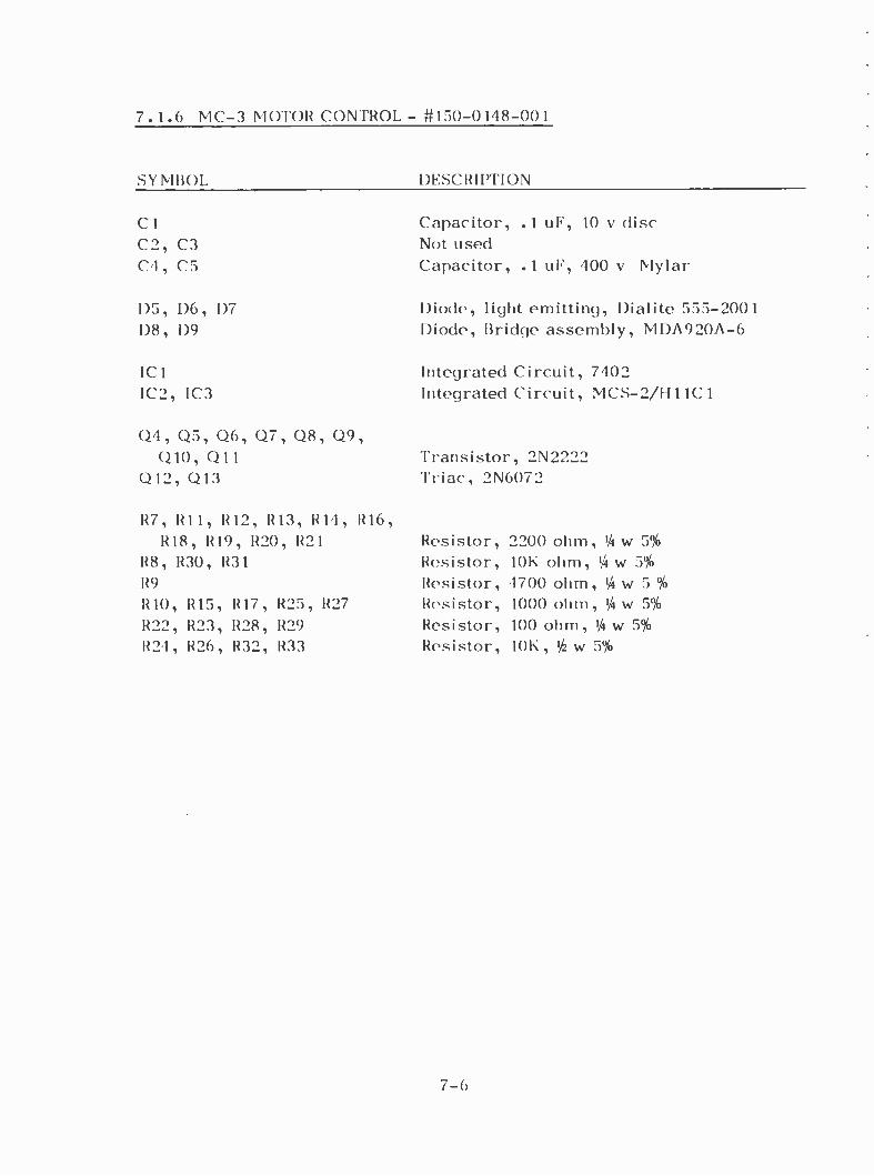
7.1.6 MC -3 MOTOR CONTROL - #150 -0148 -001
SYMBOL DESCRIPTION
Cl C2, C3 C4, C5
D5, D6, D7 D8, D9
IC1 IC2, 1C3
Q4, Q5, Q6, Q7, Q8, Q9, Q10, Q11
Q12, Q13
Capacitor, .1 uF, 10 y disc Not used Capacitor, .1 uF, 400 y Mylar
Diode, light emitting, I)ialite 555 -2001 Diode, Bridge assembly, MDA920A -6
Integrated Circuit, 7402 Integrated Circuit, MCS- 2/H11C1
Transistor, 2N2222 Triac, 2N6072
R7, RH, 1212, 1213, R14, R16, R18, R19, R20, R21 Resistor, 2200 ohm, 1,4 w 5%
128, R30, R31 Resistor, 10K ohm, lit w 5%
R9 Resistor, 4700 ohm, 1/4 w 5 %
R10, 1215, R17, R25, R27 Resistor, 1000 ohm, 1/4 w 5%
R22, R23, R28, 1229 Resistor, 100 ohm, 1/4 w 5%
R24, R26, R32, R33 Resistor, 10K, / w 5%
7 -6

6 ;; 7.1.7 INDEX SENSE AMPLIFIER SA -1 - #150 -0188 -001
SYMBOL I)F,SCRIPTION
Cl Capacitor, disc, .1 uF, 10 v
C2 Cap. 15 W. Tant. Dl Diode, light emitting, FLV -110/
XC554 -6 /Dialite 555 -2001
Q 1, Q2 Transistor, 2N2222 Q3 Reflective Sensor, SPX - 1404 -2
Rl, R5 Resistor, 100, /a w 5%
R2 Resistor, 56K, 1/4 w 5%
R3 Resistor, 10K, 1/4 w 5%
R4 Resistor, 1000, 1/4 w 5%
7 -7

7.2 MAIN CHASSIS ASSENIBI l
7.2.1 SG -1 SOLENOID GATE ASSEMBLY - P155-0006-002
SYSTEM DESCRIPTION
Circuit board Socket, IC, 14 Pin DIP
Cl Capacitor, Electro., 30/50 uF, 150 y C2 Capacitor, oil, 1.5 uF, 220 v
(See note below concerning C2)
ICI Integrated Circuit, MCS -2 /I1 1 1C 1/I 111C2
Q1 Transistor, 2N6240 or S2060D
R1, R4 Resistor, 10K, 1/i2. w 5;6
R2 Resistor, 22K, 1/1w 5%
R3 Resistor, 2200, 1,4 w 5%
R5 Resistor, 200, 10 w 116 Resistor, 12, 2 w, BWH
NOTE: On Tape Cartridge Machines using 50 Hz capstan motors, C2 becomes a 1.8 uF oil filled capacitor. On some units, this 1.8 uF unit may be mounted off of the SG -1 board.
7-8

7.2.2 RF -1 RECTIFIER FILTER - #155 -0004 -001
SYMBOL DESCRIPTION
D1
R1
Rectifier, Bridge, MDA920A -6
Resistor, 10K, 1 w 5%
7.2.3 CHASSIS MOUNTED PARTS
Cl
F1
F2
FL1
Q1
*T1
T2 T3
Power switch Manual switch Stop button Stop light Start button Start light Tray button Rotate button In Limit Switch Out Limit Switch Cartridge switch Random /Sequence Switch Drum Motor Shift Motor Capacitors, Control Motors
Capacitor, 5600 uF, 25 v
Fuse, 1 amp, 3AG Fuse, 1 amp
RF line filter, CORCOM 2K2 / RFI
Regulator, 5 v, LM309K
Transformer, Power, M873A /B Transformer, Output, M956 / M975 Transformer, Output, M956, Stereo only
8111011, Microswitch, Red 8111011, Microswitch, Blue LUS -08 -1, Yellow 7377, 5 volt Bi -Pin LUS -05 -1, White 7377 5 volt Bi -Pin LUS -03 -1, Green LUS -03 -1, Green BA 2RV22T Microswitch BA 2RV22T Microswitch DT2RV22A 7 Microswitch/ 101SN 11 Microswitch 8A 1011 Microswitch URM6P4 - W. 6G - 150FI Gear URM6P4 - W. 6G - 60H Gear 2 MFD - Oil
*T1 is M874 on 240/120 v models For 805A transport parts, see P. 6 -11 For 805A heads, see Page 6 -14
7 -9

CL-1 COMPARATOR/LATCH PCFi ( 350-RSP. ) 150-02? (-001
SYMBOL DESCRIPTION
Rl, R2, R3, R4, R5, R6, R7,
R8, R9, R10, R11, R12,
R13, R14 Resistor, 2200, i watt, 5%
R15, R21 Resistor, 4700, 4 watt, 5% R16 Resistor, 10K, 4 watt, 5%
R17, R20 Resistor, 47K, 4 watt, 5%
R18, R19 Resistor, 22K, 4 watt, 5%
R22 Resistor, 1000, 4 watt, 5%
Cl, C2, C3
C4, C5 Capacitor, Disc. .1 uF, 10v
Capacitor, Disc. .01 uF, 10V
Dl, D2, D3, D4, D5, D6 Diode, 1N914
IC1,
IC2,
IC3
Ql,
Q3
IC4 Integrated Circuit, 74175 IC5 Integrated Circuit, 7486
Q2, Q4
Integrated
Transistor,
Transistor,
Circuit,
2N2222
2N2907
7400
7 -10

,D -4- -I +1 ae }- Z- ad
1.
ct
r
t
(*)
v
m
h '
h v
+
.L.
o o;
-r
J 22
7 -11
á
o
U
o
N r
o N

o ._
t
3
5
á
7 -12

F w N o w ú x o o o
SID
6»
D/v
£D
Kura F/è
) Z.7.r
a ZU
b o -c- Q
6Zò'
9Zà'
d 5---D
9 E
a
i --r
GERM
C cv Z-5) P
iay 9li
-E) y 8/ë
-{ oZa' l- 0s
V 1='
L1
^ 4 v v
69
1",
O J
J
n
..
;T.) /Cd'
n M
T
ety
OZJ
r
:
ó
Ñ.
7 -13 J

oo
o
N i a t4
1, z
i If
o i o
4
CUO
fl
S
SiAI-NA/Sr.
A
)1
4 40 4-
f a © ñ n {a
-Il V
Ñ y1 r 1_2 1 -y/1/r
N
7 -14
n y o

o-
m
T
C-
v 1),
Ú -
cJ
N
,-.---- N ,( a$ ' er .
+ M i- Q N h u t v
yW
Q
7 -15

I
u U
T u
- il
tfl
lp
1
7 -11
0
y.:
O
i b t N tb o t
y r ti r p H


"-I
4}
{± 0 `-1- ', Ì_
oo
T
>>j,
V V, --I 1F-
O 'ILL-NI- (It
OV
7 -19
o r M
i
O
41 N O
7 -20

1..
á
1 s
fr T
1 ó
CY
V
62e-
N l)
1
I
., - 9110}-
Co CO
7 -21
0
4
i

W ^
.M1 - . . n . . n ( s
o
t
W o
IP
k,
A W
í' \
7 -22
A

cL % ,4 cJ
-V-'-- o U C7 0 c
,,r1- -a d 1 --i--
cf
1
r C (i} ` -cJ i
O 9
1
Oki -[sz r t
o t -1 01; o
7 -23
J U N
w H
0
2
ó
n r

: o
o o
N o z r
'.) 3 O w 1-+ m
o 1 m
ti
r m
o
z to
w O
7 -24

n
o
C
o
U
Jo -o
[e
.1 o
mo
c)o
C-] o
=o
LL O
o
c0o
7 -25

(n U fu
iZ.
t -. (u l,. ri
ct
t
C) V) 0
1
M , I (') O rv
W N -- I 1 1
DA -i x O mO m
m
o 3 o z f =. a
( I
cb
° j N.
0
ú 4
v CD
ó _
N W
v)
C>
o
o
rn r- ri
o N
7 -26

C3
rn U
e U
u
..
o c 1n w
si
--FOI .p --
CJ
7 -27

J
®®
rv pY N N1 4J
VV\/VN-' o n
rc
J_ J N J-
T
0 m 0¡ h -4 to
L7 o, , P o ?zsZr?a? ?a?z
a-
01 n Q
N t rc) O In
(3)
N n
to If)
N M /AAAAr __ _ _ Yrv-i
Of R I I IN
b
CO
L h
J U z
ó
ñ
o
a
'
4 ó
w
w
o J
Z
O O -J
N
a U
N 7 !V NMi
K N'
I I
h
ÑN ÑN It(-+ 12N
V '-^ ̂ -v_A wAA A
Ú o C,
co -0
nn ( V ICXX)\
ea C7)
CC f
M
in .1- u) \o r-. [101. N
7 - 28

7.1.3 LC -1 LOGIC CONTROL - #150 -0144 -001
SYMBOL DESCRIPTION
Cl, C2, C6, C7, C8, C9, C10, C11, C12, C15, C17 Capacitor, disc, .1 uF, 10 v
C5, C14 Capacitor, disc, .01 uF, 10 y C3 Capacitor, disc, 470 pF, lk y C4, C13 Capacitor, tantalum, 8.2 uF, 6 y 10% C16 Capacitor, tantalum, 2.2 uF, 20 y
D1, D2, D3 Diode, 1N914
IC 1 Integrated Circuit, 7400 IC2 Integrated Circuit, 7410 IC3 Integrated Circuit, 7402 IC4, IC5 Integrated Circuit, NE555V
QI, Q2, Q3, Q4, Q5, Q6 Transistor, 2N2222
R1 Not used R2, R6, R7, R13, R20
R28, R29, R31 Resistor, 1000, '/aw, 5% R3, R25 Resistor, 10K, 3/4w, 5% R4, R5, R14, R15, R18,
R19, R23, R24 Resistor, 2200, Viw, 5% R8 Resistor, 150, 3/4w, 5% R9, R11, R21 Resistor, 15, 4w, 5% R10, R12, R22 Resistor, 220, 3w, 5% R16, R27 Resistor, 220K, 3/4w, 5% R26 Resistor, 3300, 1/4w, 5% R30 Resistor, 470, 14w, 5%
7 -3

a
T-L
8
o
o
f-' n
w
aQ oa --n
,0
o
N ,c
FuI

m
t ,Nb 'bb g .,
QS ri
61,0 c--T) o
8h0 ©L N0
9 b N.4 0 ,Sbd ©
bb',
( I)
( I)
_ . n _ a C hO
0 Ib0
( I)
( I) á = n to r
6£O c_-_-1)s£O
tCOc r
9F0
N m
o z
v
s
7
o
7 - 29
y

J J W
~ W Q z z óá °¢
ce
F
I:
m cr
¢
o o
é O I K ló o
O
O O
0 ÿ O Q O O
O O
O O O
o O .1
I á
O.' 1 `
~H° n u
T >
z 2
O:
a
J
I i ó
w
¢ H
N W J
IM WK S -
w F U
á u-1O O ~
F0 In~F p U O
V Ñ Z
ám;ó cc w_ Jrnte-TO
L7)11-
) J Q7pl".O p
¢V) 6OmÑ l n ¢
J z w z ¢ O m oWÓ0óz00=7 Z Ñ Z m z z D- ¢wpwN3íwc Opt-2W W
V)?QOJw2 J V)QW WlnJU_ -_ W iW 0 0 0 á Ú o z _ N Ni R
on A i O0 0
X z
A
O
O
á Z a
Q ~ J
m Q z W
F
z U
o oO meelmo
á
o
11
8 cr cc o 0
i U
W Q o
O z w J O rn
z 2 ~O 3 áóá
V) 0
o n
Q z0 U °j á ZN W
O O?
2 Ñ
OJ J o
Zm Q
r OJ a
117 J
WV) V)
O
LL Q ¢
" Oo t w rfi ¢ W
° ~ -w ON V J#
>7 IC7á
In N- CO av
Zr- f` z
O 6,°°5- Q Zo
r0
Z /¡o VI re ¡\ry
L-1
_01
xvI- I
U ILI ZI 1- W O ;WCI 0 }I QI Úx
I
!1 f I
IE
- Oil-- --0 I
O I
O 01 1
11
O/ô l te
O rn
6tt #
z Z 1.! m
N
II[ > Wo
o-
3
.
á á 1-00 =f.)p WO< 004 W¢W -¢W Ja2 Sa2
RIIMM ammO O n Ñ
n w U r.
p W.1 7 W U S
O z
O.0O.0 O..OOOOOÓO
a
r.3_ °+
¢ O
w Y z oz 0 wo
a
0 0 O O
1
O S O O N-o o°L
¢
Fr.
AO; U
o='-
-
O
rñ M m COCO ®-
2 2 4-
U Q >

¢ m
Ir
I?-
o ^I
O o o
i
J 2 J W rw < ZZ H[J °á o¢H
á
z 2
a
O z o
J
U a h
o
o o
o
co-11' I 0
o-0
h
Im00 1
1D ID I.-
¢. r
U < W
O a 7 F
-O-o-O-p-O- m T
l
ii
-o. O INNER 1116
rn N
n
ñ
O
o
f m - N
p Ñ OroO m 01
O ¢
3
a U
MIN
a
eir CO
m
r Ñ N ° ' 0 . 4 . 1 .
0 0 m N M -
n 01 o o
W
O ó z
Ó N
w
H
J 0
r NJ V1W
¢ W
OJ ra o°
¢ w
W
O
m 1
O o O
-O o¡I 1
I r o o w ., o.
z_ î Z ¢ O a U O N
o o
I-{11 o o ôl
O N
®
N I-
1
Q Q = ¢ r O SUO
LL Da (DO< Já2 MOW
a. r D o
D e)\ n A o z W
D ! \
I
O W OW U
o Z r
W
a Z W
o-
J
o J
...,O-o.O-o-o-i
U J
o.
O O
O
T_
rr O O
ÚZ O pT -
¢
¢
O
o>
0 I-- " ' é i .M,.,
a >


