Warranty and Service Powermatic® warrants every product it sells against manufacturers’ defects. If one of our tools needs service or repair, please contact Technical Service by calling 1-800-274-6846, 8AM to 5PM CST, Monday through Friday.
Warranty Period The general warranty lasts for the time period specified in the literature included with your product or on the official Powermatic branded website.
Powermatic products carry a limited warranty which varies in duration based upon the product. (See chart below)
Accessories carry a limited warranty of one year from the date of receipt. Consumable items are defined as expendable parts or accessories expected to become inoperable within a
reasonable amount of use and are covered by a 90 day limited warranty against manufacturer’s defects.
Who is Covered This warranty covers only the initial purchaser of the product from the date of delivery.
What is Covered This warranty covers any defects in workmanship or materials subject to the limitations stated below. This warranty does not cover failures due directly or indirectly to misuse, abuse, negligence or accidents, normal wear-and-tear, improper repair, alterations or lack of maintenance. Powermatic woodworking machinery is designed to be used with Wood. Use of these machines in the processing of metal, plastics, or other materials outside recommended guidelines may void the warranty. The exceptions are acrylics and other natural items that are made specifically for wood turning.
Warranty Limitations Woodworking products with a Five Year Warranty that are used for commercial or industrial purposes default to a Two Year Warranty. Please contact Technical Service at 1-800-274-6846 for further clarification.
How to Get Technical Support Please contact Technical Service by calling 1-800-274-6846. Please note that you will be asked to provide proof of initial purchase when calling. If a product requires further inspection, the Technical Service representative will explain and assist with any additional action needed. Powermatic has Authorized Service Centers located throughout the United States. For the name of an Authorized Service Center in your area call 1-800-274-6846 or use the Service Center Locator on the Powermatic website.
More Information Powermatic is constantly adding new products. For complete, up-to-date product information, check with your local distributor or visit the Powermatic website.
How State Law Applies This warranty gives you specific legal rights, subject to applicable state law.
Limitations on This Warranty POWERMATIC LIMITS ALL IMPLIED WARRANTIES TO THE PERIOD OF THE LIMITED WARRANTY FOR EACH PRODUCT. EXCEPT AS STATED HEREIN, ANY IMPLIED WARRANTIES OF MERCHANTABILITY AND FITNESS FOR A PARTICULAR PURPOSE ARE EXCLUDED. SOME STATES DO NOT ALLOW LIMITATIONS ON HOW LONG AN IMPLIED WARRANTY LASTS, SO THE ABOVE LIMITATION MAY NOT APPLY TO YOU. POWERMATIC SHALL IN NO EVENT BE LIABLE FOR DEATH, INJURIES TO PERSONS OR PROPERTY, OR FOR INCIDENTAL, CONTINGENT, SPECIAL, OR CONSEQUENTIAL DAMAGES ARISING FROM THE USE OF OUR PRODUCTS. SOME STATES DO NOT ALLOW THE EXCLUSION OR LIMITATION OF INCIDENTAL OR CONSEQUENTIAL DAMAGES, SO THE ABOVE LIMITATION OR EXCLUSION MAY NOT APPLY TO YOU. Powermatic sells through distributors only. The specifications listed in Powermatic printed materials and on the official Powermatic website are given as general information and are not binding. Powermatic reserves the right to effect at any time, without prior notice, those alterations to parts, fittings, and accessory equipment which they may deem necessary for any reason whatsoever.
Product Listing with Warranty Period
90 Days – Parts; Consumable items 1 Year – Motors, Machine Accessories 2 Year – Woodworking Machinery used for industrial or commercial purposes 5 Year – Woodworking Machinery
NOTE: Powermatic is a division of JPW Industries, Inc. References in this document to Powermatic also apply to JPW Industries, Inc., or any of its successors in interest to the Powermatic brand.
3
Table of Contents
Warranty and Service .................................................................................................................................... 2 Table of Contents .......................................................................................................................................... 3 Warnings ....................................................................................................................................................... 4 Introduction ................................................................................................................................................... 6 Specifications ................................................................................................................................................ 6 Unpacking ..................................................................................................................................................... 7
Contents of the Mortiser Carton ................................................................................................................ 7 Contents of the Stand Carton .................................................................................................................... 7
Electrical Connections ................................................................................................................................... 8 Grounding Instructions .............................................................................................................................. 8 Converting from 115 to 230 Volt ................................................................................................................ 9 Extension Cords ........................................................................................................................................ 9
Assembly ..................................................................................................................................................... 10 Securing Machine to Stand ..................................................................................................................... 10 Wooden Table ......................................................................................................................................... 10 Operating Handle .................................................................................................................................... 10 Installing Chisel and Bit ........................................................................................................................... 11 Work Stop ................................................................................................................................................ 11
90 Chisel to Worktable Calibration ......................................................................................................... 13 Chuck Extension Adaptor ........................................................................................................................ 13 Depth Stop Rod Adjustment .................................................................................................................... 14 Table Position .......................................................................................................................................... 14
Forward/Backward Table Movement ................................................................................................... 14 Lateral Table Movement ...................................................................................................................... 14 Table Tilt Control .................................................................................................................................. 14
General .................................................................................................................................................... 16 Sharpening Chisel and Bit ....................................................................................................................... 16
Bit ......................................................................................................................................................... 16 Chisel ................................................................................................................................................... 17
Optional Accessories .................................................................................................................................. 17 Replacement Parts ...................................................................................................................................... 17
719T Mortiser Assembly .......................................................................................................................... 18 719T Mortiser Parts List .......................................................................................................................... 19 719T Mortiser Stand Parts List ................................................................................................................ 22 719T Mortiser Stand Assembly ............................................................................................................... 22 Optional Accessories ............................................................................................................................... 23
Dimensions for 719T with premium chisels mounted ................................................................................. 24
4
Warnings
1. Read and understand the entire owner’s manual before attempting assembly or operation.
2. Read and understand the warnings posted on the machine and in this manual. Failure to comply with all of these warnings may cause serious injury.
3. Replace the warning labels if they become obscured or removed.
4. This mortiser is designed and intended for use by properly trained and experienced personnel only. If you are not familiar with the proper and safe operation of a mortiser, do not use until proper training and knowledge have been obtained.
5. Do not use this mortiser for other than its intended use. If used for other purposes, Powermatic disclaims any real or implied warranty and holds itself harmless from any injury that may result from that use.
6. Always wear approved safety glasses/face shields while using this mortiser. Everyday eyeglasses only have impact resistant lenses; they are NOT safety glasses. Also use a dust mask if cutting operation is dusty.
7. Before operating this mortiser, remove tie, rings, watches and other jewelry, and roll sleeves up past the elbows. Secure all loose clothing and confine long hair. Non-slip footwear or anti-skid floor strips are recommended. Do not wear gloves.
8. Wear ear protectors (plugs or muffs) during extended periods of operation.
9. Do not operate this machine while tired or under the influence of drugs, alcohol or any medication.
10. Make certain the switch is in the OFF position before connecting the machine to the power supply.
11. Make certain the machine is properly grounded.
12. Make all machine adjustments or maintenance with the machine unplugged from the power source.
13. Remove adjusting keys and wrenches. Form a habit of checking to see that keys and adjusting wrenches are removed from the machine before turning it on.
14. Keep safety guards in place at all times when the machine is in use. If removed for maintenance purposes, use extreme caution and replace the guards immediately after maintenance is complete.
15. Make sure the mortiser is firmly secured to the stand before use.
16. Check damaged parts. Before further use of the machine, a guard or other part that is damaged should be carefully checked to determine that it will operate properly and perform its intended function. Check for alignment of moving parts, binding of moving parts, breakage of parts, mounting and any other conditions that may affect its operation. A guard or other part that is damaged should be properly repaired or replaced.
17. Provide for adequate space surrounding work area and non-glare, overhead lighting.
18. Keep the floor around the machine clean and free of scrap material, oil and grease.
19. Keep visitors a safe distance from the work area. Keep children away.
20. Make your workshop child proof with padlocks, master switches or by removing starter keys.
21. Give your work undivided attention. Looking around, carrying on a conversation and “horse-play” are careless acts that can result in serious injury.
22. Maintain a balanced stance at all times so that you do not fall or lean against the chisel and drill bits or other moving parts. Do not overreach or use excessive force to perform any machine operation.
23. Use the right tool at the correct speed and feed rate. Do not force a tool or attachment to do a job for which it was not designed. The right tool will do the job better and safer.
24. Use recommended accessories; improper accessories may be hazardous.
25. Do not use this tool in damp or wet locations.
5
26. Maintain tools with care. Keep chisel and drill bits sharp and clean for the best and safest performance. Follow instructions for lubricating and changing accessories.
27. Make sure the work piece is securely attached or clamped to the table. Do not cut mortises freehand.
28. Turn off the machine before cleaning. Use a brush or compressed air to remove chips or debris — do not use your hands.
29. Do not stand on the machine. Serious injury could occur if the machine tips over.
30. Never leave the machine running unattended. Turn the power off and do not leave the machine until it comes to a complete stop.
31. Remove loose items and unnecessary work pieces from the area before starting the machine.
Familiarize yourself with the following safety notices used in this manual:
This means that if precautions are not heeded, it may result in minor injury and/or possible machine damage.
This means that if precautions are not heeded, it may result in serious injury or possibly even death.
- - SAVE THESE INSTRUCTIONS - -
WARNING: Drilling, sawing, sanding or machining wood products generates wood dust and other substances known to the State of California to cause cancer. Avoid inhaling dust generated from wood products or use a dust mask or other safeguards for personal protection.
Wood products emit chemicals known to the State of California to cause birth defects or other reproductive harm. For more information go to http://www.p65warnings.ca.gov/wood.
WARNING: This product can expose you to chemicals including lead which is known to the State of California to cause cancer and birth defects or other reproductive harm. For more information go to http://www.p65warnings.ca.gov.
6
Introduction This manual is provided by Powermatic covering the safe operation and maintenance procedures for a Powermatic Model 719T Tilting Table Hollow Chisel Mortiser. This manual contains instructions on installation, safety precautions, general operating procedures, maintenance instructions and parts breakdown. This machine has been designed and constructed to provide consistent, long-term operation if used in accordance to instructions set forth in this manual. If there are any questions or comments, please contact either your local supplier or Powermatic. Powermatic can also be reached at our web site: www.powermatic.com.
Specifications Model No. ................................................................................................................................................ 719T Stock No. ......................................................................................................................................... 1791264K Stock No – Mortiser only ................................................................................................................. 2474002T Stock No – Stand only ..................................................................................................................... 6294235T Motor ........................................................................ TEFC, 1 HP, 1 PH, 115V/230V (Prewired 115V), 60Hz Spindle speed ................................................................................................................................ 1725 RPM Table tilt ............................................................................................................................................ 0 to 35 Chisel capacity ..................................................................................................................................1/4" to 1" Chisel shank diameters ........................................................................................................ 5/8", 3/4", 1-1/8" Maximum chisel stroke ......................................................................................................................... 10-3/4" Maximum head stroke .................................................................................................................................. 6" Maximum chisel center to fence distance .................................................................................................... 4" Chuck capacity .......................................................................................................................................... 1/2" Bushing size .......................................................................................................................... 5/8", 3/4", 1-1/8" Longitudinal table travel ....................................................................................................................... 15-1/2" Cross table travel ......................................................................................................................................... 4" Table size ..................................................................................................................................... 7" x 20-1/4" Fence size .............................................................................................................................. 4-1/2" x 20-1/4" Base size ........................................................................................................................................... 14" x 16" Overall dimensions assembled ........................................................................ 21-1/4" L x 21-5/8" W x 74" H Weight - Mortiser ......................................................................... Net weight 230 lbs., Gross weight 242 lbs. Weight - Stand ................................................................................. Net weight 46 lbs., Gross weight 50 lbs.
The above specifications were current at the time this manual was published, but because of our policy of continuous improvement, Powermatic reserves the right to change specifications at any time and without prior notice, without incurring obligations.
7
Unpacking Remove mortiser and stand from the shipping cartons. Report any damage immediately to your distributor and shipping agent. Do not discard any shipping material until the mortiser is assembled and running properly.
Compare the contents of your container with the following parts list and Figure 1 to make sure all parts are intact. Missing parts, if any, should be reported to your distributor. Read this instruction manual thoroughly to familiarize yourself with the correct assembly and maintenance procedures and proper safety precautions.
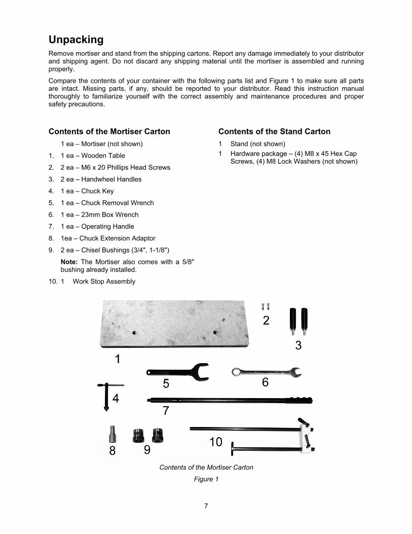
Contents of the Mortiser Carton
1 ea – Mortiser (not shown)
1. 1 ea – Wooden Table
2. 2 ea – M6 x 20 Phillips Head Screws
3. 2 ea – Handwheel Handles
4. 1 ea – Chuck Key
5. 1 ea – Chuck Removal Wrench
6. 1 ea – 23mm Box Wrench
7. 1 ea – Operating Handle
8. 1ea – Chuck Extension Adaptor
9. 2 ea – Chisel Bushings (3/4", 1-1/8")
Note: The Mortiser also comes with a 5/8" bushing already installed.
10. 1 Work Stop Assembly
Contents of the Stand Carton
1 Stand (not shown)
1 Hardware package – (4) M8 x 45 Hex Cap Screws, (4) M8 Lock Washers (not shown)
Contents of the Mortiser Carton
Figure 1
8
Electrical Connections A separate electrical circuit should be used for your machines. This circuit should not be less than #12 wire and should be protected with a 20 Amp time lag fuse. If an extension cord is used, use only 3-wire extension cords which have 3-prong grounding type plugs and matching receptacle, which will accept the machine’s plug. Before connecting the machine to the power line, make sure the switch is in the Off position and be sure that the electric current is of the same characteristics as indicated on the machine. All line connections should make good contact. Running on low voltage will damage the machine.
Grounding Instructions
Electrical connections must be made by a qualified electrician in compliance with all relevant codes. This machine must be properly grounded to help prevent electrical shock and possible fatal injury.
1. All grounded, cord-connected tools:
In the event of a malfunction or breakdown, grounding provides a path of least resistance for electric current to reduce the risk of electric shock. This tool is equipped with an electric cord having an equipment-grounding conductor and a grounding plug. The plug must be plugged into a matching outlet that is properly installed and grounded in accordance with all local codes and ordinances.
Do not modify the plug provided - if it will not fit the outlet, have the proper outlet installed by a qualified electrician.
Improper connection of the equipment-grounding conductor can result in a risk of electric shock. The conductor with insulation having an outer surface that is green with or without yellow stripes is the equipment-grounding conductor. If repair or replacement of the electric cord or plug is necessary, do not connect the equipment-grounding conductor to a live terminal.
Check with a qualified electrician or service personnel if the grounding instructions are not completely understood, or if in doubt as to whether the tool is properly grounded.
Use only 3-wire extension cords that have 3-prong grounding plugs and 3 pole receptacles that accept the tool's plug.
Repair or replace damaged or worn cord immediately.
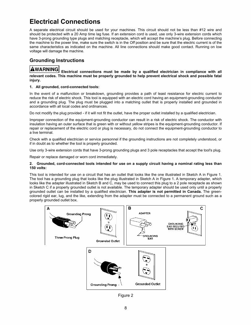
2. Grounded, cord-connected tools intended for use on a supply circuit having a nominal rating less than 150 volts:
This tool is intended for use on a circuit that has an outlet that looks like the one illustrated in Sketch A in Figure 1. The tool has a grounding plug that looks like the plug illustrated in Sketch A in Figure 1. A temporary adapter, which looks like the adapter illustrated in Sketch B and C, may be used to connect this plug to a 2 pole receptacle as shown in Sketch C if a properly grounded outlet is not available. The temporary adapter should be used only until a properly grounded outlet can be installed by a qualified electrician. This adapter is not permitted in Canada. The green-colored rigid ear, lug, and the like, extending from the adapter must be connected to a permanent ground such as a properly grounded outlet box.
Figure 2
9
3. Grounded, cord- connected tools intended for use on a supply circuit having a nominal rating between 150 - 250 volts, inclusive.
This tool is intended for use on a circuit that has an outlet that looks like the one illustrated in Sketch D in Figure 1. The tool has a grounding plug that looks like the plug illustrated in Sketch D in Figure 1. Make sure the tool is connected to an outlet having the same configuration as the plug. No adapter is available or should be used with this tool. If the tool must be reconnected for use on a different type of electric circuit, the reconnection should be made by qualified service personnel; and after reconnection, the tool should comply with all local codes and ordinances.
4. Permanently connected tools:
This tool should be connected to a grounded metal permanent wiring system; or to a system having an equipment-grounding conductor.
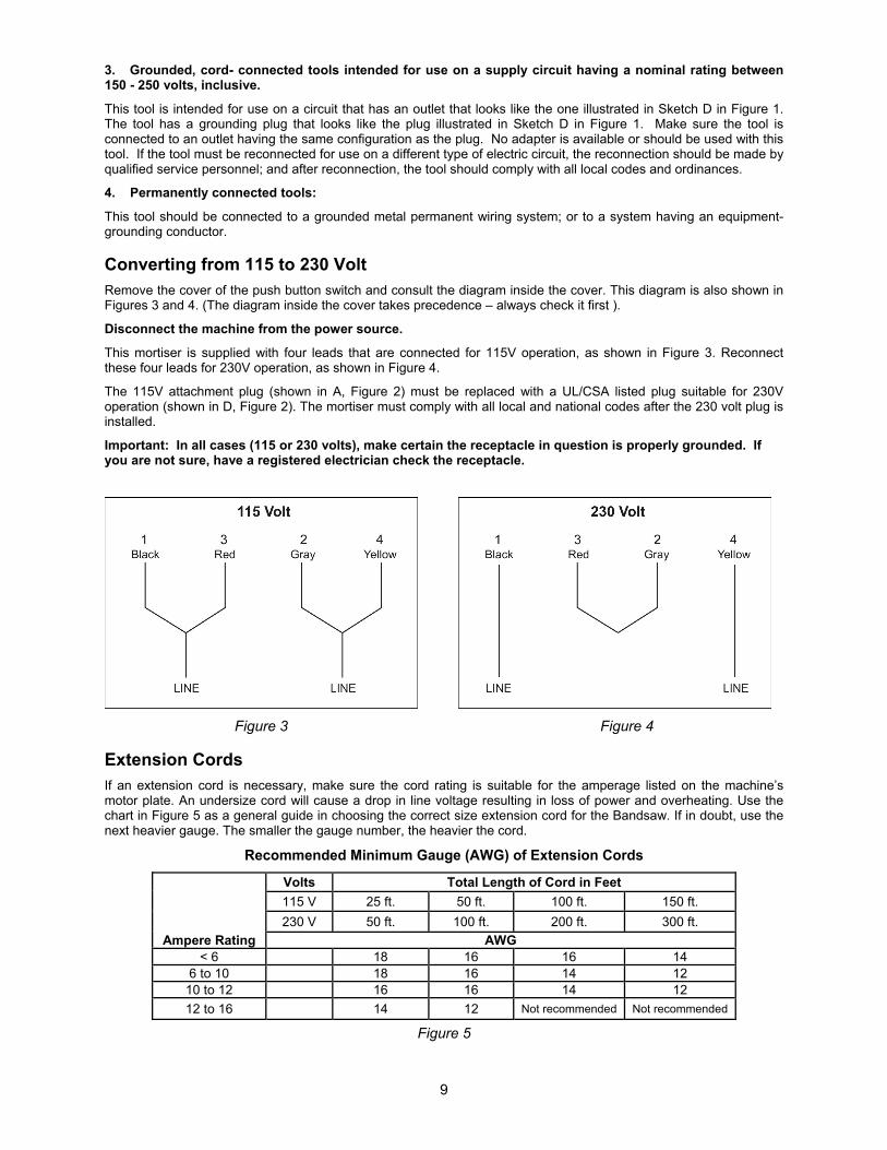
Converting from 115 to 230 Volt Remove the cover of the push button switch and consult the diagram inside the cover. This diagram is also shown in Figures 3 and 4. (The diagram inside the cover takes precedence – always check it first ).
Disconnect the machine from the power source.
This mortiser is supplied with four leads that are connected for 115V operation, as shown in Figure 3. Reconnect these four leads for 230V operation, as shown in Figure 4.
The 115V attachment plug (shown in A, Figure 2) must be replaced with a UL/CSA listed plug suitable for 230V operation (shown in D, Figure 2). The mortiser must comply with all local and national codes after the 230 volt plug is installed.
Important: In all cases (115 or 230 volts), make certain the receptacle in question is properly grounded. If you are not sure, have a registered electrician check the receptacle.
Figure 3 Figure 4
Extension Cords
If an extension cord is necessary, make sure the cord rating is suitable for the amperage listed on the machine’s motor plate. An undersize cord will cause a drop in line voltage resulting in loss of power and overheating. Use the chart in Figure 5 as a general guide in choosing the correct size extension cord for the Bandsaw. If in doubt, use the next heavier gauge. The smaller the gauge number, the heavier the cord.
Recommended Minimum Gauge (AWG) of Extension Cords
Ampere Rating
Volts Total Length of Cord in Feet
115 V 25 ft. 50 ft. 100 ft. 150 ft.
230 V 50 ft. 100 ft. 200 ft. 300 ft.
AWG < 6 18 16 16 14
6 to 10 18 16 14 12 10 to 12 16 16 14 12
12 to 16 14 12 Not recommended Not recommended
Figure 5
10
Assembly
Do not connect the machine to power source until completely assembled. Read and understand the entire manual.
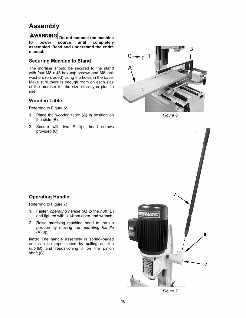
Securing Machine to Stand
The mortiser should be secured to the stand with four M8 x 45 hex cap screws and M8 lock washers (provided) using the holes in the base. Make sure there is enough room on each side of the mortiser for the size stock you plan to use.
Wooden Table
Referring to Figure 6:
1. Place the wooden table (A) in position on the slide (B).
2. Secure with two Phillips head screws provided (C).
Operating Handle
Referring to Figure 7:
1. Fasten operating handle (A) to the hub (B) and tighten with a 14mm open-end wrench.
2. Raise mortising machine head to the up position by moving the operating handle (A) up.
Note: The handle assembly is spring-loaded and can be repositioned by pulling out the hub (B) and repositioning it on the pinion shaft (C).
Figure 6
Figure 7
11
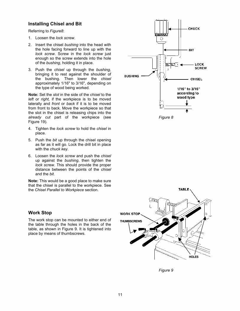
Installing Chisel and Bit
Referring to Figure8:
1. Loosen the lock screw.
2. Insert the chisel bushing into the head with the hole facing forward to line up with the lock screw. Screw in the lock screw just enough so the screw extends into the hole of the bushing, holding it in place.
3. Push the chisel up through the bushing, bringing it to rest against the shoulder of the bushing. Then lower the chisel approximately 1/16" to 3/16", depending on the type of wood being worked.
Note: Set the slot in the side of the chisel to the left or right, if the workpiece is to be moved laterally and front or back if it is to be moved from front to back. Move the workpiece so that the slot in the chisel is releasing chips into the already cut part of the workpiece (see Figure 19).
4. Tighten the lock screw to hold the chisel in place.
5. Push the bit up through the chisel opening as far as it will go. Lock the drill bit in place with the chuck key.
6. Loosen the lock screw and push the chisel up against the bushing, then tighten the lock screw. This should provide the proper distance between the points of the chisel and the bit.
Note: This would be a good place to make sure that the chisel is parallel to the workpiece. See the Chisel Parallel to Workpiece section.
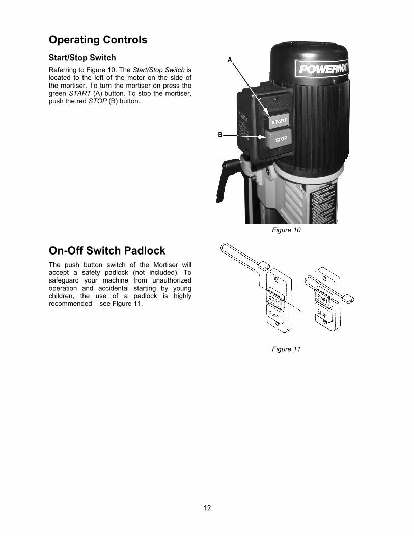
Work Stop
The work stop can be mounted to either end of the table through the holes in the back of the table, as shown in Figure 9. It is tightened into place by means of thumbscrews.
Figure 8
THUMBSCREWS
HOLES
Figure 9
12
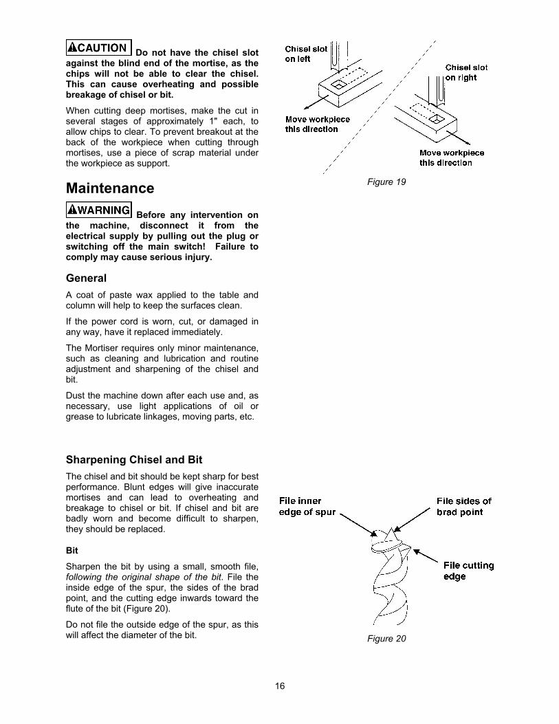
Operating Controls
Start/Stop Switch
Referring to Figure 10: The Start/Stop Switch is located to the left of the motor on the side of the mortiser. To turn the mortiser on press the green START (A) button. To stop the mortiser, push the red STOP (B) button.
On-Off Switch Padlock The push button switch of the Mortiser will accept a safety padlock (not included). To safeguard your machine from unauthorized operation and accidental starting by young children, the use of a padlock is highly recommended – see Figure 11.
Figure 10
Figure 11
13
Adjustments
90 Chisel to Worktable Calibration
Referring to Figure 12:
Place a square (E) so it rests against the worktable (B) and chisel (A). If the chisel to table angle is 90, no calibration is necessary.
If calibration is required:
1. Loosen the bolt (C) that allows the tilting base to pivot.
The tilting base is heavy. If raised, take extra precaution not to let it drop on hands or fingers. Injury can result.
2. Adjust the adjustment screws (F) until the chisel to table angle is 90. Calibration is then complete.
3. Retighten the bolt (C).
Upon completion, make sure that the pointer points to 0. Calibrate if necessary.
Chuck Extension Adaptor
The provided Chuck Extension Adaptor (C) is intended to lower the chuck for use with after-market chisels (chisels other than the POWERMATIC brand) that may require a spacer due to varying lengths in shanks.
To install the adaptor, first remove the chisel and bit (see the Installing Chisel and Bit section). Then, referring to Figure 13:
1. Loosen the lock screw (E) enough to remove the chisel bushing (F).
2. Remove the chisel bushing (F). This is necessary to provide enough clearance when installing the chuck and extension adaptor.
3. Unscrew the chuck release nut (A) counterclockwise with the wrench provided to force the chuck (D) off the shaft (B).
It may be necessary to hold the shaft stationary while turning the nut. This can be done by inserting the chuck key handle into the hole in the chuck and allowing it to wedge against the edge of the headstock.
4. When the chuck is off, return the chuck release nut (A) to its original position on the shaft (B).
5. Push the adaptor (C) into the chuck (D). Then push this assembly onto the motor shaft (B).
Figure 12
Figure 13
14
6. Reinstall the chisel bushing (F) and secure it loosely with the lock screw (E).
7. Reinstall the chisel and bit (refer to the Installing Chisel and Bit section).
Depth Stop Rod Adjustment
Referring to Figure 14:
A depth stop rod (A) is provided to limit the depth of the chisel. To adjust:
1. Loosen lock lever (B) and lower the depth stop rod (A) until it comes to rest on top of the column stop (C).
2. With the operating handle (see Figure 2) lower the head (E) until the chisel (D) is at the desired depth.
3. The depth stop rod (A) should still be resting on top of the column stop (C).
4. Tighten the lock lever (B).
Table Position
The 719T Mortiser is equipped with two handwheels for table (E, Fig. 15) positioning. In addition, the table can be tilted up to 35 for angle mortising.
Forward/Backward Table Movement
1. Loosen the wing screw on the right side of the middle base under the table.
2. Turn the handwheel (A, Fig. 15) to move the table the forward or backward.
3. Tighten the wing screw.
Lateral Table Movement
1. Loosen the wing screw located on the back of the middle base located near the column.
2. Turn the handwheel (B, Fig. 15) to move the table to the right or left.
3. Tighten the wing screw.
Table Tilt Control
The tilt table is heavy. When raised, take extra precaution not to let it drop on hands or fingers. Injury can result.
1. Loosen bolt (C, Fig. 15) with the 23mm wrench provided.
2. Pivot the table to adjust the angle up to 35 using the scale (D) on the tilt bracket as a guide.
3. Tighten the bolt (C).
A
B
C D
E
Figure 14
Figure 15
15
Chisel Parallel to Workpiece
Referring to Figure 16:
The chisel can be adjusted parallel to the workpiece as follows:
1. With the left handwheel (A), move the table back far enough to insert the workpiece (B) between the chisel (D) and fence.
2. Loosen the lock screw (C). This will allow the chisel to rotate.
3. Bring the table forward with the handwheel (A) until the workpiece (B) rests against the back surface of the chisel (D), but do not force.
Further adjust the chisel by hand if needed.
4. Tighten the lock screw (C).
Operation 1. Set the depth stop (A, Fig. 17) to the
required depth of cut. Refer to the Depth Stop Rod Adjustment section.
5. Place workpiece on table (C, Fig. 18) and clamp it with the vise (A, Fig. 18). Use the left handwheel (D, Fig. 18) to move table forward or backward to suit the position of the mortise on the workpiece.
6. Adjust the table stops according to the length of cut required, then tighten the thumbscrews (B, Fig. 18).
Before turning the machine on, verify that the chuck key is not in the chuck.
7. Turn on the machine and feed the chisel and bit steadily into workpiece by pulling down the operating handle.
Note: The rate of feed must be fast enough to prevent burning at the tip of the bit, but not so fast as to cause the machine to slow or stall. The different rates of feed for different woods must be learned through experience.
8. After the first cut, the workpiece is moved along with the right handwheel (E. Fig. 18) for each successive cut. The direction of movement must allow the chips to clear freely. Move the workpiece so that the slot in the chisel is releasing chips into the already cut part of the workpiece (Figure 19).
Figure 16
C D
A B
Figure 17
A
B
C
D E
F
Figure 18
16
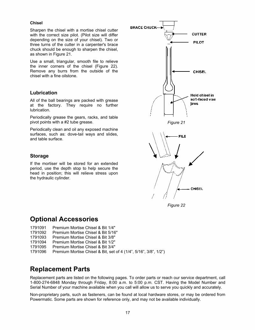
Do not have the chisel slot against the blind end of the mortise, as the chips will not be able to clear the chisel. This can cause overheating and possible breakage of chisel or bit.
When cutting deep mortises, make the cut in several stages of approximately 1" each, to allow chips to clear. To prevent breakout at the back of the workpiece when cutting through mortises, use a piece of scrap material under the workpiece as support.
Maintenance
Before any intervention on the machine, disconnect it from the electrical supply by pulling out the plug or switching off the main switch! Failure to comply may cause serious injury.
General
A coat of paste wax applied to the table and column will help to keep the surfaces clean.
If the power cord is worn, cut, or damaged in any way, have it replaced immediately.
The Mortiser requires only minor maintenance, such as cleaning and lubrication and routine adjustment and sharpening of the chisel and bit.
Dust the machine down after each use and, as necessary, use light applications of oil or grease to lubricate linkages, moving parts, etc.
Sharpening Chisel and Bit
The chisel and bit should be kept sharp for best performance. Blunt edges will give inaccurate mortises and can lead to overheating and breakage to chisel or bit. If chisel and bit are badly worn and become difficult to sharpen, they should be replaced.
Bit
Sharpen the bit by using a small, smooth file, following the original shape of the bit. File the inside edge of the spur, the sides of the brad point, and the cutting edge inwards toward the flute of the bit (Figure 20).
Do not file the outside edge of the spur, as this will affect the diameter of the bit.
Figure 19
Figure 20
17
Chisel
Sharpen the chisel with a mortise chisel cutter with the correct size pilot. (Pilot size will differ depending on the size of your chisel). Two or three turns of the cutter in a carpenter's brace chuck should be enough to sharpen the chisel, as shown in Figure 21.
Use a small, triangular, smooth file to relieve the inner corners of the chisel (Figure 22). Remove any burrs from the outside of the chisel with a fine oilstone.
Lubrication
All of the ball bearings are packed with grease at the factory. They require no further lubrication.
Periodically grease the gears, racks, and table pivot points with a #2 tube grease.
Periodically clean and oil any exposed machine surfaces, such as: dove-tail ways and slides, and table surface.
Storage
If the mortiser will be stored for an extended period, use the depth stop to help secure the head in position; this will relieve stress upon the hydraulic cylinder.
Figure 21
Figure 22
Optional Accessories 1791091 Premium Mortise Chisel & Bit 1/4" 1791092 Premium Mortise Chisel & Bit 5/16" 1791093 Premium Mortise Chisel & Bit 3/8" 1791094 Premium Mortise Chisel & Bit 1/2" 1791095 Premium Mortise Chisel & Bit 3/4" 1791096 Premium Mortise Chisel & Bit, set of 4 (1/4”, 5/16”, 3/8”, 1/2”)
Replacement Parts Replacement parts are listed on the following pages. To order parts or reach our service department, call 1-800-274-6848 Monday through Friday, 8:00 a.m. to 5:00 p.m. CST. Having the Model Number and Serial Number of your machine available when you call will allow us to serve you quickly and accurately.
Non-proprietary parts, such as fasteners, can be found at local hardware stores, or may be ordered from Powermatic. Some parts are shown for reference only, and may not be available individually.