16
OPERATING INSTRUCTIONS COOKER HOOD
OPERATING INSTRUCTIONS COOKER HOOD

Operating Instructions
Cooker Hood
ASKO CC4840S
Dear Customer, Thank you for choosing this quality product from ASKO. We hope it will meet your expectations and fulfil your needs for many years to come. Scandinavian design combines clean lines, everyday functionality and high quality. These are key characteristics of all our products and the reason they are greatly appreciated throughout the world.
- 4 -
GENERAL
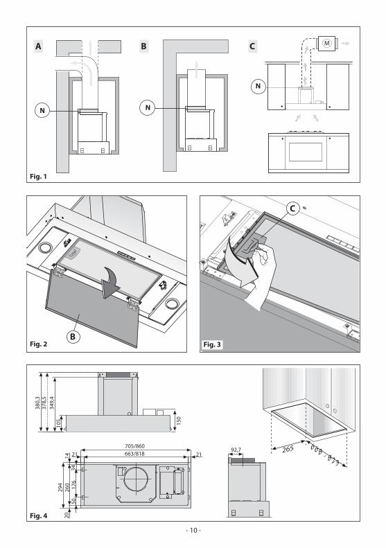
Carefully read the following important information regarding installation safety and maintenance. Keep this information booklet accessible for further consultations. The appliance has been designed for use in the ducting version (air exhaust to the outside – Fig.1B), filtering version (air circulation on the inside – Fig.1A) or with external motor (Fig.1C).
SAFETY PRECAUTION
1. Take care when the cooker hood is operating simultaneously with an open fireplace or burner that depend on the air in the environment. The cooker hood removes air from the environment which a burner or fireplace need for combustion. The negative pressure in the environment must not exceed 4Pa (4x10⁻⁵ bar). Provide adequate ventilation for a safe operation. Follow the local laws applicable for external air evacuation.
Before connecting the model to the electricity network:- Check the data plate (positioned inside the appliance) to ascertain that the voltage and power correspond to the network and the socket is suitable. If in doubt ask a qualified electrician.- If the power supply cable is damaged, it must be replaced with another cable or a special assembly, which may be obtained direct from the manufacturer.
2. Warning !In certain circumstances electrical appliances may be a danger hazard.A) Do not check the status of the filters while the cooker hood is operatingB) Do not touch bulbs or adjacent areas, during or straight after prolonged use C) Flambè cooking is prohibited underneath the cooker hoodD) Avoid free flame, as it can damage the filters and is a fire hazardE) Constantly check food fr ying to avoid overheated oil becoming a fire hazardF) Disconnect the electrical plug prior to any maintenanceG) This appliance is not intended for use by young children or infirm persons without supervisionH) Young children should be supervised to ensure they do not play with the applianceI) There shall be adequate ventilation of the room when the rangehood is used at the same time as appliances burning gas or other fuelsL) There is a risk of fire if cleaning is not carried out in accordance with the instructions
This appliance conforms to the European Directive EC/2002/96, Waste Electrical and Electronic Equipment (WEEE). By making sure that this appliance is disposed of in a suitable manner, the user is helping to prevent potential damage to the environment or to public health.
The symbol on the product or on the accompanying paperwork indicates that the appliance should not be treated as domestic waste, but should be delivered to a suitable electric and electronic appliance recycling collection point. Follow local guidelines when disposing of waste. For more information on the treatment, re-use and recycling of this product, please contact your local authority, domestic waste collection service or the shop where the appliance was purchased.
INSTALLATION INSTRUCTIONS
Assembly and electrical connections must be carried out by licenced personnel.
• Electric ConnectionThe appliance has been manufactured as a class II, therefore no earth cable is necessary.The plug must be easily accessible after the installation of the appliance.If the appliance is equipped with power cord without plug, a suitably dimensioned omnipolar switch with 3 mm minimum opening between contacts must be fitted between the appliance and the electricity supply in compliance with the load and current regulations.
The connection to the mains is carried out as follows: BROWN = L active
- 5 -
BLUE = N neutral• If the hob is electric, gas, or induction, the minimum distance between the lower part of the hood and the Hob burners or hotplates must be at least 65 cm.Exhaust: If a connection tube composed of two parts is used, the upper part must be placed outside or over the lower part. Do not connect the cooker hood exhaust to any conductor used to circulate hot air or for evacuating fumes from other appliances.
• We recommend the use of an air exhaust tube which has the same diameter as the air exhaust outlet hole (150 mm). If a pipe with a smaller diameter is used, the efficiency of the product may be reduced and its operation may become noisier.
• InstallationThe following instruction should be followed to carry out the correct installation of the cooker hood.1. Mounting of the cooker hood on the lower side of the cupboard.2. Select the version (extraction or filtration)3. Before starting to fix the hood, remove the anti-grease filter for easier handling:
- Open panel B as shown in Fig.2.- Pull handle C as shown in Fig.3.
• Fitting the cooker hood into the lower part of the wallcabinet
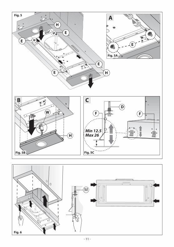
For all measurements relating to the cooker hood, please refer to Fig.4.Before fixing the cooker hood to the lower part of the cabinet, the following steps should be performed:
1- Remove the 4 screws E fixing the two cooker hood lamps H (RHS and LHS) in place as indicated in Fig. 5A.2- Remove the lamps H and disconnect the connectors W of the halogen lamps to make installation easier, as
indicated in Fig. 5B.3. Make sure the thickness of the cabinet falls within the range of values listed in Fig. 5C.
Fit the cooker hood in the cabinet (Fig. 6) and make sure the 4 springs are fixed in place well.Fix the cooker hood to the cabinet securely by using a screwdriver to tighten the screws M until the appliance is flush with the cabinet (Fig. 6).
4. Connect the connectors W of the halogen lamps again and reinstall the lamps H fixing them with the 4 screws E that were previously removed.
• Ducted versionThis appliance expels fumes, either through a perimeter wall or ceiling. It is therefore necessary to purchase a non-flammable air exhaust tube (not supplied) which complies with all current legislation and connect it to flange N (Fig.1B).
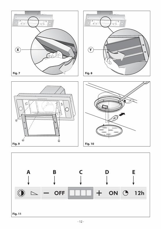
• Filter hoodPlease note:In order to transform the hood from ducted to recirculating the carbon filters must be ordered at your distributor as an accessory. We have two different types of carbon filters: Re-usable part no. ACK62260 (Fig.7) and disposable, part no. KIT0112 (Fig.8)
- To replace the extractable active carbon filters X, pull lever outwards as shown in Fig.7- To replace re-usable carbon filters Y, remove the brackets from their seat, pulling them outwards. (Fig.8)Fix the bracket (included in the product packaging) to the hood using the supplied screws (Fig. 9)
USE AND MAINTENANCE
• We recommend that the cooker hood is switched on before cooking.We also recommend that the appliance is left running for15 minutes after the food is cooked, in order to thoroughly eliminate all contaminated air.The effective performance of the cooker hood depends on constant maintenance; the anti-grease filter and the active carbon filter both require special attention.• The anti-grease filter is used to trap any grease particles suspended in the air, therefore is subject to saturation (the time it takes for the filter to become saturated depends on the way in which the appliance is used).-To prevent potential fire hazards, the anti-grease filters should be washed a minimum of every 2 months (it is
- 6 -
possible to use the dishwasher for this task).- After a few washes, the colour of the filters may change. This does not mean they have to be replaced.If the replacement and washing instructions are not followed, the anti-grease filters may present a fire hazard.• The active carbon filters are used to purify the air which is released back into the room.The filters are not washable or re-usable and must be replaced at least once every four months.The active carbon filter saturation level depends on the frequency with which the appliance is used, the type of cooking performed and the regularity with which the anti- grease filters are cleaned.• Clean the cooker hood frequently, both inside and outside, using a cloth which has been dampened with denatured alcohol or neutral, non-abrasive liquid detergents.• The light on the cooker hood is designed for use duringcooking and not for general room illumination.Extended use of the light reduces the average duration of the bulb.
• Replacing halogen light bulbs (Fig. 10).To replace the halogen light bulbs B, remove the glass paneC using a lever action on the relevant cracks. Replace the bulbs with new ones of the same type.Caution: do not touch the light bulb with bare hands.
• Commands (Fig. 11): Warning!- When activating or deactivating the operations or the alarm, the motor and lights must be switched off.- This product is supplied with an acoustic indicator (buzzer). Each time any button is pressed, this is confirmed by an acoustic indicator. - This function can be deactivated or activated, by simultaneously pressing the ON and TIMER buttons for five seconds.- If your product is a recirculating version, it is necessary to activate the active carbon filters indicator function which you find in the paragraph regarding this function.
Button A = light (Softlight)Starting:A brief pressure on the light button will turn on the light at the maximum intensity, activating the fast softlight function. Adjustment:By keeping the light button pressed, the intensity can be adjusted from maximum to minimum and vice-versa. Switching off:Quick pressure of the light button.
Button B = OFF and Speed reduction
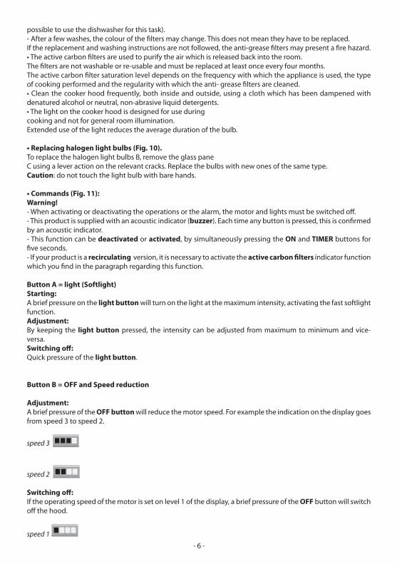
Adjustment:A brief pressure of the OFF button will reduce the motor speed. For example the indication on the display goes from speed 3 to speed 2.
speed 3
speed 2
Switching off:If the operating speed of the motor is set on level 1 of the display, a brief pressure of the OFF button will switch off the hood.
speed 1
- 7 -
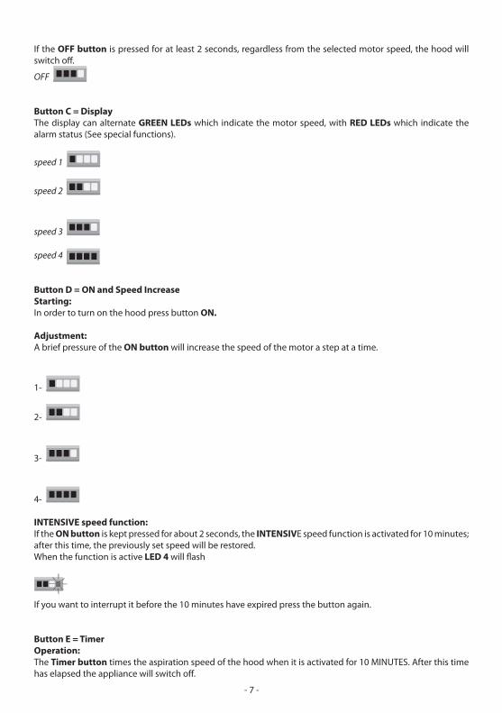
If the OFF button is pressed for at least 2 seconds, regardless from the selected motor speed, the hood will switch off.
OFF
Button C = Display The display can alternate GREEN LEDs which indicate the motor speed, with RED LEDs which indicate the alarm status (See special functions).
speed 1
speed 2
speed 3
speed 4
Button D = ON and Speed IncreaseStarting:In order to turn on the hood press button ON.
Adjustment:A brief pressure of the ON button will increase the speed of the motor a step at a time.
1-
2-
3-
4-
INTENSIVE speed function:If the ON button is kept pressed for about 2 seconds, the INTENSIVE speed function is activated for 10 minutes; after this time, the previously set speed will be restored.When the function is active LED 4 will flash
If you want to interrupt it before the 10 minutes have expired press the button again.
Button E = Timer Operation:The Timer button times the aspiration speed of the hood when it is activated for 10 MINUTES. After this time has elapsed the appliance will switch off.
- 8 -
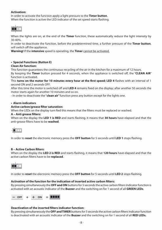
Activation:In order to activate the function apply a light pressure to the Timer button. When the function is active the LED indicator of the set speed starts flashing.
When the lights are on, at the end of the Timer function, these automatically reduce the light intensity by 30-40%.In order to deactivate the function, before the predetermined time, a further pressure of the Timer button, will switch off the appliance. Warning! If the intensive speed is operating, the Timer cannot be activated.
• Special Functions (Button E)Clean Air function: This function guarantees the continuous recycling of the air in the kitchen for a maximum of 12 hours.By keeping the Timer button pressed for 4 seconds, when the appliance is switched off, the “CLEAN AIR” function is activated. This turns on the motor for 10 minutes every hour at the first speed; LED 4 flashes with an interval of 1 second ON and 2 seconds OFF. After this time the motor is switched off and LED 4 remains fixed on the display; after another 50 seconds the motor starts again for another 10 minutes and so on.- In order to deactivate the “clean air” function press any button except for the lights one.
• Alarm indicators Active carbon/grease filter saturation:When the LEDs on the display turn Red this means that the filters must be replaced or washed.A – Anti grease filters:When on the display the LED 1 is RED and starts flashing, it means that 30 hours have elapsed and that the anti-grease filters have to be washed.
In order to reset the electronic memory press the OFF button for 5 seconds until LED 1 stops flashing.
B – Active Carbon filters:When on the display the LED 2 is RED and starts flashing, it means that 120 hours have elapsed and that the active carbon filters have to be replaced.
In order to reset the electronic memory press the OFF button for 5 seconds until LED 2 stops flashing.
Activation of the function for the indication of inserted active carbon filters: By pressing simultaneously the OFF and ON buttons for 5 seconds the active carbon filters indicator function is activated with an acoustic indicator of the Buzzer and the switching on for 1 second of all GREEN LEDs.
� �
Deactivation of the inserted filters indicator function: By pressing simultaneously the OFF and TIMER buttons for 5 seconds the active carbon filters indicator function is deactivated with an acoustic indicator of the Buzzer and the switching on for 1 second of all RED LEDs.
- 9 -
� �
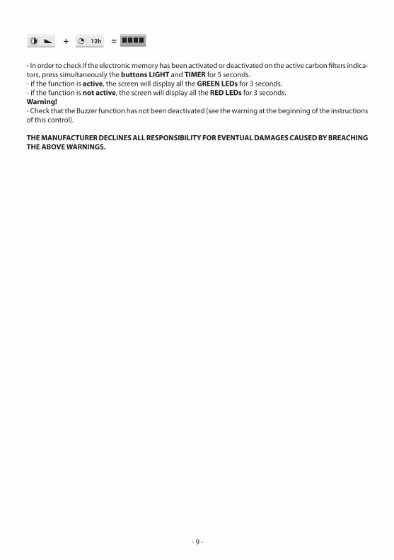
- In order to check if the electronic memory has been activated or deactivated on the active carbon filters indica-tors, press simultaneously the buttons LIGHT and TIMER for 5 seconds.- if the function is active, the screen will display all the GREEN LEDs for 3 seconds.- if the function is not active, the screen will display all the RED LEDs for 3 seconds.Warning!- Check that the Buzzer function has not been deactivated (see the warning at the beginning of the instructions of this control).
THE MANUFACTURER DECLINES ALL RESPONSIBILITY FOR EVENTUAL DAMAGES CAUSED BY BREACHING THE ABOVE WARNINGS.
�
�
������
� �� �
�
� �
�������������� ������
���
��� ���
����
��
���� ���������
���
������
������ ������
���
�����
�����
�����
���
- 10 -
�
�
�
�
�
�
������
������
�
�������
�
�
�
�������
�
�
�������
�
� �
�
��������������
- 11 -
������ ������
������ �������
�������
� �
� � � � �
- 12 -

- 13 -

- 14 -

- 15 -

3LIK0638


