44
PT 0200 BEN/I (1603) OPERATING INSTRUCTIONS EN Translation of the original instructions HIPACE 300 Turbopump
PT
0200
BE
N/I
(160
3)
OPERATING INSTRUCTIONS
ENTranslation of the original instructions
HIPACE 300Turbopump
Table of contents
Table of contents
1 About this manual . . . . . . . . . . . . . . . . . . . . . . . . . . . . . . . . . . . . . . . . . . . . . . . 4
1.1 Validity. . . . . . . . . . . . . . . . . . . . . . . . . . . . . . . . . . . . . . . . . . . . . . . . . . . . . 41.1.1 Applicable documents . . . . . . . . . . . . . . . . . . . . . . . . . . . . . . . . . . . 4
1.2 Conventions . . . . . . . . . . . . . . . . . . . . . . . . . . . . . . . . . . . . . . . . . . . . . . . . 41.2.1 Safety instructions. . . . . . . . . . . . . . . . . . . . . . . . . . . . . . . . . . . . . . 41.2.2 Pictographs . . . . . . . . . . . . . . . . . . . . . . . . . . . . . . . . . . . . . . . . . . . 51.2.3 Instructions in the text . . . . . . . . . . . . . . . . . . . . . . . . . . . . . . . . . . . 51.2.4 Abbreviations . . . . . . . . . . . . . . . . . . . . . . . . . . . . . . . . . . . . . . . . . 51.2.5 Symbols used . . . . . . . . . . . . . . . . . . . . . . . . . . . . . . . . . . . . . . . . . 5
2 Safety . . . . . . . . . . . . . . . . . . . . . . . . . . . . . . . . . . . . . . . . . . . . . . . . . . . . . . . . . 6
2.1 Safety precautions . . . . . . . . . . . . . . . . . . . . . . . . . . . . . . . . . . . . . . . . . . . 6
2.2 Protective equipment . . . . . . . . . . . . . . . . . . . . . . . . . . . . . . . . . . . . . . . . . 7
2.3 Proper use . . . . . . . . . . . . . . . . . . . . . . . . . . . . . . . . . . . . . . . . . . . . . . . . . 7
2.4 Improper use. . . . . . . . . . . . . . . . . . . . . . . . . . . . . . . . . . . . . . . . . . . . . . . . 8
3 Transport and storage. . . . . . . . . . . . . . . . . . . . . . . . . . . . . . . . . . . . . . . . . . . . 9
3.1 Transport. . . . . . . . . . . . . . . . . . . . . . . . . . . . . . . . . . . . . . . . . . . . . . . . . . . 9
3.2 Storage . . . . . . . . . . . . . . . . . . . . . . . . . . . . . . . . . . . . . . . . . . . . . . . . . . . . 9
4 Product description. . . . . . . . . . . . . . . . . . . . . . . . . . . . . . . . . . . . . . . . . . . . . 10
4.1 Product identification. . . . . . . . . . . . . . . . . . . . . . . . . . . . . . . . . . . . . . . . . 104.1.1 Pump types . . . . . . . . . . . . . . . . . . . . . . . . . . . . . . . . . . . . . . . . . . 104.1.2 Pump features. . . . . . . . . . . . . . . . . . . . . . . . . . . . . . . . . . . . . . . . 104.1.3 Variants . . . . . . . . . . . . . . . . . . . . . . . . . . . . . . . . . . . . . . . . . . . . . 104.1.4 Scope of delivery. . . . . . . . . . . . . . . . . . . . . . . . . . . . . . . . . . . . . . 10
4.2 Function . . . . . . . . . . . . . . . . . . . . . . . . . . . . . . . . . . . . . . . . . . . . . . . . . . 114.2.1 Cooling . . . . . . . . . . . . . . . . . . . . . . . . . . . . . . . . . . . . . . . . . . . . . 114.2.2 Rotor bearing . . . . . . . . . . . . . . . . . . . . . . . . . . . . . . . . . . . . . . . . 114.2.3 Drive . . . . . . . . . . . . . . . . . . . . . . . . . . . . . . . . . . . . . . . . . . . . . . . 11
4.3 Range of application . . . . . . . . . . . . . . . . . . . . . . . . . . . . . . . . . . . . . . . . . 12
5 Installation . . . . . . . . . . . . . . . . . . . . . . . . . . . . . . . . . . . . . . . . . . . . . . . . . . . . 13
5.1 Preparatory work. . . . . . . . . . . . . . . . . . . . . . . . . . . . . . . . . . . . . . . . . . . . 13
5.2 Set-up . . . . . . . . . . . . . . . . . . . . . . . . . . . . . . . . . . . . . . . . . . . . . . . . . . . . 135.2.1 Earthquake safety . . . . . . . . . . . . . . . . . . . . . . . . . . . . . . . . . . . . . 145.2.2 Use of a splinter shield or protection screen . . . . . . . . . . . . . . . . . 145.2.3 Vibration damper. . . . . . . . . . . . . . . . . . . . . . . . . . . . . . . . . . . . . . 14
5.3 Mounting orientation . . . . . . . . . . . . . . . . . . . . . . . . . . . . . . . . . . . . . . . . . 15
5.4 Connecting the high vacuum side. . . . . . . . . . . . . . . . . . . . . . . . . . . . . . . 165.4.1 Installation of ISO-K flange with ISO-K flange . . . . . . . . . . . . . . . 165.4.2 Installation of ISO-K flange with ISO-F flange. . . . . . . . . . . . . . . . 175.4.3 Installation of ISO-F with ISO-F flange . . . . . . . . . . . . . . . . . . . . . 185.4.4 Installation of CF- flanges . . . . . . . . . . . . . . . . . . . . . . . . . . . . . . . 19
5.5 Connecting the fore-vacuum side . . . . . . . . . . . . . . . . . . . . . . . . . . . . . . . 20
5.6 Connections to the turbopump . . . . . . . . . . . . . . . . . . . . . . . . . . . . . . . . . 215.6.1 Electronic drive unit. . . . . . . . . . . . . . . . . . . . . . . . . . . . . . . . . . . . 215.6.2 Earthing. . . . . . . . . . . . . . . . . . . . . . . . . . . . . . . . . . . . . . . . . . . . . 215.6.3 Power and electrical supply . . . . . . . . . . . . . . . . . . . . . . . . . . . . . 215.6.4 Remote plug . . . . . . . . . . . . . . . . . . . . . . . . . . . . . . . . . . . . . . . . . 22
5.7 Accessory connection . . . . . . . . . . . . . . . . . . . . . . . . . . . . . . . . . . . . . . . . 225.7.1 Air cooling . . . . . . . . . . . . . . . . . . . . . . . . . . . . . . . . . . . . . . . . . . . 235.7.2 Venting valve. . . . . . . . . . . . . . . . . . . . . . . . . . . . . . . . . . . . . . . . . 235.7.3 Sealing gas connection . . . . . . . . . . . . . . . . . . . . . . . . . . . . . . . . . 245.7.4 Heating jacket . . . . . . . . . . . . . . . . . . . . . . . . . . . . . . . . . . . . . . . . 245.7.5 Water cooling . . . . . . . . . . . . . . . . . . . . . . . . . . . . . . . . . . . . . . . . 26
2
Table of contents
6 Operation . . . . . . . . . . . . . . . . . . . . . . . . . . . . . . . . . . . . . . . . . . . . . . . . . . . . . 27
6.1 Commissioning . . . . . . . . . . . . . . . . . . . . . . . . . . . . . . . . . . . . . . . . . . . . . 27
6.2 Operation modes . . . . . . . . . . . . . . . . . . . . . . . . . . . . . . . . . . . . . . . . . . . 27
6.3 Function description . . . . . . . . . . . . . . . . . . . . . . . . . . . . . . . . . . . . . . . . . 276.3.1 Operation without operating unit . . . . . . . . . . . . . . . . . . . . . . . . . . 286.3.2 Operation via "remote" connection . . . . . . . . . . . . . . . . . . . . . . . . 286.3.3 Operation with DCU or HPU . . . . . . . . . . . . . . . . . . . . . . . . . . . . . 286.3.4 Operation via fieldbus . . . . . . . . . . . . . . . . . . . . . . . . . . . . . . . . . . 28
6.4 Monitoring of the operation conditions . . . . . . . . . . . . . . . . . . . . . . . . . . . 286.4.1 Temperature monitoring . . . . . . . . . . . . . . . . . . . . . . . . . . . . . . . . 286.4.2 Operation display via LED. . . . . . . . . . . . . . . . . . . . . . . . . . . . . . . 29
6.5 Switching off and venting . . . . . . . . . . . . . . . . . . . . . . . . . . . . . . . . . . . . . 296.5.1 Switching off . . . . . . . . . . . . . . . . . . . . . . . . . . . . . . . . . . . . . . . . . 296.5.2 Venting . . . . . . . . . . . . . . . . . . . . . . . . . . . . . . . . . . . . . . . . . . . . . 29
7 Maintenance / replacement. . . . . . . . . . . . . . . . . . . . . . . . . . . . . . . . . . . . . . . 30
7.1 Maintenance intervals and responsibilities . . . . . . . . . . . . . . . . . . . . . . . . 30
7.2 Replacing the operating fluid reservoir . . . . . . . . . . . . . . . . . . . . . . . . . . . 30
7.3 Replacing the electronic drive unit . . . . . . . . . . . . . . . . . . . . . . . . . . . . . . 317.3.1 Rotation speed set value. . . . . . . . . . . . . . . . . . . . . . . . . . . . . . . . 32
8 Decommissioning . . . . . . . . . . . . . . . . . . . . . . . . . . . . . . . . . . . . . . . . . . . . . . 33
8.1 Shutting down for longer periods . . . . . . . . . . . . . . . . . . . . . . . . . . . . . . . 33
8.2 Re-starting . . . . . . . . . . . . . . . . . . . . . . . . . . . . . . . . . . . . . . . . . . . . . . . . 33
8.3 Disposal . . . . . . . . . . . . . . . . . . . . . . . . . . . . . . . . . . . . . . . . . . . . . . . . . . 33
9 Malfunctions . . . . . . . . . . . . . . . . . . . . . . . . . . . . . . . . . . . . . . . . . . . . . . . . . . 34
9.1 Rectifying malfunctions . . . . . . . . . . . . . . . . . . . . . . . . . . . . . . . . . . . . . . . 34
10 Service . . . . . . . . . . . . . . . . . . . . . . . . . . . . . . . . . . . . . . . . . . . . . . . . . . . . . . . 35
11 Spare parts HiPace 300 . . . . . . . . . . . . . . . . . . . . . . . . . . . . . . . . . . . . . . . . . . 36
12 Accessories . . . . . . . . . . . . . . . . . . . . . . . . . . . . . . . . . . . . . . . . . . . . . . . . . . . 37
12.1 HiPace 300, 24 V DC . . . . . . . . . . . . . . . . . . . . . . . . . . . . . . . . . . . . . . . . 37
12.2 Differences at HiPace 300, 48 V DC. . . . . . . . . . . . . . . . . . . . . . . . . . . . . 39
13 Technical data and dimensions . . . . . . . . . . . . . . . . . . . . . . . . . . . . . . . . . . . 40
13.1 General . . . . . . . . . . . . . . . . . . . . . . . . . . . . . . . . . . . . . . . . . . . . . . . . . . . 40
13.2 HiPace 300, 24 V DC . . . . . . . . . . . . . . . . . . . . . . . . . . . . . . . . . . . . . . . . 40
13.3 Differences at HiPace 300, 48 V DC. . . . . . . . . . . . . . . . . . . . . . . . . . . . . 41
13.4 Dimensions . . . . . . . . . . . . . . . . . . . . . . . . . . . . . . . . . . . . . . . . . . . . . . . . 42
Declaration of conformity . . . . . . . . . . . . . . . . . . . . . . . . . . . . . . . . . . . . . . . . 43
3
About this manual
1 About this manual
1.1 ValidityThis operating manual is for customers of Pfeiffer Vacuum. It describes the functioning of the designated product and provides the most important information for safe use of the unit. The description follows applicable EU guidelines. All information provided in this operating manual refers to the current state of the product's development. The documen-tation remains valid as long as the customer does not make any changes to the product.
Up-to-date operating instructions can also be downloaded from www.pfeiffer-vacuum.com.
1.1.1 Applicable documents
*also available via www.pfeiffer-vacuum.com
1.2 Conventions
1.2.1 Safety instructions
The safety instructions in Pfeiffer Vacuum operating instructions are the result of risk evaluations and hazard analyses and are oriented on international certification stan-dards as specified by UL, CSA, ANSI Z-535, SEMI S1, ISO 3864 and DIN 4844. In this document, the following hazard levels and information are considered:
HiPace 300, depending on the model Operating instructionsOperating instructions "Electronic drive unit TC 400", standard PT 0203 BN*
Operating instructions "Electronic drive unit TC 400 PB", Profibus PT 0244 BN*
Operating instructions "Electronic drive unit TC 400 E74", acc. Semi E74 PT 0302 BN*
Operating instructions "Electronic drive unit TC 400 DN", DeviceNet PT 0352 BN*
Operating instructions "Electronic drive unit TC 400 EC", EtherCAT PT 0452 BN*
Declaration of conformity Part of this document
DANGER
Imminent danger
Indicates an imminent hazardous situation that will result in death or serious injury.
WARNING
Possibly imminent danger
Indicates an imminent hazardous situation that can result in death or serious injury.
CAUTION
Possibly imminent danger
Indicates an imminent hazardous situation that can result in minor or moderate injury.
NOTICE
Command or note
Command to perform an action or information about properties, the disregarding of which may result in damage to the product.
4

About this manual
1.2.2 Pictographs
1.2.3 Instructions in the text
Work instruction: here you have to do something.
1.2.4 Abbreviations
DCU: Display Control Unit
HPU: Handheld Programming Unit
TC: Electronic drive unit for turbopump
TPS: Mains pack
1.2.5 Symbols used
The following symbols are used consistently throughout the diagrams:
High vacuum flange
Fore-vacuum flange
Vacuum flange of the backing pump
Exhaust flange of the backing pump
Electrical connection
Sealing gas connection
Venting connection
Cooling water connection
Prohibition of an action to avoid any risk of accidents, the disregarding of which may result in serious accidents
Warning of a displayed source of danger in connection with operation of the unit or equipment
Command to perform an action or task associated with a source of dan-ger, the disregarding of which may result in serious accidents
Important information about the product or this document
V
5
Safety
2 Safety
2.1 Safety precautions
● Do not expose any body parts to the vacuum.
● Observe all safety and accident prevention regulations.
● Regularly check the proper observance of all safety measures.
● Power supply: The turbopump power supply must apply to the requirements of dou-ble insulation between mains input voltage and operating voltage according to the reg-ulations of IEC 61010 and IEC 60950. Therefore Pfeiffer Vacuum recommends to use exclusively original-power packs and -accessories. Only in this case Pfeiffer Vacuum is able to guarantee the compliance of the European and North American guidelines.
● A safe connection to the protective earthing conductor (PE) is recommended (protec-tion class III).
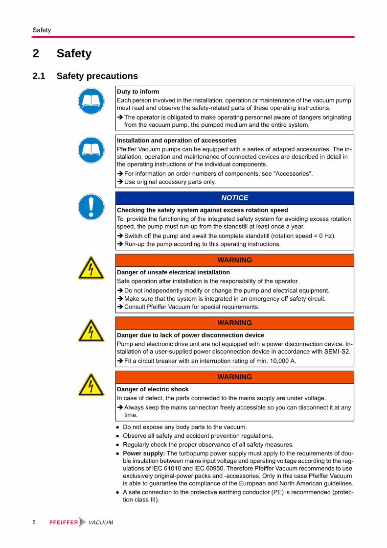
Duty to inform
Each person involved in the installation, operation or maintenance of the vacuum pump must read and observe the safety-related parts of these operating instructions.
The operator is obligated to make operating personnel aware of dangers originating from the vacuum pump, the pumped medium and the entire system.
Installation and operation of accessories
Pfeiffer Vacuum pumps can be equipped with a series of adapted accessories. The in-stallation, operation and maintenance of connected devices are described in detail in the operating instructions of the individual components.
For information on order numbers of components, see "Accessories".Use original accessory parts only.
NOTICE
Checking the safety system against excess rotation speed
To provide the functioning of the integrated safety system for avoiding excess rotation speed, the pump must run-up from the standstill at least once a year.
Switch off the pump and await the complete standstill (rotation speed = 0 Hz).Run-up the pump according to this operating instructions.
WARNING
Danger of unsafe electrical installation
Safe operation after installation is the responsibility of the operator.
Do not independently modify or change the pump and electrical equipment.Make sure that the system is integrated in an emergency off safety circuit.Consult Pfeiffer Vacuum for special requirements.
WARNING
Danger due to lack of power disconnection device
Pump and electronic drive unit are not equipped with a power disconnection device. In-stallation of a user-supplied power disconnection device in accordance with SEMI-S2.
Fit a circuit breaker with an interruption rating of min. 10,000 A.
WARNING
Danger of electric shock
In case of defect, the parts connected to the mains supply are under voltage.
Always keep the mains connection freely accessible so you can disconnect it at any time.
6

Safety
● Do not loosen any plug connection during operations.
● Wait for the rotor to reach standstill before peforming work on the high vacuum flange.
● Keep leads and cables well away from hot surfaces (> 70 °C).
● Never fill or operate turbopump with cleaning agent.
● Do not operate the turbopump with open high vacuum flange.
● Do not carry out any unauthorized modifications or conversions to the pump.
● When returning the turbopump observe the shipping instructions.
2.2 Protective equipmentDetermined situations concerning the handling of vacuum pumps require wearing of per-sonal protective equipment. The owner, respectively the employer are obligated to pro-vide an adequate equipment to any operating persons.
2.3 Proper use
DANGER
Danger to health by hazardous substances during maintenance or installation
Depending on the process vacuum pumps, components or operating fluids can be con-taminated by toxic, reactive or radioactive substances.
Wear adequate protective equipment during maintenance and repairs or in case of reinstallation.
kg
WARNING
Risk of injury through falling objects
When transporting vacuum pumps by hand, there is a danger through loads slipping and falling down.
Carry small and mid-size vacuum pumps two-handed.Carry vacuum pumps > 20 kg by a suitable lifting device.Wear safety shoes with steel toe cap according to directive EN 347.
CAUTION
Risk of injury through hot surfaces
Vacuum pumps can become hot during operation.
Allow the pump to cool before maintenance and repairs. If necessary wear protective gloves according to EN 420.
CAUTION
Risk of injury through sharp edges
Rotor and stator disks of turbopumps have very sharp edges.
Before any working wait for the complete standstill of the pump.Do not reach in the high vacuum flange. If necessary wear protective gloves according to EN 420.
NOTICE
EC conformity
The manufacturer's declaration of conformity becomes invalid if the operator modifies the original product or installs additional components.
Following installation into a plant and before commissioning, the operator must check the entire system for compliance with the valid EU directives and reassess it accord-ingly.
7
Safety
● The vacuum pump may only be used to generate a vacuum.
● Only operate the turbopump with an approved backing pump.
2.4 Improper useImproper use will cause all claims for liability and warranties to be forfeited. Improper use is defined as usage for purposes deviating from those mentioned above, especially:
● installation of the pump with unspecified mounting material
● pumping of corrosive or explosive media
● pumping of condensing vapors
● pumping of liquids
● pumping of dusts
● operation with improper high gas throughput
● operation with improper high fore-vacuum pressures
● operation with improper gas mode
● operation with improper high levels of insulated heat input
● operation in improper high magnetic fields
● venting with improper high venting rates
● use of the vacuum pump to generate pressure
● operation of the devices in areas with ionizing radiation
● operation in potentially explosive areas
● use of the devices in systems in which impact-like stress and vibrations or periodic forces affect the devices
● use of accessories or spare parts, which are not named in this manual
warranty seal Closure seal
The product is sealed at the factory. Damaging or removal of a closure seal leads to the loss of liability and warranty entitlements.
Do not open the product within its warranty period!For process-related shorter maintenance intervals please contact the Pfeiffer Vacu-
um Service.
8

Transport and storage
3 Transport and storage
3.1 TransportReuse the transport container of the vacuum pump.
– Transport or ship vacuum pumps in the original packing preferably.
Only remove the protective covers from the high vacuum and the fore-vacuum side immediately before connection.
Keep the original protective covers.
Always transport the turbopump in its upright position.
3.2 StorageClose the flange openings by using the original protective covers.
Close further connection ports by using the corresponding protective covers.
Store the pump only indoors at temperatures between -25 °C and +55 °C.
In rooms with moist or aggressive atmospheres, the pump must be airproof shrink-wrapped in a plastic bag together with a bag of desiccant.
9
Product description
4 Product description
4.1 Product identification
4.1.1 Pump types
The product designation consists of a family designation (1), the size (2), which is orient-ed on the pumping speed, and if applicable the additional properties (3) of the pump.
HiPace(1) 300(2) (3)
4.1.2 Pump features
This product has been tested to the requirements of CAN/CSA-C22.2 No. 61010-1, sec-ond edition, including Amendment 1, or a later version of the same standard incorporat-ing the same level of testing requirements.
For information about other certifications, if applicable, please see the signet on the prod-uct or:
● www.tuvdotcom.com
● TUVdotCOM-ID 0000021320
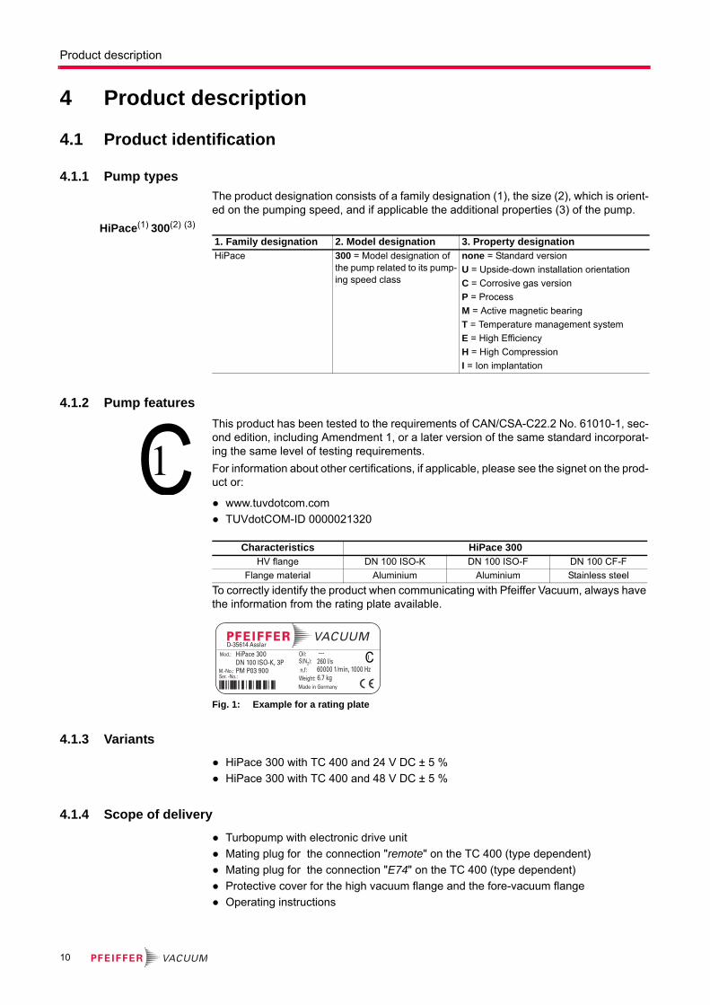
To correctly identify the product when communicating with Pfeiffer Vacuum, always have the information from the rating plate available.
Fig. 1: Example for a rating plate
4.1.3 Variants
● HiPace 300 with TC 400 and 24 V DC ± 5 %
● HiPace 300 with TC 400 and 48 V DC ± 5 %
4.1.4 Scope of delivery
● Turbopump with electronic drive unit
● Mating plug for the connection "remote" on the TC 400 (type dependent)
● Mating plug for the connection "E74" on the TC 400 (type dependent)
● Protective cover for the high vacuum flange and the fore-vacuum flange
● Operating instructions
1. Family designation 2. Model designation 3. Property designationHiPace 300 = Model designation of
the pump related to its pump-ing speed class
none = Standard version
U = Upside-down installation orientation
C = Corrosive gas version
P = Process
M = Active magnetic bearing
T = Temperature management system
E = High Efficiency
H = High Compression
I = Ion implantation
Characteristics HiPace 300HV flange DN 100 ISO-K DN 100 ISO-F DN 100 CF-F
Flange material Aluminium Aluminium Stainless steel
Mod.:
M.-No.:Ser. -No.:
Oil:S(N2):n,f:
Made in Germany
HiPace 300DN 100 ISO-K, 3PPM P03 900
---260 l/s60000 1/min, 1000 Hz
Weight: 6.7 kg
D-35614 Asslar
10
Product description
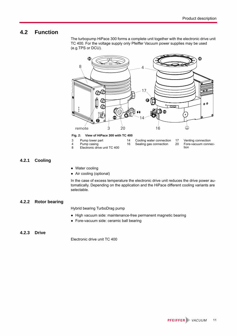
4.2 FunctionThe turbopump HiPace 300 forms a complete unit together with the electronic drive unit TC 400. For the voltage supply only Pfeiffer Vacuum power supplies may be used (e.g.TPS or DCU).
4.2.1 Cooling
● Water cooling
● Air cooling (optional)
In the case of excess temperature the electronic drive unit reduces the drive power au-tomatically. Depending on the application and the HiPace different cooling variants are selectable.
4.2.2 Rotor bearing
Hybrid bearing TurboDrag pump
● High vacuum side: maintenance-free permanent magnetic bearing
● Fore-vacuum side: ceramic ball bearing
4.2.3 Drive
Electronic drive unit TC 400
Fig. 2: View of HiPace 300 with TC 400
3 Pump lower part4 Pump casing8 Electronic drive unit TC 400
14 Cooling water connection16 Sealing gas connection
17 Venting connection20 Fore-vacuum connec-
tion
remote 20
17
163
14
48
11

Product description
4.3 Range of applicationThe pump HiPace 300 must be installed and operated under the following ambient con-ditions:
Installation location weather protected (indoors)
Protection category IP 54
Protection class III
Temperature +5 °C to +35 °C with air cooling
+5 °C to +40 °C with water cooling
Relative humidity max. 80 %, at T 31 °C, up to max. 50% at T 40 °C
Atmospheric pressure 750 hPa - 1060 hPa
Installation altitude 2000 m max.
Degree of pollution 2
Permissible surr. magnetic field 5.5 mT
Overvoltage category II
Connection voltage TC, depending on the variants
24 V DC ±5%
48 V DC ±5%
Remarks to ambient conditions
The specified permissible ambient temperatures apply to operation of the turbopump at maximum permissible fore-vacuum pressure or at maximum gas throughput depending on the cooling method. The turbopump is intrinsically safe by a redundant temperature monitoring.
● By reducing the fore-vacuum pressure or gas throughput, the turbopump can be op-erated at higher ambient temperatures.
● If the maximum permissible operating temperature of the turbopump is exceeded, the electronic drive unit reduces drive power first and switches off then, if necessary.
12
Installation
5 Installation
5.1 Preparatory workWhen installing the pump, observe the following conditions:
● the ambient conditions specified for the range of application
● When using a casing heating and a water cooling unit the temperature of the connect-ed flange of the vacuum chamber must not exceed 120 °C.
● The pump may be fastened to the floor only after consultation with Pfeiffer Vacuum.
● It is not allowed to operate the device in systems where impact-like stresses and vi-brations or periodically forces occur.
Ensure sufficient cooling for the turbopump.
Where magnetic fields > 5.5 mT are involved, a suitable shielding must be used. Check installation location and consult Pfeiffer Vacuum if needed!
The maximum permissible rotor temperature for the turbopump is 90 °C. If high tem-peratures arise for process reasons, the radiated heat input must not exceed 2.4 W. Install suitable screening sheets, if necessary (design information on request).
5.2 Set-up● Ensure the greatest possible cleanliness when installing any high vacuum parts. Un-
clean components prolong the pump-down time.
● All flange components must be grease-free, dust-free and dry at installation.
● The operating fluid reservoir is already installed and filled for the turbopump HiPace 300.
WARNING
Danger from the turbopump being ripped off
If the rotor is suddenly blocked, torques of up to 2000 Nm could occur, which could cause the turbopump to be ripped off if it is not properly affixed. The energy that this would release could throw the entire pump or pieces from its interior through the room. That would cause severe, possibly fatal, injuries as well as serious property damage.
Carefully follow the installation instructions in this handbook.Only use approved original parts from Pfeiffer Vacuum (Accessories) for the installa-
tion.
Installation and operation of accessories
Pfeiffer Vacuum pumps can be equipped with a series of adapted accessories. The in-stallation, operation and maintenance of connected devices are described in detail in the operating instructions of the individual components.
For information on order numbers of components, see "Accessories".Use original accessory parts only.
13
Installation
5.2.1 Earthquake safety
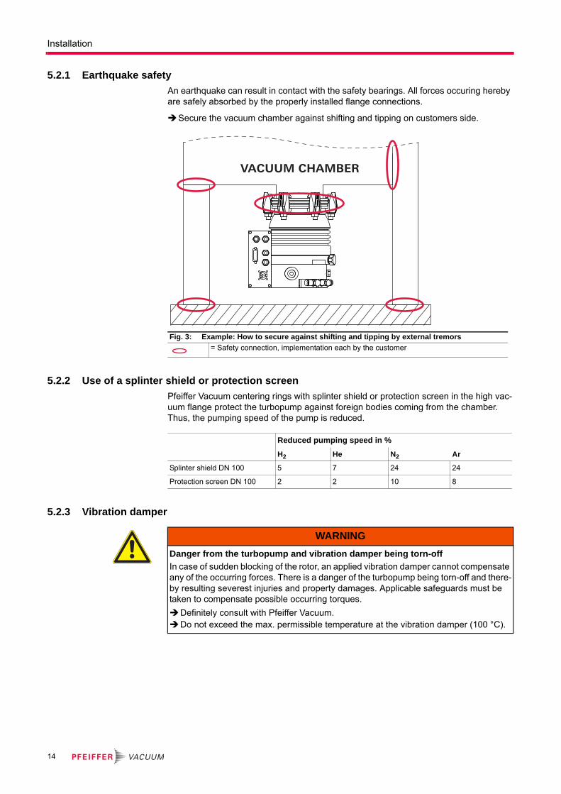
An earthquake can result in contact with the safety bearings. All forces occuring hereby are safely absorbed by the properly installed flange connections.
Secure the vacuum chamber against shifting and tipping on customers side.
5.2.2 Use of a splinter shield or protection screen
Pfeiffer Vacuum centering rings with splinter shield or protection screen in the high vac-uum flange protect the turbopump against foreign bodies coming from the chamber. Thus, the pumping speed of the pump is reduced.
5.2.3 Vibration damper
Fig. 3: Example: How to secure against shifting and tipping by external tremors
= Safety connection, implementation each by the customer
VACUUM CHAMBER
Reduced pumping speed in %
H2 He N2 Ar
Splinter shield DN 100 5 7 24 24
Protection screen DN 100 2 2 10 8
WARNING
Danger from the turbopump and vibration damper being torn-off
In case of sudden blocking of the rotor, an applied vibration damper cannot compensate any of the occurring forces. There is a danger of the turbopump being torn-off and there-by resulting severest injuries and property damages. Applicable safeguards must be taken to compensate possible occurring torques.
Definitely consult with Pfeiffer Vacuum. Do not exceed the max. permissible temperature at the vibration damper (100 °C).
14
Installation
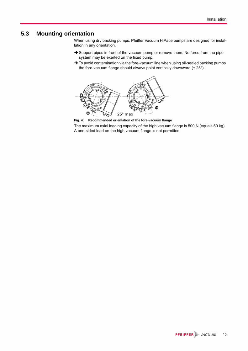
5.3 Mounting orientationWhen using dry backing pumps, Pfeiffer Vacuum HiPace pumps are designed for instal-lation in any orientation.
Support pipes in front of the vacuum pump or remove them. No force from the pipe system may be exerted on the fixed pump.
To avoid contamination via the fore-vacuum line when using oil-sealed backing pumps the fore-vacuum flange should always point vertically downward (± 25°).
Fig. 4: Recommended orientation of the fore-vacuum flange
The maximum axial loading capacity of the high vacuum flange is 500 N (equals 50 kg). A one-sided load on the high vacuum flange is not permitted.
25° maxVV
VV
15
Installation
5.4 Connecting the high vacuum sideIf the rotor is suddenly blocked, the torques arising from the system and the high vacuum flange must be absorbed. Only the components listed in the following can be used to fas-ten the turbopumps to the high vacuum flange. The installation elements for turbopumps are special designs by Pfeiffer Vacuum. In all operating conditions, the tensile strength of the flange material must be at least 170 N/mm2.
Secure the vacuum chamber against shifting and tipping on customers side.
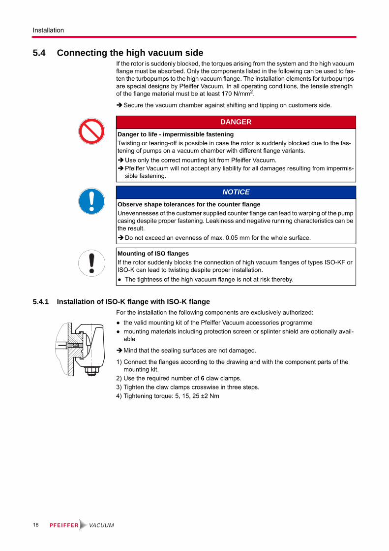
5.4.1 Installation of ISO-K flange with ISO-K flange
For the installation the following components are exclusively authorized:
● the valid mounting kit of the Pfeiffer Vacuum accessories programme
● mounting materials including protection screen or splinter shield are optionally avail-able
Mind that the sealing surfaces are not damaged.
1) Connect the flanges according to the drawing and with the component parts of the mounting kit.
2) Use the required number of 6 claw clamps.
3) Tighten the claw clamps crosswise in three steps.
4) Tightening torque: 5, 15, 25 ±2 Nm
DANGER
Danger to life - impermissible fastening
Twisting or tearing-off is possible in case the rotor is suddenly blocked due to the fas-tening of pumps on a vacuum chamber with different flange variants.
Use only the correct mounting kit from Pfeiffer Vacuum.Pfeiffer Vacuum will not accept any liability for all damages resulting from impermis-
sible fastening.
NOTICE
Observe shape tolerances for the counter flange
Unevennesses of the customer supplied counter flange can lead to warping of the pump casing despite proper fastening. Leakiness and negative running characteristics can be the result.
Do not exceed an evenness of max. 0.05 mm for the whole surface.
Mounting of ISO flanges
If the rotor suddenly blocks the connection of high vacuum flanges of types ISO-KF or ISO-K can lead to twisting despite proper installation.
● The tightness of the high vacuum flange is not at risk thereby.
16
Installation
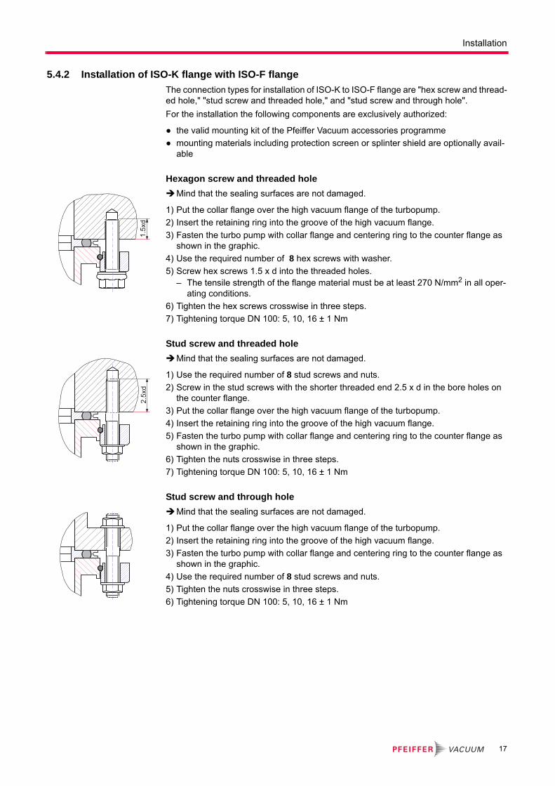
5.4.2 Installation of ISO-K flange with ISO-F flange
The connection types for installation of ISO-K to ISO-F flange are "hex screw and thread-ed hole," "stud screw and threaded hole," and "stud screw and through hole".
For the installation the following components are exclusively authorized:
● the valid mounting kit of the Pfeiffer Vacuum accessories programme
● mounting materials including protection screen or splinter shield are optionally avail-able
Hexagon screw and threaded hole
Mind that the sealing surfaces are not damaged.
1) Put the collar flange over the high vacuum flange of the turbopump.
2) Insert the retaining ring into the groove of the high vacuum flange.
3) Fasten the turbo pump with collar flange and centering ring to the counter flange as shown in the graphic.
4) Use the required number of 8 hex screws with washer.
5) Screw hex screws 1.5 x d into the threaded holes.– The tensile strength of the flange material must be at least 270 N/mm2 in all oper-
ating conditions.
6) Tighten the hex screws crosswise in three steps.
7) Tightening torque DN 100: 5, 10, 16 ± 1 Nm
Stud screw and threaded hole
Mind that the sealing surfaces are not damaged.
1) Use the required number of 8 stud screws and nuts.
2) Screw in the stud screws with the shorter threaded end 2.5 x d in the bore holes on the counter flange.
3) Put the collar flange over the high vacuum flange of the turbopump.
4) Insert the retaining ring into the groove of the high vacuum flange.
5) Fasten the turbo pump with collar flange and centering ring to the counter flange as shown in the graphic.
6) Tighten the nuts crosswise in three steps.
7) Tightening torque DN 100: 5, 10, 16 ± 1 Nm
Stud screw and through hole
Mind that the sealing surfaces are not damaged.
1) Put the collar flange over the high vacuum flange of the turbopump.
2) Insert the retaining ring into the groove of the high vacuum flange.
3) Fasten the turbo pump with collar flange and centering ring to the counter flange as shown in the graphic.
4) Use the required number of 8 stud screws and nuts.
5) Tighten the nuts crosswise in three steps.
6) Tightening torque DN 100: 5, 10, 16 ± 1 Nm
1.5x
d2.
5xd
17
Installation
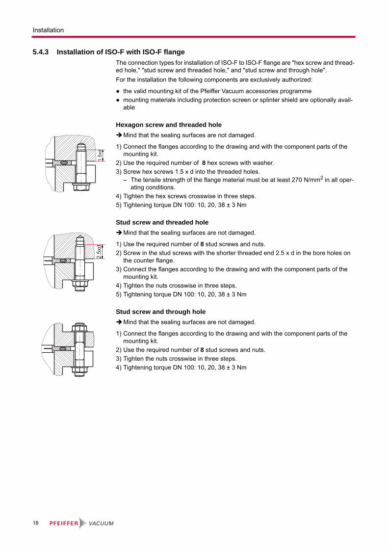
5.4.3 Installation of ISO-F with ISO-F flange
The connection types for installation of ISO-F to ISO-F flange are "hex screw and thread-ed hole," "stud screw and threaded hole," and "stud screw and through hole".
For the installation the following components are exclusively authorized:
● the valid mounting kit of the Pfeiffer Vacuum accessories programme
● mounting materials including protection screen or splinter shield are optionally avail-able
Hexagon screw and threaded hole
Mind that the sealing surfaces are not damaged.
1) Connect the flanges according to the drawing and with the component parts of the mounting kit.
2) Use the required number of 8 hex screws with washer.
3) Screw hex screws 1.5 x d into the threaded holes.– The tensile strength of the flange material must be at least 270 N/mm2 in all oper-
ating conditions.
4) Tighten the hex screws crosswise in three steps.
5) Tightening torque DN 100: 10, 20, 38 ± 3 Nm
Stud screw and threaded hole
Mind that the sealing surfaces are not damaged.
1) Use the required number of 8 stud screws and nuts.
2) Screw in the stud screws with the shorter threaded end 2.5 x d in the bore holes on the counter flange.
3) Connect the flanges according to the drawing and with the component parts of the mounting kit.
4) Tighten the nuts crosswise in three steps.
5) Tightening torque DN 100: 10, 20, 38 ± 3 Nm
Stud screw and through hole
Mind that the sealing surfaces are not damaged.
1) Connect the flanges according to the drawing and with the component parts of the mounting kit.
2) Use the required number of 8 stud screws and nuts.
3) Tighten the nuts crosswise in three steps.
4) Tightening torque DN 100: 10, 20, 38 ± 3 Nm
1.5x
d2.
5xd
18

Installation
5.4.4 Installation of CF- flanges
The connection types for installation of CF to CF flange are "hexagon screw and through hole", "stud screw and threaded hole" as well as "stud screw and through hole".
● the valid mounting kit of the Pfeiffer Vacuum accessories programme
● A copper seal
● protection screen or splinter shield are optionally
Hexagon screw and through hole
1) If used: Insert protective screen or splinter shield with the clamping lugs downward into the high vacuum flange of the turbopump.
2) Place the seal exactly in the hollow.
3) Connect the flanges using 16 hexagon-head screws (M8) with washers and bolts.
4) Tighten the screw connections circularly.
5) Tightening torque: 22 ± 2 Nm
6) After this, check the torque, since flowing of the sealing material may make it neces-sary to tighten the screws again.
Stud screw and threaded hole
1) Screw in the stud screws (16 pieces, M8) with the shorter threaded end into the threaded holes of the counter flange.
2) If used: Insert protective screen or splinter shield with the clamping lugs downward into the high vacuum flange of the turbopump.
3) Place the seal exactly in the hollow.
4) Connect the flanges using washers and nuts.
5) Tighten the screw connections circularly.
6) Tightening torque: 22 ± 2 Nm
7) After this, check the torque, since flowing of the sealing material may make it neces-sary to tighten the screws again.
Stud screw and through hole
1) If used: Insert protective screen or splinter shield with the clamping lugs downward into the high vacuum flange of the turbopump.
2) Place the seal exactly in the hollow.
3) Connect the flanges using 16 hexagon-head screws (M8) with washers and bolts.
4) Tighten the screw connections circularly.
5) Tightening torque: 22 ± 2 Nm
6) After this, check the torque, since flowing of the sealing material may make it neces-sary to tighten the screws again.
NOTICE
Assembly of CF flanges!
Loss of sealing capability due to a lack of cleanliness when handling the sealing and CF flange.
Assemble the sealing dry and oil-free.Always wear gloves when handling the components.Do not damage the surfaces and cutting edges.
19
Installation
5.5 Connecting the fore-vacuum sideRecommendation: As backing pump, use a suitable vacuum pump from the Pfeiffer Vacuum programme.
With rigid pipe connections: Install bellows for attenuation of vibrations in the connec-tion line.
Connect the fore-vacuum line with small-flange components or threaded hose cou-plings. Do not narrow the free cross section of the fore-vacuum flange!
The backing pump is connected electrically via a relay box.
For connection and operation of the backing pump see its operating instructions.
WARNING
Damage to health due to poisonous gases
Process gases can damage health and contaminate the environment.
Safely lead away the gas emission from the backing pump!Observe all safety recommendations of the gas producer.
Fig. 5: Connecting the backing pump
20 Fore-vacuum connection20a Backing pump
20.1 Centering ring20.2 Clamping ring
20.3 Vacuum components
20 20.1 20.2
20.3
20a
NOTICE
Design of the fore-vacuum connection regarding sudden twisting of the pump
If the rotor suddenly blocks the connection of high vacuum flanges of types ISO-KF or ISO-K can lead to twisting despite proper installation.
Keep masses small, which can be installed directly to the pump.Connect flexible line elements directly to the turbopump, if necessary.
Backing pump control
Backing pump control via electronic drive unit of the turbopump is possible using a relay box or respective connection cables of the accessory programme.
Refer to the operating instructions of the respective accessory.
20

Installation
5.6 Connections to the turbopump
5.6.1 Electronic drive unit
Turbopumps with integrated electronic drive unit are designed for various applications. Therefore different connection panels are available.
● TC 400 in standard version
● TC 400 PB for Profibus linking
● TC 400 E74 in dependence on specification SEMI E74
● TC 400 DN for DeviceNet linking
● TC 400 EC for EtherCAT linking
Detailed description for function, configuration and operation with the respective connec-tion panel are given in the specific operating instructions for the electronic drive unit.
5.6.2 Earthing
Pfeiffer Vacuum recommends to connect an appropriate earthing wire to derive applica-tive interferences.
Fig. 6: Installing the earthing connection
5.6.3 Power and electrical supply
For voltage supply of the electronic drive unit TC 400, only use original power supplies (e.g. TPS 310 or DCU 310). Use of other power supplies only after consultation with Pfei-ffer Vacuum. Connecting cables are available from the Pfeiffer Vacuum accessories.
Make sure that the voltage of the turbopump is valid.
M4
WARNING
Danger of electric shock
In case of defect, the parts connected to the mains supply are under voltage.
Always keep the mains connection freely accessible so you can disconnect it at any time.
HiPace V DC Drive unit Power supply Power supply with DCUHiPace 300 24 TC 400 TPS 310/311 DCU 310
HiPace 300 48 TC 400 TPS 400/401 DCU 400
21
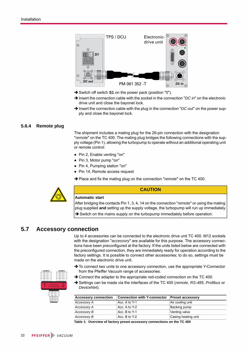
Installation
Switch off switch S1 on the power pack (position "0").
Insert the connection cable with the socket in the connection "DC in" on the electronic drive unit and close the bayonet lock.
Insert the connection cable with the plug in the connection "DC out" on the power sup-ply and close the bayonet lock.
5.6.4 Remote plug
The shipment includes a mating plug for the 26-pin connection with the designation "remote" on the TC 400. The mating plug bridges the following connections with the sup-ply voltage (Pin 1), allowing the turbopump to operate without an additional operating unit or remote control:
● Pin 2, Enable venting "on"
● Pin 3, Motor pump "on"
● Pin 4, Pumping station "on"
● Pin 14, Remote access request
Place and fix the mating plug on the connection "remote" on the TC 400.
5.7 Accessory connectionUp to 4 accessories can be connected to the electronic drive unit TC 400. M12 sockets with the designation "accessory" are available for this purpose. The accessory connec-tions have been preconfigured at the factory. If the units listed below are connected with the preconfigured connection, they are immediately ready for operation according to the factory settings. It is possible to connect other accessories; to do so, settings must be made on the electronic drive unit.
To connect two units to one accessory connection, use the appropriate Y-Connector from the Pfeiffer Vacuum range of accessories.
Connect the adapter to the appropriate red-coded connection on the TC 400.
Settings can be made via the interfaces of the TC 400 (remote, RS-485, Profibus or DeviceNet).
Table 1: Overview of factory preset accessory connections on the TC 400
DC out
S1
TPS / DCU Electronic-drive unit
DC inPM 061 352 -T
CAUTION
Automatic start
After bridging the contacts Pin 1, 3, 4, 14 on the connection "remote" or using the mating plug supplied and setting up the supply voltage, the turbopump will run up immediately.
Switch on the mains supply on the turbopump immediately before operation.
1 21 2Y-Connectorfor Accessories
Accessory connection Connection with Y-connector Preset accessoryAccessory A Acc. A to Y-1 Air cooling unit
Accessory A Acc. A to Y-2 Backing pump
Accessory B Acc. B to Y-1 Venting valve
Accessory B Acc. B to Y-2 Casing heating unit
22
Installation
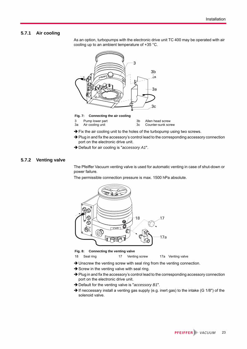
5.7.1 Air cooling
As an option, turbopumps with the electronic drive unit TC 400 may be operated with air cooling up to an ambient temperature of +35 °C.
Fix the air cooling unit to the holes of the turbopump using two screws.
Plug in and fix the accessory’s control lead to the corresponding accessory connection port on the electronic drive unit.
Default for air cooling is "accessory A1".
5.7.2 Venting valve
The Pfeiffer Vacuum venting valve is used for automatic venting in case of shut-down or power failure.
The permissible connection pressure is max. 1500 hPa absolute.
Unscrew the venting screw with seal ring from the venting connection.
Screw in the venting valve with seal ring.
Plug in and fix the accessory’s control lead to the corresponding accessory connection port on the electronic drive unit.
Default for the venting valve is "accessory B1".
If neccessary install a venting gas supply (e.g. inert gas) to the intake (G 1/8") of the solenoid valve.
Fig. 7: Connecting the air cooling
3 Pump lower part3a Air cooling unit
3b Allen head screw3c Counter-sunk screw
3
3a
3b
3c
Fig. 8: Connecting the venting valve
18 Seal ring 17 Venting screw 17a Venting valve
F17
17a
18
23
Installation
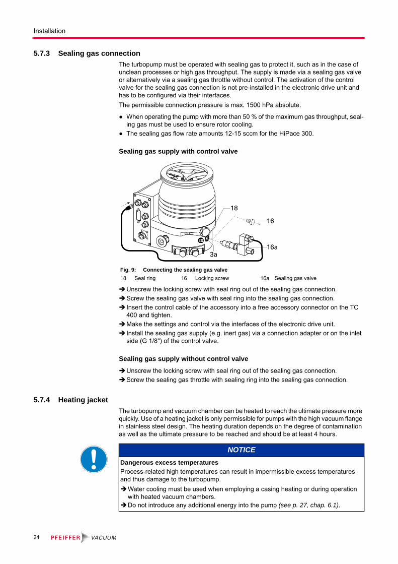
5.7.3 Sealing gas connection
The turbopump must be operated with sealing gas to protect it, such as in the case of unclean processes or high gas throughput. The supply is made via a sealing gas valve or alternatively via a sealing gas throttle without control. The activation of the control valve for the sealing gas connection is not pre-installed in the electronic drive unit and has to be configured via their interfaces.
The permissible connection pressure is max. 1500 hPa absolute.
● When operating the pump with more than 50 % of the maximum gas throughput, seal-ing gas must be used to ensure rotor cooling.
● The sealing gas flow rate amounts 12-15 sccm for the HiPace 300.
Sealing gas supply with control valve
Unscrew the locking screw with seal ring out of the sealing gas connection.
Screw the sealing gas valve with seal ring into the sealing gas connection.
Insert the control cable of the accessory into a free accessory connector on the TC 400 and tighten.
Make the settings and control via the interfaces of the electronic drive unit.
Install the sealing gas supply (e.g. inert gas) via a connection adapter or on the inlet side (G 1/8") of the control valve.
Sealing gas supply without control valve
Unscrew the locking screw with seal ring out of the sealing gas connection.
Screw the sealing gas throttle with sealing ring into the sealing gas connection.
5.7.4 Heating jacket
The turbopump and vacuum chamber can be heated to reach the ultimate pressure more quickly. Use of a heating jacket is only permissible for pumps with the high vacuum flange in stainless steel design. The heating duration depends on the degree of contamination as well as the ultimate pressure to be reached and should be at least 4 hours.
Fig. 9: Connecting the sealing gas valve
18 Seal ring 16 Locking screw 16a Sealing gas valve
SG
3a
16
16a
18
NOTICE
Dangerous excess temperatures
Process-related high temperatures can result in impermissible excess temperatures and thus damage to the turbopump.
Water cooling must be used when employing a casing heating or during operation with heated vacuum chambers.
Do not introduce any additional energy into the pump (see p. 27, chap. 6.1).
24

Installation
● When using a casing heating and a water cooling unit the temperature of the connect-ed flange of the vacuum chamber must not exceed 120 °C.
● The maximum permissible rotor temperature for the turbopump is 90 °C. If high tem-peratures arise for process reasons, the radiated heat input must not exceed 2.4 W. Install suitable screening sheets, if necessary (design information on request).
Bend open the outer heating jacket on the tensioning strap and place it sidewards on to the cylindrical segment of the pump casing.– Do not bend the heating straps!– The heating jacket must seat completely on the casing segment.
Fix the heating jacket with the fixing screw on the casing.– Observe the tightening torque for the fixing screw!
Table 2: Tightening torques for fixing screws of heating jackets
Plug in and fix the accessory’s control lead to the corresponding accessory connection port on the electronic drive unit.
Default for the casing heating is "accessory B2".
Establish the mains supply for the relay box according to the accessory operating in-structions.
CAUTION
Risk of burns
High temperatures arise when the turbopump or vacuum chamber are baked out. As a result, there is a danger of burns from touching hot parts, even after the casing heating is switched off!
Thermally insulate heating jacket, pump housing and vacuum chamber, if possible during installation.
Do not touch heating jacket, pump casing and vacuum chamber during bake out.
Fig. 10: Connecting the heating jacket
4 Pump casing4a Heating jacket
4b Fixing screw4c Heating relay box
4d Warning sticker
Fixing screw Tightening torque in cold condition
Tightening torque during the heating-up
Singular retightening af-ter the cooling down
M5 6 Nm 7 Nm 7 NmM6 11 Nm 12 Nm 12 Nm
H
4a
4d
4b
2x
4c
4
25
Installation
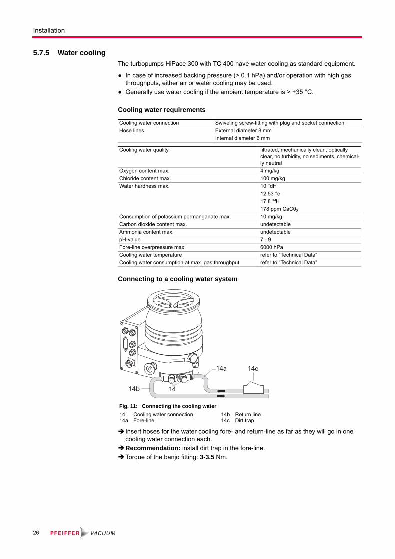
5.7.5 Water cooling
The turbopumps HiPace 300 with TC 400 have water cooling as standard equipment.
● In case of increased backing pressure (> 0.1 hPa) and/or operation with high gas throughputs, either air or water cooling may be used.
● Generally use water cooling if the ambient temperature is > +35 °C.
Cooling water requirements
Connecting to a cooling water system
Insert hoses for the water cooling fore- and return-line as far as they will go in one cooling water connection each.
Recommendation: install dirt trap in the fore-line.
Torque of the banjo fitting: 3-3.5 Nm.
Cooling water connection Swiveling screw-fitting with plug and socket connection
Hose lines External diameter 8 mm
Internal diameter 6 mm
Cooling water quality filtrated, mechanically clean, optically clear, no turbidity, no sediments, chemical-ly neutral
Oxygen content max. 4 mg/kg
Chloride content max. 100 mg/kg
Water hardness max. 10 °dH
12.53 °e
17.8 °fH
178 ppm CaC03
Consumption of potassium permanganate max. 10 mg/kg
Carbon dioxide content max. undetectable
Ammonia content max. undetectable
pH-value 7 - 9
Fore-line overpressure max. 6000 hPa
Cooling water temperature refer to "Technical Data"
Cooling water consumption at max. gas throughput refer to "Technical Data"
Fig. 11: Connecting the cooling water
14 Cooling water connection14a Fore-line
14b Return line14c Dirt trap
14
14a
14b
14c
26
Operation
6 Operation
6.1 CommissioningThe following important settings are programmed in the electronic drive unit ex factory.
● Parameter [P:027] Gas mode: 0 = heavy gases
● Parameter [P:700] Set value max. run-up time monitoring: 8 min
● Parameter [P:701] Rotation speed switchpoint: 80% of the nominal roation speed
● Parameter [P:707] Set value in rotation speed setting mode: 65 % of the nominal ro-tation speed
● Parameter [P:708] Set value power consumption: 100 %
● Parameter [P:720] Venting rotation speed at delayed venting: 50 % of the nominal ro-tation speed
● Parameter [P:721] Venting time: 3600 s
When water cooling is used: Open cooling water supply and check the flow.
When sealing gas is used: Open the sealing gas supply and check the flow.
Establish the mains for the power supply.
6.2 Operation modesThe following operation modes are available:
● Operation without operating unit
● Operation via "remote" connection
● Operation via RS-485 and Pfeiffer Vacuum display and control units or PC
● Operation via field bus
6.3 Function description
NOTICE
Risk of destroying the pump by inputting too much energy
Simultaneous loading by means of high drive power (gas flow rate, fore-vacuum pres-sure), high heat radiation, or strong magnetic fields results in uncontrolled heating of the rotor and may destroy the pump.
Reduced limit values apply when combining these loads. If necessary consult with Pfeiffer Vacuum.
NOTICE
Danger of the pump being destroyed
Pumping of gases with a higher molecular mass in the wrong gas mode can lead to de-struction of the pump.
Ensure the gas mode is correctly set.Contact Pfeiffer Vacuum before using gases with a greater molecular mass (> 80).
WARNING
Danger due to open high vacuum flange
The rotor of the turbopump turns at high speed. If the high vacuum flange is open, there is a danger of cut injuries and that the pump can be destroyed by objects falling into it.
Never operate the pump with an open high vacuum flange.
27

Operation
6.3.1 Operation without operating unit
For operation without the control unit, the 26-pole D-Sub plug must be in the "remote" connection on the TC 400.
Switch on the supply voltage with switch S1 on the power supply.
After operating voltage is applied, the TC 400 performs a self-test to check the supply voltage. Once the self-test has been successfully completed on the TC 400, the tur-bopump and the backing pump - if connected - begin to operate.
6.3.2 Operation via "remote" connection
Remote control is possible via the 26-pin D-sub connector labelled "remote" on the elec-tronic drive unit. The accessible individual functions are mapped to "PLC levels".
Consider the following manuals for the operation via remote control:● Operating instructions "Electronic drive unit TC 400"
6.3.3 Operation with DCU or HPU
Consider the following manuals for the operation via Pfeiffer Vacuum display and con-trol units:● Operating instructions "DCU"● Operating instructions "HPU"● Operating instructions "Electronic drive unit TC 400"
Switch on the supply voltage with switch S1 on the power supply or on the DCU 310.
Settings are possible via interface RS-485 by using DCU, HPU or PC.
6.3.4 Operation via fieldbus
Integrating and operating Pfeiffer Vacuum turbopumps in the customer's field bus system is possible for electronic drive units with a corresponding field bus panel.
Consider the following manuals for the operation via field bus:● Operating instructions for the electronic drive unit with the respective connection
panel
6.4 Monitoring of the operation conditions
6.4.1 Temperature monitoring
The drive power is reduced in case of impermissible motor temperature or impermissibly high housing temperature. This can cause falling below the rotation speed switchpoint and so result in turning off the turbopump.
CAUTION
Automatic start
After bridging the contacts Pin 1, 3, 4, 14 on the connection "remote" or using the mating plug supplied and setting up the supply voltage, the turbopump will run up immediately.
Switch on the mains supply on the turbopump immediately before operation.
28

Operation
6.4.2 Operation display via LED
LEDs in the front panel of the electronic drive unit show basic operating conditions of the turbopump. A differentiated malfunction and warning display is possible only for opera-tion with DCU or HPU.
Fig. 12: Behaviour and meaning of LEDs on the electronic drive unit
6.5 Switching off and venting
6.5.1 Switching off
After the turbopump is switched off, it must be vented to avoid contamination due to par-ticles streaming back from the fore-vacuum area.
Close the fore-vacuum: Switch off the backing pump or close a fore-vacuum valve.
Switch off the turbopump on the control unit or via remote control.
Venting (possibilities see below)
For water cooling: Shut off the water supply.
6.5.2 Venting
Manually venting
Open the venting screw (included) in the venting connection of the turbopump about one turn.
Venting with Pfeiffer Vacuum Venting Valve
Enable venting via the functions of the electronic drive unit.
Settings are possible via interface RS-485 by using DCU, HPU or PC.
1)When mains power is restored the venting procedure is aborted.
Basic information for the rapid venting
Venting of the vacuum chamber in two steps. Ask for details on individual solutions from Pfeiffer Vacuum.
Vent for 20 seconds at a rate of pressure rise of max. 15 hPa/s.– The valve cross section for the venting rate of 15 hPa/s must be adapted to the size
of the vacuum chamber.– For small vacuum chambers, use the Pfeiffer Vacuum venting valve.
Then vent with an additional venting valve of any desired size.
LED Symbol LED status Display MeaningGreen Off currentless
On, flashing "Pumping Station OFF", rotation speed ≤ 60 min-1
On, invers flashing "Pumping Station ON", set rotation speed not at-tained
On, constantly "Pumping Station ON", set rotation speed attained
On, blinking "Pumping Station OFF", rotation speed > 60 min-1
Yellow Off no warning
On, constantly Warning
Red Off no malfunction
On, constantly Malfunction
Venting rotation speed Switch off the pumping station Mains power failure1)
50 % of the nominal rotation speed
Venting valve opens for 3600 s (1 h, works setting)
Venting valve opens for 3600 s (1 h, works setting)
29
Maintenance / replacement
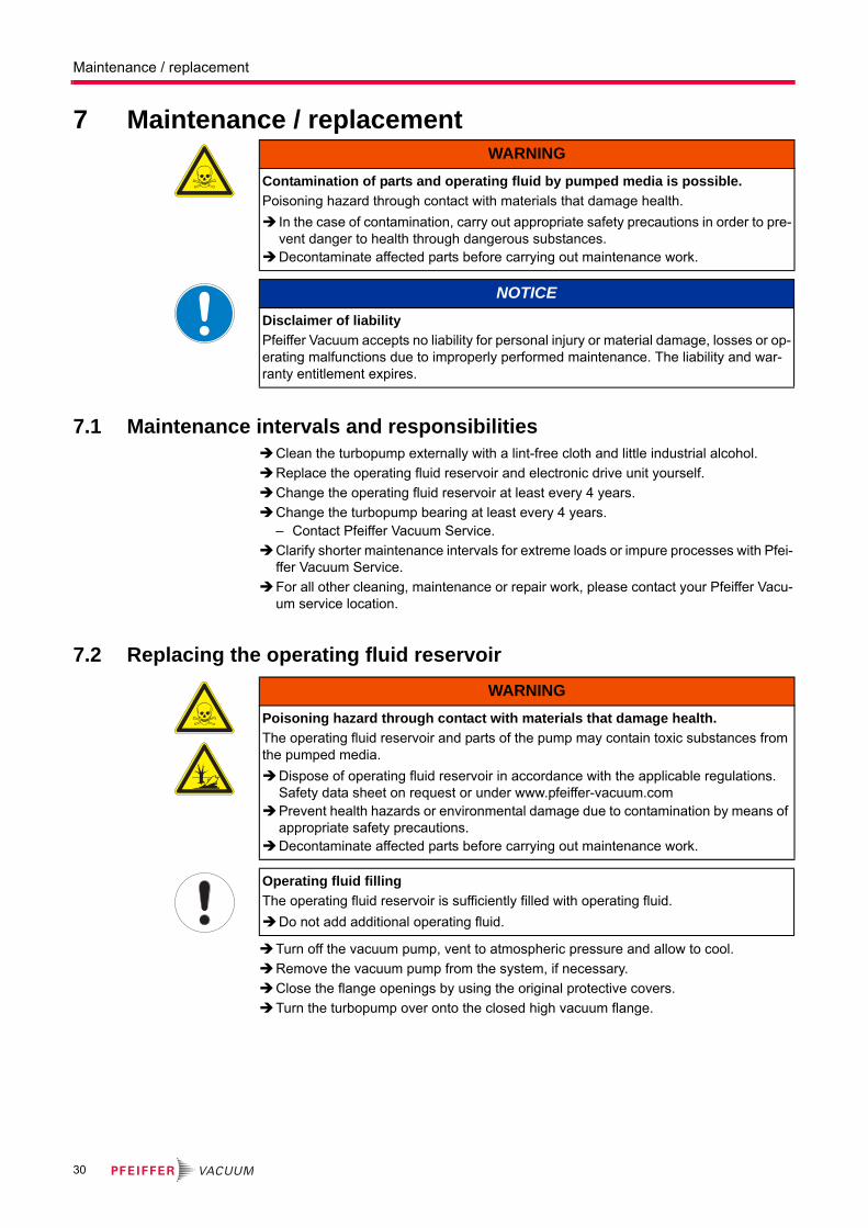
7 Maintenance / replacement
7.1 Maintenance intervals and responsibilitiesClean the turbopump externally with a lint-free cloth and little industrial alcohol.
Replace the operating fluid reservoir and electronic drive unit yourself.
Change the operating fluid reservoir at least every 4 years.
Change the turbopump bearing at least every 4 years.– Contact Pfeiffer Vacuum Service.
Clarify shorter maintenance intervals for extreme loads or impure processes with Pfei-ffer Vacuum Service.
For all other cleaning, maintenance or repair work, please contact your Pfeiffer Vacu-um service location.
7.2 Replacing the operating fluid reservoir
Turn off the vacuum pump, vent to atmospheric pressure and allow to cool.
Remove the vacuum pump from the system, if necessary.
Close the flange openings by using the original protective covers.
Turn the turbopump over onto the closed high vacuum flange.
WARNING
Contamination of parts and operating fluid by pumped media is possible.
Poisoning hazard through contact with materials that damage health.
In the case of contamination, carry out appropriate safety precautions in order to pre-vent danger to health through dangerous substances.
Decontaminate affected parts before carrying out maintenance work.
NOTICE
Disclaimer of liability
Pfeiffer Vacuum accepts no liability for personal injury or material damage, losses or op-erating malfunctions due to improperly performed maintenance. The liability and war-ranty entitlement expires.
WARNING
Poisoning hazard through contact with materials that damage health.
The operating fluid reservoir and parts of the pump may contain toxic substances from the pumped media.
Dispose of operating fluid reservoir in accordance with the applicable regulations. Safety data sheet on request or under www.pfeiffer-vacuum.com
Prevent health hazards or environmental damage due to contamination by means of appropriate safety precautions.
Decontaminate affected parts before carrying out maintenance work.
Operating fluid filling
The operating fluid reservoir is sufficiently filled with operating fluid.
Do not add additional operating fluid.
30

Maintenance / replacement
Screw out the Allen head screws (3x) from the end cover at the bottom of the tur-bopump.
Remove the end cover. Pay attention to the O-ring.
Remove the operating fluid reservoir out of the bearing cartridge.
Using tweezers, pull out the Poroplast rods (9x).
Remove impurities from the turbopump and the end cover with a clean, lint-free cloth. Do not use any cleaning fluids!
Using tweezers, insert the new Poroplast rods (9x).
Install the new operating fluid reservoir in the bearing mounting of the turbopump with the felt side oriented toward the nozzle tip.
For the HiPace turbopumps the operating fluid reservoir can be inserted completely into the bearing cartridge.
Screw in the end cover with the new O-ring.– Tightening torque: 2.5 Nm.
7.3 Replacing the electronic drive unit
Fig. 13: Assembly / Disassembly of the operating fluid reservoir
6 End cover7 Operating fluid reservoir
7a Poroplast rod15 Injection tip
55 Allen head screw73 O-ring
6
55
73
7
7a15
NOTICE
Damages to the pump and drive
Even after the mains power is switched off, the subsequently running pump delivers electric power to the electronic drive unit. There is a danger of electric body contact by premature separating the pump from the electronic drive unit.
Never separate the electronic drive unit from the pump when the mains power is con-nected or the rotor is running.
Operating parameters of the electronic drive unit
The factory operating parameters are always preset with replacement shipments.
The use of a HPU enables the storing and the reuse of an existing parameter record.Reset any individually changed application parameters.Refer to the manual "Electronic drive unit".
31

Maintenance / replacement
Do not exercise any mechanical load on the electronic drive unit.
Turn off the vacuum pump, vent to atmospheric pressure and allow to cool.
Only separate the pump and the electronic drive unit from each other after disconnect-ing the supply voltage and the complete standstill of the pump.
Remove the vacuum pump from the system, if necessary.
Unscrew Allen head screws (3x) from the electronic drive unit.
Pull the electronic drive unit off the pump.
Don’t touch any electrostatic sensitive devices.
Screw on and connect new electronic drive unit to the turbopump.– Tightening torque: 2.5 Nm.
7.3.1 Rotation speed set value
The typical nominal rotation speed of a turbopump is factory-set in the electronic drive unit. If the electronic drive unit is replaced or a different pump type is used, the reference set value of the nominal rotation speed must be confirmed. This procedure is part of a redundant safety system for avoiding excess rotation speeds.
Adjust the parameter [P:777] according to the pump type.
Alternatively: If no display and control unit is available, please use the "SpeedCon-figurator" of the spare parts delivery.
Fig. 14: Assembly / disassembly of the TC 400
8 Electronic drive unit 57 Allen head screw
857
HiPace Nominal rotation speed confirmation [P:777]300 1000 Hz
400 / 700 / 800 820 Hz
32
Decommissioning
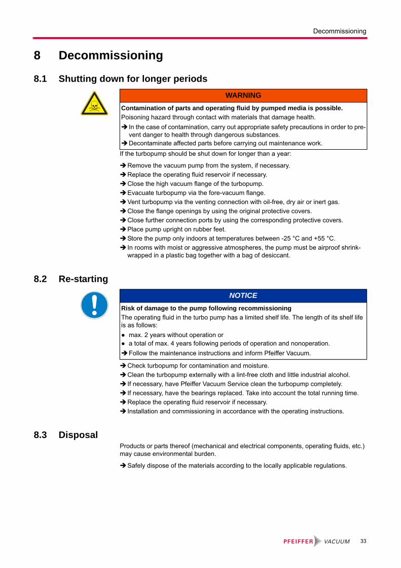
8 Decommissioning
8.1 Shutting down for longer periods
If the turbopump should be shut down for longer than a year:
Remove the vacuum pump from the system, if necessary.
Replace the operating fluid reservoir if necessary.
Close the high vacuum flange of the turbopump.
Evacuate turbopump via the fore-vacuum flange.
Vent turbopump via the venting connection with oil-free, dry air or inert gas.
Close the flange openings by using the original protective covers.
Close further connection ports by using the corresponding protective covers.
Place pump upright on rubber feet.
Store the pump only indoors at temperatures between -25 °C and +55 °C.
In rooms with moist or aggressive atmospheres, the pump must be airproof shrink-wrapped in a plastic bag together with a bag of desiccant.
8.2 Re-starting
Check turbopump for contamination and moisture.
Clean the turbopump externally with a lint-free cloth and little industrial alcohol.
If necessary, have Pfeiffer Vacuum Service clean the turbopump completely.
If necessary, have the bearings replaced. Take into account the total running time.
Replace the operating fluid reservoir if necessary.
Installation and commissioning in accordance with the operating instructions.
8.3 DisposalProducts or parts thereof (mechanical and electrical components, operating fluids, etc.) may cause environmental burden.
Safely dispose of the materials according to the locally applicable regulations.
WARNING
Contamination of parts and operating fluid by pumped media is possible.
Poisoning hazard through contact with materials that damage health.
In the case of contamination, carry out appropriate safety precautions in order to pre-vent danger to health through dangerous substances.
Decontaminate affected parts before carrying out maintenance work.
NOTICE
Risk of damage to the pump following recommissioning
The operating fluid in the turbo pump has a limited shelf life. The length of its shelf life is as follows:
● max. 2 years without operation or● a total of max. 4 years following periods of operation and nonoperation.
Follow the maintenance instructions and inform Pfeiffer Vacuum.
33
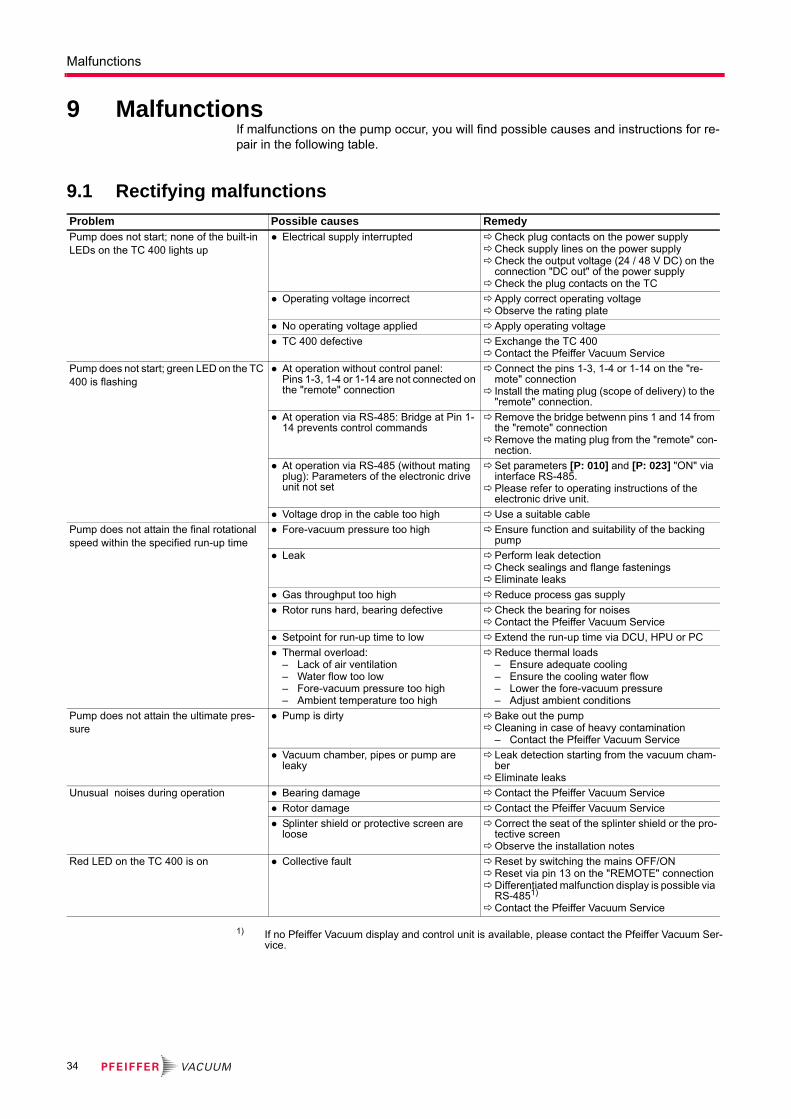
Malfunctions
9 MalfunctionsIf malfunctions on the pump occur, you will find possible causes and instructions for re-pair in the following table.
9.1 Rectifying malfunctions
1) If no Pfeiffer Vacuum display and control unit is available, please contact the Pfeiffer Vacuum Ser-vice.
Problem Possible causes RemedyPump does not start; none of the built-in LEDs on the TC 400 lights up
● Electrical supply interrupted Check plug contacts on the power supplyCheck supply lines on the power supplyCheck the output voltage (24 / 48 V DC) on the
connection "DC out" of the power supplyCheck the plug contacts on the TC
● Operating voltage incorrect Apply correct operating voltageObserve the rating plate
● No operating voltage applied Apply operating voltage
● TC 400 defective Exchange the TC 400Contact the Pfeiffer Vacuum Service
Pump does not start; green LED on the TC 400 is flashing
● At operation without control panel: Pins 1-3, 1-4 or 1-14 are not connected on the "remote" connection
Connect the pins 1-3, 1-4 or 1-14 on the "re-mote" connection
Install the mating plug (scope of delivery) to the "remote" connection.
● At operation via RS-485: Bridge at Pin 1-14 prevents control commands
Remove the bridge betwenn pins 1 and 14 from the "remote" connection
Remove the mating plug from the "remote" con-nection.
● At operation via RS-485 (without mating plug): Parameters of the electronic drive unit not set
Set parameters [P: 010] and [P: 023] "ON" via interface RS-485.
Please refer to operating instructions of the electronic drive unit.
● Voltage drop in the cable too high Use a suitable cable
Pump does not attain the final rotational speed within the specified run-up time
● Fore-vacuum pressure too high Ensure function and suitability of the backing pump
● Leak Perform leak detectionCheck sealings and flange fasteningsEliminate leaks
● Gas throughput too high Reduce process gas supply
● Rotor runs hard, bearing defective Check the bearing for noisesContact the Pfeiffer Vacuum Service
● Setpoint for run-up time to low Extend the run-up time via DCU, HPU or PC
● Thermal overload:– Lack of air ventilation– Water flow too low– Fore-vacuum pressure too high– Ambient temperature too high
Reduce thermal loads– Ensure adequate cooling– Ensure the cooling water flow– Lower the fore-vacuum pressure– Adjust ambient conditions
Pump does not attain the ultimate pres-sure
● Pump is dirty Bake out the pumpCleaning in case of heavy contamination
– Contact the Pfeiffer Vacuum Service
● Vacuum chamber, pipes or pump are leaky
Leak detection starting from the vacuum cham-ber
Eliminate leaks
Unusual noises during operation ● Bearing damage Contact the Pfeiffer Vacuum Service
● Rotor damage Contact the Pfeiffer Vacuum Service
● Splinter shield or protective screen are loose
Correct the seat of the splinter shield or the pro-tective screen
Observe the installation notes
Red LED on the TC 400 is on ● Collective fault Reset by switching the mains OFF/ONReset via pin 13 on the "REMOTE" connectionDifferentiated malfunction display is possible via
RS-4851)
Contact the Pfeiffer Vacuum Service
34

Service
10 ServicePfeiffer Vacuum offers first-class service!
● Operating fluid and bearing change on the spot by Pfeiffer Vacuum FieldService
● Maintenance / repair in the nearby ServiceCenter or ServicePoint
● Fast replacement with exchange products in mint condition
● Advice on the most cost-efficient and quickest solution
Detailed information, addresses and forms at: www.pfeiffer-vacuum.com (Service).
Maintenance and repair in the Pfeiffer Vacuum ServiceCenter
The following steps are necessary to ensure a fast, smooth servicing process:
Download the forms "Service Request" and "Declaration on Contamination".1)
Fill out the "Service Request" form and send it by fax or e-mail to your Pfeiffer Vacuum service address.
Include the confirmation on the service request from Pfeiffer Vacuum with your ship-ment.
Fill out the declaration on contamination and include it in the shipment (required!).
Dismantle all accessories.
Drain the operating fluid (applies for turbopumps with pumping speed > 800 l/s).
Leave electronic drive on the pump.
Close the flange openings by using the original protective covers.
If possible, send pump or unit in the original packaging.
Sending of contaminated pumps or devices
No units will be accepted if they are contaminated with micro-biological, explosive or ra-dioactive substances. “Hazardous substances” are substances and compounds in ac-cordance with the hazardous goods directive (current version). If pumps are contaminat-ed or the declaration on contamination is missing, Pfeiffer Vacuum performs decontamination at the shipper's expense.
Neutralise the pump by flushing it with nitrogen or dry air.
Close all openings airtight.
Seal the pump or unit in suitable protective film.
Return the pump/unit only in a suitable and sturdy transport container and send it in while following applicable transport conditions.
Exchange unit
The factory operating parameters are always preset with exchange units. If you use changed parameters for your application, you have to set these again.
Service orders
All service orders are carried out exclusively according to our repair conditions for vacu-um units and components.
1) Forms under www.pfeiffer-vacuum.com
35

Spare parts HiPace 300
11 Spare parts HiPace 300
Please also specify model number of the the rating plate when ordering accessories or spare parts.
Item Designation Order number Notes Pieces Order qty.7 Operating fluid reservoir PM 143 451 -T incl. Poroplast rods 1
8 Electronic drive unit TC 400 according to the rating plate depends on the connection panel 1
14 Swiveling screw-fitting P 4131 007 D water cooling 2
93 Mating plug "remote" PM 061 378 -X with bridges 1
87
14
36
Accessories
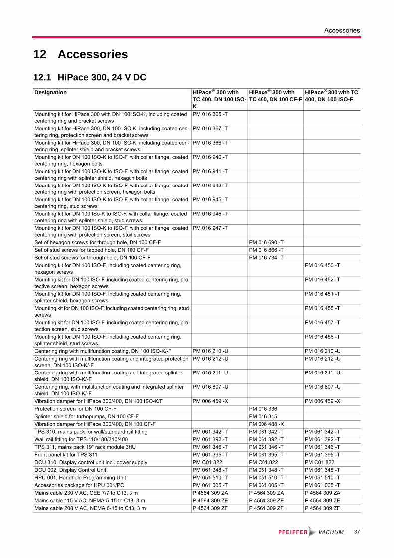
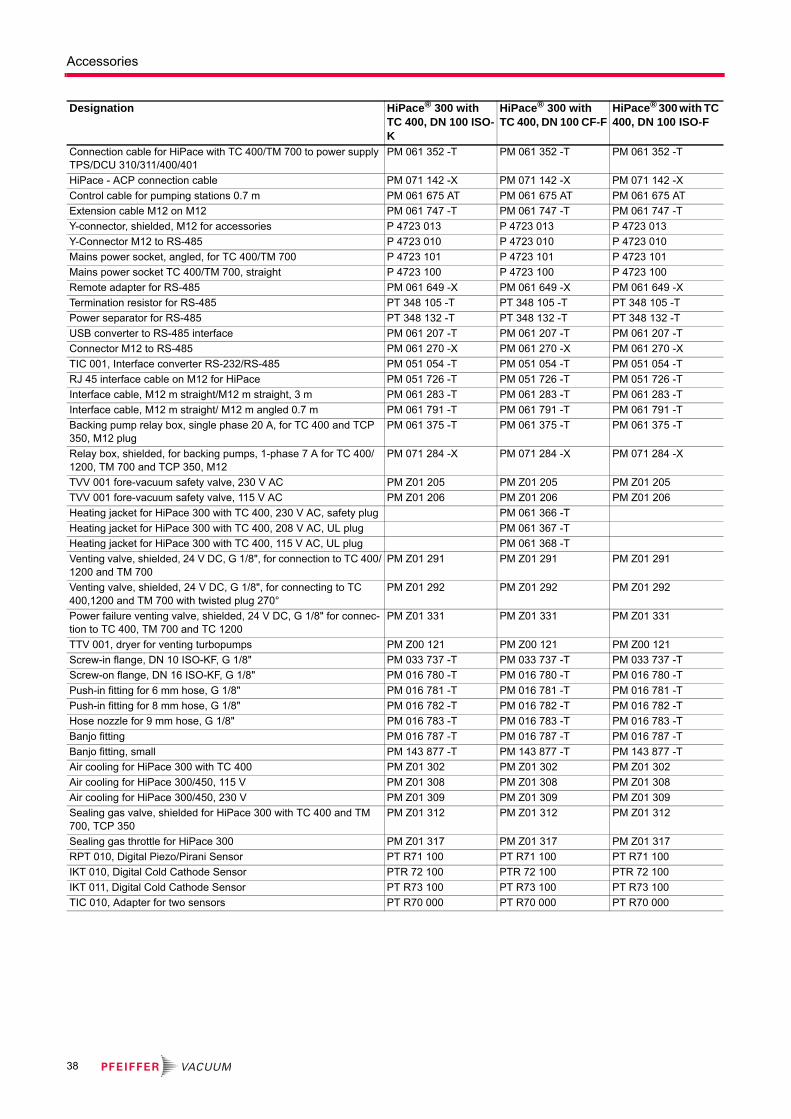
12 Accessories
12.1 HiPace 300, 24 V DC
Designation HiPace® 300 with TC 400, DN 100 ISO-K
HiPace® 300 with TC 400, DN 100 CF-F
HiPace® 300 with TC 400, DN 100 ISO-F
Mounting kit for HiPace 300 with DN 100 ISO-K, including coated centering ring and bracket screws
PM 016 365 -T
Mounting kit for HiPace 300, DN 100 ISO-K, including coated cen-tering ring, protection screen and bracket screws
PM 016 367 -T
Mounting kit for HiPace 300, DN 100 ISO-K, including coated cen-tering ring, splinter shield and bracket screws
PM 016 366 -T
Mounting kit for DN 100 ISO-K to ISO-F, with collar flange, coated centering ring, hexagon bolts
PM 016 940 -T
Mounting kit for DN 100 ISO-K to ISO-F, with collar flange, coated centering ring with splinter shield, hexagon bolts
PM 016 941 -T
Mounting kit for DN 100 ISO-K to ISO-F, with collar flange, coated centering ring with protection screen, hexagon bolts
PM 016 942 -T
Mounting kit for DN 100 ISO-K to ISO-F, with collar flange, coated centering ring, stud screws
PM 016 945 -T
Mounting kit for DN 100 ISo-K to ISO-F, with collar flange, coated centering ring with splinter shield, stud screws
PM 016 946 -T
Mounting kit for DN 100 ISO-K to ISO-F, with collar flange, coated centering ring with protection screen, stud screws
PM 016 947 -T
Set of hexagon screws for through hole, DN 100 CF-F PM 016 690 -T
Set of stud screws for tapped hole, DN 100 CF-F PM 016 866 -T
Set of stud screws for through hole, DN 100 CF-F PM 016 734 -T
Mounting kit for DN 100 ISO-F, including coated centering ring, hexagon screws
PM 016 450 -T
Mounting kit for DN 100 ISO-F, including coated centering ring, pro-tective screen, hexagon screws
PM 016 452 -T
Mounting kit for DN 100 ISO-F, including coated centering ring, splinter shield, hexagon screws
PM 016 451 -T
Mounting kit for DN 100 ISO-F, including coated centering ring, stud screws
PM 016 455 -T
Mounting kit for DN 100 ISO-F, including coated centering ring, pro-tection screen, stud screws
PM 016 457 -T
Mounting kit for DN 100 ISO-F, including coated centering ring, splinter shield, stud screws
PM 016 456 -T
Centering ring with multifunction coating, DN 100 ISO-K/-F PM 016 210 -U PM 016 210 -U
Centering ring with multifunction coating and integrated protection screen, DN 100 ISO-K/-F
PM 016 212 -U PM 016 212 -U
Centering ring with multifunction coating and integrated splinter shield, DN 100 ISO-K/-F
PM 016 211 -U PM 016 211 -U
Centering ring, with multifunction coating and integrated splinter shield, DN 100 ISO-K/-F
PM 016 807 -U PM 016 807 -U
Vibration damper for HiPace 300/400, DN 100 ISO-K/F PM 006 459 -X PM 006 459 -X
Protection screen for DN 100 CF-F PM 016 336
Splinter shield for turbopumps, DN 100 CF-F PM 016 315
Vibration damper for HiPace 300/400, DN 100 CF-F PM 006 488 -X
TPS 310, mains pack for wall/standard rail fitting PM 061 342 -T PM 061 342 -T PM 061 342 -T
Wall rail fitting for TPS 110/180/310/400 PM 061 392 -T PM 061 392 -T PM 061 392 -T
TPS 311, mains pack 19" rack module 3HU PM 061 346 -T PM 061 346 -T PM 061 346 -T
Front panel kit for TPS 311 PM 061 395 -T PM 061 395 -T PM 061 395 -T
DCU 310, Display control unit incl. power supply PM C01 822 PM C01 822 PM C01 822
DCU 002, Display Control Unit PM 061 348 -T PM 061 348 -T PM 061 348 -T
HPU 001, Handheld Programming Unit PM 051 510 -T PM 051 510 -T PM 051 510 -T
Accessories package for HPU 001/PC PM 061 005 -T PM 061 005 -T PM 061 005 -T
Mains cable 230 V AC, CEE 7/7 to C13, 3 m P 4564 309 ZA P 4564 309 ZA P 4564 309 ZA
Mains cable 115 V AC, NEMA 5-15 to C13, 3 m P 4564 309 ZE P 4564 309 ZE P 4564 309 ZE
Mains cable 208 V AC, NEMA 6-15 to C13, 3 m P 4564 309 ZF P 4564 309 ZF P 4564 309 ZF
37
Accessories
Connection cable for HiPace with TC 400/TM 700 to power supply TPS/DCU 310/311/400/401
PM 061 352 -T PM 061 352 -T PM 061 352 -T
HiPace - ACP connection cable PM 071 142 -X PM 071 142 -X PM 071 142 -X
Control cable for pumping stations 0.7 m PM 061 675 AT PM 061 675 AT PM 061 675 AT
Extension cable M12 on M12 PM 061 747 -T PM 061 747 -T PM 061 747 -T
Y-connector, shielded, M12 for accessories P 4723 013 P 4723 013 P 4723 013
Y-Connector M12 to RS-485 P 4723 010 P 4723 010 P 4723 010
Mains power socket, angled, for TC 400/TM 700 P 4723 101 P 4723 101 P 4723 101
Mains power socket TC 400/TM 700, straight P 4723 100 P 4723 100 P 4723 100
Remote adapter for RS-485 PM 061 649 -X PM 061 649 -X PM 061 649 -X
Termination resistor for RS-485 PT 348 105 -T PT 348 105 -T PT 348 105 -T
Power separator for RS-485 PT 348 132 -T PT 348 132 -T PT 348 132 -T
USB converter to RS-485 interface PM 061 207 -T PM 061 207 -T PM 061 207 -T
Connector M12 to RS-485 PM 061 270 -X PM 061 270 -X PM 061 270 -X
TIC 001, Interface converter RS-232/RS-485 PM 051 054 -T PM 051 054 -T PM 051 054 -T
RJ 45 interface cable on M12 for HiPace PM 051 726 -T PM 051 726 -T PM 051 726 -T
Interface cable, M12 m straight/M12 m straight, 3 m PM 061 283 -T PM 061 283 -T PM 061 283 -T
Interface cable, M12 m straight/ M12 m angled 0.7 m PM 061 791 -T PM 061 791 -T PM 061 791 -T
Backing pump relay box, single phase 20 A, for TC 400 and TCP 350, M12 plug
PM 061 375 -T PM 061 375 -T PM 061 375 -T
Relay box, shielded, for backing pumps, 1-phase 7 A for TC 400/1200, TM 700 and TCP 350, M12
PM 071 284 -X PM 071 284 -X PM 071 284 -X
TVV 001 fore-vacuum safety valve, 230 V AC PM Z01 205 PM Z01 205 PM Z01 205
TVV 001 fore-vacuum safety valve, 115 V AC PM Z01 206 PM Z01 206 PM Z01 206
Heating jacket for HiPace 300 with TC 400, 230 V AC, safety plug PM 061 366 -T
Heating jacket for HiPace 300 with TC 400, 208 V AC, UL plug PM 061 367 -T
Heating jacket for HiPace 300 with TC 400, 115 V AC, UL plug PM 061 368 -T
Venting valve, shielded, 24 V DC, G 1/8", for connection to TC 400/1200 and TM 700
PM Z01 291 PM Z01 291 PM Z01 291
Venting valve, shielded, 24 V DC, G 1/8", for connecting to TC 400,1200 and TM 700 with twisted plug 270°
PM Z01 292 PM Z01 292 PM Z01 292
Power failure venting valve, shielded, 24 V DC, G 1/8" for connec-tion to TC 400, TM 700 and TC 1200
PM Z01 331 PM Z01 331 PM Z01 331
TTV 001, dryer for venting turbopumps PM Z00 121 PM Z00 121 PM Z00 121
Screw-in flange, DN 10 ISO-KF, G 1/8" PM 033 737 -T PM 033 737 -T PM 033 737 -T
Screw-on flange, DN 16 ISO-KF, G 1/8" PM 016 780 -T PM 016 780 -T PM 016 780 -T
Push-in fitting for 6 mm hose, G 1/8" PM 016 781 -T PM 016 781 -T PM 016 781 -T
Push-in fitting for 8 mm hose, G 1/8" PM 016 782 -T PM 016 782 -T PM 016 782 -T
Hose nozzle for 9 mm hose, G 1/8" PM 016 783 -T PM 016 783 -T PM 016 783 -T
Banjo fitting PM 016 787 -T PM 016 787 -T PM 016 787 -T
Banjo fitting, small PM 143 877 -T PM 143 877 -T PM 143 877 -T
Air cooling for HiPace 300 with TC 400 PM Z01 302 PM Z01 302 PM Z01 302
Air cooling for HiPace 300/450, 115 V PM Z01 308 PM Z01 308 PM Z01 308
Air cooling for HiPace 300/450, 230 V PM Z01 309 PM Z01 309 PM Z01 309
Sealing gas valve, shielded for HiPace 300 with TC 400 and TM 700, TCP 350
PM Z01 312 PM Z01 312 PM Z01 312
Sealing gas throttle for HiPace 300 PM Z01 317 PM Z01 317 PM Z01 317
RPT 010, Digital Piezo/Pirani Sensor PT R71 100 PT R71 100 PT R71 100
IKT 010, Digital Cold Cathode Sensor PTR 72 100 PTR 72 100 PTR 72 100
IKT 011, Digital Cold Cathode Sensor PT R73 100 PT R73 100 PT R73 100
TIC 010, Adapter for two sensors PT R70 000 PT R70 000 PT R70 000
Designation HiPace® 300 with TC 400, DN 100 ISO-K
HiPace® 300 with TC 400, DN 100 CF-F
HiPace® 300 with TC 400, DN 100 ISO-F
38

Accessories
12.2 Differences at HiPace 300, 48 V DC
Designation HiPace® 300 with TC 400, DN 100 ISO-K
HiPace® 300 with TC 400, DN 100 CF-F
HiPace® 300 with TC 400, DN 100 ISO-F
TPS 400, power supply 48 V DC, for wall/standard rail fitting PM 061 343 -T PM 061 343 -T PM 061 343 -T
TPS 401, power supply 48 V DC, 19" partial plug-in 3HU PM 061 347 -T PM 061 347 -T PM 061 347 -T
Front panel kit for TPS 401 PM 061 396 -T PM 061 396 -T PM 061 396 -T
DCU 400, Display control unit incl. power supply PM C01 823 PM C01 823 PM C01 823
39
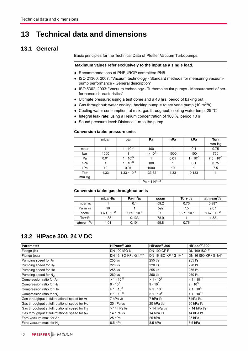
Technical data and dimensions
13 Technical data and dimensions
13.1 GeneralBasic principles for the Technical Data of Pfeiffer Vacuum Turbopumps:
● Recommendations of PNEUROP committee PN5
● ISO 21360; 2007: "Vacuum technology - Standard methods for measuring vacuum-pump performance - General description"
● ISO 5302; 2003: "Vacuum technology - Turbomolecular pumps - Measurement of per-formance characteristics"
● Ultimate pressure: using a test dome and a 48 hrs. period of baking out
● Gas throughput: water cooling; backing pump = rotary vane pump (10 m3/h)
● Cooling water consumption: at max. gas throughput, cooling water temp. 25 °C
● Integral leak rate: using a Helium concentration of 100 %, period 10 s
● Sound pressure level: Distance 1 m to the pump
Conversion table: pressure units
Conversion table: gas throughput units
13.2 HiPace 300, 24 V DC
Maximum values refer exclusively to the input as a single load.
mbar bar Pa hPa kPa Torrmm Hg
mbar 1 1 · 10-3 100 1 0.1 0.75
bar 1000 1 1 · 105 1000 100 750
Pa 0.01 1 · 10-5 1 0.01 1 · 10-3 7.5 · 10-3
hPa 1 1 · 10-3 100 1 0.1 0.75
kPa 10 0.01 1000 10 1 7.5
Torr mm Hg
1.33 1.33 · 10-3 133.32 1.33 0.133 1
1 Pa = 1 N/m2
mbar·l/s Pa·m3/s sccm Torr·l/s atm·cm3/s mbar·l/s 1 0.1 59.2 0.75 0.987
Pa·m3/s 10 1 592 7.5 9.87
sccm 1.69 · 10-2 1.69 · 10-3 1 1.27 · 10-2 1.67 · 10-2
Torr·l/s 1.33 0.133 78.9 1 1.32
atm·cm3/s 1.01 0.101 59.8 0.76 1
Parameter HiPace® 300 HiPace® 300 HiPace® 300Flange (in) DN 100 ISO-K DN 100 CF-F DN 100 ISO-F
Flange (out) DN 16 ISO-KF / G 1/4" DN 16 ISO-KF / G 1/4" DN 16 ISO-KF / G 1/4"
Pumping speed for Ar 255 l/s 255 l/s 255 l/s
Pumping speed for H2 220 l/s 220 l/s 220 l/s
Pumping speed for He 255 l/s 255 l/s 255 l/s
Pumping speed for N2 260 l/s 260 l/s 260 l/s
Compression ratio for Ar > 1 · 1011 > 1 · 1011 > 1 · 1011
Compression ratio for H2 9 · 105 9 · 105 9 · 105
Compression ratio for He > 1 · 108 > 1 · 108 > 1 · 108
Compression ratio for N2 > 1 · 1011 > 1 · 1011 > 1 · 1011
Gas throughput at full rotational speed for Ar 7 hPa l/s 7 hPa l/s 7 hPa l/s
Gas throughput at full rotational speed for He 20 hPa l/s 20 hPa l/s 20 hPa l/s
Gas throughput at full rotational speed for H2 > 14 hPa l/s > 14 hPa l/s > 14 hPa l/s
Gas throughput at full rotational speed for N2 14 hPa l/s 14 hPa l/s 14 hPa l/s
Fore-vacuum max. for Ar 25 hPa 25 hPa 25 hPa
Fore-vacuum max. for H2 8.5 hPa 8.5 hPa 8.5 hPa
40
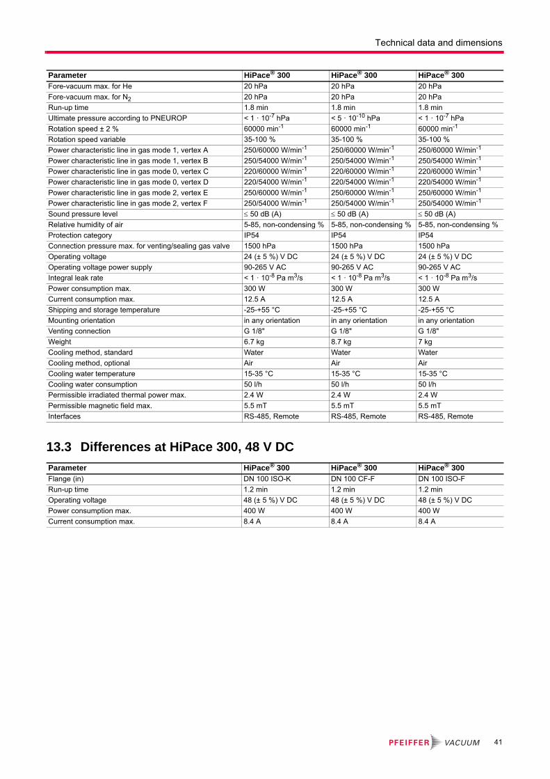
Technical data and dimensions
13.3 Differences at HiPace 300, 48 V DC
Fore-vacuum max. for He 20 hPa 20 hPa 20 hPa
Fore-vacuum max. for N2 20 hPa 20 hPa 20 hPa
Run-up time 1.8 min 1.8 min 1.8 min
Ultimate pressure according to PNEUROP < 1 · 10-7 hPa < 5 · 10-10 hPa < 1 · 10-7 hPa
Rotation speed ± 2 % 60000 min-1 60000 min-1 60000 min-1
Rotation speed variable 35-100 % 35-100 % 35-100 %
Power characteristic line in gas mode 1, vertex A 250/60000 W/min-1 250/60000 W/min-1 250/60000 W/min-1
Power characteristic line in gas mode 1, vertex B 250/54000 W/min-1 250/54000 W/min-1 250/54000 W/min-1
Power characteristic line in gas mode 0, vertex C 220/60000 W/min-1 220/60000 W/min-1 220/60000 W/min-1
Power characteristic line in gas mode 0, vertex D 220/54000 W/min-1 220/54000 W/min-1 220/54000 W/min-1
Power characteristic line in gas mode 2, vertex E 250/60000 W/min-1 250/60000 W/min-1 250/60000 W/min-1
Power characteristic line in gas mode 2, vertex F 250/54000 W/min-1 250/54000 W/min-1 250/54000 W/min-1
Sound pressure level 50 dB (A) 50 dB (A) 50 dB (A)
Relative humidity of air 5-85, non-condensing % 5-85, non-condensing % 5-85, non-condensing %
Protection category IP54 IP54 IP54
Connection pressure max. for venting/sealing gas valve 1500 hPa 1500 hPa 1500 hPa
Operating voltage 24 (± 5 %) V DC 24 (± 5 %) V DC 24 (± 5 %) V DC
Operating voltage power supply 90-265 V AC 90-265 V AC 90-265 V AC
Integral leak rate < 1 · 10-8 Pa m3/s < 1 · 10-8 Pa m3/s < 1 · 10-8 Pa m3/s
Power consumption max. 300 W 300 W 300 W
Current consumption max. 12.5 A 12.5 A 12.5 A
Shipping and storage temperature -25-+55 °C -25-+55 °C -25-+55 °C
Mounting orientation in any orientation in any orientation in any orientation
Venting connection G 1/8" G 1/8" G 1/8"
Weight 6.7 kg 8.7 kg 7 kg
Cooling method, standard Water Water Water
Cooling method, optional Air Air Air
Cooling water temperature 15-35 °C 15-35 °C 15-35 °C
Cooling water consumption 50 l/h 50 l/h 50 l/h
Permissible irradiated thermal power max. 2.4 W 2.4 W 2.4 W
Permissible magnetic field max. 5.5 mT 5.5 mT 5.5 mT
Interfaces RS-485, Remote RS-485, Remote RS-485, Remote
Parameter HiPace® 300 HiPace® 300 HiPace® 300
Parameter HiPace® 300 HiPace® 300 HiPace® 300Flange (in) DN 100 ISO-K DN 100 CF-F DN 100 ISO-F
Run-up time 1.2 min 1.2 min 1.2 min
Operating voltage 48 (± 5 %) V DC 48 (± 5 %) V DC 48 (± 5 %) V DC
Power consumption max. 400 W 400 W 400 W
Current consumption max. 8.4 A 8.4 A 8.4 A
41

Technical data and dimensions
13.4 Dimensions
Fig. 15: HiPace 300, DN 100 ISO-K
Fig. 16: HiPace 300, DN 100 CF-F
Fig. 17: HiPace 300, DN 100 ISO-F
13
1
19
5
13
1
16
2
Ø110
45°45°
M8 (5x)
83
2.6
118
18.6
20°
Ø1
44
13
0
18
416
3
VV DN 16 ISO-KF
HVDN 100 ISO-K
Ø8
90°
°
190
13
1
20
7
14
3
17
4
45°45°
M8 (5x)
83
2.6°
118
18.620°
Ø 1
44
13
0
19
617
5
VV DN 16 ISO-KF
Ø 8
90°
HVDN 100 CF-F
13
1
19
5
13
1
16
2
45°45°
M8 (5x)
83
2.6°
118
18.6
20°
Ø 1
44
13
0
18
416
3
VV DN 16 ISO-KF
HVDN 100 ISO-F
Ø 8
90°
42
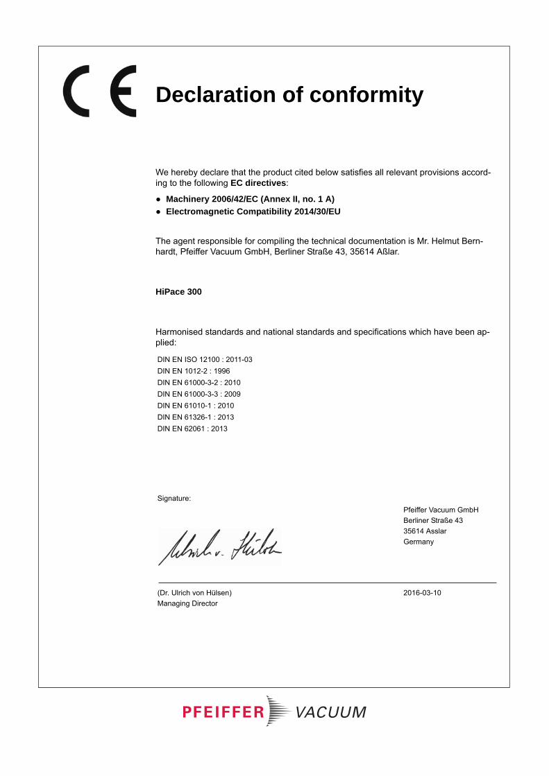
Declaration of conformity
We hereby declare that the product cited below satisfies all relevant provisions accord-ing to the following EC directives:
● Machinery 2006/42/EC (Annex II, no. 1 A)
● Electromagnetic Compatibility 2014/30/EU
The agent responsible for compiling the technical documentation is Mr. Helmut Bern-hardt, Pfeiffer Vacuum GmbH, Berliner Straße 43, 35614 Aßlar.
HiPace 300
Harmonised standards and national standards and specifications which have been ap-plied:
DIN EN ISO 12100 : 2011-03
DIN EN 1012-2 : 1996
DIN EN 61000-3-2 : 2010
DIN EN 61000-3-3 : 2009
DIN EN 61010-1 : 2010
DIN EN 61326-1 : 2013
DIN EN 62061 : 2013
Signature:
Pfeiffer Vacuum GmbH
Berliner Straße 43
35614 Asslar
Germany
(Dr. Ulrich von Hülsen)
Managing Director
2016-03-10

VACUUM SOLUTIONS FROM A SINGLE SOURCEPfeiffer Vacuum stands for innovative and custom vacuum solutions worldwide,
technological perfection, competent advice and reliable service.
COMPLETE RANGE OF PRODUCTSFrom a single component to complex systems:
We are the only supplier of vacuum technology that provides a complete product portfolio.
COMPETENCE IN THEORY AND PRACTICEBenefit from our know-how and our portfolio of training opportunities!
We support you with your plant layout and provide first-class on-site service worldwide.
Are you looking for a
perfect vacuum solution?
Please contact us:
Pfeiffer Vacuum GmbH
Headquarters • Germany
T +49 6441 802-0
www.pfeiffer-vacuum.com


