17
Operating Instructions for Authorized Experts Light Oil Burners EK 5... L-RO 09/2001 123.697 Designs: DIN TRD
Operating Instructionsfor Authorized Experts
Light Oil BurnersEK 5... L-RO
09/2001 123.697
Designs:DINTRD
2
Inhalt
Survey Technical DataPerformance Chart ............................................................................... 3
Survey Dimensions .......................................................................................... 4Dimensiones Sliding Flange Versions ....................................................................... 5Burner Functions Functional Description
Functional Diagram .............................................................................. 6Burner Functions Functional Sequence of Burner Control Units LAL 1…
RWF 40 ................................................................................................ 7Installation Mounting the Burner to the Heat Generator
Elektrical Connection ........................................................................... 8Installation Oil Connection
Supply Oil RegulationStart-Up ................................................................................................ 9
Start-Up Burner Head SettingDimensiones ...................................................................................... 10
Start-up Return Nozzle Rod RDN .................................................................... 11Start-up Nozzle Selection, Typ W-50° ............................................................. 12Adjustments Air Regulation ..................................................................................... 13Adjustments Return Oil Regulation
Oil Pressure Monitor .......................................................................... 14Adjustments Adjusting the Limit Switches
at the Electric Servomotor .................................................................. 15Service-Instructions Maintenance
Troubleshooting ................................................................................. 16
Survey
Table of ContensGeneral Information
General information
The EK5 ... L-RO series of ELCO light oil burners is designed for the combu-stion of extra-light fuel oil.7KHLU�GHVLJQ�DQG�SHUIRUPDQFH�FRPSO\�ZLWK�FXUUHQWO\�DSSOLFDEOH�JXLGHOLQHV�DQG�UHJXODWLRQV��,QVWDOODWLRQ�DQG�VWDUW�XS�RI�WKH�EXUQHU�PXVW�EH�SHUIRUPHG�E\�D�TXD�OLILHG�H[SHUW�ZKR�LV�UHVSRQVLEOH�IRU�WKH�SURSHU�H[HFXWLRQ�RI�WKHVH�WDVNV��2EVHUYH�WKH�UHOHYDQW�VWDQGDUGV�WR�HQVXUH�VDIH��HQYLURQPHQWDOO\�IULHQGO\�DQG�HQHUJ\�VDYLQJ�RSHUDWLRQ�RI�WKH�EXU�QHU��
%XUQHU�GHVFULSWLRQ�7KH�PRQREORF�EXUQHUV�IHDWXUH�IXOO\�DXWRPDWLF�PRGXODWLQJ�FRQWURO��7KH\�DUH�VXLWDEOH�IRU�FRQQHFWLRQ�WR�DOO�VWDQGDUG�KHDW�JHQHUDWRUV�ZLWKLQ�WKHLU�SHUIRU�PDQFH�UDQJH��&RQVWUXFWLRQ�DQG�SHUIRU�PDQFH�RI�WKH�EXUQHU�FRPSO\�ZLWK�WKH�(1�VWDQGDUG������
6LWH�RI�LQVWDOODWLRQ�7KH�EXUQHU�PXVW�QRW�EH�RSHUDWHG�LQ�URRPV�ZLWK�DJJUHVVLYH�IXPHV��GXVW�ODGHQ�DLU�RU�KLJK�DWPRVSKHULF�KXPLGLW\�
(/&2�UHMHFWV�DOO�ZDUUDQW\�FODLPV�IRU�GDPDJH�UHVXOWLQJ�IURP�RQH�RI�WKH�IROORZLQJ�UHDVRQV��
� ,PSURSHU�XVH�� ,QH[SHUW�LQVWDOODWLRQ�RU�PDLQWHQDQFH�E\�WKH�SXUFKDVHU�RU�WKLUG�SHUVRQV��LQFOXGLQJ�WKH�LQVWDOODWLRQ�RI�SDUWV�RWKHU�WKDQ�JHQXLQH�SDUWV�VXSSOLHG�E\�WKH�PDQXIDFWXUHU����
6WDUW�XS�,QLWLDO�VWDUW�XS�RI�WKH�RLO�EXUQLQJ�LQVWDOOD�WLRQ�PXVW�EH�SHUIRUPHG�E\�WKH�LQVWDOOHU��PDQXIDFWXUHU��RU�E\�DQRWKHU�H[SHUW�GHVL�JQDWHG�E\�WKHP��
'HOLYHU\�DQG�2SHUDWLQJ�,QVWUXFWLRQV�$W�WKH�WLPH�RI�GHOLYHU\�DW�WKH�ODWHVW��WKH�PDQXIDFWXUHU�RI�WKH�RLO�EXUQHU�PXVW�VXS�SO\�WKH�XVHU�ZLWK�D�VHW�RI�2SHUDWLQJ�DQG�6HUYLFH�,QVWUXFWLRQV��7KHVH�VKRXOG�EH�NHSW�LQ�WKH�URRP�ZKHUH�WKH�KHDWLQJ�XQLW�LV�LQVWDOOHG��7KH�DGGUHVV�DQG�WHOHSKRQH�QXPEHU�RI�WKH�QHDUHVW�VHUYLFH�UHSUHVHQWDWLYH�PXVW�EH�HQWHUHG�LQ�WKH�,QVWUXFWLRQV�
1RWH�IRU�WKH�XVHU�7KH�V\VWHP�VKRXOG�EH�VHUYLFHG�E\�DQ�H[SHUW�DW�OHDVW�RQFH�D�\HDU��7R�HQVXUH�PDLQWHQDQFH�DO�UHJXODU�LQWHUYDOV��ZH�UHFRPPHQG�\RX�WR�FRQFOXGH�D�VHUYLFH�FRQWUDFW��
6FRSH�RI�GHOLYHU\�(DFK�EXUQHU�LV�GHOLYHUHG�LQ�D�VHSDUDWH�SDFNLQJ�FDVH��7KH�IROORZLQJ�FRPSRQ�HQWV�DUH�LQFOXGHG�LQ�GHOLYHU\��� Burner with burner head, fixed
mounting flange and insulating base � Two oil tubes � Automatic burner control unit with
plug- in socket
3
Survey
Technical DataPerformance Chart
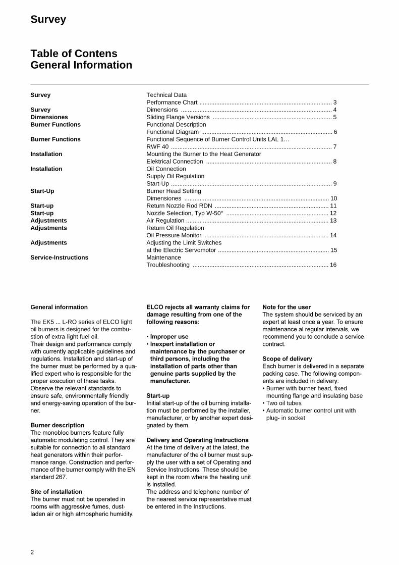
Performance charts
The performance charts reflect the values approved during official homo-logation.
Determining the required thermal out-put:
QF = Thermal output (kW)QN = Rated boiler capacity (kW)ηK = Boiler efficiency (%)
Burner type EK 5.180 L-RO EK 5.220 L-RO EK 5.280 L-RO
Technical DataThermal output min 500 kW 855 kW 900 kWThermal output max. 1780 kW 2135 kW 2730 kWOil flow min 42 kg/h 72 kg/h 80 kg/hOil flow max. 150 kg/h 180 kg/h 230 kg/hFuel oil EL, DIN 51603 EL, DIN 51603 EL, DIN 51603Hydraulic system modulating return nozzle return nozzle return nozzleAir regulation suction side Air cut-off valve Air cut-off valve Air cut-off valveAir regulation pressure side in burner head OAS* in burner head OAS* in burner head OAS*Control ratio max. 33 / 100% 33 / 100% 33 / 100%Voltage 230/400 V, 50 Hz 230/400 V, 50 Hz 400/690 V, 50 HzPower consumption 4,7 kW 4,7 kW 6,5 kWWeight approx. 125 kg 130 kg 160 kg* OAS = Optimized Air Speed
Burner equipment
Electric motor 2800 min.-1 4,0 kW 4,0 kW 5,5 kW
Automatic burner control unit LAL 1.25 LAL 1.25 LAL 1.25Controller RWF 32 RWF 32 RWF 32Flame monitor QRB 3 QRB 3 QRB 3Ignition transformer ZM 20/14 ZM 20/14 ZM 20/14Solenoid valves Nozzle control 2-way 2-way 2-wayAir damper drive EA 2, electr. EA 2, electr. EA 2, electr.Oil pressure pump NVBGR 400 l/h / TA2 NVBGR 600 l/h / TA3 NVBGR 600 l/h TA3Oil pressure monitor DSA 43 F001 DSA 43 F001 DSA 43 F001
QFQN
ηK-------=
Fu
rnac
e p
ress
ure
Thermal output QF
Oil througput
4
Survey
Dimensions
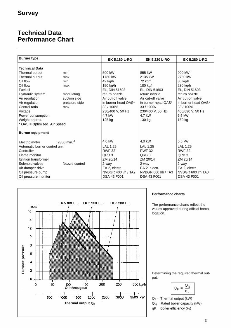
1 Solenoid valve (return oil) 2 Oil pressure pump 3 Suction oil connection4 Return oil 5 Filter 6 Solenoid valve (supply oil) 7 Oil flow controller (return oil)
8 Switch box with ignition transformer, switch and connec-ting terminals
9 Scale for nozzle rod adjustment 10 Connecting flange 11 Insulating base 12 Burner tube 13 Flame cup 14 Electric motor
15 Flame monitor 16 Inspection glass 17 Burner housing 18 Air suction box 19 Continuous compound control 20 Electric servomotor for com-
pound control 21 Swivel flange
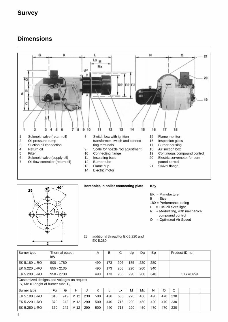
Boreholes in boiler connecting plate
25 additional thread for EK 5.220 and EK 5.280
Key
EK = Manufacturer 5 = Size 180 = Performance rating L = Fuel oil extra light R = Modulating, with mechanical
compound control O = Optimized Air Speed
Burner type Thermal outputkW
A B C dφ Dφ Eφ Product-ID-no.
EK 5.180 L-RO 500 - 1780 490 173 206 185 220 280
EK 5.220 L-RO 855 - 2135 490 173 206 220 260 340
EK 5.280 L-RO 950 - 2730 490 173 206 220 260 340 5 G 414/94
Customized designs and voltages on request Lx, Mx = Lenght of burner tube T2
Burner type Fφ G H J K L Lx M Mx N O Q
EK 5.180 L-RO 310 242 M 12 230 500 420 685 270 450 420 470 230
EK 5.220 L-RO 370 242 M 12 290 500 440 715 290 450 420 470 230
EK 5.280 L-RO 370 242 M 12 290 500 440 715 290 450 470 470 230
5
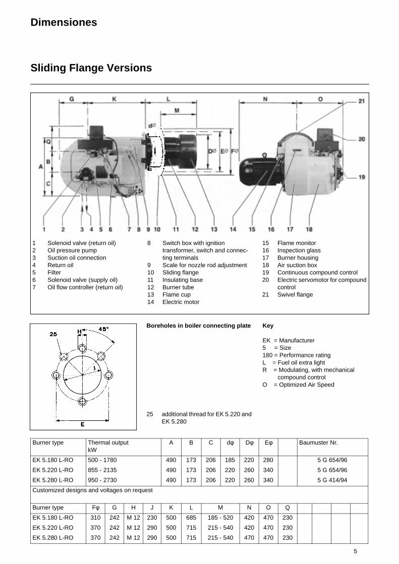
Dimensiones
Sliding Flange Versions
1 Solenoid valve (return oil) 2 Oil pressure pump 3 Suction oil connection4 Return oil 5 Filter 6 Solenoid valve (supply oil) 7 Oil flow controller (return oil)
8 Switch box with ignition transformer, switch and connec-ting terminals
9 Scale for nozzle rod adjustment 10 Sliding flange 11 Insulating base 12 Burner tube 13 Flame cup 14 Electric motor
15 Flame monitor 16 Inspection glass 17 Burner housing 18 Air suction box 19 Continuous compound control 20 Electric servomotor for compound
control 21 Swivel flange
Burner type Thermal outputkW
A B C dφ Dφ Eφ Baumuster Nr.
EK 5.180 L-RO 500 - 1780 490 173 206 185 220 280 5 G 654/96
EK 5.220 L-RO 855 - 2135 490 173 206 220 260 340 5 G 654/96
EK 5.280 L-RO 950 - 2730 490 173 206 220 260 340 5 G 414/94
Customized designs and voltages on request
Burner type Fφ G H J K L M N O Q
EK 5.180 L-RO 310 242 M 12 230 500 685 185 - 520 420 470 230
EK 5.220 L-RO 370 242 M 12 290 500 715 215 - 540 420 470 230
EK 5.280 L-RO 370 242 M 12 290 500 715 215 - 540 470 470 230
Boreholes in boiler connecting plate
25 additional thread for EK 5.220 and EK 5.280
Key
EK = Manufacturer 5 = Size 180 = Performance rating L = Fuel oil extra light R = Modulating, with mechanical
compound control O = Optimized Air Speed
6
Burner Functions
Functional DescriptionFunctional Diagram
Continuous burner control
On account of the continuous oil control system with return nozzle, part of the oil is fed back through the return nozzle and is thus not involved in the combu-stion process. The amount of return oil is continuously controlled by the flow controller. A continuously reversible electromotor moves the compound regulating segment (4) according to the required burner capacity.
This segment simultaneously controls the flow controller (5), the air dampers and - via the longitudinal nozzle rod adjustment - the air in the burner head. The position of the air dampers can be adapted to the quantity of oil arriving for combustion over their entire regulating range. This is achieved by power trans-mission from the drive to the air dam-pers via a ball-bearing ratchet which runs on an adjustable steel segment.
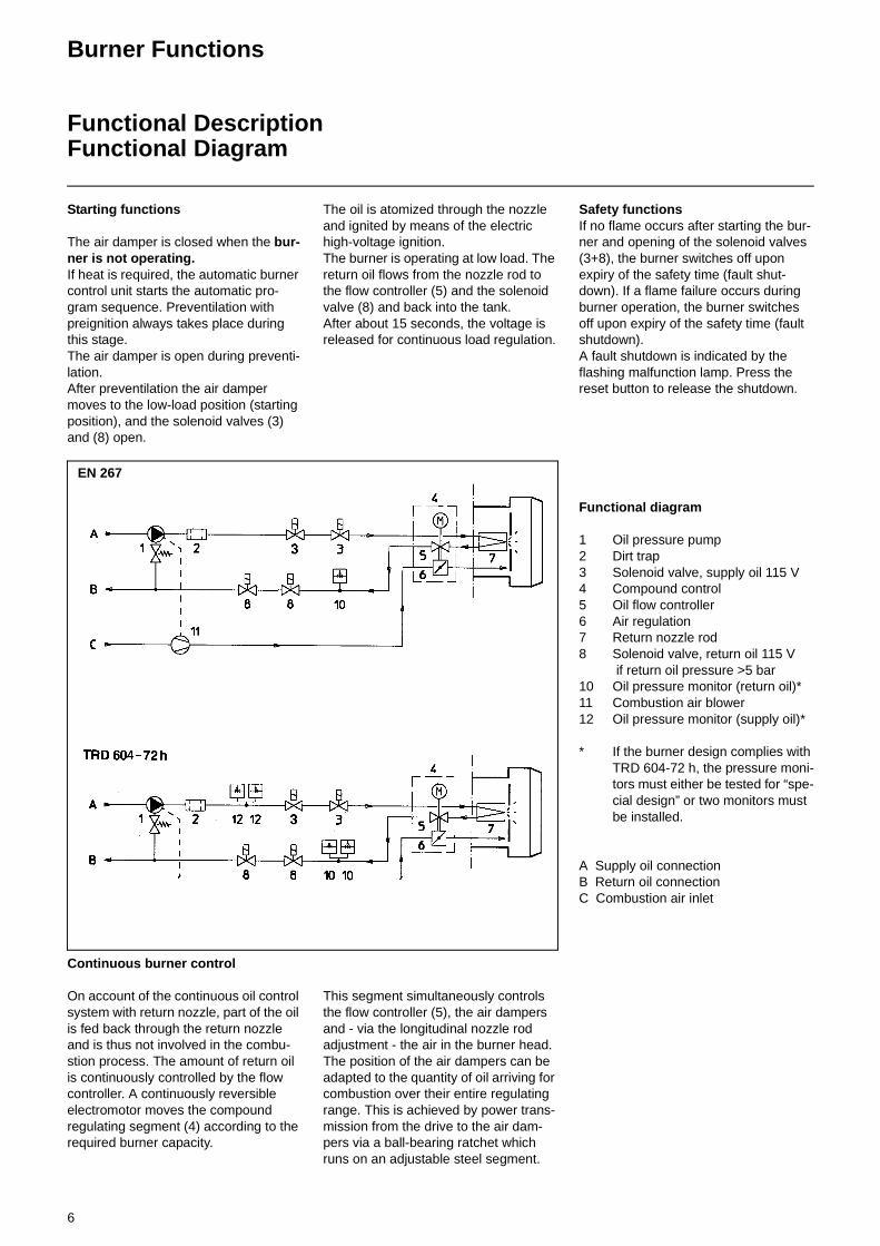
EN 267
Starting functions
The air damper is closed when the bur-ner is not operating. If heat is required, the automatic burner control unit starts the automatic pro-gram sequence. Preventilation with preignition always takes place during this stage. The air damper is open during preventi-lation. After preventilation the air damper moves to the low-load position (starting position), and the solenoid valves (3) and (8) open.
The oil is atomized through the nozzle and ignited by means of the electric high-voltage ignition. The burner is operating at low load. The return oil flows from the nozzle rod to the flow controller (5) and the solenoid valve (8) and back into the tank. After about 15 seconds, the voltage is released for continuous load regulation.
Safety functions If no flame occurs after starting the bur-ner and opening of the solenoid valves (3+8), the burner switches off upon expiry of the safety time (fault shut- down). If a flame failure occurs during burner operation, the burner switches off upon expiry of the safety time (fault shutdown). A fault shutdown is indicated by the flashing malfunction lamp. Press the reset button to release the shutdown.
Functional diagram
1 Oil pressure pump2 Dirt trap 3 Solenoid valve, supply oil 115 V4 Compound control5 Oil flow controller6 Air regulation 7 Return nozzle rod 8 Solenoid valve, return oil 115 V
if return oil pressure >5 bar 10 Oil pressure monitor (return oil)* 11 Combustion air blower 12 Oil pressure monitor (supply oil)*
* If the burner design complies with TRD 604-72 h, the pressure moni-tors must either be tested for “spe-cial design” or two monitors must be installed.
A Supply oil connection B Return oil connection C Combustion air inlet

7
Burner Functions
Functional Sequence of Burner Control Units LAL 1…RWF 40
The burner control units LAL 1... are designed for controlling and monitoring burners with multi-stage or modulating control systems. For a detailed functio-nal description of the burner control units, including technical data and plan-ning information, refer to
Technical DocumentationLAL 1 L&G 715 D
Functional diagram,modulating control
A = Start command A-B = Interval for flame formation B = Burner in operating position B-C =Burner operation
(heat Generation) C = Controlled shutdown
t1 Pre-venting timet2 Safety time t3 Preignition time, short t3” Preignition time, long t3n Post-ignition time t4 Interval between voltage on
terminals 18 and 19 t5 Interval between voltage on termi-
nals 19 and 20 t6 Post-venting time t7 Interval between Start command
and voltage on terminal 7 t11 Opening time of air damper t12 Closing time of air damper t13 Admissible after-burning time t16 Interval until OPEN command for
air damper
R Temperature or pressure controller Blower motor Z Ignition transformerBV fuel valve(s) LR Load controller LK Air damper RV Continuously adjustable fuel valve FS Flame signal
In steplessly variable burners use is made of the RWF 40 industrial control-ler. This has specifically been designed for use with furnace systems, preferably for temperature and pressure control-lers in conjunction with burners featu-ring steplessly variable fuel throughput rates. For adjusting the controller to the controlled condition, the desired set-point range and the way of detecting the actual value, the software configuration is structured accordingly. Technical Documentation
RWF 40 Landis & Staefa 7865
8
Installation
Mounting the Burner to the Heat GeneratorElektrical Connection
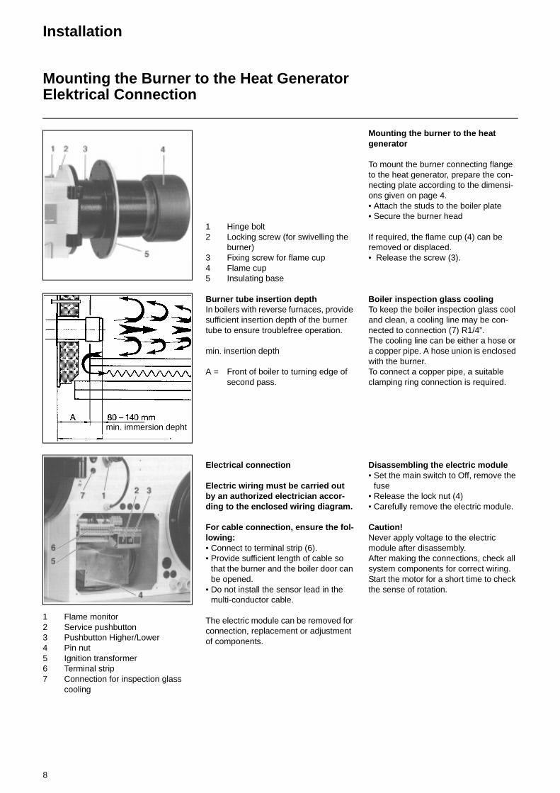
1 Hinge bolt 2 Locking screw (for swivelling the
burner)3 Fixing screw for flame cup 4 Flame cup 5 Insulating base
Burner tube insertion depth In boilers with reverse furnaces, provide sufficient insertion depth of the burner tube to ensure troublefree operation.
min. insertion depth
A = Front of boiler to turning edge of second pass.
Electrical connection
Electric wiring must be carried out by an authorized electrician accor-ding to the enclosed wiring diagram.
For cable connection, ensure the fol-lowing: • Connect to terminal strip (6). • Provide sufficient length of cable so
that the burner and the boiler door can be opened.
• Do not install the sensor lead in the multi-conductor cable.
The electric module can be removed for connection, replacement or adjustment of components.
Mounting the burner to the heat generator
To mount the burner connecting flange to the heat generator, prepare the con-necting plate according to the dimensi-ons given on page 4. • Attach the studs to the boiler plate • Secure the burner head
If required, the flame cup (4) can be removed or displaced. • Release the screw (3).
Boiler inspection glass cooling To keep the boiler inspection glass cool and clean, a cooling line may be con-nected to connection (7) R1/4”. The cooling line can be either a hose or a copper pipe. A hose union is enclosed with the burner. To connect a copper pipe, a suitable clamping ring connection is required.
Disassembling the electric module • Set the main switch to Off, remove the
fuse • Release the lock nut (4) • Carefully remove the electric module.
Caution! Never apply voltage to the electric module after disassembly. After making the connections, check all system components for correct wiring. Start the motor for a short time to check the sense of rotation.
min. immersion depht
1 Flame monitor 2 Service pushbutton3 Pushbutton Higher/Lower4 Pin nut 5 Ignition transformer6 Terminal strip 7 Connection for inspection glass
cooling
9
Installation
Oil ConnectionSupply Oil RegulationStart-Up
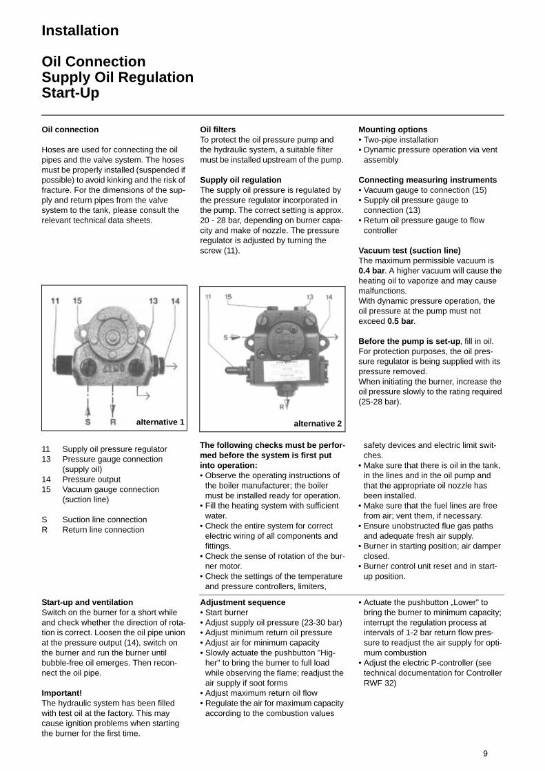
Oil connection
Hoses are used for connecting the oil pipes and the valve system. The hoses must be properly installed (suspended if possible) to avoid kinking and the risk of fracture. For the dimensions of the sup-ply and return pipes from the valve system to the tank, please consult the relevant technical data sheets.
11 Supply oil pressure regulator13 Pressure gauge connection
(supply oil) 14 Pressure output 15 Vacuum gauge connection
(suction line)
S Suction line connectionR Return line connection
Oil filters To protect the oil pressure pump and the hydraulic system, a suitable filter must be installed upstream of the pump.
Supply oil regulation The supply oil pressure is regulated by the pressure regulator incorporated in the pump. The correct setting is approx. 20 - 28 bar, depending on burner capa-city and make of nozzle. The pressure regulator is adjusted by turning the screw (11).
Mounting options • Two-pipe installation • Dynamic pressure operation via vent
assembly
Connecting measuring instruments• Vacuum gauge to connection (15) • Supply oil pressure gauge to
connection (13) • Return oil pressure gauge to flow
controller
Vacuum test (suction line) The maximum permissible vacuum is 0.4 bar. A higher vacuum will cause the heating oil to vaporize and may cause malfunctions. With dynamic pressure operation, the oil pressure at the pump must not exceed 0.5 bar.
Before the pump is set-up, fill in oil. For protection purposes, the oil pres-sure regulator is being supplied with its pressure removed. When initiating the burner, increase the oil pressure slowly to the rating required (25-28 bar).
alternative 1 alternative 2
The following checks must be perfor-med before the system is first put into operation:• Observe the operating instructions of
the boiler manufacturer; the boiler must be installed ready for operation.
• Fill the heating system with sufficient water.
• Check the entire system for correct electric wiring of all components and fittings.
• Check the sense of rotation of the bur-ner motor.
• Check the settings of the temperature and pressure controllers, limiters,
safety devices and electric limit swit-ches.
• Make sure that there is oil in the tank, in the lines and in the oil pump and that the appropriate oil nozzle has been installed.
• Make sure that the fuel lines are free from air; vent them, if necessary.
• Ensure unobstructed flue gas paths and adequate fresh air supply.
• Burner in starting position; air damper closed.
• Burner control unit reset and in start- up position.
Start-up and ventilation Switch on the burner for a short while and check whether the direction of rota-tion is correct. Loosen the oil pipe union at the pressure output (14), switch on the burner and run the burner until bubble-free oil emerges. Then recon-nect the oil pipe.
Important! The hydraulic system has been filled with test oil at the factory. This may cause ignition problems when starting the burner for the first time.
Adjustment sequence• Start burner • Adjust supply oil pressure (23-30 bar) • Adjust minimum return oil pressure• Adjust air for minimum capacity• Slowly actuate the pushbutton "Hig-
her" to bring the burner to full load while observing the flame; readjust the air supply if soot forms
• Adjust maximum return oil flow • Regulate the air for maximum capacity
according to the combustion values
• Actuate the pushbutton „Lower" to bring the burner to minimum capacity; interrupt the regulation process at intervals of 1-2 bar return flow pres-sure to readjust the air supply for opti-mum combustion
• Adjust the electric P-controller (see technical documentation for Controller RWF 32)
10
Start-Up
Burner Head SettingDimensiones
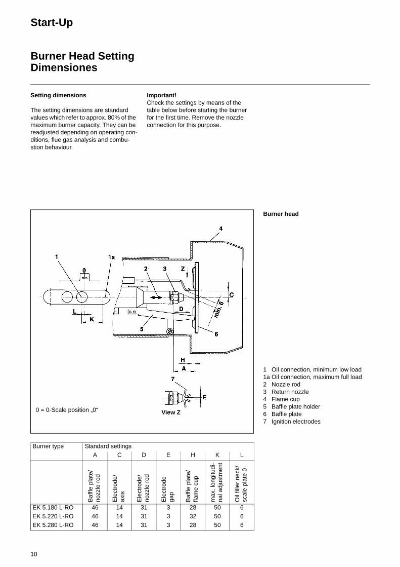
Setting dimensions
The setting dimensions are standard values which refer to approx. 80% of the maximum burner capacity. They can be readjusted depending on operating con-ditions, flue gas analysis and combu-stion behaviour.
Important! Check the settings by means of the table below before starting the burner for the first time. Remove the nozzle connection for this purpose.
Burner head
1 Oil connection, minimum low load1a Oil connection, maximum full load 2 Nozzle rod 3 Return nozzle4 Flame cup 5 Baffle plate holder6 Baffle plate 7 Ignition electrodes
0 = 0-Scale position „0“ View Z
Burner type Standard settingsA C D E H K L
Baf
fle p
late
/no
zzle
rod
Ele
ctro
de/
axis
Ele
ctro
de/
nozz
le r
od
Ele
ctro
dega
p
Baf
fle p
late
/fla
me
cup
max
. lon
gitu
di-
nal a
djus
tmen
t
Oil
fille
r ne
ck/
scal
e pl
ate
0
EK 5.180 L-RO 46 14 31 3 28 50 6
EK 5.220 L-RO 46 14 31 3 32 50 6EK 5.280 L-RO 46 14 31 3 28 50 6
11
Start-up
Return Nozzle Rod RDN
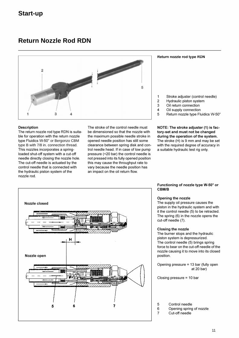
'HVFULSWLRQ7KH�UHWXUQ�QR]]OH�URG�W\SH�5'1�LV�VXLWD�EOH�IRU�RSHUDWLRQ�ZLWK�WKH�UHWXUQ�QR]]OH�W\SH�)OXLGLFV�:�����or Bergonzo CBM type B with 7/8 in. connection thread��7KLV�QR]]OHV�LQFRUSRUDWHV�D�VSULQJ�ORDGHG�VKXW�RII�V\VWHP�ZLWK�D�FXW�RII�QHHGOH�GLUHFWO\�FORVLQJ�WKH�QR]]OH�KROH��7KH�FXW�RII�QHHGOH�LV�DFWXDWHG�E\�WKH�FRQWURO�QHHGOH�WKDW�LV�FRQQHFWHG�ZLWK�WKH�K\GUDXOLF�SLVWRQ�V\VWHP�RI�WKH�QR]]OH�URG�
7KH�VWURNH�RI�WKH�FRQWURO�QHHGOH�PXVW�EH�GLPHQVLRQHG�VR�WKDW�WKH�QR]]OH�ZLWK�WKH�PD[LPXP�SRVVLEOH�QHHGOH�VWURNH�LQ�RSHQHG�QHHGOH�SRVLWLRQ�KDV�VWLOO�VRPH�FOHDUDQFH�EHWZHHQ�VSULQJ�GLVN�DQG�FRQ�WURO�QHHGOH�KHDG��,I�LQ�FDVH�RI�ORZ�SXPS�SUHVVXUH������EDU��WKH�FRQWURO�QHHGOH�LV�QRW�SUHVVHG�LQWR�LWV�IXOO\�RSHQHG�SRVLWLRQ�WKLV�PD\�FDXVH�WKH�WKURXJKSXW�UDWH�WR�YDU\�EHFDXVH�WKH�QHHGOH�SRVLWLRQ�KDV�DQ�LPSDFW�RQ�WKH�RLO�UHWXUQ�IORZ�
5HWXUQ�QR]]OH�URG�W\SH�5'1
� 6WURNH�DGMXVWHU��FRQWURO�QHHGOH�� +\GUDXOLF�SLVWRQ�V\VWHP� 2LO�UHWXUQ�FRQQHFWLRQ� 2LO�VXSSO\�FRQQHFWLRQ� 5HWXUQ�QR]]OH�W\SH�)OXLGLFV�:����
127(��7KH�VWURNH�DGMXVWHU�����LV�IDF�WRU\�VHW�DQG�PXVW�QRW�EH�FKDQJHG�GXULQJ�WKH�RSHUDWLRQ�RI�WKH�V\VWHP��7KH�VWURNH��+��LV���PP�DQG�PD\�EH�VHW�ZLWK�WKH�UHTXLUHG�GHJUHH�RI�DFFXUDF\�LQ�D�VXLWDEOH�K\GUDXOLF�WHVW�ULJ�RQO\��
)XQFWLRQLQJ�RI�QR]]OH�W\SH�:�����RU�&%0�%
2SHQLQJ�WKH�QR]]OH7KH�VXSSO\�RLO�SUHVVXUH�FDXVHV�WKH�SLVWRQ�LQ�WKH�K\GUDXOLF�V\VWHP�DQG�ZLWK�LW�WKH�FRQWURO�QHHGOH�����WR�EH�UHWUDFWHG�7KH�VSULQJ�����LQ�WKH�QR]]OH�RSHQV�WKH�FXW�RII�QHHGOH�����
&ORVLQJ�WKH�QR]]OH7KH�EXUQHU�VWRSV�DQG�WKH�K\GUDXOLF�SLVWRQ�V\VWHP�LV�GHSUHVVXUL]HG�7KH�FRQWURO�QHHGOH�����EULQJV�VSULQJ�IRUFH�WR�EHDU�RQ�WKH�FXW�RII�QHHGOH�RI�WKH�QR]]OH�FDXVLQJ�LW�WR�PRYH�LQWR�LWV�FORVHG�SRVLWLRQ�
2SHQLQJ�SUHVVXUH� ����EDU��IXOO\�RSHQDW����EDU�
&ORVLQJ�SUHVVXUH� ����EDU
� &RQWURO�QHHGOH� 2SHQLQJ�VSULQJ�RI�QR]]OH� &XW�RII�QHHGOH
1R]]OH�FORVHG
1R]]OH�RSHQ
12
Start-up
Nozzle Selection, Typ W-50°
Return nozzle
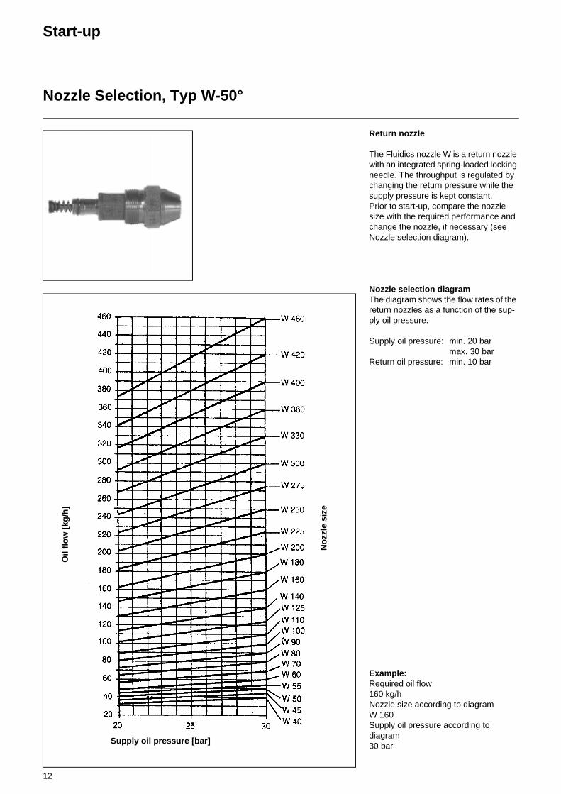
The Fluidics nozzle W is a return nozzle with an integrated spring-loaded locking needle. The throughput is regulated by changing the return pressure while the supply pressure is kept constant.Prior to start-up, compare the nozzle size with the required performance and change the nozzle, if necessary (see Nozzle selection diagram).
Nozzle selection diagram The diagram shows the flow rates of the return nozzles as a function of the sup-ply oil pressure.
Supply oil pressure: min. 20 bar max. 30 bar Return oil pressure: min. 10 bar
Example: Required oil flow160 kg/h Nozzle size according to diagram W 160 Supply oil pressure according to diagram30 bar
Supply oil pressure [bar]
Oil
flo
w [
kg/h
]
No
zzle
siz
e
13
Adjustments
Air Regulation
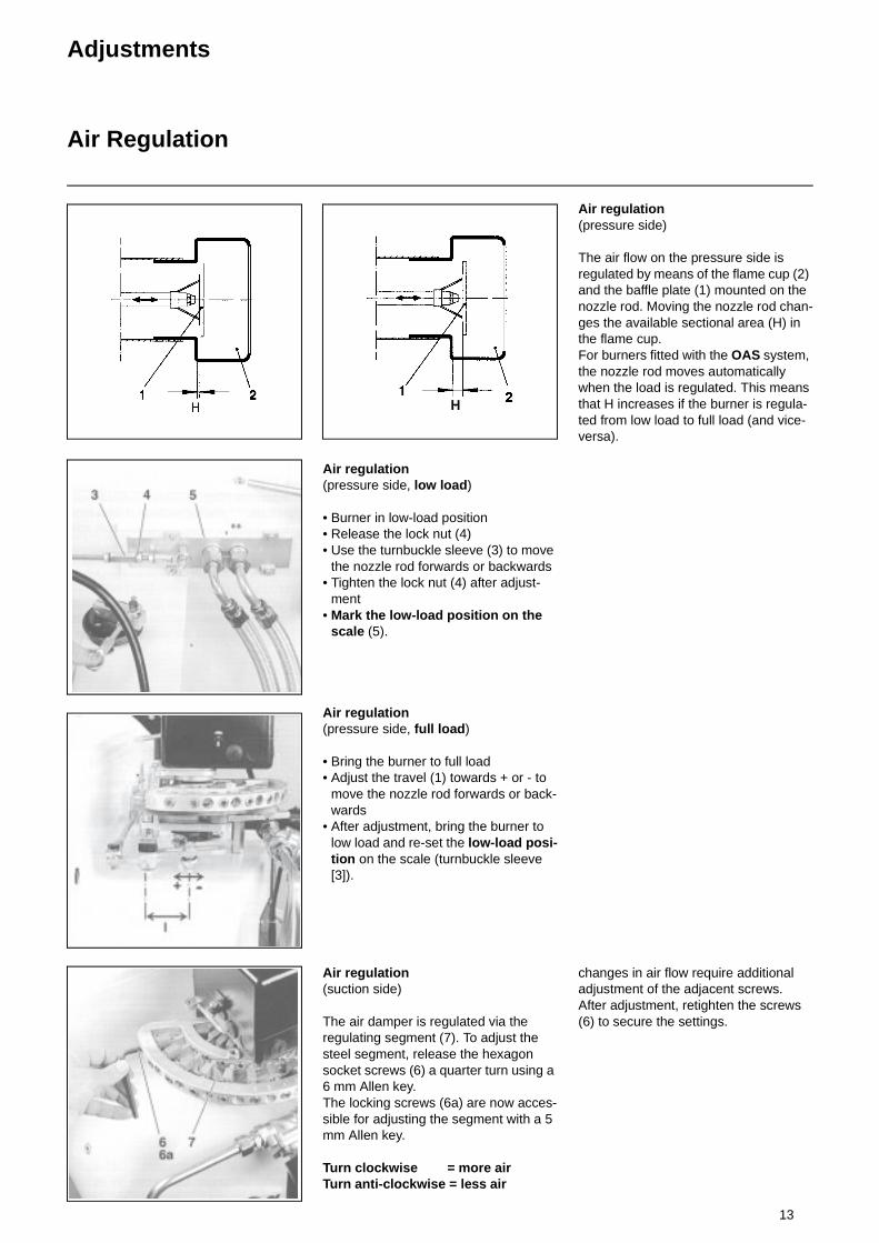
Air regulation (pressure side, low load)
• Burner in low-load position• Release the lock nut (4) • Use the turnbuckle sleeve (3) to move
the nozzle rod forwards or backwards • Tighten the lock nut (4) after adjust-
ment • Mark the low-load position on the
scale (5).
Air regulation (pressure side, full load)
• Bring the burner to full load • Adjust the travel (1) towards + or - to
move the nozzle rod forwards or back-wards
• After adjustment, bring the burner to low load and re-set the low-load posi-tion on the scale (turnbuckle sleeve [3]).
Air regulation (suction side)
The air damper is regulated via the regulating segment (7). To adjust the steel segment, release the hexagon socket screws (6) a quarter turn using a 6 mm Allen key. The locking screws (6a) are now acces-sible for adjusting the segment with a 5 mm Allen key.
Turn clockwise = more air Turn anti-clockwise = less air
Air regulation(pressure side)
The air flow on the pressure side is regulated by means of the flame cup (2) and the baffle plate (1) mounted on the nozzle rod. Moving the nozzle rod chan-ges the available sectional area (H) in the flame cup. For burners fitted with the OAS system, the nozzle rod moves automatically when the load is regulated. This means that H increases if the burner is regula-ted from low load to full load (and vice-versa).
changes in air flow require additional adjustment of the adjacent screws. After adjustment, retighten the screws (6) to secure the settings.
14
Adjustments
Return Oil RegulationOil Pressure Monitor
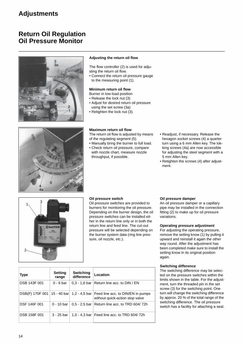
Adjusting the return oil flow
The flow controller (2) is used for adju-sting the return oil flow. • Connect the return oil pressure gauge
to the measuring point (1).
Minimum return oil flow Burner in low-load position• Release the lock nut (3) • Adjust for desired return oil pressure
using the set screw (3a) • Retighten the lock nut (3).
Maximum return oil flow The return oil flow is adjusted by means of the regulating segment (5). • Manually bring the burner to full load.• Check return oil pressure, compare
with nozzle chart, measure nozzle throughput, if possible.
• Readjust, if necessary. Release the hexagon socket screws (4) a quarter turn using a 6 mm Allen key. The lok-king screws (4a) are now accessible for adjusting the steel segment with a 5 mm Allen key.
• Retighten the screws (4) after adjust-ment.
Oil pressure switch Oil pressure switches are provided to burners for monitoring the oil pressure. Depending on the burner design, the oil pressure switches can be installed eit-her in the return line only or in both the return line and feed line. The cut-out pressure will be selected depending on the burner system data (ring line pres-sure, oil nozzle, etc.).
Oil pressure damperAn oil pressure damper or a capillary pipe may be installed in the connection fitting (2) to make up for oil pressure variations.
Operating pressure adjustmentFor adjusting the operating pressure, remove the setting know (1) by pulling it upward and reinstall it again the other way round. After the adjustment has been completed make sure to install the setting know in its original position again.
Switching differenceThe switching difference may be selec-ted on the pressure switches within the limits shown in the table. For the adjust-ment, turn the threaded pin in the set screw (3) for the switching point. One turn will change the switching difference by approx. 20 % of the total range of the switching difference. The oil pressure switch has a facility for attaching a seal.
1
2
3
Type Setting range
Switching difference Location
DSB 143F 001 0 - 6 bar 0,3 - 1,6 bar Return line acc. to DIN / EN
DSB(F) 170F 001 15 - 40 bar 1,2 - 4,5 bar Feed line acc. to DIN/EN in pumps without quick-action stop valve
DSF 146F 001 0 - 10 bar 0,5 - 2,5 bar Return line acc. to TRD 604/ 72h
DSB 158F 001 3 - 25 bar 1,0 - 4,3 bar Feed line acc. to TRD 604/ 72h
15
Adjustments
Adjusting the Limit Switches at the Electric Servomotor
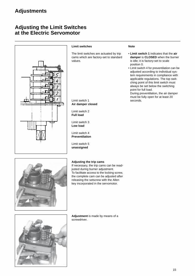
Limit switches
The limit switches are actuated by trip cams which are factory-set to standard values.
Limit switch 1 Air damper closed
Limit switch 2 Full load
Limit switch 3 Low load
Limit switch 4 Preventilation
Limit switch 5unassigned
Adjusting the trip cams If necessary, the trip cams can be read-justed during burner adjustment. To facilitate access to the locking screw, the complete cam can be adjusted after releasing the setscrew with the Allen key incorporated in the servomotor.
Adjustment is made by means of a screwdriver.
Note
• Limit switch 1 indicates that the air damper is CLOSED when the burner is idle; it is factory-set to scale position 0.
• Limit switch 4 for preventilation can be adjusted according to individual sys- tem requirements in compliance with applicable regulations. The top swit-ching point of this limit switch must always be set below the switching point for full load. During preventilation, the air damper must be fully open for at least 20 seconds.
16
Service-Instructions
MaintenanceTroubleshooting
Burner malfunction, general
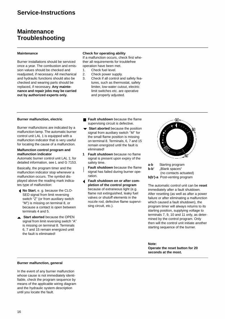
In the event of any burner malfunction whose cause is not immediately identi-fiable, check the program sequence by means of the applicable wiring diagram and the hydraulic system description until you locate the fault.
a-b Starting programb-b’ „Blank spaces“
(no contacts actuated) b(b’)-a Post-venting program
The automatic control unit can be reset immediately after a fault shutdown. After resetting (as well as after a power failure or after eliminating a malfunction which caused a fault shutdown), the program timer will always returns to its starting position, supplying voltage to terminals 7, 9, 10 and 11 only, as deter-mined by the control program. Only then will the control unit initiate another starting sequence of the burner.
Note: Operate the reset button for 20 seconds at the most.
Burner malfunction, electric
Burner malfunctions are indicated by a malfunction lamp. The automatic burner control unit LAL 1 is equipped with a malfunction indicator that is very useful for locating the cause of a malfunction.
Malfunction control program and malfunction indicator Automatic burner control unit LAL 1; for detailed information, see L and G 7153.
Basically, the program timer and the malfunction indicator stop whenever a malfunction occurs. The symbol dis-played above the reading mark indica-tes type of malfunction:
No Start, e. g. because the CLO-SED signal from limit reversing switch “Z” (or from auxiliary switch "M”) is missing on terminal 8, or because a contact is open between terminals 4 and 5.
Start aborted because the OPEN signal from limit reversing switch “A” is missing on terminal 8. Terminals 6, 7 and 15 remain energized until the fault is eliminated!
Fault shutdown because the flame supervising circuit is defective.
Start aborted because the position signal from auxiliary switch ’’M’’ for the small flame position is missing on terminal 8. Terminals, 6, 7 and 15 remain energized until the fault is eliminated!
1 Fault shutdown because no flame signal is present upon expiry of the safety time. Fault shutdown because the flame signal has failed during burner ope-ration. Fault shutdown on or after com-pletion of the control program because of extraneous light (e.g. flame not extinguished, leaky fuel valves or shutoff elements in the nozzle rod, defective flame supervi-sing circuit, etc.).
Maintenance
Burner installations should be serviced once a year. The combustion and emis-sion values should be checked and readjusted, if necessary. All mechanical and hydraulic functions should also be checked and wearing parts should be replaced, if necessary. Any mainte-nance and repair jobs may be carried out by authorized experts only.
Check for operating ability If a malfunction occurs, check first whe-ther all requirements for troublefree operation have been met.1. Check fuel level. 2. Check power supply. 3. Check if all control and safety fea-
tures, such as thermostat, safety limiter, low-water cutout, electric limit switches etc. are operative and properly adjusted.
��
&XVWRPHU�VHUYLFH�
ELCO Klöckner Heiztechnik GmbHStruppener Str.D - 01796 PirnaPhone: 03501 / 795-30


