32
D860MGB rev02.docx OPERATING INSTRUCTIONS for HI PUMP UNIT

D860MGB rev02.docx
OPERATING INSTRUCTIONS
for
HI PUMP UNIT
D860MGB rev02.docx
Sommario 1 GENERAL INFORMATION BEFORE INSTALLING ................................................................................. 4
1.1 INTRODUCTION ............................................................................................................................... 4 1.2 LIABILITY AND GUARANTEE .......................................................................................................... 4 1.3 SAFETY MEASURES ........................................................................................................................ 4 1.4 WARNING ON HOW TO OPERATE ................................................................................................. 4
SAFETY ON THE WORKING PLACE ....................................................................................... 4 1.4.1
CLEANING ................................................................................................................................. 5 1.4.2
INSTALLATION ......................................................................................................................... 5 1.4.3
MAINTENANCE ......................................................................................................................... 5 1.4.4
ANTI-POLLUTION MEASURES ................................................................................................ 5 1.4.5
1.5 CONTROL OF THE SUPPLIED MATERIAL ..................................................................................... 5 1.6 IDENTIFICATION PLATES ............................................................................................................... 5 1.7 FEATURES OF THE MACHINE ROOM ........................................................................................... 6
2 TRANSPORT AND STORAGE ................................................................................................................. 6
2.1 GENERAL INFORMATION ............................................................................................................... 6 2.2 PUMP UNITS ..................................................................................................................................... 6 2.3 INVERTER ......................................................................................................................................... 7 2.4 FLEXIBLE HOSES AND RIGID PIPES ............................................................................................. 7
3 ASSEMBLING OF THE HYDRAULIC COMPONENTS ............................................................................ 7
3.1 PUMP UNIT ....................................................................................................................................... 7 3.2 PIPE AND HYDRAULIC CONNECTIONS ........................................................................................ 7
4 ELECTRICAL CONNECTIONS ................................................................................................................. 9
4.1 GENERAL REGULATIONS ............................................................................................................... 9 4.2 CONNECTION BOX .......................................................................................................................... 9 4.3 ELECTRICAL CONNECTION OF THE THREE-PHASE MOTOR .................................................. 10 4.4 MOTOR PROTECTION WITH THERMISTORS ............................................................................. 11 4.5 ELECTRICAL CONNECTION OF THE VALVE GROUP ................................................................ 11 4.6 POSITIONING OF THE SHAFT SWITCHES FOR THE DECELERATION DISTANCE ................. 12 4.7 ELECTRICAL GROUP INVERTER ................................................................................................. 12
INTRODUCTION ..................................................................................................................... 12 4.7.1
WARNING ................................................................................................................................ 12 4.7.2
5 OIL FOR LIFTS - CIRCUIT FILLING AND AIR PURGING ..................................................................... 13
5.1 CHARACTERISTICS ....................................................................................................................... 13 5.2 CHOICE OF THE OIL ...................................................................................................................... 13 5.3 CIRCUIT FILLING AND AIR PURGING .......................................................................................... 14
6 CONTROLS AND TEST .......................................................................................................................... 16
6.1 CHECK OF THE OIL LEVEL IN THE TANK ................................................................................... 16 6.2 CHECK OF THE MAX. PRESSURE ............................................................................................... 16 6.3 CHECK OF THE START IN UPWARD DIRECTION....................................................................... 16 6.4 CHECK OF THE SEALING OF SEALS AND PIPES ...................................................................... 16 6.5 CHECK OF THE RUPTURE VALVE INTERVENTION ................................................................... 17 6.6 CHECK OF THE INSTALLATION AT TWICE THE STATIC PRESSURE ...................................... 17 6.7 CHECK OF THE ROD COUNTER-PRESSURE AND HAND WORKING ...................................... 17 6.8 CHECK AND ADJUSTING OF THE HAND PUMP ......................................................................... 17 6.9 NOISE .............................................................................................................................................. 17 6.10 MANOMETER SHUT-OFF .............................................................................................................. 18
7 ADJUSTING AND TEST OF THE OMARLIFT RUPTURE VALVE ......................................................... 18
7.1 GENERAL INFORMATION ............................................................................................................. 18

D860MGB rev02.docx
7.2 TEST AND WORKING OF THE RUPTURE VALVE ....................................................................... 18
8 VALVE GROUP AND INVERTER’S PARAMETER CALIBRATION AND ADJUSTMENT ..................... 18
8.1 GENERAL INFORMATION ............................................................................................................. 18 8.2 HYDRAULIC SCHEME .................................................................................................................... 19 8.3 ADJUSTING AND REGULATION OF “HI” VALVE GROUP ........................................................... 20
OVER-PRESSURE VALVE CALIBRATION: SCREW N°1 ..................................................... 20 8.3.1
ROD COUNTER-PRESSURE AND ROPE ANTI-LOOSENING CALIBRATION: SCREW N. 38.3.2
20 CALIBRATION OF THE HAND PUMP PRESSURE: SCREW N. 9 ........................................ 21 8.3.3
CALIBRATION OF THE PRESSURE SWITCHES (PRESSURE MIN. - MAX. - OVERLOAD)8.3.4
22 8.4 INVERTER SETTING AND PROGRAMMING ................................................................................ 23
9 OPTIONAL ACCESSORIES ................................................................................................................... 23
9.1 OIL HEATING RESISTANCE (optional) .......................................................................................... 23 9.2 OIL COOLING (optional) ................................................................................................................. 23
GENERAL INFORMATION ..................................................................................................... 23 9.2.1
COOLING SYSTEM WITH AIR ............................................................................................... 24 9.2.2
COOLING SYSTEM WITH WATER ........................................................................................ 24 9.2.3
10 MAINTENANCE ................................................................................................................................... 25
10.1 GENERAL INFORMATION ............................................................................................................. 25 10.2 OIL LOSSES AND CAR LOWERING .............................................................................................. 25
LOSSES ALONG THE PIPES ................................................................................................. 25 10.2.1
CYLINDER LOSSES ............................................................................................................... 25 10.2.2
LOSSES INSIDE THE VALVE GROUP .................................................................................. 25 10.2.3
10.3 AIR PRESENCE IN THE OIL .......................................................................................................... 29 10.4 FILTER CLEANING INSIDE VALVE GROUP ................................................................................. 29 10.5 MINERAL OIL DETERIORATION ................................................................................................... 29 10.6 ELECTRICAL ANTI-CREEP SYSTEM (RE-LEVELING) ................................................................ 30 10.7 EMERGENCY LOWERING WITH THE BATTERY ......................................................................... 30 10.8 PLATES, DIAGRAMS, INSTRUCTIONS ......................................................................................... 30 10.9 INVERTER MAINTENACE .............................................................................................................. 30
MEGGER TEST ....................................................................................................................... 30 10.9.1
10.10 RECOMMENDED PERIODIC MAINTENANCE .............................................................................. 30
11 DIMENSIONS AND WEIGHTS............................................................................................................ 31
11.1 DIMENSIONS AND WEIGHTS OF THE PUMP UNITS .................................................................. 31 11.2 DIMENSIONS AND WEIGHTS OF INVERTER AND RESISTORS ................................................ 31

D860MGB rev02.docx 4/32
1 GENERAL INFORMATION BEFORE INSTALLING
1.1 INTRODUCTION
The assembly, installation, put into action and maintenance of the hydraulic lift have to be carried out only by
trained staff. Before starting with any kind of work on the hydraulic components, it is necessary that the
trained staff reads these operating instructions carefully; in particular chapters 1.3 “SAFETY MEASURES”
and 1.4 “WARNING ON HOW TO OPERATE”. These "Operating instructions" are an integral part of the
installation and have to be kept in a safe and accessible place.
1.2 LIABILITY AND GUARANTEE
These operating instructions are addressed to staff competent in installing, adjusting and maintenance
operations on the hydraulic lifts.
OmarLift does not take responsibility for any kind of damage caused by use different from the one hereby
explained, lack of experience, carelessness by people assigned to the assembling, repair operations of the
hydraulic components.
OmarLift guarantee is not valid anymore if components or spare parts different from the original ones are
installed, and if modifications or repair operations are carried out by non-authorized or non-qualified workers.
1.3 SAFETY MEASURES
Installers and maintenance staff are fully responsible for their safety while working. All the safety
measures in force have to be observed carefully to prevent competent staff or any possible non-
competent persons or objects, from damages or accidents. These operating instructions report
some symbols, which correspond to important safety measures:
Danger: This symbol draws attention to high risk of injury of persons.
It must always be obeyed.
Warning: This symbol draws attention to information which, if it is not observed, can lead to injury to
persons or extensive damage to property.
It must always be observed.
Caution: This symbol draws attention to information containing important instructions for use.
Failure to observe the instructions can lead to damage or danger.
1.4 WARNING ON HOW TO OPERATE
Hereby follow the most important principles which always have to be observed while working on hydraulic
installations. These principles will not be repeated in the following chapters, because they are considered to
be known.
SAFETY ON THE WORKING PLACE 1.4.1
Lack of observing simple safety rules or lack of attention can lead to even severe incidents. In case
of works on the hydraulic installation, it is necessary to:
Get the lift to be at the bottom directly on the buffer;
Block the main switch to be sure that the lift cannot be put into service unintentionally;
Get the oil pressure to zero before opening any part of the hydraulic circuit, caps or unscrewing
fittings.
Prevent cinders from getting in contact with oil, rod and its seal and all the elastic parts of the
installation during welding operations;
Get rid of the spilled oil, oil leakage, keep the installation always clean so that any leakage can be
easily detected.

D860MGB rev02.docx 5/32
CLEANING 1.4.2
Cinders and dirt inside the hydraulic installation cause bad working and precocious wear. Before assembling, it is necessary to clean the different parts with a lot of care:
- All the possible protection caps, plastic bags and tape used for packing have to be removed.
- The connection pipes, whether they are flexible or iron have to be cleaned perfectly from the inside.
Especially the iron pipes have to be cleaned from the inside and cinders have to be removed from
the ends. A pipe bender, not flame, has to be used to bend the iron pipe.
- Before pouring the oil into the pump unit tank, check that no dirt or water is inside it.
- Use always a good filter to pour or add oil in the tank.
- For the cleaning of the pipes and the pump unit do not use fraying clothes or steel wool.
- The cylinder head and all the plastic or rubber parts have to be protected if paint, concrete or
welding machines are used in their neighborhood.
- All the parts of the installation which have been disassembled to be tested or repaired, the sealing
surfaces, the pipes and the fittings have to be cleaned perfectly before being reassembled.
INSTALLATION 1.4.3
For the installation or the replacement of the hydraulic installation components, the following points have to
be observed:
- Only use the material advised by OmarLift (especially the hydraulic oil) and the original OmarLift
spare parts.
- Avoid the use of sealing materials such as silicone, plaster or hemp which could penetrate the
hydraulic circuit.
- In case of pipes bought directly from the market are being used, only choose the ones responding to
the safety measures in force and according to the pressure of the installation. Note that the only use
of the hard pipe to connect the pump unit to the cylinder can transmit and increase the noise.
- Install the flexible hoses with the right bending radius suggested by the manufacturers and avoid the
use of hoses which are longer than necessary.
MAINTENANCE 1.4.4
During the periodical works of maintenance besides normal tests, it should be remembered that:
- The damaged pipes have to be replaced immediately.
- Get rid of oil leakage and its causes.
- The possible spilled oil has to be collected, so that leakage can be easily detected.
- It’s necessary be sure that there are no unusual and excessive noises in the pump, the motor or the
suspensions. Eventually, get rid of them.
ANTI-POLLUTION MEASURES 1.4.5
Possible spilled oil from the circuit during repair operations has not to be spread in the environment, but has
to be promptly collected with cloths or sponges and disposed carefully in proper containers. In case of oil
replacement, also the waste oil has to be disposed in proper containers.
For the disposal of oil and clothes containing oil contact the specialized companies according to the
regulations in force in the country of operation. Concerning the rules against the water pollution (see
underground direct acting installations with high quantities of oil) act according to the national rules.
1.5 CONTROL OF THE SUPPLIED MATERIAL
When the material is withdrawn before signing the delivery document of the forwarding agent, check that the
goods correspond to the list reported in the delivery document and to the requested order.
1.6 IDENTIFICATION PLATES
The main supplied components have their own plate containing all the data needed to identify them:
- Cylinder: adhesive plate on the cylinder head.

D860MGB rev02.docx 6/32
- Rupture valve: plate fixed on the valve side.
- Pump unit: plate fixed on the tank cover.
- Flexible hose: test date, test pressure and manufacturer name engraved on the fitting.
1.7 FEATURES OF THE MACHINE ROOM
Before installing:
- Make sure that the shaft, pit, head and machine room correspond to the project data and respond to
the regulations in force, and:
- Make sure that access ways allow the passage of the different components to be installed.
- Make sure that the bottom of the pit is clean, dry and waterproof.
- Make sure that the shaft is ventilated and illuminated sufficiently.
- Make sure that the machine room has the access door with opening towards the outside, if possible
noise-proof, well-ventilated and its temperature preferably between 10 and 30 °C.
2 TRANSPORT AND STORAGE
2.1 GENERAL INFORMATION
For the transport and the storage of the hydraulic components, the general safety regulations always have to
be followed:
When loads have to be lifted, only use proper hoists and respect their max. capacity.
Never walk or stop under the hanging loads.
Avoid hydraulic components from shocks.
- If the hydraulic components have to be stored, first control that packaging and protections are in a
perfect state; if necessary repair or replace them with other more suitable ones.
- Store the hydraulic components in a dry place, dust free with a temperature between 5 and 30°C.
- If the cylinders or the pump units have to be stored for a long time, it is better for the preservation to
fill them with oil to prevent oxidation phenomena.
2.2 PUMP UNITS
The pump unit is protected by a thermo-shrinking plastic cover and plastic film. In case customers ask, the
pump unit can be packed in resistant cardboard or in a wooden cage.
TRANSPORT OF PUMP UNITS
Load and unload the pump units using clamp trucks. If the pump unit has to be lifted with ropes,
make them pass under the handles (see Figure 1).
The pump units cannot be placed on each other, if not packed in special wooden cages designed to.
Figure 1- Pump unit lifting with ropes

D860MGB rev02.docx 7/32
STORAGE OF THE PUMP UNITS
Store the pump units in a dry place with a temperature between 5 and 30°C.
Control the protection packaging and replace it if necessary..
If the pump units have to be stored for a long time, it is better to fill the tank with oil, at least until to
cover the electric motor.
2.3 INVERTER The inverter is delivered in a special packing or in a cardboard box.
STORAGE OF THE INVERTER
Store the inverter in a dry place at a temperature between 5° and 30°C.
Check the protective packaging and eventually replace it.
2.4 FLEXIBLE HOSES AND RIGID PIPES
PIPES TRANSPORT
Avoid harsh bending of the flexible hoses.
Prevent the flexible hoses from contact with caustic essences, solvents or other chemical
substances.
Transport the flexible hoses in their original packaging.
Avoid any kind of bending of the rigid pipes.
Transport the rigid pipes with their caps on the ends.
STORAGE OF THE PIPES
Store the pipes in a dry place, with a temperature between 5 and 30°C.
Prevent the flexible hoses from the direct sunlight or the near presence of a heat source.
Do not keep the flexible hoses stored for more than 2 years from the test date engraved on the fitting.
3 ASSEMBLING OF THE HYDRAULIC COMPONENTS
3.1 PUMP UNIT The serial number of the pump unit is reported on the plate on the tank cover.
- All the pump units and the shut-off valves are tested and adjusted before the delivery.
For this reason they can work immediately, without any further adjusting.
When the installation has been finished, the oil filled and the air purged, it will be possible to readjust the low
speed and the deceleration to optimize the installation working (see instructions in paragraph 8.4)
The pump unit room has to be located as close as possible to the lift shaft, has to be big enough,
with an almost constant temperature, possibly heated in winter and ventilated in summer. If
distances are bigger than 8-10 meters, please consider the pressure loss along the main pipe.
Avoid noise transmission by using anti-vibration pads under the tank and a flexible hose for the
connection of the pump unit to the cylinder.
- The tank is equipped with handholds to be displaced manually and to be lifted with an hoist (see
Figure 1).
3.2 PIPE AND HYDRAULIC CONNECTIONS Use cold drawn steel tubes, normalized and bonderized, special for hydraulic circuits, flexible hoses which
are tested and certified for high pressure or mixed connections to connect the pump unit to the cylinder.
- The shut-off valve can be turned to be better aligned with the pipe direction.
The shut-off valve can be turned to be better aligned with the pipe direction.
The main oil pipe as to be as short as possible and avoid narrow bending. The use of elbow fitting

D860MGB rev02.docx 8/32
has to be as reduced as possible.
When a rigid pipe is used, please note that:
The pipe cut has to be perfectly at 90°.
Figure 2 - "WALFORM" fitting
Possible bends have to be made when cold, using a proper pipe bending.
The use of a flame can cause cinders inside the pipe.
Cinders and dirt caused by the cut have to be completely eliminated
When connecting two pipes to a cutting ring, make sure that the two pipes are perfectly aligned and
that the cutting part of the ring is turned towards the end of the pipe. Before tightening the nut of the
fitting, oil both the thread and the ring. Therefore screw with power and unscrew to control that the
cutting ring has engraved. Finally, screw again definitely the nut of the fitting, tightening it well.
Non-normalized pipes are too hard and they can get out of the fitting!
Warning: some countries do not allow the use of a joint with a cutting ring. In these cases, it is
necessary to use a type of fitting called "WALFORM" for the connection (see Figure 2) or fittings to
be welded.
When a flexible hose is used, please note that:
The flexible hose has not to be subject to tension, torsion and the bends have to be as wide as
possible
The minimum bending radius given by the manufactures has to be respected. It is reported in the
following table:
TYPE OF FLEXIBLE PIPE
MINIMUN RADIUS
3/4” DN 20 240 mm
1 1/4” DN 32 420 mm
1 1/2” DN 40 500 mm
2” DN 50 660 mm
The pump units with a capacity from 360 to 600 l/min have a 2" outlet. These pump units can feed a single
cylinder with a rupture valve 2" or two cylinders together.
- In case of a single cylinder, the connection between the pump unit and the rupture valve can be made:
With a single flexible hose 2" and nipples 2", 60° angle (see Figure 3);
with two parallel steel pipes, diameter 42 mm and two three-way fittings 1 ½”x 2” x 1 ½” (see Figure
4)

D860MGB rev02.docx 9/32
Figure 3 - Connection with flex hose 2”
Figure 4 - Connection with two rigid pipes Ø 42
4 ELECTRICAL CONNECTIONS
4.1 GENERAL REGULATIONS Any electrical connection has to be carried out by trained and qualified staff, according to the specific
regulations.
Before starting any kind of work, always disconnect the electrical power opening the general switch.
The cables for the electrical power feeding have to have a section sufficient for the requested power.
Their isolation has to be suitable according to the voltage of the electrical network. The connection
cables have not to be put in contact with parts subject to strong heating.
The grounding cable has to be always connected to the bolt marked with the proper symbol.
4.2 CONNECTION BOX The connection box is on the pump unit cover, near the valve block..
The box of the standard pump unit includes (see Figure 5): a) Terminal block of the electrical motor
b) Grounding bolt
c) Thermostat for oil temperature 70°C
d) Motor thermistors 110°C
The pump unit box, cabled (optional), includes (see Figure 6):
a) Therminal block of the electrical motor
b) Grounding bolt
c) Terminals of the thermostat for the oil cooling (optional.)
d) Terminals of the max pressure switch (optional.)
e) Terminals of the min pressure switch (optional.)
f) Terminals coil EVD
g) Terminals coil EVE
h) Terminals of motor thermistors 110°C
i) Terminals of the oil thermostat 70°C
j) Terminals of the overload pressure switch (optional.)
2”
2”
2 x (1½” - Ø42)
2 x (1”½ - Ø42)

D860MGB rev02.docx 10/32
Figure 5 - Connection box for standard pump unit
4.3 ELECTRICAL CONNECTION OF THE THREE-PHASE MOTOR The terminals of the motor are already fixed to the terminal block inside the connection box.
In case of a direct start of the motor, frequency and one tension of the motor have to correspond to
the frequency and tension of the electrical power network.
The connection bands on the terminal block have to respect the diagram appearing on the motor
plate or the directions of the table (see Figure 7).
Figure 6 - Connection box for wired pump unit
DISPOSITION OF TERMINAL CONNECTION BANDS FOR THREE-PHASE MOTORS
DIRECT START

D860MGB rev02.docx 11/32
Line 230V -Motor 230/400
Line 400V -Motor 400/690
Line 415V -Motor 415/720
Line 400V -Motor 230/400
Line 690V -Motor 400/690
Line 720V -Motor 415/720
Figure 7 - Electrical connection of three-phase motors
4.4 MOTOR PROTECTION WITH THERMISTORS The motors, which work covered with oil, are supplied with their thermistors 110°C. The thermistors are
inserted in windings, one for each phase and they are connected in series.
Their resistance remains very low, under 110°C, but increases drastically when 110°C are reached in one or
in all windings.
For the motor protection, the thermistors have to be connected to a proper release electronic relay
susceptible to the resistance variation.
Warning: The thermistors have not to be submitted to tensions higher than 2,5 V.
When the thermistors are properly connected, they protect the motor against the overheating of the windings.
Overheating could be caused by:
- lack of a phase in the feeding
- too frequent activation
- excessive tension variations
- excessive oil temperature
4.5 ELECTRICAL CONNECTION OF THE VALVE GROUP The HI valve (see Figure 8) entails the following electro-valves:
The EVD ELECTRO-VALVE controls normal downward travel.
This electro-valve should be powered only during downward travel throughout the entire run.
EVE ELECTRO-VALVEV this electro-valve is used for emergency downward travel.
By powering the coil, the hydraulic valve will allow the slow speed downward travel of the car.
Figure 8 – Position of coils on the HI valve

D860MGB rev02.docx 12/32
4.6 POSITIONING OF THE SHAFT SWITCHES FOR THE DECELERATION
DISTANCE
Legenda:
F - Stop switch before landing (20-30 mm) (the soft stop travel is controlled by the inverter)
S – Upward travel deceleration distance (shaft switch)
D – Downward travel deceleration distance (shaft switch)
To achieve a good deceleration the contact at the entrance 9 of the inverter high speed, must be opened at a
distance from the arrival floor, that depends on the speed: the greater the distance, the higher the speed of
the unit.
The opening distance of the entrance high speed from landing be inferred by the following table:
Car
Speed
EVD de-energizing
Upward distance Downward distance
0,40 m/s 0,50 m 0,60 m
0,60 m/s 0,70 m 0,80 m
0,80 m/s 0,90 m 1 m
4.7 ELECTRICAL GROUP INVERTER
INTRODUCTION 4.7.1
OmarLift uses an inverter which operates in open loop condition, with a special software for hydraulic lifts. It
controls both the upward run and the downward run.
You can achieve the following benefits:
No starting current peaks. The maximum starting current never exceeds the nominal current.
Power Factor correction. Cosφ ≥ 0,97.
Energy saving.
Run comfort optimization.
Adjustable inspection speed
You can set a maximum limit (optional) for the absorbed power from the mains, in order to reduce
the installed power.
WARNING 4.7.2
Read the manual of the inverter in its entirety before powering up the equipment, following the
procedures step by step.

D860MGB rev02.docx 13/32
Follow the procedures in the manual of the inverter to not risk serious injury, to avoid the risk of
damage the inverter and the correctly connect the power circuit.
Do not power up the inverter without first making the connection to earth
5 OIL FOR LIFTS - CIRCUIT FILLING AND AIR PURGING
5.1 CHARACTERISTICS The hydraulic oil is a very important part of the hydraulic installation.
In particular, in case of installations having medium or high traffic, "THE CHOICE OF GOOD QUALITY OIL
INCREASES THE TEMPERATURE RANGE WITHIN WHICH THE LIFT WORKS IN A COMFORTABLE
WAY AND INCREASES THE DURATION OF ITS HYDRAULIC COMPONENTS".
A good quality oil for lifts has to have the following main characteristics:
1) Viscosity at 40°C:
= 46 cSt, oil suitable for low temperatures, in particular for the first starts in the morning.
= 68 cSt, oil suitable for high temperatures, in particular caused by high traffic.
2) Viscosity index:
≥150, oil suitable for low and medium traffic.
≥180, oil suitable for medium/high and high traffic.
3) Flash point: > 190°C
4) Pour point: < -35°C
5) Specific weight a 50°C: = 0,88 kg/dm³
6) Air release a 50°C: < 6
For a quick separation of the air and the elimination of the oil foam.
7) Further characteristics:
- Anti-oxidant: It prevents the creating of dirt and dregs.
- Anti-corrosion: It doesn’t corrode metals, copper, seals etc.
- Anti-wear: It assures the duration of the moving parts.
- Anti-rust: It protects and conserves the metallic components.
- Anti-emulsion: It makes the spontaneous separation of water from oil easy.
5.2 CHOICE OF THE OIL The oil has to be chosen focusing on the installation characteristics (temperature and ventilation of
the machine room, installation traffic) as well as on the temperature-viscosity characteristics of the oil..
In particular it should be noted that the names of the hydraulic fluid:
- The number which follows the type or the name of the oil shows only the oil viscosity when its
temperature is 40°C. (es. 32/46/68 cSt ecc.).
- The viscosity index shows the oil stability when the temperature changes. The oil viscosity increases
when the oil cools and decreases when the oil heats. These variations are important if the viscosity
index is low, consequently "IT IS RECOMMANDED TO USE OILS WITH A HIGH VISCOSITY
INDEX, 150/180/190 according to the situations".
Oils with a low viscosity index, such as 98/110/120, have to be used in installations with an almost
constant room temperature and a number of travel per hour not higher than 8/10. The installation works
well if the viscosity variation is between 250 and 40 cSt about. This can be obtained with an oil having a
high viscosity index, when the temperatures go from 8/15°C to 50/60°C. Oil can be heated or cooled with
proper resistances or heat exchangers to keep the temperature back within the right levels or optimize
the installation working.
Oil has to be heated (optional) when the machine room temperature reaches low values which could
jeopardize the installation working during the first travels in the morning. The car has to be drawn

D860MGB rev02.docx 14/32
back to the lowest floor automatically, not later than 15 minutes after the last travel. In this way all the
oil in the tank can be heated. An electrical resistance (500 W) with thermostat is normally used to
heat the oil in the tank.
Oil has to be cooled when the high number of travels makes the temperature increase, exceeding
the acceptable temperature for the used oil, or reaching the max. temperature of 70°C, making the
safety thermostat intervening.
Oil heats not only because of the high traffic, but also because the machine room is small, not
ventilated, is placed under the roof or the oil in the tank reaches the minimum indispensable quantity.
For the oil cooling, systems with air or with water can be used.
The types of oil fit to be used with the HI unit are the following:
Oil type Viscosity Index
WHD OIL 46 Base 101
WHD OIL 46 Plus 140
WHD OIL 46 High 160
The list which follows shows examples of some types of oil which, thanks to their characteristics, are
suitable for the lift field.
The oils shown are not the only ones which can be used. No preference or qualification has been given to
the order of the list:
PRODUCT
BRAND
WORKING CONDITIONS
LOW-MEDIUM
WORKING CONDITIONS MEDIUM HIGH -
HIGH
Type Viscosity index Type Viscosity index
AGIP H LIFT – 46/68 150 ARNICA 46/68 164
API APILUBE HS 68 150
CASTROL HYSPIN M46 160 HYSPIN M68 190
ESSO INVAROL EP 46 160 INVAROL EP 68 180
FINA HYDRAN HV 68 151
I.P. HYDRUS HI 46 HYDRUS HX 68 175
OLEOTECNICA MOVO M 46/68 154 MOVO HVI 46/68 182
ROLOIL LI/46 – HIV 160 LI/688 – HIV 175
SHELL TELLUS T 46 153 TELLUS T 68 193
SHELL ELEVOIL 68 183
TOTAL EQUIVIS HZS 46/68 160 EQUIVIS HZS 68
Tab. 1 – Some oil alternatives
No responsibility is taken for differences or variations of types and characteristics made by the oil
manufactures.
5.3 CIRCUIT FILLING AND AIR PURGING When an installation is new, the tank, the cylinder, the connection pipes, the valve and the silencer have no
oil inside. Consequently, it is necessary to fill very well all the components of the hydraulic circuit and purge
air out of them completely.
The quantity of oil to be put in the installation has to be the max allowed, in order to have a very
silent installation, without foam in the oil, and very low overheating.
The max quantity of oil necessary for the installation corresponds to the sum of the oil needed to fill
the tank, plus the oil needed to fill the cylinder (space between the cylinder and the rod), plus the oil
needed to fill the pipes. The following tables show the needed quantity of oil to fill the three parts
correctly:
The oil filling has to be done pouring the oil from the side of the moving half-cover, bringing the level
at 8/10 cm about from the upper edge.
Before pouring the oil into the tank, make sure that there is no dirt or water inside, if necessary,
remove them.

D860MGB rev02.docx 15/32
The air has to be purged from the highest point of the circuit which normally is the cylinder head. The
oil has to enter the circuit very slowly, without creating turbulence and mixing with air.
Must also be left the time required to air to bleed out from appropriate bleeding
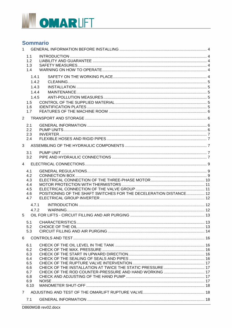
Operate as follows to get rid of the air completely (see Figure 9).
TOTAL AMOUNT OF OIL IN THE CIRCUIT = A+B x TRAVEL (m) + C x LENGHTH (m)
1- OIL FOR TANK = “A” CAPACITY
TANK TYPE 110 210 320 450 680
CAPACITY “A” - LITRES 100 200 305 430 650
2- OIL FOR CYLINDER (FOR THE FILLING UP WITHOUT TRAVEL) = “B”
ROD DIAMETER
mm
50 60 70 80 90 100 110 120 130 150 180 200 230
OIL “B” l/m 3.1 4,5 5 3,8 5,7 5,6 6,4 6,1 8,5 8,3 15,6 18,9 19,4
3- OIL FOR CONNECTION PIPES = “C”
PIPE Ø22 x 1.5 flex ¾” Ø35 x 2.5 flex 1¼” Ø42 x 3 flex 1½” N° 2 tubi x Ø42 x 3 Flex 2”
OIL “C” l/m 0,30 0,70 1,00 2,00 1,90
1) Unscrew completely and remove the purge screw on the head of the cylinder (or cylinders).
2) If the rupture valve is not adjusted (red label on it), its regulation screw has to be unscrewed.
3) With pushbutton maintenance, make a call breathes (low speed).
4) Carry out an upward start and check the direction of rotation of the motor. If the direction of
rotation is wrong, a pump cavitation noise will be heard. It shall then be necessary to exchange
two phases on the motor connection.
5) Keep the motor activated for 10 – 15 seconds and stop it for 20 - 30 seconds to allow the air to
go out.
Repeat this operation several times, until only oil, without air, comes out from the purge screw.
6) Close the purge screw of the cylinder and adjust the rupture valve, in case it has not been
adjusted previously in the factory.
If the rupture valve needs to be adjusted, carefully follow the operating instructions enclosed to it,
or the directions in chapter 7 "ADJUSTING AND TEST OF THE OMARLIFT RUPTURE VALVE".
7) Reset the oil level in the tank, if necessary and make an upward travel at low speed, checking
that all the parts of the installation are in order and that the oil quantity is sufficient. The motor
has always to be covered by oil even when the cylinder is at the upper end.
Avoid that the oil level decreases until it uncovers the motor-pump group.
In this case in fact the pump could suck air, making all the above purging operations void.
8) Check that in the circuit there is no remaining air. At this purpose, stop the car on an intermediary floor, close the shut-off valve and turn off the power, get into the car and check that there is no strong lowering, get off the car and verify that the car does not go quickly back to its initial position.
D860MGB rev02.docx 16/32
Figure 9 – Position of Screws for purge and for the rupture valve regulation
6 CONTROLS AND TEST After the assembling operations have been completed, after the oil has been filled and the air has been
purged from the circuit, it is proper to make the following checks:
6.1 CHECK OF THE OIL LEVEL IN THE TANK
When the cylinder is in upper end position, check that the oil level in the tank covers the motor-pump
group well (min. 2 cm over the motor).
When the cylinder is in lower extra-travel position, the oil level has to be 7/8 cm under the tank edge.
6.2 CHECK OF THE MAX. PRESSURE When the main line shut-off valve is closed, the motor activated for the upper travel, the oil
discharges into the tank and the manometer shows the max. adjusting pressure of the overpressure
valve.
The value of the max. adjusting pressure has to correspond to 1,4 times the max static pressure with
full load.
6.3 CHECK OF THE START IN UPWARD DIRECTION In order to get a smooth start of the motor in upward direction without load, be sure that:
When the shut-off valve is closed, discharge pressure using the emergency button and start up the
motor again: check that the pressure rises slowly from its minimum to its maximum value.
If necessary, adjusting the parameters of the inverter.
6.4 CHECK OF THE SEALING OF SEALS AND PIPES Check visually the connection pipe sealing, in particular the joints of the flexible hoses and rigid pipes.
After some travels, the rod looks covered by a small quantity of oil needed for its lubrication.
A possible oil ring on the rod could appear in the first working days because of deformation or hardening of
the seal, in particular if the cylinder has remained laid down for a long time on the site.
This phenomenon will disappear after a short period of time. Only if there is a huge oil quantity in the
recovery tank, it will be necessary to replace the seals.

D860MGB rev02.docx 17/32
6.5 CHECK OF THE RUPTURE VALVE INTERVENTION Be sure that the rupture valve has already been adjusted. If necessary, regulate it according to the handbook
for the adjusting operations or the instruction reported.
The down travel intervention test has to be carried out when the car has been loaded with the nominal load
uniformly distributed according to the instructions reported in paragraph 7.2 "TEST AND WORKING OF THE
RUPTURE VALVE".
6.6 CHECK OF THE INSTALLATION AT TWICE THE STATIC PRESSURE This check has to be carried out only after the check of the rupture valve intervention and when the oil
temperature is constant.
The oil has not to be hot: the test has to be carried out only when the oil temperature is the same as the
room temperature (please note that in a close circuit, the temperature variation of 1°C can cause a pressure
variation of 9 bar):
- If necessary, determine the max. static pressure loading the car with the nominal load.
- Take the piston to upper end position with the main motor until the adjusting pressure is reached and
stop in this position.
- Increase the pressure slowly with the hand pump until double the max. static pressure.
- Check pressure fall and losses within 5 minutes, taking into account the possible effects due to the
oil temperature variation. If necessary, repeat the test, re-charging the pressure for 2/3 times with the
hand pump, controlling that pressure does not decrease by 5/6 bar during the first 4/5 minutes. If
needed, read paragraph 10.10. “Periodical recommended maintenance sheet”.
- When the test has finished, take back the pressure to the value of the static pressure, activating the
emergency button manually and control visually the integrity of the hydraulic system.
6.7 CHECK OF THE ROD COUNTER-PRESSURE AND HAND WORKING - For indirect acting installations 2:1, check that, when the car is blocked on the proper parachutes or
lays on its dampers, by activating the red emergency button, the rod does not go down making the
ropes loosen. If necessary, screw the screw n. 3 until it stops.
- For any kind of installation, check that, when the car is free to go down, it goes down regularly at a
reduced speed when the emergency button is pushed.
6.8 CHECK AND ADJUSTING OF THE HAND PUMP When the main shut-off valve is closed, activating the hand pump, the pressure on the manometer has to
increase up to the adjusting value.
The safety valve of the hand pump has to be adjusted at 2,3 times the static pressure of the installation with
full load.
The regulation screw of the hand pump is on the left of the lever. If necessary, see instructions at point 8.3.3
for the regulation.
6.9 NOISE The noise of OmarLift pump units is normally very low, especially during transistors (start / slowdown
example).
With average working conditions, when oil temperature is at 30/40°C and pressure at 25/30 bar, noise does
not normally exceed the following values:
pump unit up to 210 l/min: 56÷58dBA
Anyway some external causes can determine an increase in the noise transmission of the installation: in fact
the noise is sometimes transmitted or even expanded by the building walls or by the connecting pipes, thus
reaching the lift space or the rooms next to it. When it happens it is necessary to operate as follows:
1) Use some thick rubber to isolate the connecting pipes from collars used to fix the pipes to the walls.

D860MGB rev02.docx 18/32
2) Use some thick rubber to isolate both the cylinder head from its fixing collar and the cylinder bottom
from its support.
3) To connect the pump unit to the cylinder use a piece of flexible hose placed near the pump unit
which has to be at least 5/6 meters long.
4) Add some oil in the tank up to the maximum level allowed.
5) Make sure that the pipe discharging oil from the valve to the tank, always discharges under the tank
oil level.
6) Check that there is no air in the oil.
6.10 MANOMETER SHUT-OFF The manometer, which is placed on the valve group, is supplied with an exclusion shut-off. During the
regular working of the lift, the manometer shut-off has to be perfectly closed to avoid possible oil losses or
damage to the manometer itself.
7 ADJUSTING AND TEST OF THE OMARLIFT RUPTURE VALVE
7.1 GENERAL INFORMATION - The rupture valve is the hydraulic parachute assembled on the cylinder. It operates against the free
fall or the down travel with an excessive speed.
- The rupture valve has to be capable to stop the car during the down travel and keep it still, when the
downward speed exceeds the nominal speed +0,3 m/s at the latest.
- Practically it is possible to fix a speed increase corresponding to 30% of the nominal speed. This
value covers all the applications until the max admitted speed for hydraulic installations: 1 m/sec.
- The car speed changes with the variation of the oil which goes through the valve: adjusting a valve
means limiting the passage to a minimum value which lets an oil quantity, lower than the adjusting
value, run free and blocks the oil flow when the adjusting value is reached.
For the calibration procedure, the appropriate manufacturer's manual.
7.2 TEST AND WORKING OF THE RUPTURE VALVE
a) Get the travel shaft free and be sure that the whole lift equipment is perfectly working.
b) Load the car with the nominal load and take it to the upper floor.
c) Activate the test parachute valve (VP) of the inverter.
d) Make a travel from the upper floor to the lowest one.
e) The car speed increases up to exceeding the nominal speed..
f) The rupture valve intervenes when the downward speed increases by 30% about with respect to the
nominal speed. As a result, the car decelerates up to stop.
g) If, after some-meter run at a speed higher than the nominal one, the rupture valve has not
intervened, stop the car pushing button "STOP"..
h) The trial function VP is automatically disabled after each test. To repeat the trial restart from point C.
i) When the test has finished, block the regulation screw with the lock nut and seal with red paint or link
the two proper holes, one located on the screw and the other on the valve block, with iron wire and plumb.
8 VALVE GROUP AND INVERTER’S PARAMETER CALIBRATION AND
ADJUSTMENT
8.1 GENERAL INFORMATION The valve group is adjusted and tested in the factory together with shut-off valve, motor pump group and
inverter. When the regulation has been completed, a diagram is prepared which reproduces the speed
behavior during upward and downward travels. This diagram (see Figure 10) is supplied together with its

D860MGB rev02.docx 19/32
pump unit. The identification plate (see Figure 11) lays on the pump unit cover and shows the valve drawing,
all the regulation points, the description of the electro-valves and all identification data.
Before any regulation of the valve or the inverter, verify:
- all the electrical connections have been carried out correctly.
- the oil in the tank is the advised one and it temperature is between 20 and 30°C.
Figure 10 - Upward and downward speed diagram
Figure 11 - Identification plate
8.2 HYDRAULIC SCHEME
Figure 12 - OmarLift HI valve: hydraulic circuit (without A3 device)

D860MGB rev02.docx 20/32
8.3 ADJUSTING AND REGULATION OF “HI” VALVE GROUP
SCREW DESCRIPTION REGULATIONS
N° 1 Adjusting of the max pressure valve screw to increase max pressure unscrew to decrease max pressure
N° 3 Rod counter-pressure and rope anti-loosening device adjusting
screw not to make the rod drop in emergency unscrew to make the rod drop in emergency
N° 9 Hand pump pressure adjusting screw to increase the hand pump adjusting pressure unscrew to decrease the hand pump adjusting pressure
OVER-PRESSURE VALVE CALIBRATION: SCREW N°1 8.3.1
The over-pressure valve has to be adjusted with a pressure 1,4 times the max. static pressure with a
full load. (Higher values, corresponding max to 1,7 times, are also admitted, only if this possibility
has been taken into account during the project phase).
The max pressure is reached only when the piston is in upper end position or when the main line valve is
closed.
- Close the shut-off valve of the main line and open the manometer valve.
- Screw the screw n. 1 and discharge the possible pressure with the red manual emergency button.
- Start the motor in up direction.
- Screw the screw n. 1 until the max wanted pressure value is reached and stop the motor.
- Discharge again pressure with the hand button, activate the motor checking that the manometer
shows the adjusted pressure, block the nut and stop the motor.
In case the given pressure needs to be decreased, discharge the pressure with the hand button,
unscrew the screw n. 1 and repeat the adjusting.
ROD COUNTER-PRESSURE AND ROPE ANTI-LOOSENING CALIBRATION: SCREW N. 3 8.3.2
For security reasons, in indirect acting installations, the activation of the emergency button has not to
cause the rope loosening when the car is locked. For this reason, it is necessary that, inside the

D860MGB rev02.docx 21/32
circuit, there is a remaining pressure higher than the pressure generated by the weight of the rod, the
pulley and the ropes. This pressure is regulated by screw n. 3: screw, it increases; unscrew, it
decreases. The value of the counter-pressure which opposes the rod down travel is about 6/8 bar
Adjust the counter-pressure as follows (see Figure 13):
- Close the main shut-off valve and discharge pressure with the hand button. The remaining pressure
on the manometer corresponds to the rope anti-loosening counter-pressure.
- If the pressure value needs to be increased or decreased, screw or unscrew the screw n. 3
accordingly.
If the input pressure needs to be verified:
- Increase the pressure in the circuit with the hand pump;
- Discharge the pressure with the hand button and read the remaining pressure;
- If necessary, repeat the previous operations until the wanted counter-pressure is reached.
Figure 13 - Adjusting of the rod counterpressure
CALIBRATION OF THE HAND PUMP PRESSURE: SCREW N. 9 8.3.3
The hand pump has a safety valve which has to be adjusted at 2,3 times the max static pressure. The
adjusting is carried out through screw n. 9: screw, the max pressure increases, unscrew, it decreases (see
Figure 14). In case there are difficulties in activating the hand pump, close the main shut-off valve, unscrew
the screw n. 3, discharge the pressure with the hand button and quickly activate the hand pump lever. If
necessary, try to fill with oil the plastic pipe which gets inside the tank.
Figure 14 - Adjusting of the hand pump pressure

D860MGB rev02.docx 22/32
- Act on screw n. 9 to adjust at the right pressure and activate the hand pump lever. The adjusting
pressure of the hand pump is the max one reached and shown on the manometer.
- Discharge the pressure with the emergency hand button.
CALIBRATION OF THE PRESSURE SWITCHES (PRESSURE MIN. - MAX. - OVERLOAD) 8.3.4
In case a pre-determined pressure is reached inside a pressure switch, an electrical contact, which can be
switching, opening or closing, is activated. Pressure switches with different insulating classes, different
precision levels or different hysteresis are also possible.
The following drawings show three types of pressure switches and two types of contacts. The regulation of
the intervention pressure is obtained through single- slot screw which lays in the center of the pressure
switch (see Figure 14).
Turn clockwise, the intervention pressure increases, turn anti-clockwise, it decreases.
The pressure switch is assembled on the valve block and lays directly on the pressure line which gets to the
cylinder, before the piloted rupture valve VBP, consequently it is always under pressure.
Adjust the pressure switch as follows:
- Close the main shut-off valve.
- Discharge the pressure with the hand button
- Take the pressure to the wanted value using the hand pump
- Connect a tester to the pressure switch contacts
- Act on the regulation screw of the pressure switch, until a contact exchange is obtained.
Figure 15 – Limit switch

D860MGB rev02.docx 23/32
8.4 INVERTER SETTING AND PROGRAMMING Refer to the manual inverter supplied and / or to the manual of the manufacturer.
9 OPTIONAL ACCESSORIES
9.1 OIL HEATING RESISTANCE (optional) - The resistance to be installed in the tank to heat the oil is 500WATT powerful. Its feeding tension can
be 220/230V - 50Hz or 380/400V - 50Hz.
The resistance for the heating of the oil supplied has a non-adjustable thermostat set at about 30°C.
The result is better if you return to the ground floor the cabin after the first 8-15 minutes of non-use of
the system.
The Figure 16 shows the installation of the oil heating resistance in the tank.
Figure 16 - Position of heating resistor
9.2 OIL COOLING (optional)
GENERAL INFORMATION 9.2.1
Generally oil needs to be cooled in installations with high traffic or for workplaces particularly critical
According to the different situations, it is suggested to use an oil cooling system in installations with more
than 50/70 travels per hour. The oil cooling system can be with air or with water and is available in two sizes:
from 6kW to 21kW.
The main parts of an oil cooling system are:
- An electro-pump for the forced oil running;
- An heat exchanger (oil/air - oil/water)
- A thermostat to control the temperature;
The following table suggests how a cooling system mas to be chosen:
PUMP UNIT MOTOR TYPES OF COOLING SYSTEMS
Up to 13 HP = 9,6 kW 6 kW = 5160 kcal/h
To 15/30 HP = 11/22 kW 10.5 kW = 9000 kcal/h
More than 30 HP = 10/22 kW 21 kW = 18000 kcal/h
The thermal exchange values, in kW or in kcal /h, refer to 30°C temperature differences between oil and the
exchange fluid (air / water) (eg. Oil 50°C - air or water 20°C).
Obviously, if the temperature difference between oil and air / water is less than 30°C, the thermal exchange will be lower too.

D860MGB rev02.docx 24/32
An incorrect sizing may result in inadequate oil overheating and malfunction in the system.
COOLING SYSTEM WITH AIR 9.2.2
The Figure 17 shows the connection diagram between pump unit and heat exchanger.
The air heat exchanger has not to be put near the oil tank. The air heat exchanger has to suck fresh air and has to be put preferably near a window or an air
passage connected to the outside.
The room where the heat exchanger has been located, has to be constantly ventilated.
The heat exchanger has to be positioned preferably on the same floor as the pump unit, about 3 m
far from the tank.
Noise is 68/71 dB(A) about.
For further information see the technical catalogue or the specific operating instructions
COOLING SYSTEM WITH WATER 9.2.3
The cooling systems with water are generally connected directly to the tank when the pump unit is being built
(see Figure 18).
If the cooling system with water is supplied alone - without pump unit - the customer will have to connect it to
the pump unit.
The holes for the oil suction have to be as far as possible from the holes for fresh oil return to the
tank. While the hole for the thermostat has to be close to the hot oil suction.
The water connections have to respect the measures shown by Figure 18, or the real ones in the installation.
- Noise will be lower than 60 dBA.
- For further information see the technical catalogue or the specific operating instructions.
Figure 17 – Example of connection diagram of the oil cooling system with air
Figure 18 - Example of connection diagram of the oil cooling system with water. A value is 165mm (10,5KW) or 215mm (21KW)

D860MGB rev02.docx 25/32
10 MAINTENANCE
10.1 GENERAL INFORMATION Generally, the hydraulic components are not subject to a frequent wear, they are safe and need few
maintenance operations. These results are reached when the components are chosen and dimensioned
correctly on the basis of the installation characteristics. Moreover the hydraulic oil has to suit with the room
temperature and the installation traffic conditions.
It is however necessary to make, according to the established times, the test and maintenance operations reported in the periodical recommended maintenance sheet and get rid of the detected faults immediately.
In case irregularities or faults, which can jeopardize the safety of people and installations, are met on
the components, the installation has to be put out of service until the defective parts are repaired or
replaced.
10.2 OIL LOSSES AND CAR LOWERING Oil losses in the hydraulic circuit cause the car lowering with respect to the floor level even when controls,
which make the electrical re-leveling intervene, are absent.
Please remember that the car lowering can also be caused by the oil cooling.
This phenomenon is evident when the installation stops, oil is very hot and the room temperature is
much lower than the oil one.
At these conditions the electrical anti-creep system has no to be deactivated, since the car lowering
could be very important.
Oil losses in the hydraulic circuit can be due to the following causes:
LOSSES ALONG THE PIPES 10.2.1
Losses are usually localized in the joints of the rigid pipes or along the flexible hoses. These losses can be
visually detected. They can be eliminated tightening the fitting nuts, joining the pipes correctly or replacing
the flexible hoses.
CYLINDER LOSSES 10.2.2
Big cylinder losses are due to wear or to damaged seals, which are located in the head of the cylinder itself.
The oil coming out from the cylinder is collected in a proper room and, through a PVC pipe, conveyed to a
transparent tank. It is necessary that the room inside the cylinder head and the hole leading to the PVC pipe
are not obstructed by dirt. The cylinder losses depend on the traffic intensity and seal wear.
When losses are more than one or two liters per month, it is better to replace the cylinder seals.
In underground direct acting cylinders, oil losses can be due to chemical or electrical corrosion of the
cylinder. This phenomenon provokes the continuous decreasing of the oil level in the tank.
Underground cylinder have to be put inside a protection wrapping to avoid ground and groundwater
pollution.
In case oil soaks into the ground, the underground cylinder has to be disassembled and replaced.
LOSSES INSIDE THE VALVE GROUP 10.2.3
When the installation is motionless at floor and the electro-valves are disconnected, the load pressure
involves the part of the valve shown in Figure 19 with black colour.
The valve sealing is proved as follows:
- When the valve temperature is the same as the room temperature, close the main line shut-off valve
and increase the pressure, using the hand pump, until twice the static pressure;
- If there are no losses in the valve, pressure keeps constant or decreases slowly, not more than 5/6
bar during the first 3/4 minutes and tends to settle;

D860MGB rev02.docx 26/32
- If there are losses in the valve, pressure decreases rapidly, more than 5/6 bar during the first 3/4
minutes and goes on decreasing up to the static pressure value;
- The valve components which can be involved in possible losses are the following:
a) Hand pump.
The hand pump sealing is assured by a ball. Activate the hand pump, leave the lever against the valve and
wait for some minutes to check the sealing. In case of losses, the lever goes back automatically.
Repeat the test for some times to be sure that the loss is not caused by dirt particles laying between seat
and ball. If necessary, replace the hand pump.
Figure 19 - Part of the valve remaining under pressure when the installation is still (in black)
b) Hand emergency valve VEM.
The sealing of the hand pump is also assured by a ball whose working can be jeopardized by dirt laying
between seat and ball. Carry out a first check by removing the moving half-cover of the tank and look under
the valve. Every time the emergency button is activated, an oil outflow will be noted.
This outflow has to stop when the button is left. In case this does not happen, there can be losses from the
emergency valves or losses from the electro-valve EVD which has the same discharge point.
The following checks must be carried out with pressure inside the valve. It shall be therefore
necessary to act with due caution. In order to check the sealing of the emergency valve (see Figure 20), it
will be necessary to remove the coil, unscrew the mechanical part of the coil, remove the pin, carefully dry
the residual oil left inside the seat and make sure that no other oil leaks out.
If oil losses are noticed it shall be necessary to replace the whole downward travel block or carry out a
repair as described as follows.

D860MGB rev02.docx 27/32
Close the main line shut-off, unscrew screw no. 3 (rod counterpressure) and press the manual
emergency button in order to lower the pressure to zero.
- Unscrew the fixing screws of the block to inspect the ball seats.
- Remove the seeger which blocks the spring and the ball.
- Inspect the seats and if they appear grooved or faulty, attempt to repair them by repositioning the
balls in their proper place and clinching them by using a proper punch.
Warning: do not hammer strongly because the seat is in aluminum, and may damage or break
through. If possible, replace the balls used to clinch the seats.
- Reassemble all the components properly, reassemble the block and check the sealing.
Figure 20 - Check of emergency valve working
c) Down travel electro-valve EVD.
The sealing ball of the down travel valve (see Figure 21), can remain slightly open and loose oil.
The following checks must be carried out without pressure inside the valve. It shall be therefore
necessary to close the main line shut-off, unscrew screw no. 3 (rod counterpressure) and press the
manual emergency button in order to lower the pressure to zero.
The reasons why the downward travel valve may not work properly are the following:
- Small metal particles or dirt have got inside the coil between the tube and the cursor delaying or
preventing the return movement of the coil cursor.
It is necessary to remove the coil, unscrew the mechanical part of the EVD and shake it backwards
and forwards with the hand to insure that the inside piston is free. If not, replace it.
- The EVD coil button has got caught after having been manually activated with a screwdriver and the
coil cursor cannot return to its resting position. In this case it is necessary to remove the coil,
unscrew the mechanical part of the EVD and push its piston completely back.
- Some metal particles lay between the ball and the sealing seat preventing the closing or damaging
the sealing seat of the EVD valve. To check the EVD electro-valve sealing it is necessary to remove
the coil, unscrew the mechanical part of the coil, remove the pin and the EVD aluminum valve.
At this point it is necessary to inspect the EVD valve and then proceed in the following way:
- Remove the seeger which blocks the spring and the ball in the lower part of the EVD valve.
- Inspect the ball seat and if it appears grooved or faulty, attempt to repair it by repositioning the ball in
its proper place and clinching it by using a proper punch.

D860MGB rev02.docx 28/32
Warning: do not hammer strongly because the seat is in aluminum, and may damage or break
through. If possible, replace the balls used to clinch the seats.
- Reassemble all the components properly, reassemble the EVD valve in its seat, the pin and the coil.
Reactivate the valve pressure by opening the shut-off valve and verify that there are no losses
underneath the valve.
If oil losses are detected it will be necessary to replace the EVD valve or the whole downward travel
block.
d) Piloted non return valve VBP
Figure 21 - Downward electrovalve EVD
The VBP valve (non-return valve) has to keep the main line closed when the car is motionless. The perfect
sealing is guaranteed by a seal laying between the two parts which compose its piston.
This seal wears with the passing of the time and can be damaged by metal particles which engrave it and
hinder its sealing because they come between seat and seal.
The closing can also be slowed by the bad running of the VBP piston because of dirt and hindered by the
faulty closing of the electrovalve EVD.
Operate as follows to get rid from VBP losses :
Close the main line shut-off valve.
Unscrew the screw n. 3 for rod counter-pressure and take pressure back to zero using the
emergency descent button.
Remove the cover to reach VBP piston.
Check that VBP piston runs well and, if necessary, remove dirt and clean with a thin cloth.
Replace the VBP seal as shown in Figure 22:
Unscrew the screw which holds the two parts of the piston tight and replace the seal laying between
them. Be careful to position it in the right way.
Reassemble all the parts paying attention to the O-Ring which lays between the valve and the cover.

D860MGB rev02.docx 29/32
Figure 22 - Replacement of seal VBP and cleaning of the filters
10.3 AIR PRESENCE IN THE OIL There is air in the oil in case of foam in the tank mainly during the down travel phase and in case the oil
becomes whitish.
Negatives effects on the installation are caused by the increase of the oil compressibility factor.
The most common effects are the following ones:
- When the installation is motionless at the floor, the car lowers when loaded and goes up when
unloaded.
- When the installation moves, strong oscillations, pump noise and irregularities during the movement
are noted.
- Air in the oil can be due to: insufficient air purge during the first filling of the circuit, too low level of oil
in the tank, the discharge pipe is not connected to the valve any more, etc.
Operate as follows to get rid of the air from the circuit:
- When the oil is hot, position the car low on the dampers and discharge pressure with the hand button,
unscrewing the screw n. 3 of counter-pressure too.
- Remove the cylinder vent screw and leave everything rest for about 8/10 hours. In this way the air in
the oil will go up and the air in the tank will be automatically released. Now, purge the air from the
cylinder: see paragraph. 5.3.
10.4 FILTER CLEANING INSIDE VALVE GROUP - With a general overhaul or when operation faults occur, clean all filters located on the electro-valves and
indicated in the Figure 22.
- To clean or replace the cartridge of the shut-off valve filter, before closing the shut-off valve, unscrew screw
no. 3 and discharge the pressure, then unscrew the bottom of the filter to reach the cartridge.
10.5 MINERAL OIL DETERIORATION It is difficult to calculate how fast the mineral oil deteriorates: this time depends on the work conditions, such
as temperature, humidity and pressure, and from the real working hours.
-Dust and moisture in the environment get into the oil directly or because of condensate through the air
which enters into the tank during the up travel phase. They can deteriorate oil very fast.
-Pressure and temperature in the hydraulic installations are not so high and do not have a negative influence
on the oil life, unless the oil itself is continuously subject to overheating or the motor burns inside it.

D860MGB rev02.docx 30/32
-The real working hours of a good oil, without the above mentioned factors, go from 3000 to 5000 max. about.
These limits are however influenced by the two above mentioned factors.
-Every year at least and however every 2000 working hours, check the oil preservation condition: smell, color,
foam, dirt particles, etc. If necessary, contact a specialized analysis laboratory.
In case the oil needs to be replaced, pay attention to the anti-pollution regulations in force
10.6 ELECTRICAL ANTI-CREEP SYSTEM (RE-LEVELING) During controls on the installation, check the working of the anti-creep system, activating the hand
emergency at every floor and, re-leveling occurred , the hand pump (check relevelling downward)
10.7 EMERGENCY LOWERING WITH THE BATTERY Check periodically the battery efficiency, switching off the feeding tension.
10.8 PLATES, DIAGRAMS, INSTRUCTIONS Check periodically the presence of plates, diagrams and instructions where requested.
10.9 INVERTER MAINTENACE To ensure long service life and smooth operation of the drive, carry out the following checks at regular
intervals.
Always isolate the drive from the power supply and make certain the keypad is off before proceeding
Remove the dust that collects on the cooling fans and on the control circuit board, preferably by means of
compressed air or using a vacuum cleaner.
Check that there are no screws loose at the power or control terminals.
Check that the operation of the inverter drive is <<normal>> and that there are no signs of overheating.
MEGGER TEST 10.9.1
When performing insulation tests using a Megger tester on the input/output cables or on the motor,
remove all the connections to all terminals of the drive and perform the test only on the power circuit,
in accordance with the adjacent diagram. Do not Megger test the control circuits..
10.10 RECOMMENDED PERIODIC MAINTENANCE
PERIODICAL RECOMMENDED MAINTENANCE OPERATIONS
FOCUS ON THE OPERATING INSTRUCTIONS FOR THE PERIODICAL MAINTENANCE
INSTALLATION COMPLETED
EVERY 2-3 MONTHS
EVERY YEAR
EVERY 5-10 YEARS
CHECK OF THE SEALING OF THE CYLINDER SEALS
10.2.2 10.2.2
CHECK OF THE SEALING OF THE VALVE SEALS
10.2.3 10.2.3
CHECK OF THE PIPE SEALING
10.2.1 10.2.1
CHECK OF THE OIL LEVEL AND 6.1 6.1 6.1

D860MGB rev02.docx 31/32
PRESERVATION
CLEANING OF THE SHUT-OFF VALVE AND VALVE FILTERS
10.4 10.4
CHECK OF THE PRESSURE AND ADJUSTING AT TWICE THE MAX STATIC PRESSURE
6.2 6.6
6.2 6.6
CHECK OF THE RUPTURE VALVE WORKING
7.2 7.2
CHECK OF THE ROPE ANTI-LOOSENING COUNTER-PRESSURE
6.7 6.7
CHECK OF THE ELECTRICAL ANTI-CREEP SYSTEM
10.6 10.6
CHECK OF THE EMERGENCY AND BATTERY
10.7 10.7
PLATES – DIAGRAMS – INSTRUCTIONS
10.8 10.8
GENERAL OVERHAUL
XXXX
CLEANING OF THE INVERTER FAN
10.9 10.9
CHECK OF THE ELECTRICAL INVERTER CONNECTION
10.9
11 DIMENSIONS AND WEIGHTS
11.1 DIMENSIONS AND WEIGHTS OF THE PUMP UNITS The weights of the pump units with shut-off valve are divided per kind of tank and do not consider the weight
differences of pumps and motors of different size. Consequently there is a are approx. calculated with a 5%
tolerance.
TANK TYPE TANK BASE (HANDLES INCLUDED) MM
HEIGHT (TANK + VALVE) MM
PUMP UNIT WEIGHT (OIL EXCLUDED) KG
110 774 x 300 702 + 260 105
135 774 x 300 702 + 260 110
210 904 x 400 810 + 260 145
320 1024 x 460 950 + 260 176
450 1074 x 700 952+ 270 230
11.2 DIMENSIONS AND WEIGHTS OF INVERTER AND RESISTORS Refer to the manual of the inverter.

OMARLIFT s.r.l. Via F.lli Kennedy, 22/D 24060 Bagnatica (BG) – ITALY Phone +39 035 689611 Fax +39 035 689671 Email: [email protected] Web: http://www.omarlift.eu


