The DC-02 system has been designed as part of a retro-fit system for automatic sliding doors. The basic system consists of a controller module that provides the interface with the drive motor and pulley, auxiliary battery and all sensors. A second module provides the power supply of 24v ac from mains 230v ac supply. The drive system consists of a Dunker GR63-55 motor, SG80 worm drive gearbox, drive pulley and ME52/12 shaft encoder. Although the DC-02 has been designed primarily for this motor/ gearbox/encoder combination it has the flexibility to accept other motor gear box combinations if desired. The kit also comprises a 24v, 1.2Ah battery pack and programme key-switch. In order to obtain the full potential of the DC-02, the system to which the kit is to be retrofitted must be compatible, mechanically sound and free running, with door weights within the specified limits for DC-02
2. SAFETY INSTRUCTIONS The DC-02 has been designed according to current standards and technical safety regulations, including, for example, limiting of forces and speeds. It may be dangerous to use it for applications other than that for which it is intended. Installation, maintenance and repairs to the DC-02 should only be performed by qualified and authorized personnel. The DC-02 is designed purely for use on automatic sliding doors. The installation should be under cover and not exposed to an outside environment. Any use other than the above is deemed to be other than its intended purpose. As such the manufacturer cannot accept any liability for any subsequent damage. The operator must be aware of the operating conditions of the manufacturers specification and must ensure regular care maintenance and repair. Unauthorised modification to the DC-02 system will invalidate all warranties. The system must always be run with safety sensors connected During the initial learning cycle all sensors, including safety sensors, are switched off. Care must, therefore be taken that no persons or objects are present in the danger zone during this operation. The installation is not intended to be disconnected from the mains at night. EC DECLARATION OF CONFORMITY We Triton Controls Ltd 2 Randolph Industrial Estate Evenwood Bishop Auckland, Co. Durham DL14 9SJ Declare that the DC-02 Retrofit controller for automatic sliding doors Conforms to the requirements of the EMC Directive 89/336/EEC and the Low Voltage Directive 73/23/EEC We further declare that the machinery into which it is to be incorporated, or to which it is to be a component, should conform to the provisions of Directive 98/37/EC P. Clarke, Technical director
3. SPECIFICATION
3
3.1 User Interface
Manual adjustment of operating parameters, via push buttons with on-board LCD display. All parameters stored in non-volatile memory.
Impulse push button to initiate door opening cycle Reset push-button to initiate a full system reset. ( also by remote facility). System switch------4 position key switch. CLOSED, OPEN, EXIT ONLY, AUTOMATIC Optional 2 position Morning Entry switch.
3.2 Power Supply
Input Nominal 230v ac mains, 50 to 60 Hz Output Nominal 34v DC motor supply Emergency battery 24V, 1.2Ah Operating Temperature -20°C to +50°c
3.3 Controller On board features
Liquid crystal display with 2 lines of 16 characters Pushbuttons for RESET, IMPULSE, ENTER, INCREMENT, DECREMENT & ESCAPE Audible warning Battery conditioning & monitoring
Outputs-
Motor, reversible 0 to 34V DC PWM speed control Lock solenoid, programmable 12V or 24V DC and for powered ON (FAIL SAFE) or
powered OFF ( FAIL SECURE) *Relay. Configured to supply HZ-C ultrasonic presence sensor initialisation (self-teaching)
pulse. *HZ-C-CS, constant sensing presence sensor, self test pulse output
* Note. The last 2 items apply when HZ-C-CS presence sensor is fitted in lieu of safety beams. The self-test feature enables the HZ-C-CS to meet the self test requirements of the proposed EN norm for safety of automatic doors.
+24V 1A DC supply for sensors. +5V DC supply for motor encoder
Inputs
Encoder quadrature inputs Activation sensor 1 –inside (normally OPEN) Activation sensor 2—outside (normally OPEN) Hold -- Holding beam or HZ-C presence sensor input (normally CLOSED) Side screen sensor(s)—Can support integral buzzer sensors ( HR94-TBC) or
Standard sensor with relay output providing signal to initiate alarm and creep motion. Morning entry—momentary key switch Fire Alarm (NORMALLY CLOSED) Emergency Stop (NORMALLY CLOSED) Reset System switch------4 position key switch. CLOSED, OPEN, EXIT ONLY, AUTOMATIC
4
4. OPERATING INSTRUCTIONS AND CONTROL FUNCTIONS
4.1 System switch The function switch is fitted with a 4 position rotary key switch, which is used to set the various modes of operation.. The key switch can be withdrawn in any position. Modes of operation
AUTOMATIC. This is the standard operating mode. The door is actuated by the actuation of Sensor 1 or Sensor 2, the approach sensors, or by pressing the “Impulse” button on the key pad. The door closes again after the hold open time has expired.
OPEN. The door remains continuously open.
CLOSED. The door remains continuously closed and, (if a lock is fitted and
programmed), locked. EXIT ONLY. The door operates in automatic mode, but in one direction only.
Activation is. by the internal approach sensor or by the optional key-operated Morning Entry Switch. If a lock is fitted and programmed the doors are locked in the closed position.
RESET BUTTON. A system reset may be effected by pressing the small push button on the function key switch for approximately 10 secs, when the function switch is set to “OPEN”
AUTO
EXIT ONLY
OPEN
CLOSED
5
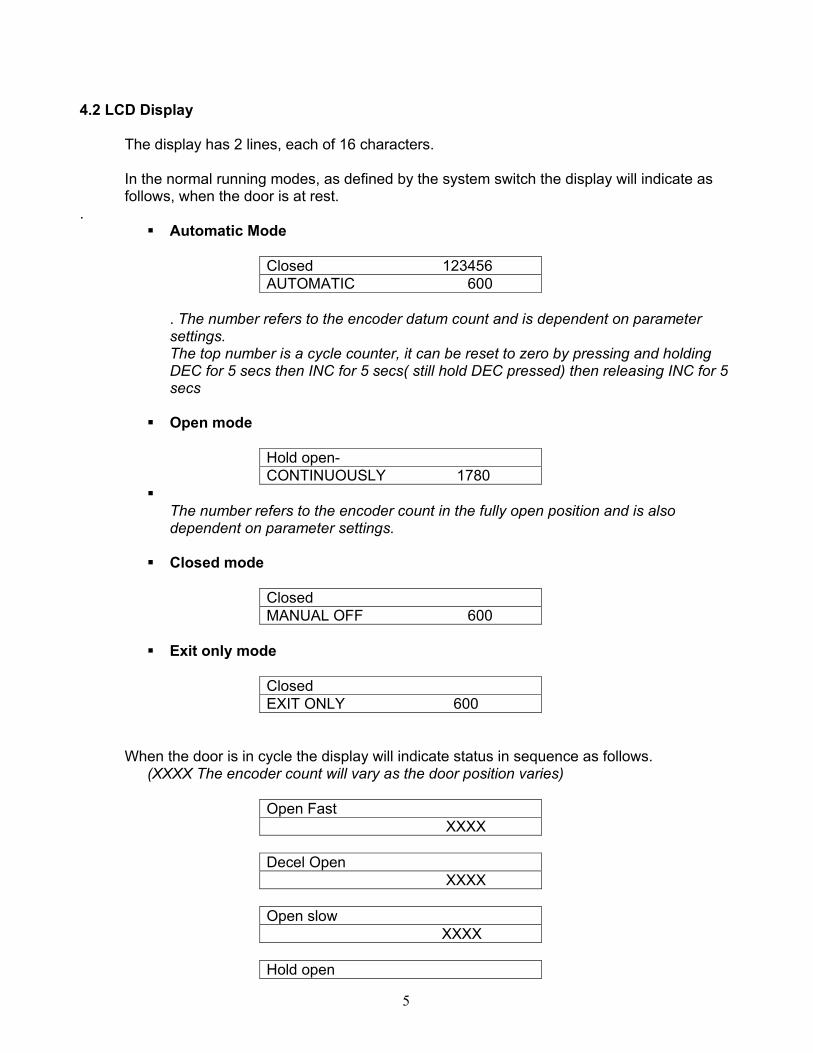
4.2 LCD Display
The display has 2 lines, each of 16 characters. In the normal running modes, as defined by the system switch the display will indicate as
follows, when the door is at rest. .
Automatic Mode
Closed 123456 AUTOMATIC 600
. The number refers to the encoder datum count and is dependent on parameter settings. The top number is a cycle counter, it can be reset to zero by pressing and holding DEC for 5 secs then INC for 5 secs( still hold DEC pressed) then releasing INC for 5 secs
Open mode
Hold open- CONTINUOUSLY 1780
The number refers to the encoder count in the fully open position and is also dependent on parameter settings.
Closed mode
Closed MANUAL OFF 600
Exit only mode
Closed EXIT ONLY 600
When the door is in cycle the display will indicate status in sequence as follows.
(XXXX The encoder count will vary as the door position varies)
Open Fast XXXX
Decel Open XXXX
Open slow XXXX
Hold open
6
Time XX (Where XX is the hold open count down in secs)
Close Fast XXXX
Decel Close XXXX
Close slow XXXX
If for any reason the door cycle is interrupted the LCD will display the following
Obstruction!
Followed by either,
Open slow XXXX
if the door was obstructed on closing. Or,
Close slow XXXX
if the door was obstructed on opening
After being obstructed the door will operate in creep mode on the first part of the subsequent cycle and the display will read:
Creep obstruct XXXX
It will also display the above message if the side screen sensor detects presence on the opening stroke.
7
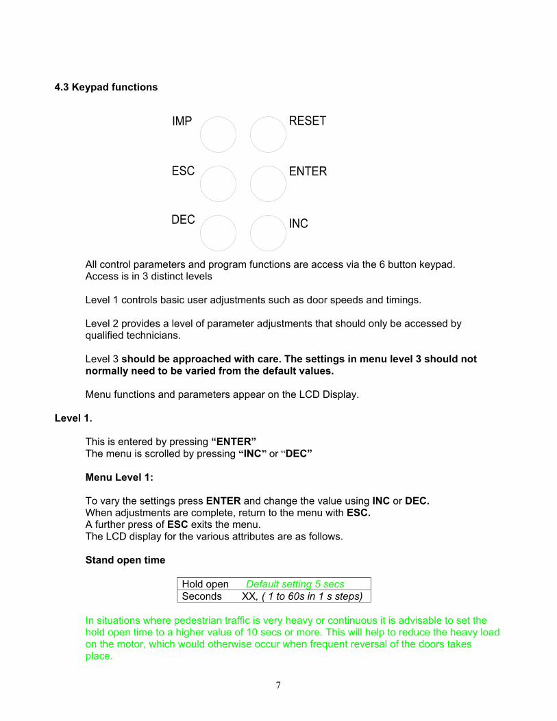
4.3 Keypad functions
All control parameters and program functions are access via the 6 button keypad. Access is in 3 distinct levels Level 1 controls basic user adjustments such as door speeds and timings. Level 2 provides a level of parameter adjustments that should only be accessed by qualified technicians. Level 3 should be approached with care. The settings in menu level 3 should not normally need to be varied from the default values. Menu functions and parameters appear on the LCD Display.
Level 1. This is entered by pressing “ENTER” The menu is scrolled by pressing “INC” or “DEC”
Menu Level 1: To vary the settings press ENTER and change the value using INC or DEC. When adjustments are complete, return to the menu with ESC. A further press of ESC exits the menu. The LCD display for the various attributes are as follows.
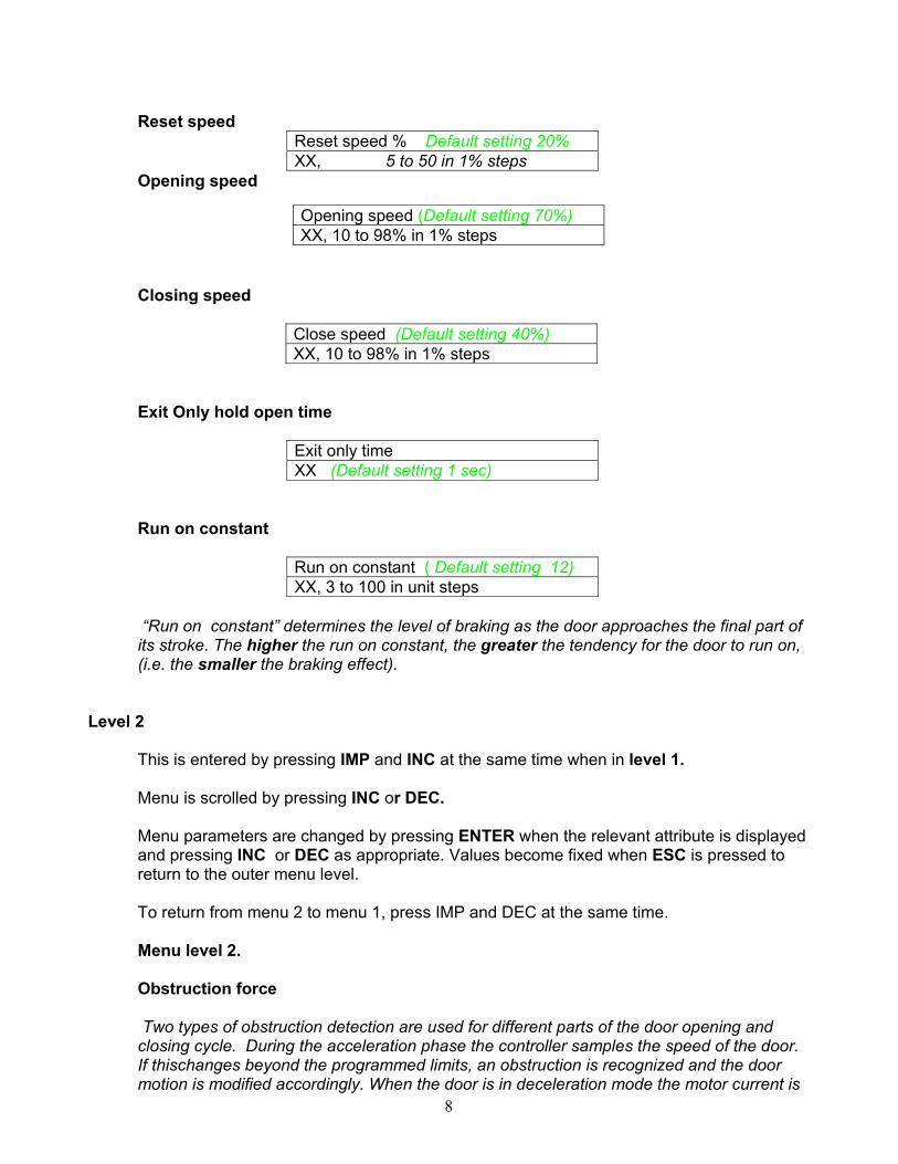
Stand open time
Hold open Default setting 5 secs Seconds XX, ( 1 to 60s in 1 s steps)
In situations where pedestrian traffic is very heavy or continuous it is advisable to set the hold open time to a higher value of 10 secs or more. This will help to reduce the heavy load on the motor, which would otherwise occur when frequent reversal of the doors takes place.
INCDEC
ENTERESC
IMP RESET
8
Reset speed Reset speed % Default setting 20% XX, 5 to 50 in 1% steps
Opening speed
Closing speed
Close speed (Default setting 40%) XX, 10 to 98% in 1% steps
Exit Only hold open time
Exit only time XX (Default setting 1 sec)
Run on constant
Run on constant ( Default setting 12) XX, 3 to 100 in unit steps
“Run on constant” determines the level of braking as the door approaches the final part of its stroke. The higher the run on constant, the greater the tendency for the door to run on, (i.e. the smaller the braking effect).
Level 2 This is entered by pressing IMP and INC at the same time when in level 1. Menu is scrolled by pressing INC or DEC. Menu parameters are changed by pressing ENTER when the relevant attribute is displayed and pressing INC or DEC as appropriate. Values become fixed when ESC is pressed to return to the outer menu level. To return from menu 2 to menu 1, press IMP and DEC at the same time. Menu level 2. Obstruction force Two types of obstruction detection are used for different parts of the door opening and closing cycle. During the acceleration phase the controller samples the speed of the door. If thischanges beyond the programmed limits, an obstruction is recognized and the door motion is modified accordingly. When the door is in deceleration mode the motor current is
Opening speed (Default setting 70%) XX, 10 to 98% in 1% steps
9
sampled and compared with a pre-programmed limit. If between samples this limit is exceeded an obstruction is recognized and the door enters into “obstruction” mode. In the third menu level both current and speed sensitivities can be adjusted independently. These settings then become the basis for the “medium” obstruction level in the second level menu.
XXX displays the datum obstruction level that is set in level 3. This corresponds to the MED level. HIGH an LOW settings are ±4 levels either side of the MED level. The higher the setting the higher the obstruction force required to activate the reversal of the doors. Battery voltage
Battery voltage XX.XV (Displays battery volts)
Supply voltage
Supply voltage XX.XV (Displays supply volts)
Closed offset This displays the encoder positional offset when the doors are closed. With standard set up for a 2M opening bi-parting door, each offset count represents approx 1mm.
Closed offset XX (Default setting 2)
Open offset
Open offset XX (Default setting 10)
Battery monitor
Battery monitor ON / OFF ( Default setting ON)
ON: Battery failure or low voltage causes doors to go the state,(open or closed), that is programmed in level 3. The doors will remain in that state until the battery is restored. OFF: The doors continue to work normally under mains power when battery fails. Digital inputs
Digital inputs
10
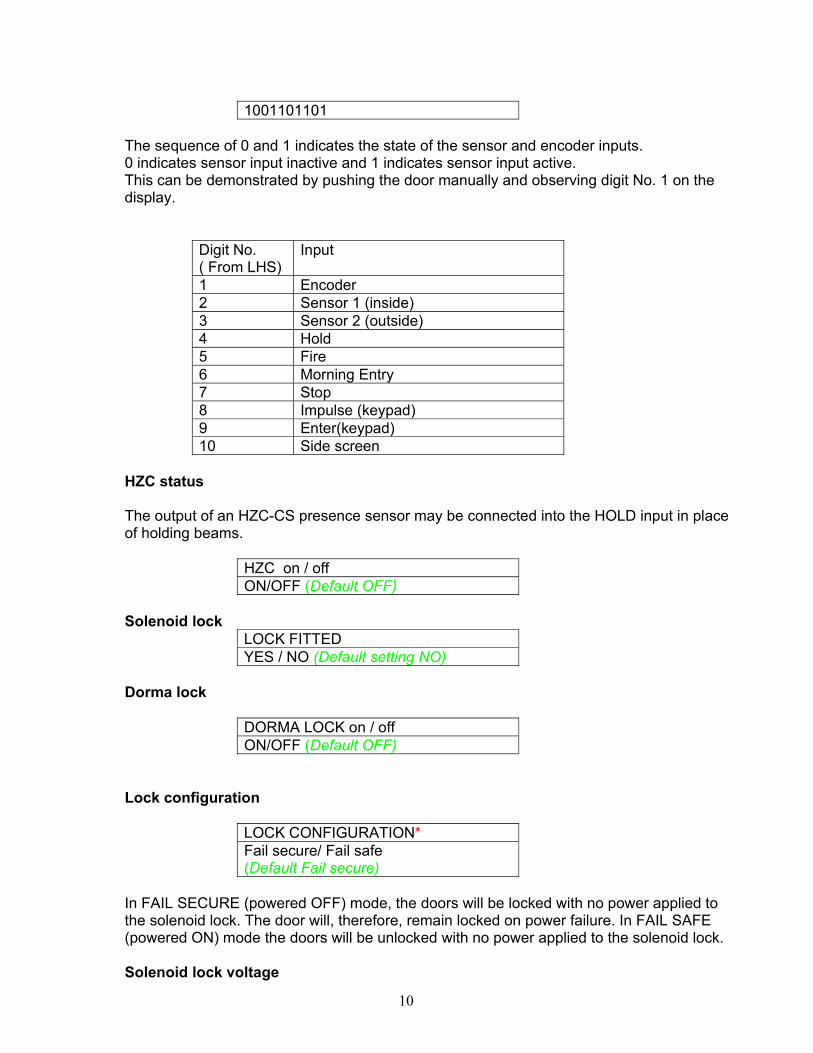
1001101101 The sequence of 0 and 1 indicates the state of the sensor and encoder inputs. 0 indicates sensor input inactive and 1 indicates sensor input active. This can be demonstrated by pushing the door manually and observing digit No. 1 on the display.
Digit No. ( From LHS)
Input
1 Encoder 2 Sensor 1 (inside) 3 Sensor 2 (outside) 4 Hold 5 Fire 6 Morning Entry 7 Stop 8 Impulse (keypad) 9 Enter(keypad) 10 Side screen
HZC status
The output of an HZC-CS presence sensor may be connected into the HOLD input in place of holding beams.
In FAIL SECURE (powered OFF) mode, the doors will be locked with no power applied to the solenoid lock. The door will, therefore, remain locked on power failure. In FAIL SAFE (powered ON) mode the doors will be unlocked with no power applied to the solenoid lock.
Solenoid lock voltage
11
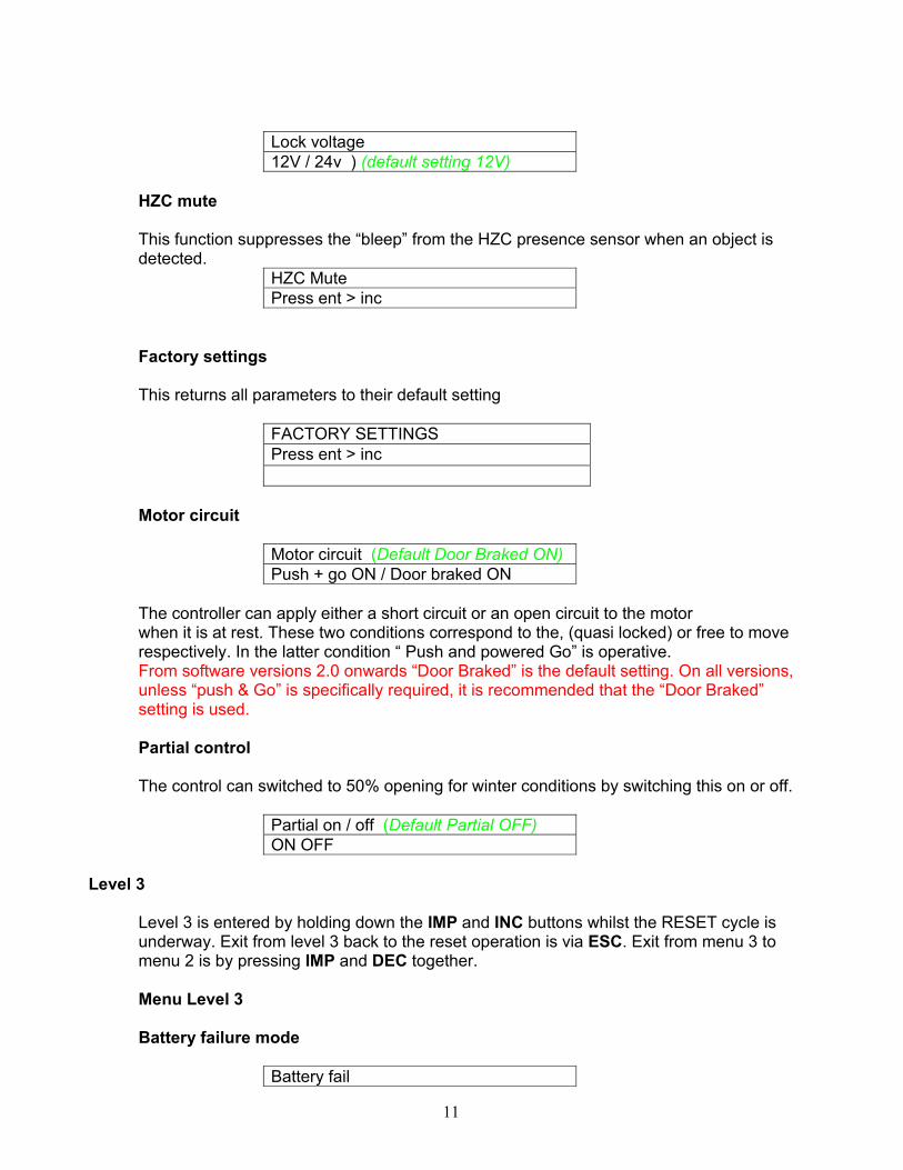
Lock voltage 12V / 24v ) (default setting 12V)
HZC mute
This function suppresses the “bleep” from the HZC presence sensor when an object is detected.
HZC Mute Press ent > inc
Factory settings
This returns all parameters to their default setting
FACTORY SETTINGS Press ent > inc
Motor circuit
Motor circuit (Default Door Braked ON) Push + go ON / Door braked ON
The controller can apply either a short circuit or an open circuit to the motor when it is at rest. These two conditions correspond to the, (quasi locked) or free to move respectively. In the latter condition “ Push and powered Go” is operative. From software versions 2.0 onwards “Door Braked” is the default setting. On all versions, unless “push & Go” is specifically required, it is recommended that the “Door Braked” setting is used.
Partial control The control can switched to 50% opening for winter conditions by switching this on or off.
Partial on / off (Default Partial OFF) ON OFF
Level 3
Level 3 is entered by holding down the IMP and INC buttons whilst the RESET cycle is underway. Exit from level 3 back to the reset operation is via ESC. Exit from menu 3 to menu 2 is by pressing IMP and DEC together. Menu Level 3 Battery failure mode
Battery fail
12
OPEN / CLOSE (Default setting OPEN)
Fire mode
Fire mode OPEN / CLOSE (default setting OPEN)
Deceleration constant
At the end of the fast section of opening or closing the controller decelerates the door at a uniform rate. The DECEL constant varies this rate of deceleration. A high number indicates higher deceleration. Thus if the door tends to under-shoot the DECEL constant should be decreased and if the tendency is for overshoot, the DECEL constant should be increased.
Decel constant XX (Default setting 25)
Obstruction, speed sensitivity
Speed sense XX (default setting 3)
Obstruction, current sensitivity
Current sense XX (default setting 10)
Power failure mode
This determines, in the event of power failure, whether the doors continues to operate on battery power or the doors revert to the pre-programmed failure state, (i.e. OPEN or CLOSED)
Power fail mode CONTIN / PRE-SET (default PRE-SET)
Power failure pre-set condition
Power fail pre-set OPEN / CLOSE (default setting OPEN)
Encoder count divide factor
This calculation is now done automatically at the reset open stage and is not user configurable
13
Encoder divide Factor XX (default setting 6)
Monitoring
This is a monitoring function that shows the last operation of the control, it can be used to fault diagnose, but it needs to be done by consultation with triton controls.
Total Counter This is a total cycle counter and can not be reset by the user. Level 4 (manual mode)
This provides a means of checking the basic door controller and motor functions. It enables the door to be opened or closed at the reset speed by pressing the INC or DEC buttons respectively. Entry to the level 4, manual mode is gained by holding down the INC and DEC buttons whilst the RESET is under way. Press RESET again to exit from level 4, manual mode, and return to the reset operation.
5. SET UP PROCEDURE
5.1 Initial set-up
All connections, apart from the activation sensors, having been made, the system is ready for power up
Manually set doors to half way position.
Switch on. If motor connection is correct, the doors should start to close. If not the control will detect a negative countand reverse the direction
If door starts by closing, allow the RESET to continue The doors will close and after a short pause will commence to open. As the door opens observe LCD display. This should count from 600 upwards.
The doors should now complete the reset cycle. Note: On versions from 1.14 onwards this is accomplished automatically. If the opening phase commences with no upward count, the door will stop and reverse to closed. It will then open again with the correct A/B selection as demonstrated by the upward count.
If the encoder divide factor in menu LEVEL 3 is incorrectly set, the door will halt at the fully open position and the LCD will display “ incorrect counts”.
14
NOTE FROM VERSION 2.3 ONWARDS THIS IS AUTOMATICALLY CALCULATED BY THE PROCESSOR DURING THE RESET PHASE AND NO OPERATOR ADJUSTMENT IS NECCESARY.
5.2 Optimisation of the door motion.
Activate the door by pressing the IMPulse button. With the RUN ON parameter, (LEVEL 1 MENU) correctly set, the door should come smoothly to rest on opening and closing.
In most applications adjustment of RUN ON CONSTANT should be sufficient for smooth operation. It may in a minority of cases also be necessary to adjust the DECEL CONSTANT in menu level 3. This, however, should not normally be necessary.
.
5.3 Obstruction force levels
Check obstruction force levels on door and adjust as necessary.
See section D CONTROL FUNCTIONS, Menu level 2 “OBSTRUCTION SENSITIVITY LEVEL” and Menu level 3, “OBSTRUCTION SENSITIVITY”.