98
OPERATING INSTRUCTIONS GM901-02 CO Measuring Device with Measuring Probe Installation, Operation, Maintenance

O P E R A T I N G I N S T R U C T I O N S
GM901-02CO Measuring Device with Measuring Probe
Installation, Operation, Maintenance

Described product
GM901-02
with measuring probe
Manufacturer
SICK AGErwin-Sick-Str. 179183 WaldkirchGermany
Legal information
This work is protected by copyright. Any rights derived from the copyright shall bereserved for SICK AG. Reproduction of this document or parts of this document is onlypermissible within the limits of the legal determination of Copyright Law. Any modifica‐tion, abridgment or translation of this document is prohibited without the express writ‐ten permission of SICK AG.
The trademarks stated in this document are the property of their respective owner.
© SICK AG. All rights reserved.
Original document
This document is an original document of SICK AG.
2 O P E R A T I N G I N S T R U C T I O N S | GM901-02 8008932/Y153/3-0/2016-03 | SICKSubject to change without notice
Contents
1 About this document........................................................................ 61.1 Function of this document....................................................................... 61.2 Scope of application................................................................................. 61.3 Target group.............................................................................................. 61.4 Symbols and document conventions...................................................... 6
1.4.1 Warning symbols...................................................................... 61.4.2 Warning levels / Signal words................................................. 71.4.3 Information symbols................................................................ 7
2 Safety information............................................................................ 82.1 Basic safety information........................................................................... 82.2 Intended use............................................................................................. 9
2.2.1 Purpose of the device.............................................................. 92.2.2 Responsibility of user.............................................................. 10
3 Product description........................................................................... 113.1 Product identification............................................................................... 113.2 Product features....................................................................................... 113.3 GM901-02 layout...................................................................................... 123.4 Measuring probes..................................................................................... 133.5 Evaluation unit.......................................................................................... 163.6 Accessories .............................................................................................. 16
4 Important information on GPP measuring probes....................... 19
5 Transport and storage....................................................................... 205.1 Transport safeguards............................................................................... 20
6 Mounting............................................................................................. 216.1 Information on installing the sender/receiver unit and measuring
probe......................................................................................................... 216.2 Overview of the installation steps (duct-side preparation).................... 226.3 Scope of delivery...................................................................................... 22
6.3.1 Check scope of delivery.......................................................... 226.3.2 Checking the delivery state..................................................... 22
6.4 Installing the flange with tube................................................................. 236.5 Installing the evaluation unit................................................................... 25
7 Electrical installation........................................................................ 267.1 Safety information for electrical installation........................................... 267.2 Connection overview................................................................................ 27
7.2.1 Connection diagram for standard version............................. 277.2.2 Electrical wiring on the evaluation unit.................................. 287.2.3 Connection diagram with terminal box (detached evalua‐
tion unit)................................................................................... 30
CONTENTS
8008932/Y153/3-0/2016-03 | SICK O P E R A T I N G I N S T R U C T I O N S | GM901-02 3Subject to change without notice

7.3 Uninstalling the electrical system............................................................ 32
8 Commissioning.................................................................................. 338.1 Safety information for commissioning.................................................... 33
8.1.1 Important information on GPP measuring probes................ 358.2 Overview of commissioning work............................................................ 358.3 Material required ..................................................................................... 358.4 Overview of commissioning steps........................................................... 368.5 Criteria for switching on............................................................................ 368.6 Zero adjust................................................................................................ 37
8.6.1 Manual SPAN test (optional)................................................... 378.6.2 Online SPAN test according to EPA Guidelines...................... 398.6.3 Automatic SPAN test................................................................ 41
8.7 Basic parameters set............................................................................... 438.8 Installing the sender and receiver........................................................... 448.9 Connecting the sender and receiver with a CAN line............................. 488.10 Installing the weatherproof cover............................................................ 49
9 Operation............................................................................................ 519.1 Safety......................................................................................................... 519.2 Operating and display elements.............................................................. 51
9.2.1 LEDs.......................................................................................... 519.2.2 Operator panel of the evaluation unit GM901...................... 529.2.3 Setting the display contrast.................................................... 53
9.3 Entering the password.............................................................................. 549.4 Menus........................................................................................................ 55
9.4.1 Measuring mode...................................................................... 559.4.2 Diagnosis.................................................................................. 559.4.3 Parameters (settings).............................................................. 569.4.4 Calibration (Cal)....................................................................... 709.4.5 Service menu "Maint".............................................................. 73
10 Maintenance...................................................................................... 7610.1 Safety......................................................................................................... 7610.2 Preparatory work....................................................................................... 7710.3 Visual inspection....................................................................................... 7710.4 Maintenance plan..................................................................................... 77
10.4.1 Maintenance Table for sender/receiver unit......................... 7810.4.2 Maintenance Table for GPP measuring probe....................... 7810.4.3 Maintenance Table for purge air unit..................................... 7810.4.4 Maintenance Table for GMP measuring probe...................... 7810.4.5 Final maintenance work.......................................................... 78
11 Troubleshooting................................................................................. 7911.1 Warning messages................................................................................... 7911.2 Malfunction messages............................................................................. 80
CONTENTS
4 O P E R A T I N G I N S T R U C T I O N S | GM901-02 8008932/Y153/3-0/2016-03 | SICKSubject to change without notice
11.3 Troubleshooting on the sender................................................................ 8111.4 Troubleshooting on receiver..................................................................... 8211.5 Troubleshooting on the evaluation unit................................................... 8311.6 Communication fault between evaluation unit and receiver................. 84
11.6.1 Sensor values for trouble-free operation............................... 8411.6.2 Remote Diagnosis, GM901 Sensor Values............................ 85
11.7 Measures after purge air failure (when using the GMP measuringprobe)........................................................................................................ 86
12 Decommissioning............................................................................. 8712.1 Safety information on shutting down...................................................... 8712.2 Materials and tools required.................................................................... 8812.3 Disassembling the sender and receiver.................................................. 8812.4 Storage...................................................................................................... 8912.5 Disposal..................................................................................................... 89
13 Technical data.................................................................................... 9013.1 Technical data........................................................................................... 90
13.1.1 Operating data......................................................................... 9013.1.2 Technical Data - Measuring Probes........................................ 91
13.2 Dimension drawings................................................................................. 9213.2.1 Dimension drawing, sender/receiver unit with GMP meas‐
uring probe............................................................................... 9213.2.2 Dimension drawing, sender/receiver unit with GPP meas‐
uring probe............................................................................... 9213.2.3 Dimension drawing, evaluation unit....................................... 9313.2.4 Dimension drawings, accessories.......................................... 94
14 Ordering information........................................................................ 9614.1 Spare parts............................................................................................... 9614.2 Accessories............................................................................................... 96
15 List of tables....................................................................................... 97
CONTENTS
8008932/Y153/3-0/2016-03 | SICK O P E R A T I N G I N S T R U C T I O N S | GM901-02 5Subject to change without notice

1 About this document
1.1 Function of this document
These Operating Instructions describe:
• System components• Start-up• Operation• Maintenance work required for reliable operation• Troubleshooting
1.2 Scope of application
These Operating Instructions are valid only for the gas in-situ measuring device with thedesignation GM901 with measuring probe.
They are not valid for the other gas in-situ measuring devices from SICK.
1.3 Target group
This Manual is intended for persons installing, operating and maintaining the device.
Operation
The device should only be operated by skilled technicians who, based on their technicaltraining and knowledge as well as knowledge of the relevant regulations, can assessthe tasks given and recognize the hazards involved.
Installation and maintenance
Skilled technicians may be required at certain times during installation and mainte‐nance.
Please observe the information at the beginning of the respective Sections.
1.4 Symbols and document conventions
1.4.1 Warning symbols
Symbol Significance
Immediate hazard of severe personal injury or death
Hazard (general)
Hazard through electrical voltage
Hauard through toxic substances
Hazard for the environment/nature/organic life
Table 1: Warning symbols
1 ABOUT THIS DOCUMENT
6 O P E R A T I N G I N S T R U C T I O N S | GM901-02 8008932/Y153/3-0/2016-03 | SICKSubject to change without notice
1.4.2 Warning levels / Signal words
DANGER
Risk or hazardous situation which will result in severe personal injury or death.
WARNING
Risk or hazardous situation which could result in severe personal injury or death.
CAUTION
Hazard or unsafe practice which could result in less severe or minor injuries.
Notice
Hazard which could result in property damage.
Note
Hints
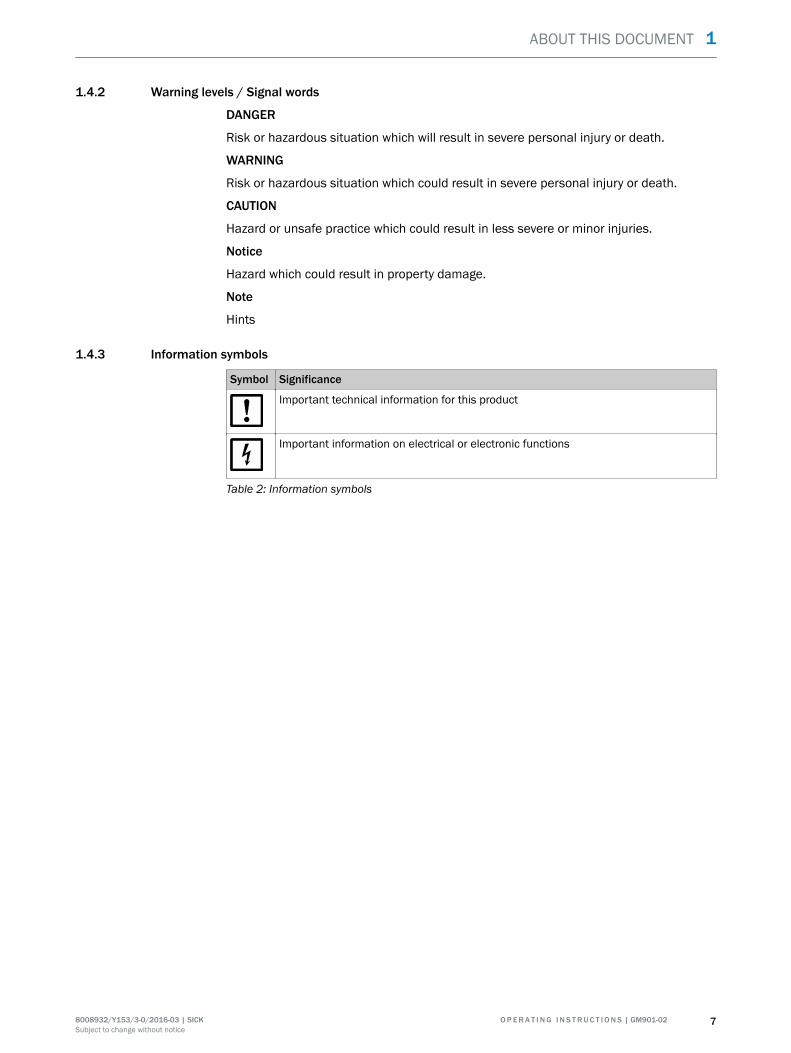
1.4.3 Information symbols
Symbol Significance
Important technical information for this product
Important information on electrical or electronic functions
Table 2: Information symbols
ABOUT THIS DOCUMENT 1
8008932/Y153/3-0/2016-03 | SICK O P E R A T I N G I N S T R U C T I O N S | GM901-02 7Subject to change without notice

2 Safety information
2.1 Basic safety information
ATTENTIONResponsibility of the operator in case of device malfunctions or failureIf the GM901-02 is used as a sensor in combination with control technology, the opera‐tor must ensure that a failure or malfunction on the GM901-02 cannot lead to unal‐lowed damage or hazardous operating states.
ATTENTIONResponsibility for system safetyThe person setting the system up is responsible for the safety of the system in whichthe device is integrated.
ATTENTIONResponsibility of the operator for correct usage of the deviceBasis of this Manual is the delivery of the device according to the preceding projectplanning (e.g., based on the SICK application questionnaire) and the relevant deliverystate of the device (see delivered system documentation).
b Contact SICK Customer Service if you are not sure whether the device correspondsto the state defined during project planning or to the delivered system documenta‐tion.
DANGERHealth risk when safety information is not availableImproper installation or maintenance work can lead to accidents with serious conse‐quences for the health of persons carrying out these tasks.
b Keep these Operating Instructions and the associated instructions available forreference.
b Read and observe these Operating Instructions.b Observe all safety instructions.b If anything is not clear: Please contact SICK Customer Service.b Use the device only as described in "Intended use". The manufacturer bears no
responsibility for any other use.b Carry out the specified maintenance work.b Do not attempt any work on or repairs to the device unless described in this Man‐
ual. Do not remove, add or change any components in or on the device unlesssuch changes are officially allowed and specified by the manufacturer. Failure toobserve these precautions could result in:– Voiding the manufacturer's warranty.– The device becoming dangerous.
b Observe all relevant regulations concerning protective clothing.
2 SAFETY INFORMATION
8 O P E R A T I N G I N S T R U C T I O N S | GM901-02 8008932/Y153/3-0/2016-03 | SICKSubject to change without notice
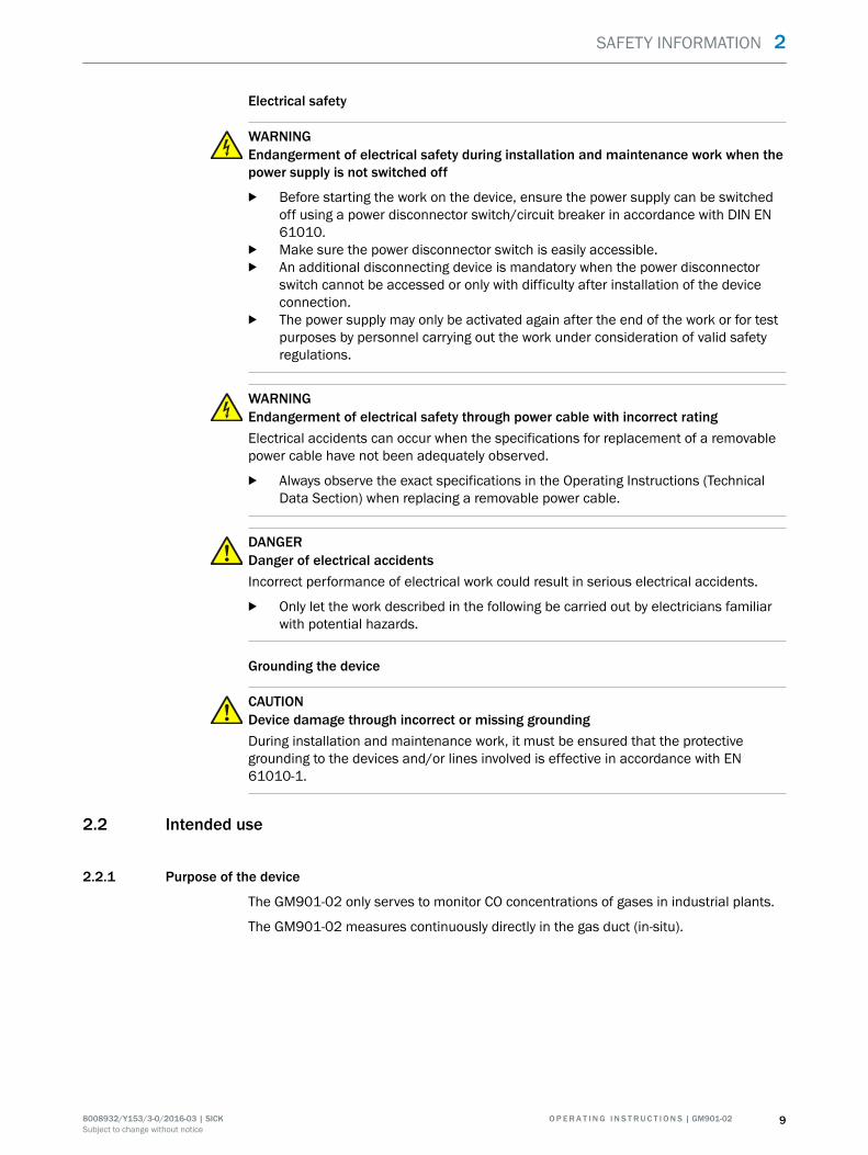
Electrical safety
WARNINGEndangerment of electrical safety during installation and maintenance work when thepower supply is not switched off
b Before starting the work on the device, ensure the power supply can be switchedoff using a power disconnector switch/circuit breaker in accordance with DIN EN61010.
b Make sure the power disconnector switch is easily accessible.b An additional disconnecting device is mandatory when the power disconnector
switch cannot be accessed or only with difficulty after installation of the deviceconnection.
b The power supply may only be activated again after the end of the work or for testpurposes by personnel carrying out the work under consideration of valid safetyregulations.
WARNINGEndangerment of electrical safety through power cable with incorrect ratingElectrical accidents can occur when the specifications for replacement of a removablepower cable have not been adequately observed.
b Always observe the exact specifications in the Operating Instructions (TechnicalData Section) when replacing a removable power cable.
DANGERDanger of electrical accidentsIncorrect performance of electrical work could result in serious electrical accidents.
b Only let the work described in the following be carried out by electricians familiarwith potential hazards.
Grounding the device
CAUTIONDevice damage through incorrect or missing groundingDuring installation and maintenance work, it must be ensured that the protectivegrounding to the devices and/or lines involved is effective in accordance with EN61010-1.
2.2 Intended use
2.2.1 Purpose of the device
The GM901-02 only serves to monitor CO concentrations of gases in industrial plants.
The GM901-02 measures continuously directly in the gas duct (in-situ).
SAFETY INFORMATION 2
8008932/Y153/3-0/2016-03 | SICK O P E R A T I N G I N S T R U C T I O N S | GM901-02 9Subject to change without notice
2.2.2 Responsibility of user
Designated users
see "Target group", page 6.
Correct project planning
• Basis of this Manual is the delivery of the device according to the precedingproject planning (e.g., based on the SICK application questionnaire) and the rele‐vant delivery state of the device (see delivered system documentation).w Contact SICK Customer Service if you are not sure whether the device corre‐
sponds to the state defined during project planning or to the delivered systemdocumentation.
Correct use
b Use the device only as described in "Intended use".The manufacturer bears no responsibility for any other use.
b Carry out the specified maintenance work.b Do not attempt any work on or repairs to the device unless described in this Man‐
ual.Do not remove, add or change any components in or on the device unless suchchanges are officially allowed and specified by the manufacturer.Failure to observe these precautions could result in:
° Voiding the manufacturer's warranty.
° The device becoming dangerous.
Special local requirements
In addition to the information in these Operating Instructions, follow all local laws, tech‐nical rules and company-internal operating directives applicable wherever the device isinstalled.
Read the Operating Instructions
b Read and observe these Operating Instructions.b Observe all safety instructions.b If anything is not clear: Please contact SICK Customer Service.
Retain documents
These Operating Instructions must be
b Available for reference.b Passed on to new owners.
2 SAFETY INFORMATION
10 O P E R A T I N G I N S T R U C T I O N S | GM901-02 8008932/Y153/3-0/2016-03 | SICKSubject to change without notice

3 Product description
3.1 Product identification
Product name GM901-02
Device version CO measuring device with probe
Manufacturer SICK AG Erwin-Sick-Str. 1 • D-79183 Waldkirch • Germany
Type plates • Sender and receiver: Under the optics tube
• Measuring probe: On the electronics housing
Table 3: Product identification
3.2 Product features
• The in-situ gas analyzer GM901-02 serves for continuous measurement of gasconcentrations in industrial plants.
• The GM901-02 is an in-situ measuring system which means measuring is donedirectly in the gas carrying duct.
• Measuring components: CO and reference value temperature.• Measuring principle: Infrared spectroscopic gas filter correlation.
PRODUCT DESCRIPTION 3
8008932/Y153/3-0/2016-03 | SICK O P E R A T I N G I N S T R U C T I O N S | GM901-02 11Subject to change without notice

3.3 GM901-02 layout
Enter meas
diag par cal maint
OperationServiceWarningMalfunction
GM 901Evaluation Unit
1
2
3
4
5
6
á
8
9
7
ß à
â ã ä
å
Figure 1: Device component overview
System components Line
1 GM901-02 sender 9 CAN connection, sender-receiver
2 GM901-02 receiver ß Signal line, GM901 receiver to connection unit
3 T-piece with beam splitter à Power supply 115 V/230 V AC
4 Measuring probe á Line to temperature sensor PT1000
5 Temperature sensor PT1000 â Power supply 115 V/230 V AC
6 Connection unit (optional) for distance analyzer - EvU >20 m
ã Signal cable, max. 1000 m (CAN bus and temperature)
7 Evaluation unit ä • Analog output signals: 1 input, 1 output
• Status signals: 1 input, 3 outputs
8 Service PC å RS232 interface (Service)
Table 4: GM901-02 layout
NOTEIf the evaluation unit is installed detached, the 20 mA converter must be installed near the device.
3 PRODUCT DESCRIPTION
12 O P E R A T I N G I N S T R U C T I O N S | GM901-02 8008932/Y153/3-0/2016-03 | SICKSubject to change without notice

3.4 Measuring probes
■ Gas diffusion probe (GPP)
Figure 2: GPP measuring probe with ceramic filter
Characteristics:
• Suitable for applications with dry process gas• Measuring probe material:
– Standard: Stainless steel (1.4571/316 Ti)– On request: 1.4539
• No moving parts• Active elements: Heaters of the optical surfaces and their controls• Temperature sensor PT1000• Power supply via a plug• Filter element for filtering dust particles
° With ceramic filter: Dust removal for particles > 1 μm• EPA compliant (EPA Guideline CFR 40, Part 60 or Part 75): The measuring cham‐
ber can be filled with known concentrations of test gases• SPAN and zero point test possible: Usage as "zero path" by purging the measuring
chamber with air or N2 possible• Pressure-resistant up to 200 mbar differential pressure to duct• No special flow conditions in duct necessary
PRODUCT DESCRIPTION 3
8008932/Y153/3-0/2016-03 | SICK O P E R A T I N G I N S T R U C T I O N S | GM901-02 13Subject to change without notice

■ GMP measuring probe - probe with open measuring gap
Figure 3: GMP measuring probe with open measuring gap and PT1000 tem‐perature sensor
Characteristics:
• Very short response times• High temperature stability• Continuous purge air necessary• Air outlet in the duct 90° to gas flow• Temperature sensor PT 1000 for continuous measurement of medium tempera‐
tures in the active measuring path of the probe
Gas inlet and outlet with the GMP measuring probe
The GMP probe has a closing device towards the opening for sample gas and is oper‐ated using the lever on the probe flange. This ensures a correct purge air function with‐out an analyzer.
1
2
34
Figure 4: GMP measuring probe closing device
1 Purge air outlet2 Open measuring path (measuring gap)3 Closing device lever4 Closing device set to position "open"
3 PRODUCT DESCRIPTION
14 O P E R A T I N G I N S T R U C T I O N S | GM901-02 8008932/Y153/3-0/2016-03 | SICKSubject to change without notice

GM901-02 with GMP probe and purge air unit
1
2
3
4
6
5
7
Figure 5: GMP measuring probe with purge air unit on the duct
1 GM901-02 sender2 GM901-02 receiver3 T-piece with beam splitter4 Lever for closing device of the sample gas opening5 GMP measuring probe6 Purge air hose7 Purge air unit SLV4
Measuring probes in comparison
Measuring probe feature GMP (open probe) GPP (dry)
Type Measuring path open in flowdirection; purge air guidancewith outlet aligned 90° to gasflow
Gas diffusion probe withceramic filter, for dry samplegas
Max. gas temperature 430 °C 430 °C
Gas check according to EPAspecification possible
- Yes
Purge air supply required Yes No
Heating on optical interfacesin the probe
- Yes, with integrated control
Flow rate of sample gas 1 ... 40 m/s < 40 m/s
Suitable for wet sample gas Yes No
Maximum duct pressure ±120 hPa, depending onpurge air supply
±200 hPa with safety clampson the device flange seal
Measurable components CO
System response time (T90) ≥ 5 s ≥ 120 s
Duct diameter > 360 mm > 300 mm
Table 5: GMP and GPP measuring probes in comparison
PRODUCT DESCRIPTION 3
8008932/Y153/3-0/2016-03 | SICK O P E R A T I N G I N S T R U C T I O N S | GM901-02 15Subject to change without notice
Measuring probe feature GMP (open probe) GPP (dry)
Dust concentration < 2 g/m3 a.c. < 30 g/m3 a.c.
Probe lengths available [m] 1.1 1.1
Active measuring paths availa‐ble [mm]
250/500
Table 5: GMP and GPP measuring probes in comparison
3.5 Evaluation unit
■ Evaluation unit with connection line (4 m)
The evaluation unit (EvU) serves in the measuring system as user interface and pre‐pares and outputs the measured values and performs control and monitoring func‐tions. The EvU can be located in the vicinity of the sender/receiver unit. It can also belocated up to about 1000 meters from the sampling point, e.g. installed in the switchcenter or monitoring center, and performs the following functions:
• Output of measured values, computed data and operating states• Communication with the peripheral equipment• Output of error messages and other status signals• Access during service (diagnosis)
3.6 Accessories
■ Connection unit
– For CAN bus with 24 V power supply– To extend the distances 19 ... 1000 m between analyzer and evaluation unit
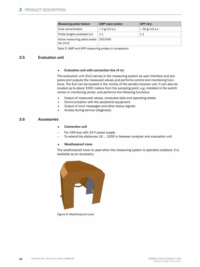
■ Weatherproof cover
The weatherproof cover is used when the measuring system is operated outdoors. It isavailable as an accessory.
Figure 6: Weatherproof cover
3 PRODUCT DESCRIPTION
16 O P E R A T I N G I N S T R U C T I O N S | GM901-02 8008932/Y153/3-0/2016-03 | SICKSubject to change without notice

■ Purge air unit
1
6
54
3
2
Figure 7: Purge air unit components
1 Low-pressure monitor2 Air filter3 Quick-release clamps4 Purge air blower5 Purge air hose6 Hose clamps
The purge air unit serves to feed purge air when using the open measuring probe(GMP). It supplies filtered ambient air to the purge air fixture and protects the opticalsurfaces of the sender and the receiver against contamination.
DANGERFurther information on the purge air unit, see Operating Instructions of the purge airunit.
■ Optical adjustment deviceTo align the sender and receiver
PRODUCT DESCRIPTION 3
8008932/Y153/3-0/2016-03 | SICK O P E R A T I N G I N S T R U C T I O N S | GM901-02 17Subject to change without notice

Figure 8: Optical adjustment device
■ CO test cells with holder (SPAN test)
For the yearly drift control (zero point and sensitivity)
Figure 9: CO test cell with holder in transport case
Deliverable test cells
Test cells are available depending on the application-specific measuring ranges, meas‐uring paths and test points (e.g. 70%).
3 PRODUCT DESCRIPTION
18 O P E R A T I N G I N S T R U C T I O N S | GM901-02 8008932/Y153/3-0/2016-03 | SICKSubject to change without notice

4 Important information on GPP measuring probes
CAUTIONObserve the following information during commissioning of the GPP measuring probeto avoid damage to the measuring system and to achieve stable measurements.
• Check the filter surface visually for damage.• Warm the probe up for about 30 minutes beforehand so that the temperature of
the window and triple reflector is sufficient to prevent condensation on the opticalsurfaces.
• Gas can escape at the measuring probe during overpressure processes when the1/4" plug is open or loose. Air is suctioned into the measuring probe during low-pressure processes. The measured value in the chamber then drops depending onthe low-pressure in the process, possibly down to zero.
• Do not damage the filter when inserting the probe in the flange.
IMPORTANT INFORMATION ON GPP MEASURING PROBES 4
8008932/Y153/3-0/2016-03 | SICK O P E R A T I N G I N S T R U C T I O N S | GM901-02 19Subject to change without notice

5 Transport and storage
5.1 Transport safeguards
Check the transport safeguards
b Check all transport safeguards for damage.
Remove the transport safeguards from the measuring probe (GMP)
Figure 10: Transport safeguards on the GMP probe
1 Protective stickers2 Protective caps
1 Remove the protective stickers.2 Remove the caps.
5 TRANSPORT AND STORAGE
20 O P E R A T I N G I N S T R U C T I O N S | GM901-02 8008932/Y153/3-0/2016-03 | SICKSubject to change without notice

6 Mounting
6.1 Information on installing the sender/receiver unit and measuring probe
Information
CAUTIONDamage to device and plant through unsecured parts during installationDuring installation, parts of the device or flange can fall into the duct and cause dam‐age.
b Secure all parts with wire.
NOTEThe sender, receiver and measuring probe are first installed on the duct during commis‐sioning because these require an initial adjustment away from the gas-carrying duct. Toavoid problems during commissioning, the SR-unit and measuring probe must bestored in a dry place free from dust, preferably at room temperature, until commission‐ing.
DANGERHealth risk though pressure and hot or toxic gasesDangerous pressures, hot or toxic gases can escape when opening the duct dependingon the process gas characteristics.
b Before installing the sender, receiver and measuring probe, be sure to take allsafety measures that prevent gas escaping uncontrolled.
ATTENTIONDamage to the sender, receiver and measuring probe when fitted too early on themeasuring ductUnfavorable ambient conditions or atmosphere in the measuring duct can damage themeasuring system which prevents commissioning.
b First fit the sender/receiver unit and measuring probe during commissioning.b Before fitting, check the process and ambient conditions according to the Techni‐
cal Data are ensured.
MOUNTING 6
8008932/Y153/3-0/2016-03 | SICK O P E R A T I N G I N S T R U C T I O N S | GM901-02 21Subject to change without notice

6.2 Overview of the installation steps (duct-side preparation)
Step Procedure Reference
1 Install the flange with tube. see "Installing the flange with tube",page 23.
2 Install the connection unit (for larger distan‐ces, up to 1000 m, between sampling pointand EvU).
see "Dimension drawing, terminal box",page 95.
6 Install the evaluation unit. see "Installing the evaluation unit",page 25.
Table 6: Installation steps overview
6.3 Scope of delivery
6.3.1 Check scope of delivery
NOTICEThe data of the final inspection protocol must match the data of the order confirmation.
b Check the scope of delivery against the order confirmation and/or delivery note.
Standard scope of delivery
■ Sender/receiver unit:– Sender– Receiver– T-piece
■ Evaluation unit with connection cable■ Connection cable from sender to receiver■ Measuring probe:
– GMP: Gas measuring probe with open measuring gap– GPP: Gas permeation probe
Optional accessories
• Connection unit: For distances up to 1000 m between sender/receiver unit andevaluation unit
• Purge air unit: To protect the optical surfaces of the sender/receiver unit• Weatherproof cover for installation outdoors• Optical adjustment device• CO test cell with holder (SPAN test)• Welding neck flange
6.3.2 Checking the delivery state
NOTICEb Check all components have no exterior damage.b Ensure the supply voltages specified on the type plate match the plant conditions.
6 MOUNTING
22 O P E R A T I N G I N S T R U C T I O N S | GM901-02 8008932/Y153/3-0/2016-03 | SICKSubject to change without notice

6.4 Installing the flange with tube
WARNINGRisk of injury through improper assembly workAll assembly work must be carried out only by competent persons who, based on theirtraining and knowledge as well as knowledge of the relevant regulations, can assessthe tasks given and recognize the hazards involved.
ATTENTIONRisk of temperatures exceeding the limit value through external heat radiationThe ambient temperature must not exceed 55 °C. Heat radiation can cause the sur‐face temperature to be higher than the measured air temperature.
b Strengthen the insulation.
ATTENTIONHazard through overpressure in the systemOverpressure in the duct can lead to leaks at the flange.
b Always observe the limit values for gas pressure.
Available flanges with tube:
• Standard delivery: 1 x flange with tube; 240 mm total length and 125 mm innerdiameter.
• Custom-made versions available on request.• On-site ANSI flange.
Figure 11: Mounting flange
NOTEReinforcement with junction plates recommendedThe device has a relatively high weight.
b Weld junction plates on on-site for reinforcement of ducts with thin walls or at fit‐ting locations subject to vibrations.
MOUNTING 6
8008932/Y153/3-0/2016-03 | SICK O P E R A T I N G I N S T R U C T I O N S | GM901-02 23Subject to change without notice

xxxx
1
2
2
Figure 12: Flange tube with junction plates
1 Marking for assembly position2 On-site junction plates3 The rear side of the threaded bolts serves to fas‐
ten the optional weatherproof cover
Installing the flange with tube
1 Remove an area of 1000 mm x 800 mm of the insulation from the duct.2 Mark the flange center point exactly on the duct wall.
– On ducts made of stone/concrete: Duct opening approx. 2 cm larger than theflange tube outer diameter ; at the same time, plan a light downward inclineof the flange tube by approx. 1° to prevent condensate collecting laterbetween the tube and probe.
– Provide a suitable retainer plate.3 Cut an opening matching the flange tube outer diameter (standard Ø = 133 mm)
in the duct wall and/or retainer plate.4 Insert the flange tube so that the marking points exactly upwards (↑). Tilt the tube
in the duct or on the retainer plate slightly downwards (approx. 1°).5 Affix in the fitting position.
– Weld on junction plates as reinforcement when possible. For ducts made ofstone/concrete: Anchor the retainer plate with flange with tube welded onsecurely to the duct.
6 Weld the flange tube on.
6 MOUNTING
24 O P E R A T I N G I N S T R U C T I O N S | GM901-02 8008932/Y153/3-0/2016-03 | SICKSubject to change without notice

6.5 Installing the evaluation unit
Prerequisite:
• Installation location already determined during project planning.• The maximum line length of 1000 m for all CAN bus connections has been consid‐
ered.
NOTERecommendation: The shorter the distance between sampling point and evaluationunit, the easier it is to use the system.
Prepare the installation location
1 Dimension drawing, see "Dimension drawing, evaluation unit", page 93.2 Based on the dimension drawing of the evaluation unit, make sure sufficient
space is available at the planned installation location to fit and wire the unit aswell as to pivot the housing door.
3 Bore the four holes (Ø 7.2 mm for M8) according to the dimension drawing.
Install the evaluation unit
1 Open the housing cover with a control cabinet key and swivel open.2 Attach the evaluation unit at the installation location using the four planned
mounting holes with suitable screws (M8 x 20).3 Close and lock the housing cover again.
MOUNTING 6
8008932/Y153/3-0/2016-03 | SICK O P E R A T I N G I N S T R U C T I O N S | GM901-02 25Subject to change without notice
7 Electrical installation
7.1 Safety information for electrical installation
WARNINGEndangerment of electrical safety during installation and maintenance work when thepower supply is not switched off
b Before starting the work on the device, ensure the power supply can be switchedoff using a power disconnector switch/circuit breaker in accordance with DIN EN61010.
b Make sure the power disconnector switch is easily accessible.b An additional disconnecting device is mandatory when the power disconnector
switch cannot be accessed or only with difficulty after installation of the deviceconnection.
b The power supply may only be activated again after the end of the work or for testpurposes by personnel carrying out the work under consideration of valid safetyregulations.
WARNINGEndangerment of electrical safety through power cable with incorrect ratingElectrical accidents can occur when the specifications for replacement of a removablepower cable have not been adequately observed.
b Always observe the exact specifications in the Operating Instructions (TechnicalData Section) when replacing a removable power cable.
DANGERDanger of electrical accidentsIncorrect performance of electrical work could result in serious electrical accidents.
b Only let the work described in the following be carried out by electricians familiarwith potential hazards.
CAUTIONDevice damage through incorrect or missing groundingIt must be ensured during installation and maintenance work that the protectivegrounding of the device or lines involved is established in accordance with EN 61010-1.
WARNINGEndangerment of electrical safety through heat damage to linesWhen planning the lines, take into account that the junction box can reach a tempera‐ture >60°C due to self-heating at maximum ambient temperature.
b Only use lines specified for temperatures >80°C.
CAUTIONDevice damage through short circuit on the deviceThe internal electronics can be damaged when signal connections are established andthe power supply is switched on. This is also valid for plug connections.
b Disconnect the analyzer and all connected devices from the power supply (switchoff).
7 ELECTRICAL INSTALLATION
26 O P E R A T I N G I N S T R U C T I O N S | GM901-02 8008932/Y153/3-0/2016-03 | SICKSubject to change without notice
CAUTIONHazard of severe damage to electronic subassemblies through electrostatic discharge(ESD)When touching electronic subassemblies, there is a hazard of severe damage to thesubassembly by electric potential equalization.
b Make sure you have the same electric potential as the subassembly (e.g. bygrounding) before touching the subassembly.
7.2 Connection overview
7.2.1 Connection diagram for standard version
Enter meas
diag par cal maint
OperationServiceWarningMalfunction
GM 901Evaluation Unit
1
2 3 4
5
6
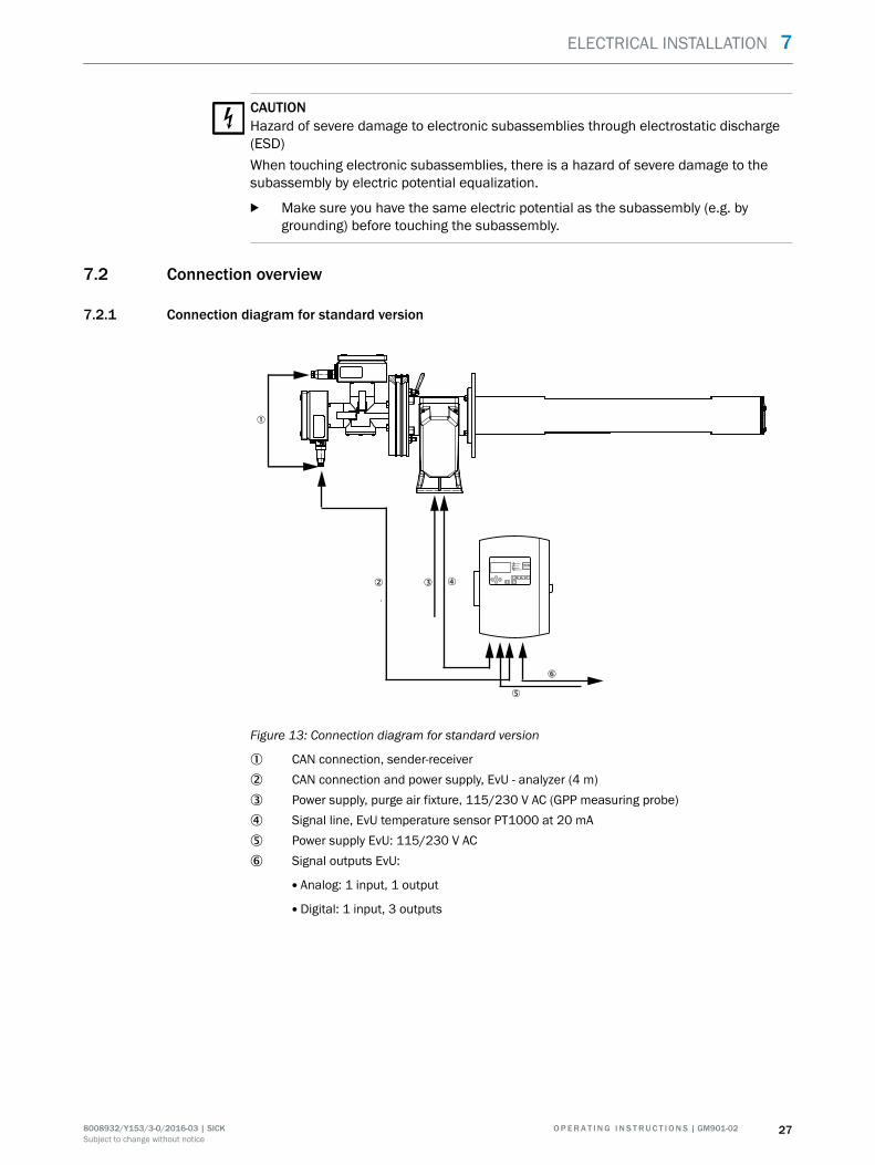
Figure 13: Connection diagram for standard version
1 CAN connection, sender-receiver2 CAN connection and power supply, EvU - analyzer (4 m)3 Power supply, purge air fixture, 115/230 V AC (GPP measuring probe)4 Signal line, EvU temperature sensor PT1000 at 20 mA5 Power supply EvU: 115/230 V AC6 Signal outputs EvU:
Analog: 1 input, 1 output
Digital: 1 input, 3 outputs
ELECTRICAL INSTALLATION 7
8008932/Y153/3-0/2016-03 | SICK O P E R A T I N G I N S T R U C T I O N S | GM901-02 27Subject to change without notice

7.2.2 Electrical wiring on the evaluation unit
Sensor Te
V
-- -- -- TestTest--++++
Digital inDigital in
ContrastContrast
230V230Voror
115V115V
Ser
vice
Ser
vice
++ --
Analog outAnalog outDigital outDigital out
Analog inAnalog in
++
0.. 20mA0.. 20mA100100
0.. 20mA0.. 20mAAC/DC 48VAC/DC 48V30VA 1A30VA 1A40..60Hz40..60Hz
FuseFuse2,5AT 250V2,5AT 250V
PE N L1PE N L1
RS
232
RS
232
DataDatavalidvalid
LimitLimitTestTest
ServiceService
Power CANPower CAN+24V+24V+ - H L GND+ - H L GND
Power +24VPower +24V
SensorSensor
++
1
2
3
4 5
6
Figure 14: Electrical wiring of the evaluation unit
1 Cable bridge: Selection of operating voltage: 115 V or 230 V2 Power supply: 115 V / 230 V3 Potential equalization connection4 Screw cap for power supply cable5 Measuring transducer for PT1000 -> 20mA6 Terminals for wiring by customer
7 ELECTRICAL INSTALLATION
28 O P E R A T I N G I N S T R U C T I O N S | GM901-02 8008932/Y153/3-0/2016-03 | SICKSubject to change without notice
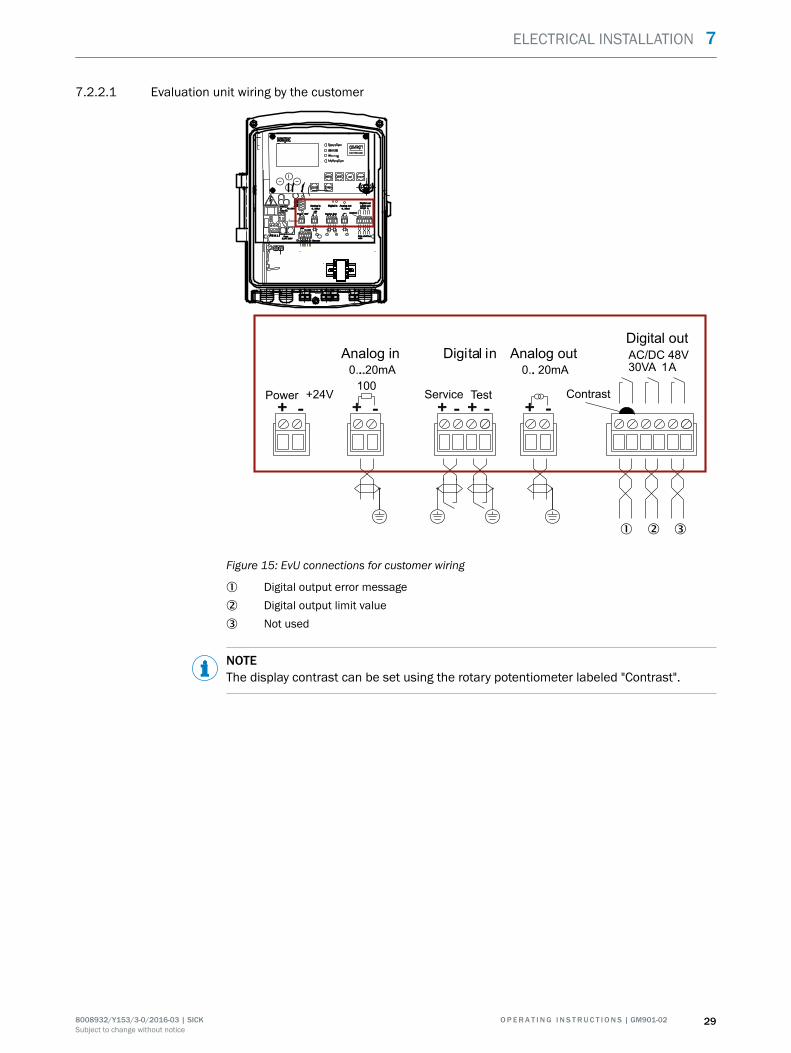
7.2.2.1 Evaluation unit wiring by the customer
Sensor Te
V
-- -- -- TestTest--++++
Digitali nDigital in
ContrastContrast
230V230Voror
115V115V
Ser
vice
Ser
vice
++ --
Analog outAnalog outDigital outDigital out
Analog inAnalog in
++
0.. 20mA0.. 20mA100100
0.. 20mA0.. 20mAAC/DC 48VAC/DC 48V30VA1 A30VA1 A40..60Hz40..60Hz
FuseFuse2,5AT 250V2,5AT 250V
PENL 1PE N L1
RS
232
RS
232
DataDatavalidvalid
LimitLimitTestTest
ServiceService
Power CANPower CAN+24V+24V+- HL GND+ - H L GND
Power +24VPower +24V
SensorSensor
++
-- -- --Test
--++++
Digital in
Contrast
++ --
Analog outDigital out
Analog in++
0.. 20mA..100
0.. 20mA.AC/DC 48V30VA 1A
ServicePower +24V
++
1 2 3
Figure 15: EvU connections for customer wiring
1 Digital output error message2 Digital output limit value3 Not used
NOTEThe display contrast can be set using the rotary potentiometer labeled "Contrast".
ELECTRICAL INSTALLATION 7
8008932/Y153/3-0/2016-03 | SICK O P E R A T I N G I N S T R U C T I O N S | GM901-02 29Subject to change without notice

7.2.3 Connection diagram with terminal box (detached evaluation unit)
Enter meas
diag par cal maint
OperationServiceWarningMalfunction
GM 901Evaluation Unit
1
2 3 4
5
687 6
6
Figure 16: Wiring with terminal box and detached evaluation unit
Lines1 CAN connection, sender-receiver2 CAN connection to connection unit and 24 V supply for sender and receiver3 Purge air fixture power supply (only when using a GPP probe): 115 V / 230 V AC4 Signal line, temperature sensor PT1000 on 20 mA converter -> EvU5 Hose for purge air supply (only when using a GMP probe)6 Power supply 115 V / 230 V AC7 CAN bus between terminal box and evaluation unit, up to max. 1000 m
8 Analog: 1 input, 1 output
Digital: 1 input, 3 outputs
7 ELECTRICAL INSTALLATION
30 O P E R A T I N G I N S T R U C T I O N S | GM901-02 8008932/Y153/3-0/2016-03 | SICKSubject to change without notice
7.2.3.1 Terminal box customer wiring
Fuse 2.5 AT
230/115 V AC40 … 60 Hz
1
250 V
2
321
PE N L1
6
3
5 4
PG 13.5PG 13.5
CAN
-L
+24
GN
DCA
N-H
CAN
GN
DN
C
54321 6
CAN
-LCA
N-H
CAN
GN
D
321
CAN
-L
+24
GN
DCA
N-H
CAN
GN
D
54321
NC
6
CANTerminator
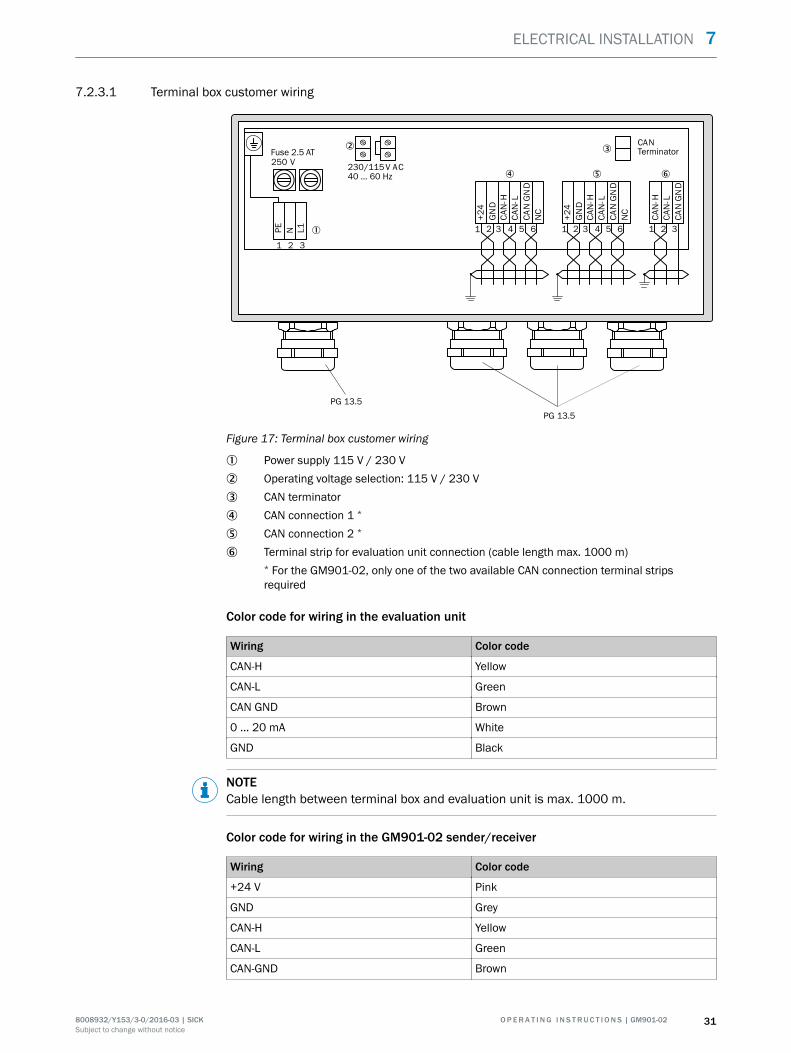
Figure 17: Terminal box customer wiring
1 Power supply 115 V / 230 V2 Operating voltage selection: 115 V / 230 V3 CAN terminator4 CAN connection 1 *
5 CAN connection 2 *
6 Terminal strip for evaluation unit connection (cable length max. 1000 m)* For the GM901-02, only one of the two available CAN connection terminal stripsrequired
Color code for wiring in the evaluation unit
Wiring Color code
CAN-H Yellow
CAN-L Green
CAN GND Brown
0 ... 20 mA White
GND Black
NOTECable length between terminal box and evaluation unit is max. 1000 m.
Color code for wiring in the GM901-02 sender/receiver
Wiring Color code
+24 V Pink
GND Grey
CAN-H Yellow
CAN-L Green
CAN-GND Brown
ELECTRICAL INSTALLATION 7
8008932/Y153/3-0/2016-03 | SICK O P E R A T I N G I N S T R U C T I O N S | GM901-02 31Subject to change without notice
7.2.3.2 Connect the potential equalization to the evaluation unit
The potential equalization must be connected to the evaluation unit. Screw terminalposition, see "Electrical wiring on the evaluation unit", page 28.
b Screw the grounding conductor (4 mm2) of the equipment ground tight to thescrew terminal.
7.3 Uninstalling the electrical system
DANGERElectrical accident through bare, live linesWhen uninstalling, unsecured, live lines can lead to serious accidents.
b Switch the power supply to the device off before starting uninstallation.b If power supply is required during uninstallation: Secure all live lines during unin‐
stallation so that nobody can be injured.
CAUTIONElectrical accident through unsecured switchesSwitches that should no longer be switched on for safety reasons can lead to seriousaccidents when switched on accidentally.
b Replace defective switches.b As long as defective switches have not been replaced: Secure against being
switched on accidentally with appropriate signs or safety locks.
NOTICEDevice damage through incorrect storage of electrical cablesIncorrect storage can lead to cable ends becoming damp and soiled. This can lead todevice damage when restarting the device.
b Insulate cable ends.b Protect cable ends against dirt and dampness with suitable auxiliary materials.
7 ELECTRICAL INSTALLATION
32 O P E R A T I N G I N S T R U C T I O N S | GM901-02 8008932/Y153/3-0/2016-03 | SICKSubject to change without notice
8 Commissioning
8.1 Safety information for commissioning
Technical knowledge needed / requirements for commissioning
NOTICE
• You are basically familiar with GM901.• You are familiar with the local situation, especially the potential hazards caused by
gases in the gas duct (hot/noxious). You are capable of recognizing and preventingdanger by possibly escaping gases.
• The specifications according to project planning have been complied with (seefinal inspection record).
• The installation location has been prepared according to the project planning.
If one of these requirements is not met:
b Please contact SICK Customer Service or your local representative.
Safety information concerning gas
DANGERDanger to life by leaking hot/toxic gasesHot and/or noxious gases can escape during work on the gas duct, depending on theplant conditions.
b Work on the gas duct may only be performed by skilled technicians who, based ontheir technical training and knowledge as well as knowledge of the relevant regula‐tions, can assess the tasks given and recognize the hazards involved.
WARNINGHealth risk through contact with toxic gasesThe modules and devices contain enclosed potentially dangerous gases that canescape due to a defect or leak. Should a leak occur, the concentrations within theenclosed device can rise to 350 ppm.
■ CO : 10 ml max. total volume.
b Check the condition of the seals on the device regularly.b Only open the device when good ventilation is available, especially when a leak of
one of the device components is suspected.
COMMISSIONING 8
8008932/Y153/3-0/2016-03 | SICK O P E R A T I N G I N S T R U C T I O N S | GM901-02 33Subject to change without notice
Electrical safety
WARNINGEndangerment of electrical safety during installation and maintenance work when thepower supply is not switched off
b Before starting the work on the device, ensure the power supply can be switchedoff using a power disconnector switch/circuit breaker in accordance with DIN EN61010.
b Make sure the power disconnector switch is easily accessible.b An additional disconnecting device is mandatory when the power disconnector
switch cannot be accessed or only with difficulty after installation of the deviceconnection.
b The power supply may only be activated again after the end of the work or for testpurposes by personnel carrying out the work under consideration of valid safetyregulations.
WARNINGEndangerment of electrical safety through power cable with incorrect ratingElectrical accidents can occur when the specifications for replacement of a removablepower cable have not been adequately observed.
b Always observe the exact specifications in the Operating Instructions (TechnicalData Section) when replacing a removable power cable.
DANGERDanger of electrical accidentsIncorrect performance of electrical work could result in serious electrical accidents.
b Only let the work described in the following be carried out by electricians familiarwith potential hazards.
Grounding
CAUTIONDevice damage through incorrect or missing groundingIt must be ensured during installation and maintenance work that the protectivegrounding of the device or lines involved is established in accordance with EN 61010-1.
System safety
ATTENTIONResponsibility for the safety of a systemThe person setting the system up is responsible for the safety of the system in whichthe device is integrated.
8 COMMISSIONING
34 O P E R A T I N G I N S T R U C T I O N S | GM901-02 8008932/Y153/3-0/2016-03 | SICKSubject to change without notice

8.1.1 Important information on GPP measuring probes
CAUTIONObserve the following information during commissioning of the GPP measuring probeto avoid damage to the measuring system and to achieve stable measurements.
• Check the filter surface visually for damage.• Warm the probe up for about 30 minutes beforehand so that the temperature of
the window and triple reflector is sufficient to prevent condensation on the opticalsurfaces.
• Gas can escape at the measuring probe during overpressure processes when the1/4" plug is open or loose. Air is suctioned into the measuring probe during low-pressure processes. The measured value in the chamber then drops depending onthe low-pressure in the process, possibly down to zero.
• Do not damage the filter when inserting the probe in the flange.
8.2 Overview of commissioning work
Commissioning comprises two main steps:
1 Zero adjust, see "Zero adjust", page 37.The SR-unit is prepared for operation with the measuring probe in an atmospherefree from sample gas.
2 Installation and commissioning at the sampling point, see "Installing the senderand receiver", page 44.The purge air unit and the SR-unit are put into operation with the measuringprobe. The evaluation unit is then switched on and checked. This can then be con‐figured for individual requirements.
8.3 Material required
Not included in the scope of delivery!
Material required Part No. Required for
19 mm open-end wrench Aligning the flanges.
Optical cleaning cloth withoutdetergents
4003353 Cleaning the window.
Personal protective equipment For protection when working on the duct orwith hot or aggressive sample gases.
Table 7: Material required for commissioning
COMMISSIONING 8
8008932/Y153/3-0/2016-03 | SICK O P E R A T I N G I N S T R U C T I O N S | GM901-02 35Subject to change without notice

8.4 Overview of commissioning steps
Step Procedure Reference
1 Install the evaluation unit. see "Installing the evaluation unit",page 25.
2 Wire the evaluation unit. see "Electrical wiring on the evaluationunit", page 28.
3 Connect the potential equalization to theevaluation unit.
see "Connect the potential equalization tothe evaluation unit", page 32.
4 Remove the transport safeguards. see "Transport safeguards", page 20.
5 Fit the T-piece on the measuring probe (ifnot already fitted at the factory).
see "Installing the sender and receiver",page 44.
6 Install the sender and receiver. see "Installing the sender and receiver",page 44.
7 Connect the sender and receiver with asignal cable.
see "Connecting the sender and receiverwith a CAN line", page 48.
8 When using a GPP measuring probe: Con‐nect the power supply.
Wait for at least 30 minutes warming uptime before pushing the measuring probeinto the duct.
9 Align the sender and receiver on the opti‐cal axis.
see "Installing the sender and receiver",page 44.
10 Connect the CAN cable and temperaturesensor.
see "Connection diagram for standard ver‐sion", page 27.
11 Check the zero point and adjust whennecessary.
see "Zero adjust", page 37.
12 Install the measuring device on the duct. see "Installing the sender and receiver",page 44.
13 Create connections to customer data sys‐tem. Configure according to customerspecifications.
see "Parameters (settings)", page 56.
14 Fit the weatherproof cover (optional). see "Installing the weatherproof cover",page 49.
Table 8: Overview of commissioning steps
8.5 Criteria for switching on
The following work must be completed before commissioning:
Electrical installation - completed and checked. ⃞Measuring system fitted and installed on the measuring probe. The SR-unit and purge airfixture are connected on the duct flange later.
⃞
Function test (rotation direction of fan) of the optional purge air unit has been carried out. ⃞Measuring system has been aligned. ⃞Sampling point has been checked for free access without hazards. ⃞All specifications are met in accordance with the project planning. ⃞
NOTEBefore switching the device on, make sure these requirements have been met.
8 COMMISSIONING
36 O P E R A T I N G I N S T R U C T I O N S | GM901-02 8008932/Y153/3-0/2016-03 | SICKSubject to change without notice
8.6 Zero adjust
CAUTIONA zero point check or adjustment must be carried out before every initial and new com‐missioning.
NOTICEThe zero adjust must be carried out in a CO-free environment
b The zero adjust can be carried out directly at the sampling point when the plant isswitched off.
b The zero adjust must be carried out outside the duct when the plant is in opera‐tion.
b Alternative to zero adjust when using a GPP measuring probe: Purge the measur‐ing probe with N2.
NOTEThe warming up phase for the measuring system takes 30 minutes. The measuring sys‐tem is first stable after this period.
b Ensure the optical alignment has been carried out on the measuring probe. Other‐wise correct.
b To start zero adjust, press the "cal" button on the operator panel of the evaluationunit, see "Operator panel of the evaluation unit GM901", page 52.
b Menu navigation for zero adjust (select zero adjust), see "Performing zero adjust",page 70.Zero Measuring is shown on the evaluation unit display during zero adjust.
b When zero adjust has completed:– Refit the measuring probe (GMP) with the measuring system back on the
flange or– terminate the N2 purge process (GPP measuring probe).
8.6.1 Manual SPAN test (optional)
Manual SPAN test (optional) for linearity control
NOTEThis test requires the optionally available CO cell and holder, see "Accessories ",page 16.
COMMISSIONING 8
8008932/Y153/3-0/2016-03 | SICK O P E R A T I N G I N S T R U C T I O N S | GM901-02 37Subject to change without notice
8.6.1.1 Determining the test values
The test concentration, this means the value of the test cell, is determined with the fol‐lowing formula:
TW [ppm × m] = MB [ppm] × x × S [m]
TW = Test valueMB = Upper measuring range valueS = Measuring pathx = Test point location
NOTETo convert from mg/m3 to ppm: 1 mg/m3 N = 0.8 ppm
Example:
MB = 500 ppm Calculation:S = 4 m TW [ppm × m] = MB [ppm] ×x × S [m]Test point at 70% of MBx = 0.7 TW [ppm × m] ×= 1500 [ppm] ×0.7 × 4 [m]
TW [ppm × m] ×= 4200 [ppm × m ]Test value of test cell: 4200 ppm × m
NOTEAvailable test cell: 4000 ppm × m
8.6.1.2 Carrying out a SPAN test
Prepare the SPAN test, see "Zero adjust", page 37.
SPAN test menu navigation, see "Performing a manual SPAN test", page 71.
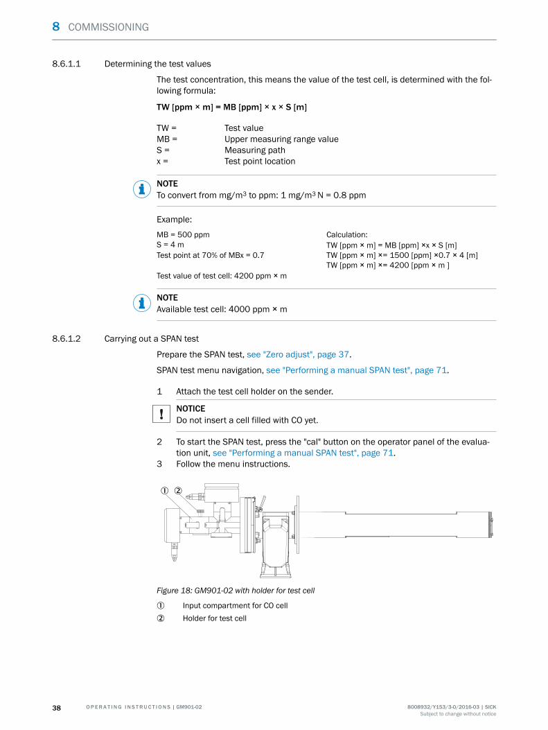
1 Attach the test cell holder on the sender.
NOTICEDo not insert a cell filled with CO yet.
2 To start the SPAN test, press the "cal" button on the operator panel of the evalua‐tion unit, see "Performing a manual SPAN test", page 71.
3 Follow the menu instructions.
1 2
Figure 18: GM901-02 with holder for test cell
1 Input compartment for CO cell2 Holder for test cell
8 COMMISSIONING
38 O P E R A T I N G I N S T R U C T I O N S | GM901-02 8008932/Y153/3-0/2016-03 | SICKSubject to change without notice

8.6.2 Online SPAN test according to EPA Guidelines
Criterion for EPA-compliant SPAN test
• GPP (Gas-Permeation-Probe) with– Connection for gas inlet– Connection for pressure monitoring in the gas measuring chamber
Filling test or zero gas creates an overpressure in the filter element. As soon as theoverpressure is high enough, it presses the exhaust gas out of the filter. This switchesthe gas flow through the filter element to the opposite direction. This method serves todetermine the zero point and various other test points when using suitable test gases.
8.6.2.1 Carrying out a manual EPA SPAN test
Material required Characteristics
Test gas cylinders according to the applicable EPAGuideline (N2 and test gases)
The concentration depends on the upper measuringrange values to be tested
Adjustable pressure regulator for zero gas and SPANgas
With adjustable pressure valve
1/8" line with Swagelok screw fitting Length: Approx. 1.5 m
Pressure gauge • An absolute pressure of 900–1100 mbar(equivalent to the pressure in the duct)
• Scale: 0.5 mbar
• 1/8" Swagelok connection
P
maintcalpardiag
GM 901Evaluation UnitCO
mg/m3236
Ref. conditionsHum: wet
Measuring OperationServiceWarningMalfunction
1
ß987
6
42
3
à
á
5
Figure 19: Equipment for the manual SPAN test
1 Test gas2 Pressure gauge 13 Pressure regulator4 Shut-off valve
COMMISSIONING 8
8008932/Y153/3-0/2016-03 | SICK O P E R A T I N G I N S T R U C T I O N S | GM901-02 39Subject to change without notice

5 Pressure gauge 26 GPP measuring probe7 2 m line (CAN bus and power supply)8 115 V / 230 V9 Temperature sensorß Evaluation unità Analog/status signalsá 115/230V
Preparations
1 Connect the pressure regulator and pressure gauges to the gas cylinders, securethe gas cyclinders.
2 Close the shut-off valve.3 Fit the hose between the pressure regulator and one of the two GPP connections.4 Set the pressure on the gas cylinders to the calculated primary pressure.
NOTEAir is suctioned into the partial vacuum channels as soon as the gas connection isopened. The measured values approach zero depending on the partial vacuumpresent.
5 Connect a pressure gauge to the second gas connection.6 Read off the current measured values on the evaluation unit display.
Measurement
1 Start the EPA-SPAN test per menu, see "SPAN test according to EPA Guidelines",page 72, or digital input.
2 Set T90 to 10 seconds.3 Open the shut-off valve fully.4 Observe the measured values on the display until the value is stable.5 Read off the pressure on the second pressure gauge to correct measurement
when necessary.6 Close the valve on the pressure reducer and the gas cylinder.7 Now terminate data recording and start the evaluation.8 Reset the T90 value.9 Return to measuring mode.10 When required, repeat the procedure (preparation and measurement) with further
test gases.
8.6.2.2 Carrying out a thermal adjustment
The cold test gas flow withdraws energy from the measuring probe body as it flowsthrough the device. Long purge times can therefore effect a difference between the testgas temperature and the process temperature. The following factors influence the dif‐ference:
• Throughflow volumes of the test gas• Measurement duration• Gas velocity in the process
This is the reason why it is recommended to determine the SPAN points first and thenthe zero point because a temperature drop does not influence the zero point measure‐ment. A break between the measurements and the reduction in gas flow reduce thiseffect.
8 COMMISSIONING
40 O P E R A T I N G I N S T R U C T I O N S | GM901-02 8008932/Y153/3-0/2016-03 | SICKSubject to change without notice

8.6.2.3 One-off preliminary measurement/determining the basic setting
Each GPP measuring probe has certain production tolerances. The ideal pressureparameters for the test must be determined once before the first measurement. TheGPP must be installed in the duct for this test because the length of the measuringchamber and velocity of the exhaust gases in the duct also influence the initial pres‐sure settings.
Carrying out a one-off determination of the basic settings
1 Prepare the gas (e.g. N2 or air), see "Carrying out a manual EPA SPAN test",page 39.
2 Start the EPA test, see "Carrying out a manual EPA SPAN test", page 39.3 Set T90 to 10 seconds.4 Observe the display.5 Set the pressure regulator on the gas cylinder to 0 bar and observe the measured
values.6 Set the pressure on the pressure regulator to approx. 3 bar and observe the meas‐
ured values.7 If zero is not reached within a certain time (depending on the T90 settings of the
measuring system), increase the pressure in steps until zero is stable.8 When zero is stable, reduce the pressure in small steps again and observe the dis‐
play.9 Increase the pressure again by 0.5 bar when the display rises above zero again.10 Note the values on gauges 1 and 2.
NOTEThese values can be used later as prelimiinary pressure settings.The correct test gas pressure is typically between 4 mbar and 10 mbar above theprocess pressure.
11 Reset the T90 value.12 Close the shut-off valve and gas cylinder.13 Return to measuring mode.
8.6.3 Automatic SPAN test
The calibration test is carried out with different equipment depending on customerrequirements.
NOTICEValve control as well as triggering a SPAN test must be carried out with an automaticcalibration test unit from the customer.
Equipment for an automatic SPAN test
• Low requirements:1 Determine the pressure settings required before starting the test.2 Connect test gas via solenoid valves to the GPP inlet.3 Use a gauge to set the preliminary pressure settings on the gas cylinder.
NOTEChanges to the flow resistance in the filter can cause pressure rises or dropsthat then influence measuring precision (gas law).
• High requirements:1 Connect test gas via solenoid valves and adjustable pressure regulator to the
GPP inlet.
COMMISSIONING 8
8008932/Y153/3-0/2016-03 | SICK O P E R A T I N G I N S T R U C T I O N S | GM901-02 41Subject to change without notice

b The pressure regulator serves to keep the pressure in the measuringchamber constant.
b The control signal is generated by comparing the fine pressure measure‐ment in the chamber with a value previously specified.
NOTEChanges in the filter material influence the time required for purging.
8 COMMISSIONING
42 O P E R A T I N G I N S T R U C T I O N S | GM901-02 8008932/Y153/3-0/2016-03 | SICKSubject to change without notice

8.7 Basic parameters set
Parameter settingsPhysical unit mg/Nm3
Normalization wetResponse time 30 sMeasuring range 1000 mg/Nm3
Limit value 1000 mg/Nm3
Measuring distanceActive measuring distance 250 or 500 mm
TemperatureSubstitute 150 °CExternal Analog inScale low 0 °CScale high 250 °CInput low 4.0 mAInput high 20.0 mA
HumiditySubstitute 00.0 % (Vol.)
PressureSubstitute 1013 hPa (change the value to the current value
when measuring in ppm)
Analog outLive zero 4 mA
CalibrationSpan 1.00Zero +000
Device parametersSerial number Current software versionEvaluation unit Current software versionConfiguration Type key of evaluation unit
ServiceC1 Determined during zero adjustC2 Determined during zero adjustC3 Data specified at the factory and assigned to the
GM901-02 receiver (individual, per device).C4C5C6C7C8
COMMISSIONING 8
8008932/Y153/3-0/2016-03 | SICK O P E R A T I N G I N S T R U C T I O N S | GM901-02 43Subject to change without notice

8.8 Installing the sender and receiver
Step 1: Fit the T-piece on the probe
b Fit the T-piece on the flange attachment of the measuring probe.
Figure 20: Fitting the T-piece on the measuring probe
NOTEThe probe is normally delivered from the factory already fitted on the T-piece.
Step 2: Align the sender on the optical axis
b The adjustment device, see "Accessories ", page 16, with the lamp must be fittedat the sender position and the adjustment device with the focusing screen at thereceiver position.
b On the sender, tighten the two nuts for horizontal adjustment (X) and verticaladjustment (Y) so that the light point shown is positioned centered on the focusingscreen of the adjustment tube.
Ë É
Figure 21: Light point on the focusing screen
Step 3: Align the receiver on the optical axis
b On the receiver, tighten the two nuts for horizontal adjustment (X) and verticaladjustment Y) so that the light point shown is positioned centered on the focusingscreen of the adjustment tube.
b Control the adjustment in both directions.
8 COMMISSIONING
44 O P E R A T I N G I N S T R U C T I O N S | GM901-02 8008932/Y153/3-0/2016-03 | SICKSubject to change without notice

Step 4: Fit the sender and receiver on the T-piece
b Fit the sender and receiver on the T-piece and secure both with the quick-releaseclamps.
1
Figure 22: Fitting the sender and receiver on the T-piece
1 Quick-release clamps
Step 5: Connect the signal lines and gas-carrying lines
b Connect the lines as shown in the diagram, see "Connection diagram for standardversion", page 27.
Step 6: Warm the device up
b Switch the power supply on and let the device warm up for 30 minutes.
CAUTIONUnstable measured values through shortened warming up time (GPP measuringprobe)If the GPP measuring probe is not warm enough, condensate deposits on the opti‐cal surfaces can lead to false measuring results. Time-consuming cleaning of theoptical surfaces is then necessary.
b Always maintain the 30 minute warming up time.
Step 7: Perform the zero adjust
see "Performing zero adjust", page 70.
COMMISSIONING 8
8008932/Y153/3-0/2016-03 | SICK O P E R A T I N G I N S T R U C T I O N S | GM901-02 45Subject to change without notice

Step 8: Install the GM901 measuring device on the duct
DANGERHealth risk through hot or toxic gases/dusts in the measuring channelThe measuring duct can contain hot or toxic gases or dust deposits which can escapewhen opening the duct-side flange. Even if the measuring duct is out of operation dur‐ing the installation, escaping gases can lead to severe damage to health.
b Always put the measuring duct out of operation for the duration of the installation.b If required, purge the measuring duct with ambient air before starting installation
work.b Always wear suitable or company-specified protective clothing during installation
work.
CAUTIONDevice damage through incorrect/missing insulation of the duct when the measuringchannel is hot
b When the gas duct is hot, insulate the duct and flanges so that the device is pro‐tected from high temperatures.
1 If present, remove the cover on the duct-side flange with tube.2 Insert the measuring probe with mounted SR-unit in the duct-side flange with
tube.
NOTICEA seal must be present between the device flange and the duct flange.
3 Fit the measuring probe with the fastening set delivered on the duct-side flange.The fastening set comprises 4 screws (M16 x 60), each with nut and 2 washers.
CAUTIONAvoid damage to the device
■ GMP measuring probe: Ensure uninterrupted purge air feed to the measuringprobe!
■ GPP probe: Ensure uninterrupted power supply to the measuring probe to heat theoptical surfaces!
8 COMMISSIONING
46 O P E R A T I N G I N S T R U C T I O N S | GM901-02 8008932/Y153/3-0/2016-03 | SICKSubject to change without notice

1
2
3
4
Figure 23: Installing the device on the duct flange
1 Seal2 Screws M16x60 with nuts and washers3 Flange with tube (duct-side)4 Purge air unit SLV4
NOTEElectrical connections and alignment control, see "Connection diagram with terminalbox (detached evaluation unit)", page 30 and see "Zero adjust", page 37.
COMMISSIONING 8
8008932/Y153/3-0/2016-03 | SICK O P E R A T I N G I N S T R U C T I O N S | GM901-02 47Subject to change without notice

8.9 Connecting the sender and receiver with a CAN line
NOTEThe two connection plugs of the CAN cable are configured so that they only fit on thesuitable connection. The connection sequence is unimportant.
Figure 24: Connecting the CAN line between sender and receiver
1 CAN connection on GM901 sender2 CAN connection on GM901 receiver
8 COMMISSIONING
48 O P E R A T I N G I N S T R U C T I O N S | GM901-02 8008932/Y153/3-0/2016-03 | SICKSubject to change without notice

8.10 Installing the weatherproof cover
The weatherproof cover is installed in two steps:
1 Fit the installation plate on the flange of the purge air fixture and the measuringprobe flange.
2 Place the weatherproof cover on the installation plate.
1 Fit the installation plate on the flange of the purge air fixture:w Lay the weatherproof cover upside down on the floor.w Open and unhinge the locks on both sides.w Pull the installation plate upwards and remove it from the cover.
Figure 25: Removing the installation plate
1 Installation plate2 Lock3 Top mounting ring4 Bottom mounting ring
w Remove the bottom mounting ring.w Place the installation plate on the rubber band of the purge air fixture from
the top.w Position the mounting ring on the side of the purge air fixture.w Screw the bottom mounting ring and the top mounting ring together.
COMMISSIONING 8
8008932/Y153/3-0/2016-03 | SICK O P E R A T I N G I N S T R U C T I O N S | GM901-02 49Subject to change without notice

12
3
4
Figure 26: Detail view: Positioning the top mountingring on the side of the purge air fixture
1 Installation plate2 Top mounting ring3 Bottom mounting ring
2 Place the weatherproof cover on the installation plate:w Position the cover on the installation plate from the top.w Engage the locks and close again.
Figure 27: Placing the weatherproof cover on theinstallation plate
8 COMMISSIONING
50 O P E R A T I N G I N S T R U C T I O N S | GM901-02 8008932/Y153/3-0/2016-03 | SICKSubject to change without notice

9 Operation
9.1 Safety
WARNINGDanger for persons and system caused by unsafe operation of the measuring systemIf the device is or could be in an unsafe state:
b Put the device out of operation.b Disconnect the device from the main power supply and signal voltage.b Prevent unauthorized or unintentional start-up.
9.2 Operating and display elements
9.2.1 LEDs
LED Significance / possible cause
OPERATION
• Measuring mode
• The device is switched on, power voltage is available
SERVICE
• Service mode
Warning
• Warning message
• At least one warning message pending
• Reading warning messages, see Diagnosis mode (diag)
MALFUNCTION
• Device malfunction
• At least one malfunction message pending
• Reading malfunction messages, see Diagnosis mode (diag)
Table 9: Significance of LEDs
OPERATION 9
8008932/Y153/3-0/2016-03 | SICK O P E R A T I N G I N S T R U C T I O N S | GM901-02 51Subject to change without notice

9.2.2 Operator panel of the evaluation unit GM901
GM 901Evaluation UnitCO
ppm 564
CO
ppm
0
CO
CO
H O
Ref. conditionsHum: wet
maint
Measuring
Measuring T=150 °C
Enter meas
maintcalpardiag
Operation
Service
Warning
Malfunction
GM 901Evaluation UnitCO
mg/Nm³ 564
CO
mg/Nm³
0
CO
CO
H O
Ref. conditionsHum: wet
maint
Measuring
Measuring T=150 °C
Enter meas
maintcalpardiag
Operation
Service
Warning
Malfunction 1000 0
2
3
4 5
6
789 ß à á
â ã
maintcalpardiag
GM 901
Evaluation UnitCO
mg/Nm3
564
Measuring T= 150 °COperation
Service
Warnin
Malfunction 1000 0
Enter meas
Figure 28: Operator panel GM901-02 EvU
Function buttons
1 GM901 evaluation unit (cast housing version)
2 Operator panel of the evaluation unit
3 Arrow buttons to edit units/digits
• Left arrow:– Move cursor to the left– Abort and return button
• Right arrow:– Move cursor to the right
• Up arrow:– Move cursor upwards– Increase digits
• Down arrow:– Move cursor downwards– Decrease digits
4 Current measured value
5 Measured value of an external temperature sensor or an internal adjustable value
6 Adjustable limit value
7 Measuring range end value, adjustable
8 Measuring range start value, adjustable
Function buttons and submenus
9 Diagnosis chapter 9.4.2, "Diagnosis"
ß Parameter see "Parameters (settings)", page 56
à Calibration see "Calibration (Cal)", page 70
■ Zero adjust Zero adjust
■ SPAN test Manual SPAN test
■ EPA SPAN test SPAN test according to EPA Guideline 40C FR 75
á Maintenance Maintenance
■ Reset System Restart system
9 OPERATION
52 O P E R A T I N G I N S T R U C T I O N S | GM901-02 8008932/Y153/3-0/2016-03 | SICKSubject to change without notice
Function buttons
■ Maint Mode Maintenance mode
■ Test analog output Check power value on analog output
■ Test Relays Relay test
■ Reset Parameter1) Set parameters to basic setting Only when instructed to do so by SICK!
â Enter Confirm set value
ã Measurement see "Measuring mode", page 55
Measuring Press "meas" for immediate return to measuring mode
1 The basic setting parameters are default values. All individual settings, including calibration parameters,are overwritten.
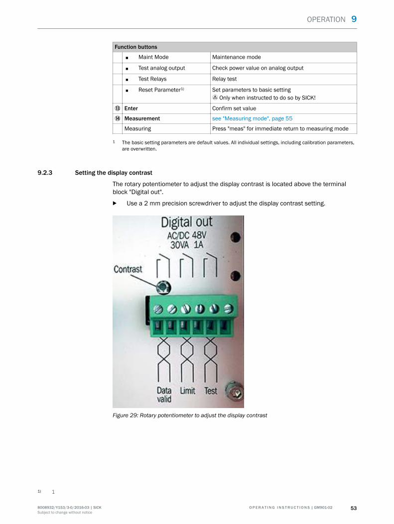
9.2.3 Setting the display contrast
The rotary potentiometer to adjust the display contrast is located above the terminalblock "Digital out".
b Use a 2 mm precision screwdriver to adjust the display contrast setting.
Figure 29: Rotary potentiometer to adjust the display contrast
1) 1
OPERATION 9
8008932/Y153/3-0/2016-03 | SICK O P E R A T I N G I N S T R U C T I O N S | GM901-02 53Subject to change without notice

9.3 Entering the password
■ The password is always prompted for when a parameter is to be changed.■ The password is "1234".■ The password remains active for 30 minutes.
DANGEREndangerment of system safety through parameters with incorrect settingsEntering the password allows parameters to be changed. Unauthorized changes tosafety-relevant parameters can lead to unsafe operation of the measuring system andcan thereby endanger plant safety.
b Password entry only by technicians.
Password0 0 0 0
back select
Password:
Password1 0 0 0
back select
Password:
Password1 0 0 0
back select
Password:
2 x Password1 2 0 0
back select
Password:
...
Password1 2 3 4
back select
Password:
Figure 30: Entering the password
9 OPERATION
54 O P E R A T I N G I N S T R U C T I O N S | GM901-02 8008932/Y153/3-0/2016-03 | SICKSubject to change without notice

9.4 Menus
9.4.1 Measuring mode
meas
The measuring mode display is shown during active measuring operation. The "Opera‐tion" LED is green. Explanations on the measuring mode display, see "Operator panel ofthe evaluation unit GM901", page 52.
The operator can switch directly to the measuring mode display from every menu item:
b Press "meas".
9.4.2 Diagnosis
Menu item "Diagnosis" serves to view the following data:
■ Error messages■ Warning messages■ Sensor values
b Press "Diag" on the operator panel of the evaluation unit to call up the submenuitems.
9.4.2.1 Viewing error messages
ParametersMalfunction 1 of 1
back
Signal too high
Diagnosis
back
Measuring T=150 °CMeasuring T=150°C
0 1000
CO 564ppm
Figure 31: Viewing error messages (example)
NOTETable of all error messages, see "Malfunction messages", page 80.
OPERATION 9
8008932/Y153/3-0/2016-03 | SICK O P E R A T I N G I N S T R U C T I O N S | GM901-02 55Subject to change without notice
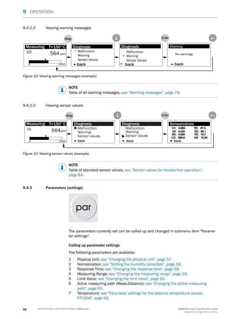
9.4.2.2 Viewing warning messages
Measuring T=150 °CMeasuring T=150°C
0 1000
CO 564 ppm
DiagnosisDiagnosisMalfunction
Sensor ValuesWarning
backback back
Malfunction
Sensor ValuesWarning No warnings
Figure 32: Viewing warning messages (example)
NOTETable of all warning messages, see "Warning messages", page 79.
9.4.2.3 Viewing sensor values
Measuring T=150 °CMeasuring T=150°C
0 1000
CO 564ppm
ParametersV1: 3.600 TE: 57.0V1: 3.600 TE: 57.0
Sensorvalues
V2: 4.200 TO: 60.1V2: 4.200 TO: 60.1DK: 0.000 TD: 10.7DK: 0.000 TD: 10.7CC: 500.0 AG: 12.04CC: 500.0 AG: 12.04
ParametersMalfunctionWarning
Diagnosis
Sensor values b
ParametersMalfunctionWarning
Diagnosis
Sensor values
b
back back back
Figure 33: Viewing sensor values (example)
NOTETable of standard sensor values, see "Sensor values for trouble-free operation",page 84.
9.4.3 Parameters (settings)
The parameters currently set can be called up and changed in submenu item "Parame‐ter settings".
Calling up parameter settings
The following parameters are available:
1 Physical Unit: see "Changing the physical unit", page 572 Normalization: see "Setting the humidity correction", page 58.3 Response Time: see "Changing the response time", page 58.4 Measuring Range: see "Changing the measuring range", page 59.5 Limit Value: see "Changing the limit value", page 60.6 Active measuring path (Meas.Distance): see "Changing the active measuring
path", page 60.7 Temperature: see "Parameter settings for the external temperature sensor
PT1000", page 60.
9 OPERATION
56 O P E R A T I N G I N S T R U C T I O N S | GM901-02 8008932/Y153/3-0/2016-03 | SICKSubject to change without notice

8 Humidity: see "Setting the humidity content in sample gas", page 64.9 Pressure: see "Setting the sample gas pressure", page 64.10 Analog Out: see "Changing the Live Zero value of the analog output (Analog Out)",
page 65.11 Calibration: see "Changing the calibration values", page 65.
Measuring T=150 °CMeasuring T=150°C
0 1000
CO 564ppm
Parameters
back
PhysicalNormalization
Parameter Settings
Response TimeMeasuringRange
ParametersSettingsDevice
Parameter
Service
UnitParameters
Unit : mg/ Nm³
Physical Unit
edit:Enterbackback
Figure 34: Path from Measuring Screen to change parameters (example)
b Press "Enter" in the display for current parameter setting.b Enter the password, 9.3 "Entering the password", page 54b Press "Left arrow" after entering the new value.
Menu "Parameter Settings" is displayed again.
9.4.3.1 Changing the physical unit
Submenu item "Physical Unit" serves to set the physical unit for the CO value output.Available are:
• ppm• mg/m3N• mg/m3
1 Follow the menu path as described, see "Parameters (settings)", page 56.2 Enter the password, see "Entering the password", page 54.3 Enter the changes.4 Confirm value with "Enter".5 Press the "Left arrow" to return to menu item "Parameter Settings".
Parameters
back
Unit : ppmPhysical Unit
edit:Enter
Parameters
back
Physical Unit
selectppm mg/Nm³ mg/m³
Parameters
back
Physical Unit
edit: Enter
Unit : ppm Unit : mg/ Nm³Parameters
back
Physical Unit
selectppm mg/Nm³ mg/m³Unit : mg/ Nm³
Figure 35: Changing the physical unit
OPERATION 9
8008932/Y153/3-0/2016-03 | SICK O P E R A T I N G I N S T R U C T I O N S | GM901-02 57Subject to change without notice

9.4.3.2 Setting the humidity correction
Submenu item "Normalization" serves to set whether the measured value is output cal‐culated as "wet" or "dry". The default value entered for H2O is used here, see "Settingthe humidity content in sample gas", page 64.
The damp correction is activated when "wet" is set. Available are:
• dry• wet
1 Follow the menu path as described, see "Parameters (settings)", page 56.2 Enter the password, see "Entering the password", page 54.3 Enter the changes.4 Confirm value with "Enter".5 Press the "Left arrow" to return to menu item "Parameter Settings".
Parameters
back
Mode: dryNormalization
edit: Enter select
Parameters
back
Mode:Normalization
dry wet
select
Parameters
back
Mode:Normalization
dry wet
Parameters
back
Mode: wetNormalization
edit: Enter
Figure 36: Selecting the humidity correction
9.4.3.3 Changing the response time
Submenu item "Response Time" serves to change the response time.
NOTEFactory setting: 30 s.Allowable values: 5 ... 360 s.Contact SICK Service when you are not sure which response time should be set.
1 Follow the menu path as described, see "Parameters (settings)", page 56.2 Enter the password, see "Entering the password", page 54.3 Enter the changes.4 Confirm value with "Enter".5 Press the "Left arrow" to return to menu item "Parameter Settings".
Parameters
back
Time: 30 sResponse Time
edit:Enter
Parameters
back
Response TimeTime: 030 s
select
Parameters
back
Response Time
Time: 030 s
select
Parameters
back
Response TimeTime: 040 s
select
Parameters
back
Time: 40 sResponse Time
edit:Enter
Figure 37: Changing the response time (example)
9 OPERATION
58 O P E R A T I N G I N S T R U C T I O N S | GM901-02 8008932/Y153/3-0/2016-03 | SICKSubject to change without notice

9.4.3.4 Changing the measuring range
Submenu item "Measuring Range" serves to change the measuring range currently set.
NOTEFactory setting: 1000 ppmAllowable values on the device: 100 ... 60 000 ppmContact SICK Service when you are not sure which value should be set for your measur‐ing range.
1 Follow the menu path as described, see "Parameters (settings)", page 56.2 Enter the password, see "Entering the password", page 54.3 Enter the changes.4 Confirm value with "Enter".5 Press the "Left arrow" to return to menu item "Parameter Settings".
Parameters
back
1000 ppm Measuring Range
edit:Enter back select
Parameters
back
Range: 01000 ppm
select
Parameters
back select
Parameters
back edit:Enter
Measuring Range Measuring Range
Measuring Range Measuring Range
Range: Range:
Range: Range: 1100 ppm
01000 ppm
01000 ppmParameters
back select
Measuring Range
Range: 01100 ppm
Figure 38: Changing the measuring range (example)
OPERATION 9
8008932/Y153/3-0/2016-03 | SICK O P E R A T I N G I N S T R U C T I O N S | GM901-02 59Subject to change without notice

9.4.3.5 Changing the limit value
Submenu item "Limit Value" serves to change the limit value currently set.
NOTEFactory setting: 1000 ppm.Attention: The value must be within the selected measuring range.Contact SICK Service when you are not sure which value should be set for your measur‐ing range.
1 Follow the menu path as described, see "Parameters (settings)", page 56.2 Enter the password, see "Entering the password", page 54.3 Enter the changes.4 Confirm value with "Enter".5 Press the "Left arrow" to return to menu item "Parameter Settings".
Parameters
back
1000 ppm
Limit Value
edit: Enter back select
Parameters
back
Limit: 01000 ppm
select
Parameters
back select back edit:Enter
Limit Value Limit Value
Limit Value
Limit: Limit:
Limit Limit: 1100 ppm
01000 ppm
01000 ppmParameters
back select
Limit Value
Limit: 01100 ppmLimit Value
Figure 39: Setting the limit value (example)
9.4.3.6 Changing the active measuring path
Submenu item "Meas.Distance" serves to enter or change the value for the activemeasuring path.
WARNINGAdjusting the value for the active measuring path can lead to incorrect measuringresultsThe value set at the factory corresponds to the measuring path of the delivered meas‐uring probe.
b Contact SICK Service when you want to change the values.
9.4.3.7 Parameter settings for the external temperature sensor PT1000
Submenu item "Temperature Input" serves to check and change the following settings.
■ Substitute: Default temperature value when the temperature sensor fails■ External: Using an external temperature sensor■ Scale Low: Lower limit value for the sample gas temperature■ Scale High: Upper limit value for the sample gas temperature■ Input Low: mA signal for the lower limit value of the sample gas temperature■ Input High: mA signal for the upper limit value of the sample gas temperature
9 OPERATION
60 O P E R A T I N G I N S T R U C T I O N S | GM901-02 8008932/Y153/3-0/2016-03 | SICKSubject to change without notice

NOTEThe values are preset in the 20 mA converter.
Measuring T=150 °CMeasuring T=150°C
0 1000
CO 564ppm
Parameters
back
Measuring RangeLimit Value
Parameter Settings
Meas. DistanceTemperature
par
Parameters
back
SettingsDevice
Parameter
Service
Parameters
back
Substitute : 150°CExternal :Scale Low 0 °CScale High : 250 °C
Edit: Enter
Input Low: 4,0 mAInput High : 20,0
Temperature Input
Yes
:
:
mA
+
Figure 40: Setting the parameters for the temperature sensor PT1000
9.4.3.7.1 Changing the default temperature value
Submenu item "Substitute" serves to enter the default temperature value. The measur‐ing system uses this value as temperature value when:
• The external temperature sensor fails.• The temperature measurement is outside the configured upper limit value. The
device outputs a warning message in this case.
NOTEFactory setting: 150 °CAllowable values: ? ... 430 °CContact SICK Service when you are not sure which temperature value should be set.
1 Follow the menu path as described, see "Parameter settings for the external tem‐perature sensor PT1000", page 60.
2 Enter the password, see "Entering the password", page 54.3 Enter the changes.4 Confirm value with "Enter".5 Press the "Left arrow" to return to menu item "Parameter Settings".
back
Substitute : 150°CExternal :Scale Low : 0 °CScale High : 250 °C
Edit: Enter
Temperature Input
AnaIn
back
Substitute : 150°CExternal :Scale Low : 0 °CScale High : 250 °C
Edit: Enter
Temperature Input
AnaIn
back
Substitute : 150°CExternal :Scale Low : 0 °CScale High : 250 °C
Edit: Enter
Temperature Input
AnaIn
back
Substitute : 160°CExternal :Scale Low : 0 °CScale High : 250 °C
Edit: Enter
Temperature Input
AnaIn
Figure 41: Setting the default temperature setting (example)
9.4.3.7.2 Setting the use of an external temperature sensor
Submenu item "External" serves to set a "Yes"/"No" switch as to whether an externaltemperature sensor (PT1000) is used. The signal runs via an analog input. "Analn" isshown when the switch is set to "Yes".
1 Follow the menu path as described, see "Parameter settings for the external tem‐perature sensor PT1000", page 60.
2 Enter the password, see "Entering the password", page 54.3 Enter the changes.
OPERATION 9
8008932/Y153/3-0/2016-03 | SICK O P E R A T I N G I N S T R U C T I O N S | GM901-02 61Subject to change without notice

4 Confirm value with "Enter".5 Press the "Left arrow" to return to menu item "Parameter Settings".
back
Substitute : 150°CExternal :Scale Low : 0 °CScale High : 250 °C
Edit: Enter
Temperature Input
No
back
Substitute : 150°CExternal :Scale Low : 0 °CScale High : 250 °C
Edit: Enter
Temperature Input
Yes
back
Substitute : 150°CExternal :Scale Low : 0 °CScale High : 250 °C
Edit: Enter
Temperature Input
Yes
back
Substitute : 150°CExternal :Scale Low : 0 °CScale High : 250 °C
Edit: Enter
Temperature Input
AnaInNo No
Figure 42: Activating the use of an external temperature sensor
9.4.3.7.3 Setting the temperature range: Lower limit value
Submenu item "Scale Low" serves to set the lower limit value for the sample gas tem‐perature. The lower limit value corresponds to Live Zero.
NOTEFactory setting: 0 °CAllowable values: See Technical DataContact SICK Service when you are not sure which limit value should be set.
1 Follow the menu path as described, see "Parameter settings for the external tem‐perature sensor PT1000", page 60.
2 Enter the password, see "Entering the password", page 54.3 Enter the changes.4 Confirm value with "Enter".5 Press the "Left arrow" to return to menu item "Parameter Settings".
back
Substitute : 150°CExternal :Scale Low : 0 °CScale High : 250 °C
Edit: Enter
Temperature Input
AnaIn
back
Substitute : 150°CExternal :Scale Low :Scale High : 250 °C
Temperature Input
AnaIn
back
Substitute : 150°CExternal :Scale Low :Scale High : 250 °C
Temperature Input
AnaIn
back
Substitute : 150°CExternal :Scale Low :Scale High : 250 °C
Temperature Input
AnaIn
000 °C000 °C
2 x 5 x
005 °C
back
Substitute : 150°CExternal :Scale Low : 5 °CScale High : 250 °C
Edit: Enter
Temperature Input
AnaIn
Select Select
Select
Figure 43: Setting the lower limit value for the temperature range (example) (corresponds to LiveZero)
9.4.3.7.4 Setting the temperature range: Upper limit value (20 mA)
Submenu item "Scale High" serves to set the upper limit value for the sample gas tem‐perature.
NOTEFactory setting: 250 °CAllowable values: Max. 500 °CContact SICK Service when you are not sure which limit value should be set.
9 OPERATION
62 O P E R A T I N G I N S T R U C T I O N S | GM901-02 8008932/Y153/3-0/2016-03 | SICKSubject to change without notice
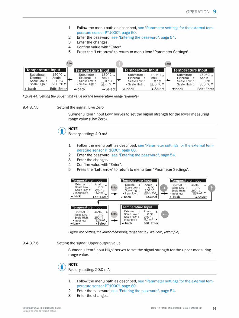
1 Follow the menu path as described, see "Parameter settings for the external tem‐perature sensor PT1000", page 60.
2 Enter the password, see "Entering the password", page 54.3 Enter the changes.4 Confirm value with "Enter".5 Press the "Left arrow" to return to menu item "Parameter Settings".
back
Substitute : 150°CExternal :Scale Low : 0 °CScale High : 250 °C
Edit: Enter
Temperature Input
AnaIn
Parameters
back
Substitute : 150°CExternal :Scale Low :Scale High : 250 °C
Temperature Input
AnaIn
back
Substitute : 150°CExternal :Scale Low :Scale High : 350 °C
Select
Temperature Input
AnaIn 0 °C 0 °C
back
Substitute : 150°CExternal :Scale Low : 0 °CScale High : 350 °C
Edit: Enter
Temperature Input
AnaIn
Select
Figure 44: Setting the upper limit value for the temperature range (example)
9.4.3.7.5 Setting the signal: Live Zero
Submenu item "Input Low" serves to set the signal strength for the lower measuringrange value (Live Zero).
NOTEFactory setting: 4.0 mA
1 Follow the menu path as described, see "Parameter settings for the external tem‐perature sensor PT1000", page 60.
2 Enter the password, see "Entering the password", page 54.3 Enter the changes.4 Confirm value with "Enter".5 Press the "Left arrow" to return to menu item "Parameter Settings".
back
External :Scale Low : 0 °CScale High : 250 °C
Edit: Enter
Temperature InputAnaIn
back
Temperature Input
back
Temperature Input
back
Temperature Input
back Edit: Enter
Temperature Input
Select Select
Select
Input low : 4,0 mA
External :Scale Low : 0 °CScale High : 250 °C
AnaIn
Input low : 04,0 mA
External :Scale Low : 0 °CScale High : 250 °C
AnaIn
Input low : 04,0 mA
External :Scale Low : 0 °CScale High : 250 °C
AnaIn
Input low : 05,0 mA
External :Scale Low : 0 °CScale High : 250 °C
AnaIn
Input low : 5,0 mA
Figure 45: Setting the lower measuring range value (Live Zero) (example)
9.4.3.7.6 Setting the signal: Upper output value
Submenu item "Input High" serves to set the signal strength for the upper measuringrange value.
NOTEFactory setting: 20.0 mA
1 Follow the menu path as described, see "Parameter settings for the external tem‐perature sensor PT1000", page 60.
2 Enter the password, see "Entering the password", page 54.3 Enter the changes.
OPERATION 9
8008932/Y153/3-0/2016-03 | SICK O P E R A T I N G I N S T R U C T I O N S | GM901-02 63Subject to change without notice
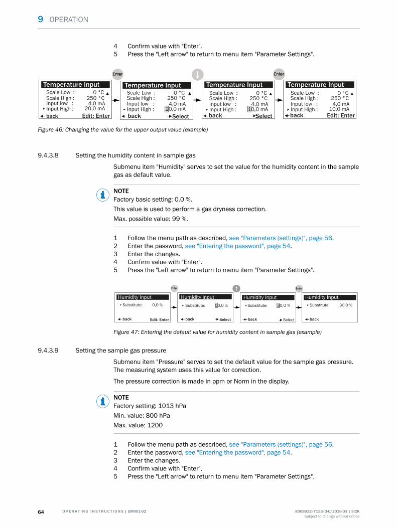
4 Confirm value with "Enter".5 Press the "Left arrow" to return to menu item "Parameter Settings".
back
Scale Low : 0 °CScale High : 250 °C
Edit: Enter
Temperature Input
back
Temperature Input
back
Temperature Input
Select Select
Input low : 4,0 mAInput High : 20,0 mA
Scale Low : 0 °CScale High : 250 °CInput low : 4,0 mAInput High : 20,0 mA
Scale Low : 0 °CScale High : 250 °CInput low : 4,0 mAInput High : 10,0 mA
back
Temperature InputScale Low : 0 °CScale High : 250 °CInput low : 4,0 mAInput High : 10,0 mA
Edit: Enter
Figure 46: Changing the value for the upper output value (example)
9.4.3.8 Setting the humidity content in sample gas
Submenu item "Humidity" serves to set the value for the humidity content in the samplegas as default value.
NOTEFactory basic setting: 0.0 %.This value is used to perform a gas dryness correction.Max. possible value: 99 %.
1 Follow the menu path as described, see "Parameters (settings)", page 56.2 Enter the password, see "Entering the password", page 54.3 Enter the changes.4 Confirm value with "Enter".5 Press the "Left arrow" to return to menu item "Parameter Settings".
back
Substitute: 0,0 %
Edit: Enter
Humidity Input
back
Humidity Input
back
Humidity Input
Select Select back
Humidity Input
Edit: Enter
Substitute: 00,0 % Substitute: 30,0 % Substitute: 30,0 %
Figure 47: Entering the default value for humidity content in sample gas (example)
9.4.3.9 Setting the sample gas pressure
Submenu item "Pressure" serves to set the default value for the sample gas pressure.The measuring system uses this value for correction.
The pressure correction is made in ppm or Norm in the display.
NOTEFactory setting: 1013 hPaMin. value: 800 hPaMax. value: 1200
1 Follow the menu path as described, see "Parameters (settings)", page 56.2 Enter the password, see "Entering the password", page 54.3 Enter the changes.4 Confirm value with "Enter".5 Press the "Left arrow" to return to menu item "Parameter Settings".
9 OPERATION
64 O P E R A T I N G I N S T R U C T I O N S | GM901-02 8008932/Y153/3-0/2016-03 | SICKSubject to change without notice

Substitute: 1013 hPa
back
Substitute: 1013 hPa
Edit: Enter
Pressure Input
back
Pressure Input
back
Pressure Input
Select Select
back
Pressure InputParameters
backback
Meas. DistanceMeas. Distance
Parameter Settings
backback
TemperatureTemperature
Limit ValueLimit Value
HumidityHumidity
Substitute: 1013hPa
Substitute: 1113 hPa
back
Pressure Input
Select
Substitute: 1113hPa
Edit: Enter
Figure 48: Entering the default value for the sample gas pressure (example)
9.4.3.10 Changing the Live Zero value of the analog output (Analog Out)
Submenu item "Analog Out" serves to change the Live Zero value.
NOTEFactory setting: 4 mAMin. value: 0 mAMax. value: 4 mA
1 Follow the menu path as described, see "Parameters (settings)", page 56.2 Enter the password, see "Entering the password", page 54.3 Enter the changes.4 Confirm value with "Enter".5 Press the "Left arrow" to return to menu item "Parameter Settings".
Live Zero : 4 mA
back
Live Zero: 4 mA
edit: Enter
Analog Out
back
Analog Out
back
Analog Out
Select Select
Parameters
backback
Meas. DistanceMeas. Distance
Parameter Settings
backback
TemperatureTemperature
Limit ValueLimit Value
HumidityHumidity
Live Zero: 3 mA
back
Analog Out
Live Zero: 3 mA
edit: Enter
Figure 49: Changing the Live Zero value (example)
9.4.3.11 Changing the calibration values
Submenu item "Calibration" serves to change the characteristic gradient after a spantest and the offset correction for the zero point after a reference measurement duringon-site calibration.
1 Follow the menu path as described, see "Parameters (settings)", page 56.2 Enter the password, see "Entering the password", page 54.3 Enter the changes.4 Confirm value with "Enter".5 Press the "Left arrow" to return to menu item "Parameter Settings".
OPERATION 9
8008932/Y153/3-0/2016-03 | SICK O P E R A T I N G I N S T R U C T I O N S | GM901-02 65Subject to change without notice

SPAN value
Submenu item "Span" serves to adapt the setting for the SPAN after completing theSPAN test.
Factory setting: 1.00
Possible setting range: 0 ... 1,99
back
Span: 1.00
edit: Enter
Calibration
back backselect select
Parameters
backback
Meas. DistanceMeas. Distance
Parameter Settings
backback
TemperatureTemperature
Limit ValueLimit Value
HumidityHumidityback
Zero: 0
Calibration
CalibrationCalibration
Span: 0.00
Span: 0.00Span: 1.00
8 x
back
Span: 0.80
Calibration
back select
Calibration
Span: 0.80Zero: 0Zero: 0Zero: 0
Zero: 0Zero: 0
select select
Figure 50: Changing the SPAN value (example)
Offset correction after zero point measurement
Submenu item "Zero" serves to perform an offset correction after a reference measure‐ment.
• Factory setting: 0
back
Span: 1.00
edit: Enter
Calibration
back back select
Parameters
backback
Meas. DistanceMeas. Distance
Parameter Settings
backback
TemperatureTemperature
Limit ValueLimit Value
HumidityHumidityback
Zero: 0
Calibration
CalibrationCalibration
Span: 1.00
Span: 1.00Span: 1.00
3 x
back
Span: 1.00
Calibration
back
Calibration
Span: 1.00Zero: 2Zero:Zero:
Zero: Zero: 0
select select
edit: Enter
+000
+000 +002
2 x
edit: Enter
Figure 51: Changing the zero point value (example)
9.4.3.12 Device characteristic data (Device)
Menu item "Device" serves to view the device characteristic data entered at the factory.
The following characteristic data are available:
1 Serial Number2 Software Revision3 Configuration
9 OPERATION
66 O P E R A T I N G I N S T R U C T I O N S | GM901-02 8008932/Y153/3-0/2016-03 | SICKSubject to change without notice

Measuring T=150 °CMeasuring T=150°C
0 1000
CO 564ppm
back
Serial NumberParameter Device
Software RevisionConfiguration
par
back
SettingsDevice
Parameters
Service
Figure 52: Path from Measuring Screen to Device Characteristic Data
9.4.3.12.1 Calling up the serial number
Submenu item "Serial Number" serves to retrieve the serial numbers of the measuringdevice and evaluation unit.
NOTEThe respective 8-character serial numbers of the evaluation unit and measuring devicemust match the serial numbers on the type plates.Changing the serial numbers can lead to SICK Service no longer being able to providetechnical support.
back
Serial NumberParameter Device
Software RevisionConfiguration
back
NumberSerial Number
XXXXXXXX
Edit: Enter
Figure 53: Calling up the serial number
9.4.3.12.2 Calling up the software version
Submenu item "Software Revision" serves to retrieve the software version of the meas‐uring device and evaluation unit.
NOTEThis value is updated automatically when Service updates the software. The customercannot change this entry.
back
Serial NumberParameter Device
Software RevisionConfiguration
back
Sensor UnitSoftware Revision
XXXXXXXXXXX
XXXXXXXXXXXEvaluation Unit
Figure 54: Calling up the current software version
9.4.3.12.3 Viewing the device configuration
Submenu item "Configuration" serves to retrieve the code for the device configuration.
OPERATION 9
8008932/Y153/3-0/2016-03 | SICK O P E R A T I N G I N S T R U C T I O N S | GM901-02 67Subject to change without notice
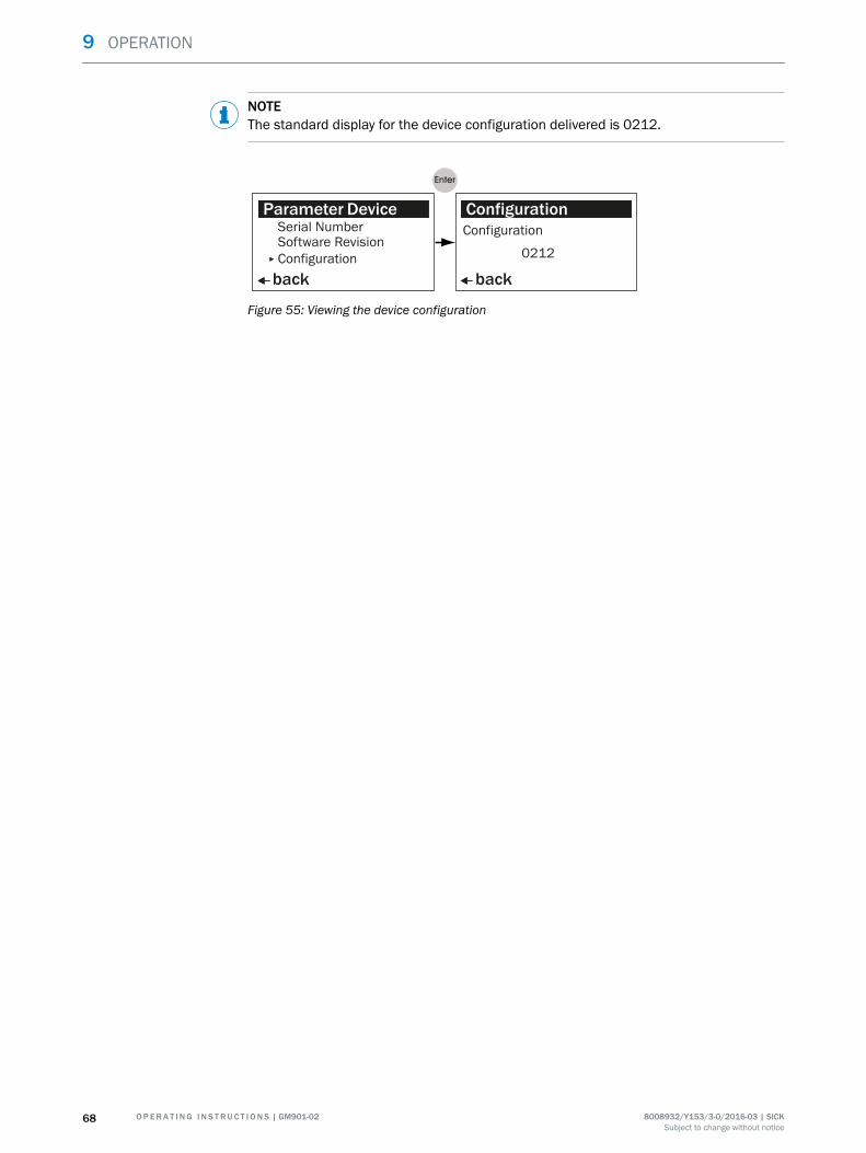
NOTEThe standard display for the device configuration delivered is 0212.
Parameters
back
Serial NumberParameter Device
Software RevisionConfiguration
Parameters
back
ConfigurationConfiguration
0212
Figure 55: Viewing the device configuration
9 OPERATION
68 O P E R A T I N G I N S T R U C T I O N S | GM901-02 8008932/Y153/3-0/2016-03 | SICKSubject to change without notice

9.4.3.13 Service
Menu item "Service" serves to retrieve and change the device calibration data set.
Measuring T=150 °CMeasuring T=150°C
0 1000
CO 564ppm
Parameters
back
C1: 0.0712Calibration Values
C2: 0.0712C3: 500.1234
Parameters
back
SettingsDevice
Parameters
Service
Password0 0 0 0
back select
Password:
C4: 20.1234
C5: 0.0123C6: 1.0000C7: 0.0123C8: 1.0000
Edit: Enter
par
Figure 56: Calling up the device calibration data
9.4.3.13.1 Changing the device calibration parameters
WARNINGEndangerment of system safety through calibration parameters with incorrect settingsThe calibration values can be changed after the password has been entered. This isonly necessary in special cases, e.g., exchanging the receiver. Changing the calibrationvalues without the necessary technical knowledge can lead to measured value devia‐tions that can endanger safe operation of the plant.
b Only change the calibration parameters when you have sufficient technical knowl‐edge of the device calibration.
b Only pass the password on to authorized persons.
C1: + 000.0712
Parameters
back
back
Selectback
C1: 0.0712Calibration Values
C2: 0.0712C3: 500.1234C4: 20.1234
Edit: Enter
Calibration ValuesC1: – 000.0712C2: 0.0712C3: 500.1234C4: 20.1234
Parameters
back Select
Calibration ValuesC1: + 000.0712C2: 0.0712C3: 500.1234C4: 20.1234
back Select
Calibration Values
C2: 0.0712C3: 500.1234C4: 20.1234
C1: + 000.0812C2: 0.0712C3: 500.1234C4: 20.1234
Calibration Values
back Edit: Enter
C1: 0.0812C2: 0.0712C3: 500.1234C4: 20.1234
Calibration Values
Select
Figure 57: Changing device calibration data
OPERATION 9
8008932/Y153/3-0/2016-03 | SICK O P E R A T I N G I N S T R U C T I O N S | GM901-02 69Subject to change without notice

9.4.4 Calibration (Cal)
Menu "Calibration" contains the submenu items for zero adjust, manual SPAN test andSPAN test with EPA conformity.
9.4.4.1 Performing zero adjust
Submenu item "Zero Adjust" serves to perform the zero adjust.
NOTE
• The adjust process is started when the prompt "Are you sure to start adjust proce‐dure" is confirmed with "Enter". Making entries during the process or aborting arenot possible.
• The adjust first starts when the device temperature stabilizes at 60 °C (± 0.5 °C).Warming up time depending on ambient conditions; 30 - 60 minutes.
• Press "Enter" to save the data when the zero adjust has completed.
back
Calibration
back Start:Enter back
back Save:Enter
Zero Adjust Zero Adjust
Zero Adjust Zero Adjust
Zero Adjust Are you sure to start adjust procedure?
Parameters
back
Zero Adjust
Span TestEPA Span Test
Caution: Operation temperature not valid T: 61.5 °C
Start:Enter
Please wait!..................
T = 60°C± 0.5 %
Please waitAmplifier ValuesAmp1: 0 Amp2: 6..................
C1 : +0,0...C1 -var : +0,0...C2 : +0,0...
Figure 58: Performing zero adjust
9 OPERATION
70 O P E R A T I N G I N S T R U C T I O N S | GM901-02 8008932/Y153/3-0/2016-03 | SICKSubject to change without notice

9.4.4.2 Performing a manual SPAN test
Submenu item "SPAN Test" serves to perform the zero adjust and the sensitivity tests
NOTICEThe SPAN test must be performed in a "Zero Path" duct.Zero Path: Duct with a CO concentration = 0.
• The adjust process for the SPAN test is started when the prompt "Are you sure tostart adjust procedure" is confirmed with "Enter". Making entries during the proc‐ess or aborting are not possible.
• The adjust first starts when the device temperature stabilizes at 60 °C (± 0.5 °C).Warming up time depending on ambient conditions; 30 - 60 minutes.
• Press "Enter" to save the data when the zero adjust has completed.• The temperature is set to the standard value. Enter the current ambient tempera‐
ture.• Compare the measured value displayed for CO with that on the test cell (setpoint
value). Correct deviations:w The SPAN value to be set = measured value displayed : setpoint value.w Enter the SPAN value under menu item ???
back
Calibration
back Start:Enter
back back
SPAN Test SPAN Test
SPAN Test SPAN Test
Zero Adjust Are you sure to start adjust procedure?
Parameters
back
SPAN Test
Span TestEPA Span Test
edit: Enter
Please wait!..................
Please waitAmplifier ValuesAmp1: 0 Amp2: 6..................
cal
Temperature: 25° CCO: xxxx ppm x m
Temperature: 25° C
select
+
back
SPAN Test
Temperature: 24° C
select
back
Parameters
back
SPAN Test
edit: Enter
Temperature: 24° CCO: xxxx ppm x m
Figure 59: Performing a manual SPAN test
OPERATION 9
8008932/Y153/3-0/2016-03 | SICK O P E R A T I N G I N S T R U C T I O N S | GM901-02 71Subject to change without notice
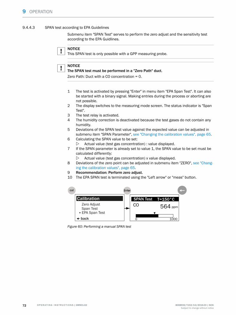
9.4.4.3 SPAN test according to EPA Guidelines
Submenu item "SPAN Test" serves to perform the zero adjust and the sensitivity testaccording to the EPA Guidlines.
NOTICEThis SPAN test is only possible with a GPP measuring probe.
NOTICEThe SPAN test must be performed in a "Zero Path" duct.Zero Path: Duct with a CO concentration = 0.
1 The test is activated by pressing "Enter" in menu item "EPA Span Test". It can alsobe started with a binary signal. Making entries during the process or aborting arenot possible.
2 The display switches to the measuring mode screen. The status indicator is "SpanTest".
3 The test relay is activated.4 The humidity correction is deactivated because the test gases do not contain any
humidity.5 Deviations of the SPAN test value against the expected value can be adjusted in
submenu item "SPAN Parameter", see "Changing the calibration values", page 65.6 Calculating the SPAN value to be set:
w Actual value (test gas concentration) : value displayed.7 If the SPAN parameter is already set to value 1, the SPAN value to be set must be
calculated differently:w Actual value (test gas concentration) x value displayed.
8 Deviations of the zero point can be adjusted in submenu item "ZERO", see "Chang‐ing the calibration values", page 65.
9 Recommendation: Perform zero adjust.10 The EPA SPAN test is terminated using the "Left arrow" or "meas" button.
back
CalibrationZero AdjustSpan TestEPA Span Test
cal
Measuring T=150 °CSPAN Test T=150°C
0 1000
CO 564 ppm
Figure 60: Performing a manual SPAN test
9 OPERATION
72 O P E R A T I N G I N S T R U C T I O N S | GM901-02 8008932/Y153/3-0/2016-03 | SICKSubject to change without notice

9.4.5 Service menu "Maint"
The service area has the following submenu items:
1 Restart the system : Reset System2 Set maintenance mode: Maint Mode3 Analog output test: Test Analog Out4 Relay test: Test Relay5 Reset parameters: Reset Parameter
Measuring T=150 °CMeasuring T=150°C
0 1000
CO 564ppm
Parameters
back
Reset SystemMaint Mode: No
Maintenance
Test Analog OutTest Relay
maint
Reset Parameter
Figure 61: Path from Measuring Screen to change parameters (example)
9.4.5.1 Measuring system restart
Submenu item "Reset System" serves to restart the system.
b Switch to the Service menu with "maint", see "Service menu "Maint"", page 73.
NOTE
• A restart cannot be interrupted or terminated.• The restart takes a few seconds.• An input is not possible.
Parameters
back
Reset SystemMaint Mode: No
Maintenance
Test Analog OutTest Relay
Parameters
back
Reset System
Start: Enter
Are you sure to start reset procedure ?
ParametersReset SystemReset SystemPlease wait !************
Measuring T=150 °CMeasuring T=150°C
0 1000
CO 564ppm
Figure 62: Restarting the system
9.4.5.2 Activating/deactivating maintenance mode
When maintenance mode is active, the output relay drops off and the analog outputholds the last value.
NOTESelect "Yes" and press "Enter" to activate maintenance mode.The "Service" LED is on as long as maintenance mode is activated.
OPERATION 9
8008932/Y153/3-0/2016-03 | SICK O P E R A T I N G I N S T R U C T I O N S | GM901-02 73Subject to change without notice

Parameters
back
Reset SystemMaint Mode: No
Maintenance
Test Analog OutTest Relay
maint
Parameters
back
Reset SystemMaint Mode: No Yes
Maintenance
Test Analog OutTest Relay
select
Parameters
back
Reset SystemMaint Mode: No Yes
Maintenance
Test Analog OutTest Relay
select
Figure 63: Activating/deactivating maintenance mode
9.4.5.3 Setting the test analog output
DANGERThe device switches to maintenance mode as soon as submenu item "Test Analog Out"is activated. The “Service” LED goes on. The device switches back to measuring modeas soon as the right arrow button for "back" is pressed in the submenu.
Submenu "Test Analog Out" serves to change the mA value for the analog output andthen check the value output.
NOTE
• Zero Point: see "Setting the signal: Live Zero", page 63.• Upper output value: see "Setting the signal: Upper output value", page 63.
Parameters
back
Reset SystemMaint Mode: No
Maintenance
Test Analog OutTest Relay
maint
Parameters
back
Test Analog Out
Channel 1 : 04.0 mA
edit: enter
Parameters
back select
Test Analog Out
Channel 1 : 04.0 mA
Parameters
back select
Test Analog Out
Channel 1 : 04.0 mA
Parameters
back
Test Analog Out
Channel 1 : 06.0 mA
edit: enter
2 xParameters
back
Test Analog Out
Channel 1 : 06.0 mA
edit: enter
Figure 64: Setting the analog value
9.4.5.4 Test relay
Submenu "Test Relay" serves to test relays 1, 2 and 3.
9 OPERATION
74 O P E R A T I N G I N S T R U C T I O N S | GM901-02 8008932/Y153/3-0/2016-03 | SICKSubject to change without notice

Parameters
back
Reset SystemMaint Mode: No
Maintenance
Test Analog OutTest Relay
maint
Parameters
back
Test RelayRelay 1 : Off
edit: enter
Parameters
back select
Test Relay
Relay 2 : OffRelay 3 : Off
Relay 1 : Off OnRelay 2 : OffRelay 3 : Off
+
Parameters
back
Test RelayRelay 1 : OnRelay 2 : OffRelay 3 : Off
edit: enter
Figure 65: Testing relays 1, 2 and 3
9.4.5.5 Reset Parameter
Submenu "Reset Parameter" serves to reset all parameters to the factory settings.
NOTEThe password is necessary to reset the parameters to the factory settings. The deviceswitches to maintenance mode. The “Service” LED lights up.
Parameters
back
Maint Mode: NoMaintenance
Test Analog OutTest Relay
maint
Parameters
back
Reset Parameter
selectReset Parameter
Password: 0000
1)Parameters
back
Reset Parameter
Start: Enter
Are you sure to start reset procedure ?
ParametersReset ParameterReset SystemPlease wait !
Figure 66: Resetting parameters to the factory settings
Entering the password, see "Entering the password", page 54.
NOTEFactory settings for parameters, see "Basic parameters set", page 43.
OPERATION 9
8008932/Y153/3-0/2016-03 | SICK O P E R A T I N G I N S T R U C T I O N S | GM901-02 75Subject to change without notice
10 Maintenance
10.1 Safety
Electricity
WARNINGEndangerment of electrical safety during installation and maintenance work when thepower supply is not switched off
b Before starting the work on the device, ensure the power supply can be switchedoff using a power disconnector switch/circuit breaker in accordance with DIN EN61010.
b Make sure the power disconnector switch is easily accessible.b An additional disconnecting device is mandatory when the power disconnector
switch cannot be accessed or only with difficulty after installation of the deviceconnection.
b The power supply may only be activated again after the end of the work or for testpurposes by personnel carrying out the work under consideration of valid safetyregulations.
Noxious gas
WARNINGHealth risk through contact with toxic gasesThe modules and devices contain enclosed potentially dangerous gases that canescape due to a defect or leak. Should a leak occur, the concentrations within theenclosed device can rise to 350 ppm.
■ CO : 10 ml max. total volume.
b Check the condition of the seals on the device regularly.b Only open the device when good ventilation is available, especially when a leak of
one of the device components is suspected.
When using a purge air unit
CAUTIONRisk of device damage when the purge air is switched off too soonIf the purge air is switched off when the SR-unit or the reflector is still in the gas duct,hot and contaminated gas can cause device damage.
b Do not switch the purge air unit off as long as the SR-unit or the reflector is still onthe gas duct.
CAUTIONRisk of device damage caused by switching off the purge air too soonIf the purge air is switched off when the SR-unit is still in the gas duct, hot and contami‐nated gas can cause device damage.
b Switch off the purge air unit only after removal of the SR-unit from the gas duct.
10 MAINTENANCE
76 O P E R A T I N G I N S T R U C T I O N S | GM901-02 8008932/Y153/3-0/2016-03 | SICKSubject to change without notice

CAUTIONRisk of device damage caused by switching off the purge air too soonIf the purge air is switched off when the measuring device is still in the gas duct, hotand contaminated gas can cause device damage.
b Do not switch the purge air unit off as long as the measuring device is still in thegas duct.
10.2 Preparatory work
NOTESome maintenance tasks will cause the measuring device to switch to malfunction
b Activate Maintenance mode before starting work, see "Activating/deactivatingmaintenance mode", page 73.
NOTEb Ensure good accessibility to the device in accordance with valid accident preven‐
tion regulations.b Provide suitable work platforms or pedestals.
NOTEA zero path must be available for zero adjust.
10.3 Visual inspection
Interval Visual inspection Remarks
Daily Check active malfunction andwarning messages.
Monthly Check ambient conditions.
Half-yearly Check measured values forplausibility.
Half-yearly Check device for damage. • Check all hose fittings for tight seat.
• Check the housings of the sender andreceiver of the evaluation unit formechanical damage.
• Check flanges and screw fittings for tightseat.
Half-yearly Check electrical connectionsand cables.
• Check all cables for damage. Pay atten‐tion to chafe marks and kinks on cableducts.
• Check all electric connections for free‐dom from corrosion and tight seat.
• Check grounding conductors are freefrom corrosion.
Table 10: Visual inspection
10.4 Maintenance plan
Table with Maintenance plan for users
Table with Maintenance plan for Service
MAINTENANCE 10
8008932/Y153/3-0/2016-03 | SICK O P E R A T I N G I N S T R U C T I O N S | GM901-02 77Subject to change without notice

10.4.1 Maintenance Table for sender/receiver unit
Interval Maintenance work Remarks
Half-yearly
Check device for damage and contamination. Clean the respective housings if contami‐nated.
Clean optical surfaces.
Exchange wearing parts as necessary.
Perform zero point check.
Check optical alignment.
Check condition of weatherproof cover whenused. Remove contamination.
Table 11: Maintenance intervals for sender/receiver unit
10.4.2 Maintenance Table for GPP measuring probe
Interval Maintenance work Remarks
Half-yearlyClean outer surfaces of measuring probe.
Clean optical surfaces.
As required
Exchange the sinter filter.
Exchange the heaters.
Exchange the optical parts.
Table 12: Maintenance intervals for GPP measuring probe
10.4.3 Maintenance Table for purge air unit
Interval Maintenance work Remarks
Application-dependent(see mainte‐nancerequest)
Exchange filter element. Part No. for filter element and task descrip‐tion, see Operating Instructions SLV4.
Check the hose and hose clamp.
Task description, see Operating InstructionsSLV4.
Exchange the purge air filter.
Check fan motor noise.
Check the purge air heater (optional).
Check the function of the filter and differen‐tial pressure sensor (optional).
Table 13: Maintenance intervals for purge air unit
10.4.4 Maintenance Table for GMP measuring probe
Interval Maintenance work Remarks
Half-yearlyClean outer surfaces of measuring probe.
Clean optical surfaces.
As required Exchange the optical parts.
Table 14: Maintenance intervals for GMP measuring probe
10.4.5 Final maintenance work
NOTERecord all maintenance work done in a Maintenance Manual.
10 MAINTENANCE
78 O P E R A T I N G I N S T R U C T I O N S | GM901-02 8008932/Y153/3-0/2016-03 | SICKSubject to change without notice

11 Troubleshooting
11.1 Warning messages
Message Possible causes Measures
Analog input tempera‐ture out of range
Input signal (0 ... 20 mA) of the tempera‐ture measurement is outside the config‐ured limits, the system continues runningwith the default temperature value.
Check the temperature sensor.
Check the cable connection.
Check the parameter settings: see "Setting the signal:Live Zero", page 63, see "Setting the signal: Upper out‐put value", page 63.
Temperature low, nohumidity correction
Measured gas temperature is so low that itis assumed the plant has been switchedoff. This means the cross-sensitivity cor‐rection for exhaust gas humidity is not per‐formed.
No measures required when the plant is switched off
Check the parameter settings: see "Setting the signal:Live Zero", page 63, see "Setting the signal: Upper out‐put value", page 63.
The switching point is at 70 °C or half the value of thedefault temperature depending on which value is lower.
Check the temperature sensor.
Sensor low signal Dust content too high (outside the calibra‐tion data from project planning).
Observe the ambient conditions in the technical data.
Fog formation.
Optical surfaces contaminated. Clean the optical interfaces.
Device disadjusted. Check device alignment.
Lamp defective. Check lamp, exchange when necessary.
Check for free light path through the duct.
If warning messages still occur after carrying out themeasures: New zero adjust.
Warming up The required operating temperature is notreached shortly after switching on. Dis‐played measured values could be outsidethe tolerance.
Observe warming up time of approx. 30 minutes.
Table 15: Warning messages in the Diagnosis menu
TROUBLESHOOTING 11
8008932/Y153/3-0/2016-03 | SICK O P E R A T I N G I N S T R U C T I O N S | GM901-02 79Subject to change without notice

11.2 Malfunction messages
Message Possible causes Measures
EEPROM Parameter Invalid parameter. Perform reset parameter: see "Reset Parameter",page 75.
Reconfigure.
New zero adjust.
Evaluation unit defective. Contact SICK Service.
Sensor communication Data communication between receiverunit and evaluation unit interrupted.
Check cable connection and correct seating of the plugconnector.
Further measures, see "Communication fault betweenevaluation unit and receiver", page 84.
Sensor amplifier hasreached maximumvalue
Erroneous device adjustment. Check device alignment, realign when necessary.
Optical surfaces contaminated. Clean the optical interfaces.
Light path interrupted. Check for free light path through the duct.
Sensor no signal Erroneous device adjustment. Check device alignment, realign when necessary.
Optical surfaces contaminated. Clean the optical interfaces.
Check for free light path through the duct.
Receiver unit defective. Exchange receiver unit.
IR source fault Infrared module defective. Check lamp plug connector.
Risk of burns! Lamp is very hot when in operation.
b Let the device cool down before checking.b Wear protective gloves.
Check sender/receiver unit, exchage when necessary.
Chopper fault Chopper in sender unit defective. Check lamp plug connector.
Risk of burns! Lamp is very hot when in operation.
b Let the device cool down before checking.b Wear protective gloves.
Check sender/receiver unit, exchange when necessary.
Device not ready, warm‐ing up
The required operational temperature isnot reached shortly after switching on.
Observe warming up time of approx. 30 minutes.
Device is not capable of measuring.
Motor fault Motor in receiver unit defective. Exchange receiver unit.
Table 16: Malfunction message for Diagnosis menu
11 TROUBLESHOOTING
80 O P E R A T I N G I N S T R U C T I O N S | GM901-02 8008932/Y153/3-0/2016-03 | SICKSubject to change without notice

11.3 Troubleshooting on the sender
1
6
5
43
7
89
ß
2
à
Figure 67: Sender
1 IR source: Plug connection2 IR source
Risk of burns!The infrared lamp becomes extremely hot during operation!
3 Adjustment screws: 4 x
Disadjustment through adjusting the adjustment screws!Readjustment is only possible at the factory
4 Chopper motor plug5 Internal plug6 External plug7 Receiver cable8 LED: On when voltage connected for motor and logic module9 LED: On when voltage for IR source connectedß LED: On when the lamp is on and the chopper disk rotatesà Sender housing
TROUBLESHOOTING 11
8008932/Y153/3-0/2016-03 | SICK O P E R A T I N G I N S T R U C T I O N S | GM901-02 81Subject to change without notice

11.4 Troubleshooting on receiver
1
á
à
6
5
4
3
2
7
8
9
ß
Figure 68: Receiver
1 LED: On when operation is uninterrupted2 LED as status indicator for optics heating:
• On continuously: Ambient temperature too high
• Blinks: Normal operation
• Off: Ambient temperature too low3 LED: Communication to evaluation unit (TD)4 LED: Communication from evaluation unit (RD)5 LED: Blinks when the cell disk in the receiver rotates and receives chopper signal.6 LED: Blinks when the motor of the cell disk rotates7 Line to sender8 Outer plug-in connector9 Inner plug-in connectorß Line to evaluation unità Adjustment screws: 4 x
Disadjustment through adjusting the adjustment screws!Readjustment is only possible at the factory.
á Receiver housing
11 TROUBLESHOOTING
82 O P E R A T I N G I N S T R U C T I O N S | GM901-02 8008932/Y153/3-0/2016-03 | SICKSubject to change without notice

11.5 Troubleshooting on the evaluation unit
-+Sensor -+ -+
Fuse 2,5 AT250 V
PE N L1
40..60 Hz
Serv
ice
RS23
2
230Vor115V
100
CAN
GN
D
CAN
-HG
ND
+24V
CAN
-L
Contrast
1
6
54
8
9ß
2
3
7
à
Figure 69: Sender
1 Data to receiver (TD)2 Data from receiver (RD)3 Digital input status indicator4 Analog output status indicator: LED on when output power is the same as the setpoint value5 Relay 1 switching state6 Relay 2 switching state7 Receiver connection8 Fuses, 2.5 AT9 LED: On when 24 V power supply presentß LED: On when 5 V power supply for internal logic presentà Operating voltage selection
Check
Check voltage supply
Check fuses in evaluation unit
Check indicator for 24 V /5 V supply in evaluation unit. To do this, disconnect the cable to thereceiver
If the indicators are only on when the plug-in connector is disconnected, check the cabling ofthe components. Observe the following sequence when connecting:
1 Cable from evaluation unit -> receiver2 Receiver3 Cable from receiver -> sender4 Sender
If the fault occurs, it is caused by the last component connected. Exchange this compo‐nent
Table 17: Checks when the device shows no reaction
TROUBLESHOOTING 11
8008932/Y153/3-0/2016-03 | SICK O P E R A T I N G I N S T R U C T I O N S | GM901-02 83Subject to change without notice

11.6 Communication fault between evaluation unit and receiver
Error message: "Sensor Communication"
The receiver sends a constant stream of data to the evaluation unit; if this is notreceived, an error message is output automatically.
Check following connections:
1 Evaluation unit -> receiver.2 Cable connection on the plug-in terminal in the evaluation unit.3 Cable to receiver.4 Outer plug-in connector on receiver.5 Inner plug-in connector in receiver.
11.6.1 Sensor values for trouble-free operation
All values refer to a warmed up device in operation withing the specific limits.
Calling up the sensor values: see "Viewing sensor values", page 56.
Unit Description Min.value
Typical value Max.value
V1 Signal voltage 1 0.5 V Depending on the current condi‐tions
<5.0
V2 Signal voltage 2 0.5 V Depending on the current condi‐tions
<5.0
DK Variation k-value 0 Depending on the current condi‐tions
CC Peltier current 0 mA Dependent on the ambient tem‐perature
1200 mA
TE Temperature electronics 20°C Dependent on the ambient tem‐perature
80 °C
TO Temperatur optics 50 °C 60 °C 80 °C
TD Detector temperature 9 °C 10.7 °C 12 °C
A Amplifier setting 00.00 Dependent on the measuringpath
31.31
Table 18: Sensor values
NOTEPlease contact SICK Service for remote diagnosis should the sensor values of theGM901-02 be outside these value ranges.
b Use the form, see "Remote Diagnosis, GM901 Sensor Values", page 85.
11 TROUBLESHOOTING
84 O P E R A T I N G I N S T R U C T I O N S | GM901-02 8008932/Y153/3-0/2016-03 | SICKSubject to change without notice

11.6.2 Remote Diagnosis, GM901 Sensor Values
Company: Date:
Contact person: Plant:
Email: Telefon:
Malfunction messagesMalfunction message 1: ___________________Malfunction message 2: ___________________Warning messagesWarning message 1: ___________________Warning message 2: ___________________Sensor valuesV1: __________________ CC:____________________ TD: ____________________V2:__________________ TE:____________________ AG:____________________DK: __________________ TO:____________________Parameters■ Physical Unit: ___________________■ Normalization: ___________________■ Response time: ___________________■ Measuring range:■ Measuring distance Fl.-Fl.: ______________ Active:______________■ Temperature Substitute: ______________ External: ______________
Scale Low: ______________ Scale High:______________Scale High: ______________ Input High: ______________
■ Humidity Substitute: ______________■ Pressure Substitute: ______________■ Analog Out: Active Zero: ______________■ Calibration SPAN: ______________ Zero: ______________
Device■ Serial Number: ___________________■ Software Revision Sensor Unit: ______________ Evaluation Unit: ______________■ Configuration No: ______________Service C1: ______________ C2: ______________
C3: ______________ C4: ______________C5: ______________ C6: ______________C7: ______________ C8: ______________
Current measuring conditionsMeasured value: ______________Exhaust gas temperature: ______________Ambient temperature: _______________
TROUBLESHOOTING 11
8008932/Y153/3-0/2016-03 | SICK O P E R A T I N G I N S T R U C T I O N S | GM901-02 85Subject to change without notice
11.7 Measures after purge air failure (when using the GMP measuring probe)
Failure of the purge air supply can cause the following damage:
• Damage/destruction of the sender/receiver unit through hot and corrosive gas.• With overpressure, gas can penetrate the purge air compressor and filter via the
purge air hose and damage these system parts.
Measures:
1 Open the quick-release fasteners on the sender/receiver unit and remove thedevice.
2 As protective measure, especially with overpressure, close off the flange openingwith heat-resistant material (blind flange, optional).
3 Clear the failure cause (see Operating Instructions for purge air supply) orexchange the purge air supply.
4 Connect the purge air supply.5 Refit the units and switch on again.
11 TROUBLESHOOTING
86 O P E R A T I N G I N S T R U C T I O N S | GM901-02 8008932/Y153/3-0/2016-03 | SICKSubject to change without notice
12 Decommissioning
12.1 Safety information on shutting down
DANGERHealth risk though pressure and hot or toxic gasesDangerous pressures, hot or toxic gases can escape when opening the duct dependingon the process gas characteristics.
b Before installing the sender, receiver and measuring probe, be sure to take allsafety measures that prevent gas escaping uncontrolled.
DANGERRisk to health through contaminated measuring deviceToxic residues may be present in acidic process gas on the measuring device afteroperation.
b Always wear the specified protective clothing.
DANGERRisk to health through contaminated measuring probeDepending on the composition of the gas in the measuring channel, the measuringprobe could be contaminated with substances which could result in serious healthdamage.
b Decontaminate the measuring probe before storage.b Wear the specified protective clothing for all work with a contaminated measuring
probe.
DECOMMISSIONING 12
8008932/Y153/3-0/2016-03 | SICK O P E R A T I N G I N S T R U C T I O N S | GM901-02 87Subject to change without notice

12.2 Materials and tools required
Materials and tools required Required for
Insulated screwdriver set Electrical connections
TORX screwdriver, size 10 GPP probe
Allen key Connections
19 mm open-ended spanner or ring spanner Flange screw fitting
2 x 24 mm open-ended spanners or ring spanners
Cleaning cloths Cleaning the housing
Personal protective equipment Protection when working on thestack
Flange cover Closing off the stack
SICK original transport safeguards and packaging Storing the measuring device
Table 19: Materials and tools required for shutting down
12.3 Disassembling the sender and receiver
Disassembling the measuring device is recommended for longer plant standstills.
NOTEThe analyzer must be removed from the gas duct when:
■ The optional purge air unit is taken out of operation on device versions with GMPmeasuring probe.
■ The heating is no longer in operation on device versions with GPP measuringprobe.
Procedure
1 Disconnect the device from the power supply.2 Disconnect the cable plug on the sender/receiver unit. For longer storage: Protect
the cable plug against damp and dirt.3 Take the sender and receiver off the T-piece:
w Undo the quick-release fastenersw Take the sender or receiver off
4 Remove the probe.5 Close off the opening on the T-piece with an optional blind flange.
NOTEThe optical adjustment remains intact.
12 DECOMMISSIONING
88 O P E R A T I N G I N S T R U C T I O N S | GM901-02 8008932/Y153/3-0/2016-03 | SICKSubject to change without notice

12.4 Storage
WARNINGRisk of chemical burns/poisoning through caustic/toxic residues on components withsample gas contactAfter the device has been shutdown or removed from the measuring duct, process gasresidues can deposit on components with sample gas contact (e.g., measuring probe,gas filter, gas-carrying lines etc.). These residues can be odorless or invisible dependingon the gas mixture in the duct. Without protective clothing, contact with such contami‐nated components can lead to severe burns or poisoning.
b Take appropriate protective measures for work (e.g., by wearing a safety mask,protective gloves and acid resistant clothes).
b In case of contact with skin or the eyes, rinse immediately with clear water andconsult a doctor.
b Decontaminate all contaminated components according to regulations after disas‐sembly.
1 Clean the outside of all housings, the measuring probe and all other componentswith slightly moistened cleaning cloths. A mild cleaning agent can be used.
2 Protect the openings on the SR-unit and measuring probe against atmosphericconditions. Refit transport safeguards.
3 Pack the device for storage or transport (preferably in the original packing).4 Store the device and all belonging components in a dry, clean room.
12.5 Disposal
The device can easily be disassembled into its components which can then be sent tothe respective raw material recycling facilities.
NOTEThe following subassemblies contain substances that may have to be disposed of sepa‐rately:
• Electronics: Capacitors, rechargeable batteries, batteries.• Display: Liquid of LC display.• Sample gas filter and measuring probe could be contaminated by pollutants.
w Decontaminate the measuring probe and filter before disposal.
DECOMMISSIONING 12
8008932/Y153/3-0/2016-03 | SICK O P E R A T I N G I N S T R U C T I O N S | GM901-02 89Subject to change without notice
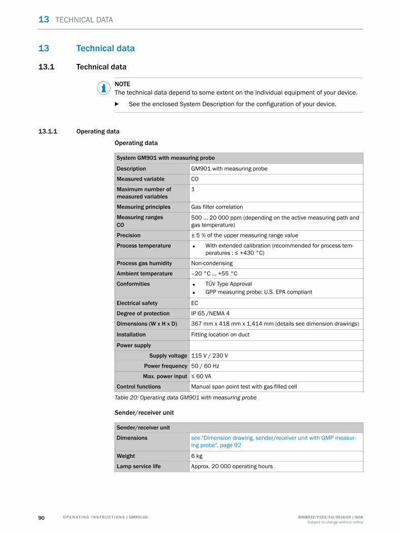
13 Technical data
13.1 Technical data
NOTEThe technical data depend to some extent on the individual equipment of your device.
b See the enclosed System Description for the configuration of your device.
13.1.1 Operating data
Operating data
System GM901 with measuring probe
Description GM901 with measuring probe
Measured variable CO
Maximum number ofmeasured variables
1
Measuring principles Gas filter correlation
Measuring rangesCO
500 ... 20 000 ppm (depending on the active measuring path andgas temperature)
Precision ± 5 % of the upper measuring range value
Process temperature • With extended calibration (recommended for process tem‐peratures : ≤ +430 °C)
Process gas humidity Non-condensing
Ambient temperature –20 °C ... +55 °C
Conformities • TÜV Type Approval
• GPP measuring probe: U.S. EPA compliant
Electrical safety EC
Degree of protection IP 65 /NEMA 4
Dimensions (W x H x D) 367 mm x 418 mm x 1,414 mm (details see dimension drawings)
Installation Fitting location on duct
Power supply
Supply voltage 115 V / 230 V
Power frequency 50 / 60 Hz
Max. power input ≤ 60 VA
Control functions Manual span point test with gas-filled cell
Table 20: Operating data GM901 with measuring probe
Sender/receiver unit
Sender/receiver unit
Dimensions see "Dimension drawing, sender/receiver unit with GMP measur‐ing probe", page 92
Weight 6 kg
Lamp service life Approx. 20 000 operating hours
13 TECHNICAL DATA
90 O P E R A T I N G I N S T R U C T I O N S | GM901-02 8008932/Y153/3-0/2016-03 | SICKSubject to change without notice
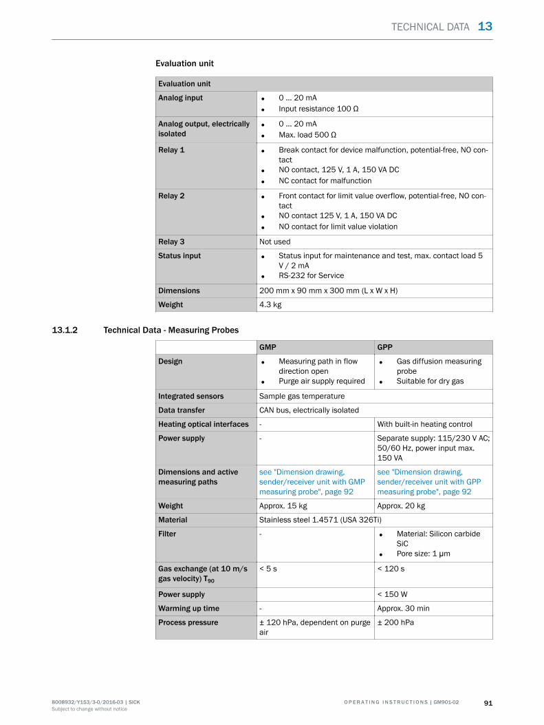
Evaluation unit
Evaluation unit
Analog input • 0 ... 20 mA
• Input resistance 100 Ω
Analog output, electricallyisolated
• 0 ... 20 mA
• Max. load 500 Ω
Relay 1 • Break contact for device malfunction, potential-free, NO con‐tact
• NO contact, 125 V, 1 A, 150 VA DC
• NC contact for malfunction
Relay 2 • Front contact for limit value overflow, potential-free, NO con‐tact
• NO contact 125 V, 1 A, 150 VA DC
• NO contact for limit value violation
Relay 3 Not used
Status input • Status input for maintenance and test, max. contact load 5V / 2 mA
• RS-232 for Service
Dimensions 200 mm x 90 mm x 300 mm (L x W x H)
Weight 4.3 kg
13.1.2 Technical Data - Measuring Probes
GMP GPP
Design • Measuring path in flowdirection open
• Purge air supply required
• Gas diffusion measuringprobe
• Suitable for dry gas
Integrated sensors Sample gas temperature
Data transfer CAN bus, electrically isolated
Heating optical interfaces - With built-in heating control
Power supply - Separate supply: 115/230 V AC;50/60 Hz, power input max.150 VA
Dimensions and activemeasuring paths
see "Dimension drawing,sender/receiver unit with GMPmeasuring probe", page 92
see "Dimension drawing,sender/receiver unit with GPPmeasuring probe", page 92
Weight Approx. 15 kg Approx. 20 kg
Material Stainless steel 1.4571 (USA 326Ti)
Filter - • Material: Silicon carbideSiC
• Pore size: 1 μm
Gas exchange (at 10 m/sgas velocity) T90
< 5 s < 120 s
Power supply < 150 W
Warming up time - Approx. 30 min
Process pressure ± 120 hPa, dependent on purgeair
± 200 hPa
TECHNICAL DATA 13
8008932/Y153/3-0/2016-03 | SICK O P E R A T I N G I N S T R U C T I O N S | GM901-02 91Subject to change without notice
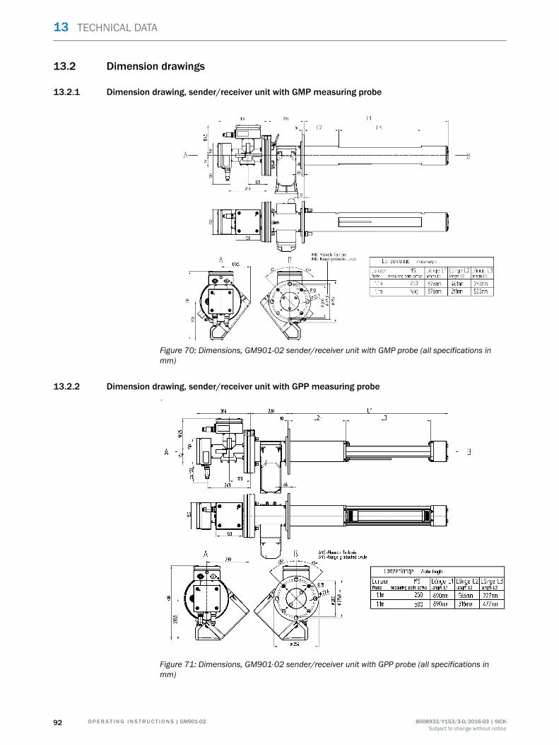
13.2 Dimension drawings
13.2.1 Dimension drawing, sender/receiver unit with GMP measuring probe
Figure 70: Dimensions, GM901-02 sender/receiver unit with GMP probe (all specifications inmm)
13.2.2 Dimension drawing, sender/receiver unit with GPP measuring probe
Figure 71: Dimensions, GM901-02 sender/receiver unit with GPP probe (all specifications inmm)
13 TECHNICAL DATA
92 O P E R A T I N G I N S T R U C T I O N S | GM901-02 8008932/Y153/3-0/2016-03 | SICKSubject to change without notice
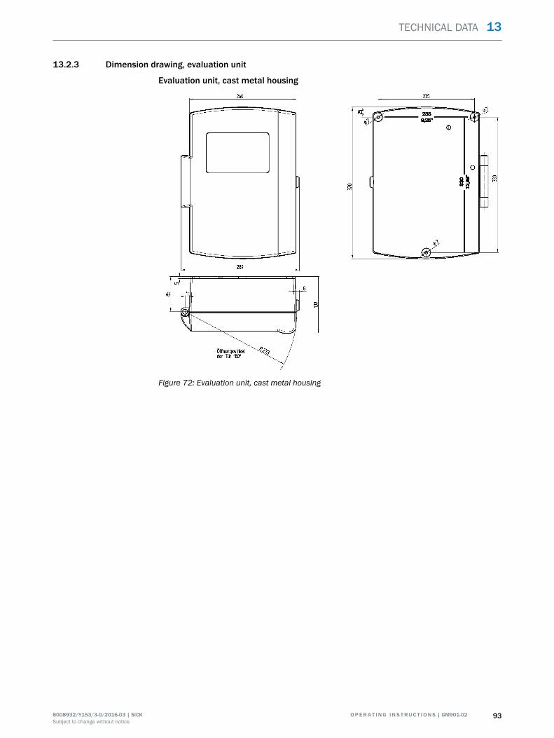
13.2.3 Dimension drawing, evaluation unit
Evaluation unit, cast metal housing
Figure 72: Evaluation unit, cast metal housing
TECHNICAL DATA 13
8008932/Y153/3-0/2016-03 | SICK O P E R A T I N G I N S T R U C T I O N S | GM901-02 93Subject to change without notice

13.2.4 Dimension drawings, accessories
13.2.4.1 Dimension drawing, purge air unit
Figure 73: Dimensions, evaluation unit (all specifications in mm)
13 TECHNICAL DATA
94 O P E R A T I N G I N S T R U C T I O N S | GM901-02 8008932/Y153/3-0/2016-03 | SICKSubject to change without notice

13.2.4.2 Dimension drawing, terminal box
PG11
PG13.5
52
1136
125
14
8023
57
∅ 5
Figure 74: Dimensions, terminal box (all specifications in mm)
13.2.4.3 Weatherproof cover
Weatherproof cover for sender/receiver unit
576,3525,825,2
507,
829
7
240
636,4
Figure 75: Weatherproof cover for sender/receiver unit
TECHNICAL DATA 13
8008932/Y153/3-0/2016-03 | SICK O P E R A T I N G I N S T R U C T I O N S | GM901-02 95Subject to change without notice

14 Ordering information
14.1 Spare parts
Designation Quan‐tity
Part No.
Sender GM901 without purge air fixture 1 2019650
Receiver GM901 without purge air fixture 1 2019651
Evaluation unit GM901 1 1052190
Receiver connection cable 1 2020447
Connection cable, length 15 m 1 2020439
Membrane keyboard, evaluation unit GM901 1 6020400
PT1000/20 m converter 1 6021161
Table 21: Spare parts numbers
14.2 Accessories
Designation Quan‐tity
Part No.
Optical adjustment device 1 2020436
Purge air unit with distributor and 5 m hose (only for GMP measur‐ing probe)
1 1012424
Purge air hose Permeter
5304683
Connection unit with power supply 230 V / 24 V for sender andreceiver
1 2020440
Weatherproof cover for purge air unit 1 5306108
Weatherproof cover for GM901 sender / receiver 2 2702407
Weatherproof cover for GM901 evaluation unit 1 4029146
Operating Instructions, English 1 8008250
Filter element 1 5306091
Test case for SPAN test with holder and up to 3 cells 1 2019639
Table 22: Accessory part numbers
14 ORDERING INFORMATION
96 O P E R A T I N G I N S T R U C T I O N S | GM901-02 8008932/Y153/3-0/2016-03 | SICKSubject to change without notice

15 List of tables
1. Warning symbols...........................................................................................................62. Information symbols..................................................................................................... 73. Product identification................................................................................................. 114. GM901-02 layout........................................................................................................125. GMP and GPP measuring probes in comparison..................................................... 156. Installation steps overview.........................................................................................227. Material required for commissioning........................................................................ 358. Overview of commissioning steps............................................................................. 369. Significance of LEDs...................................................................................................5110. Visual inspection.........................................................................................................7711. Maintenance intervals for sender/receiver unit.......................................................7812. Maintenance intervals for GPP measuring probe.....................................................7813. Maintenance intervals for purge air unit...................................................................7814. Maintenance intervals for GMP measuring probe....................................................7815. Warning messages in the Diagnosis menu...............................................................7916. Malfunction message for Diagnosis menu............................................................... 8017. Checks when the device shows no reaction............................................................. 8318. Sensor values............................................................................................................. 8419. Materials and tools required for shutting down........................................................8820. Operating data GM901 with measuring probe.........................................................9021. Spare parts numbers................................................................................................. 9622. Accessory part numbers............................................................................................ 96
LIST OF TABLES 15
8008932/Y153/3-0/2016-03 | SICK O P E R A T I N G I N S T R U C T I O N S | GM901-02 97Subject to change without notice

More representatives and agencies
at www.sick.com
Australia
Phone +61 3 9457 0600
1800 334 802 – tollfree
E-Mail [email protected]
Austria
Phone +43 (0)22 36 62 28 8-0
E-Mail [email protected]
Belgium/Luxembourg
Phone +32 (0)2 466 55 66
E-Mail [email protected]
Brazil
Phone +55 11 3215-4900
E-Mail [email protected]
Canada
Phone +1 905 771 14 44
E-Mail [email protected]
Czech Republic
Phone +420 2 57 91 18 50
E-Mail [email protected]
Chile
Phone +56 2 2274 7430
E-Mail [email protected]
China
Phone +86 4000 121 000
E-Mail [email protected]
Denmark
Phone +45 45 82 64 00
E-Mail [email protected]
Finland
Phone +358-9-2515 800
E-Mail [email protected]
France
Phone +33 1 64 62 35 00
E-Mail [email protected]
Gemany
Phone +49 211 5301-301
E-Mail [email protected]
Great Britain
Phone +44 (0)1727 831121
E-Mail [email protected]
Hong Kong
Phone +852 2153 6300
E-Mail [email protected]
Hungary
Phone +36 1 371 2680
E-Mail [email protected]
India
Phone +91–22–4033 8333
E-Mail [email protected]
Israel
Phone +972-4-6881000
E-Mail [email protected]
Italy
Phone +39 02 27 43 41
E-Mail [email protected]
Japan
Phone +81 (0)3 5309 2112
E-Mail [email protected]
Malaysia
Phone +603 808070425
E-Mail [email protected]
Netherlands
Phone +31 (0)30 229 25 44
E-Mail [email protected]
New Zealand
Phone +64 9 415 0459
0800 222 278 – tollfree
E-Mail [email protected]
Norway
Phone +47 67 81 50 00
E-Mail [email protected]
Poland
Phone +48 22 837 40 50
E-Mail [email protected]
Romania
Phone +40 356 171 120
E-Mail [email protected]
Russia
Phone +7-495-775-05-30
E-Mail [email protected]
Singapore
Phone +65 6744 3732
E-Mail [email protected]
Slovakia
Phone +421 482 901201
E-Mail [email protected]
Slovenia
Phone +386 (0)1-47 69 990
E-Mail [email protected]
South Africa
Phone +27 11 472 3733
E-Mail [email protected]
South Korea
Phone +82 2 786 6321
E-Mail [email protected]
Spain
Phone +34 93 480 31 00
E-Mail [email protected]
Sweden
Phone +46 10 110 10 00
E-Mail [email protected]
Switzerland
Phone +41 41 619 29 39
E-Mail [email protected]
Taiwan
Phone +886 2 2375-6288
E-Mail [email protected]
Thailand
Phone +66 2645 0009
E-Mail [email protected]
Turkey
Phone +90 (216) 528 50 00
E-Mail [email protected]
United Arab Emirates
Phone +971 (0) 4 88 65 878
E-Mail [email protected]
USA/Mexico
Phone +1(952) 941-6780
1 (800) 325-7425 – tollfree
E-Mail [email protected]
Vietnam
Phone +84 8 62920204
E-Mail [email protected]
SICK AG | Waldkirch | Germany | www.sick.com
8008
932/
Y153
/201
6-03


