12
Operating instructions Grip fork FC Danger Read the entire operating manual before using the front loader. 3 54 26 80 P 1524 EN

Operating instructions
Grip fork FC
D a n g e r Read the entire operating manual before using the front loader.
3 54 26 80 P 1524 EN
2
Table of contents Operation in accordance with specifications ........................................ 3 Safety technical advices....................................................................... 4 Description ........................................................................................... 6 Before the first operating ...................................................................... 6 Setting to work...................................................................................... 7 Parking of implement............................................................................ 7 Service and maintenance..................................................................... 8 Warranty............................................................................................... 9 EC-Declaration of conformity ............................................................... 11 Noise information Noise emission value measured at the operators position....70 dB(A)
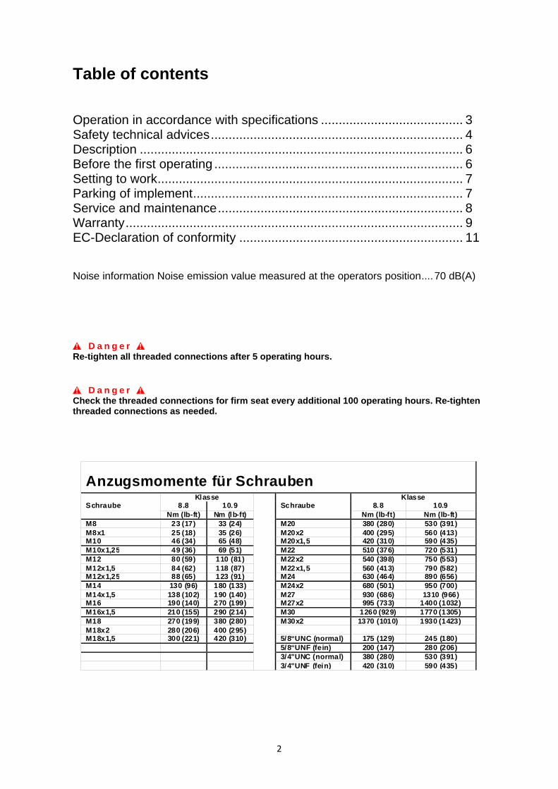
D a n g e r Re-tighten all threaded connections after 5 operating hours.
D a n g e r Check the threaded connections for firm seat every additional 100 operating hours. Re-tighten threaded connections as needed.
Anzugsmomente für Schrauben Schraube
Klasse
Schraube Klasse
8.8 10.9 8.8 10.9 Nm (lb-ft) Nm (lb-ft) Nm (lb-ft) Nm (lb-ft)
M8 23 (17) 33 (24) M20 380 (280) 530 (391) M8x1 25 (18) 35 (26) M20x2 400 (295) 560 (413) M10 46 (34) 65 (48) M20x1,5 420 (310) 590 (435) M10x1,25 49 (36) 69 (51) M22 510 (376) 720 (531) M12 80 (59) 110 (81) M22x2 540 (398) 750 (553) M12x1,5 84 (62) 118 (87) M22x1,5 560 (413) 790 (582) M12x1,25 88 (65) 123 (91) M24 630 (464) 890 (656) M14 130 (96) 180 (133) M24x2 680 (501) 950 (700) M14x1,5 138 (102) 190 (140) M27 930 (686) 1310 (966) M16 190 (140) 270 (199) M27x2 995 (733) 1400 (1032)M16x1,5 210 (155) 290 (214) M30 1260 (929) 1770 (1305)M18 270 (199) 380 (280) M30x2 1370 (1010) 1930 (1423)M18x2 280 (206) 400 (295) M18x1,5 300 (221) 420 (310) 5/8“UNC (normal) 175 (129) 245 (180) 5/8“UNF (fein) 200 (147) 280 (206) 3/4"UNC (normal) 380 (280) 530 (391) 3/4"UNF (fein) 420 (310) 590 (435)
3
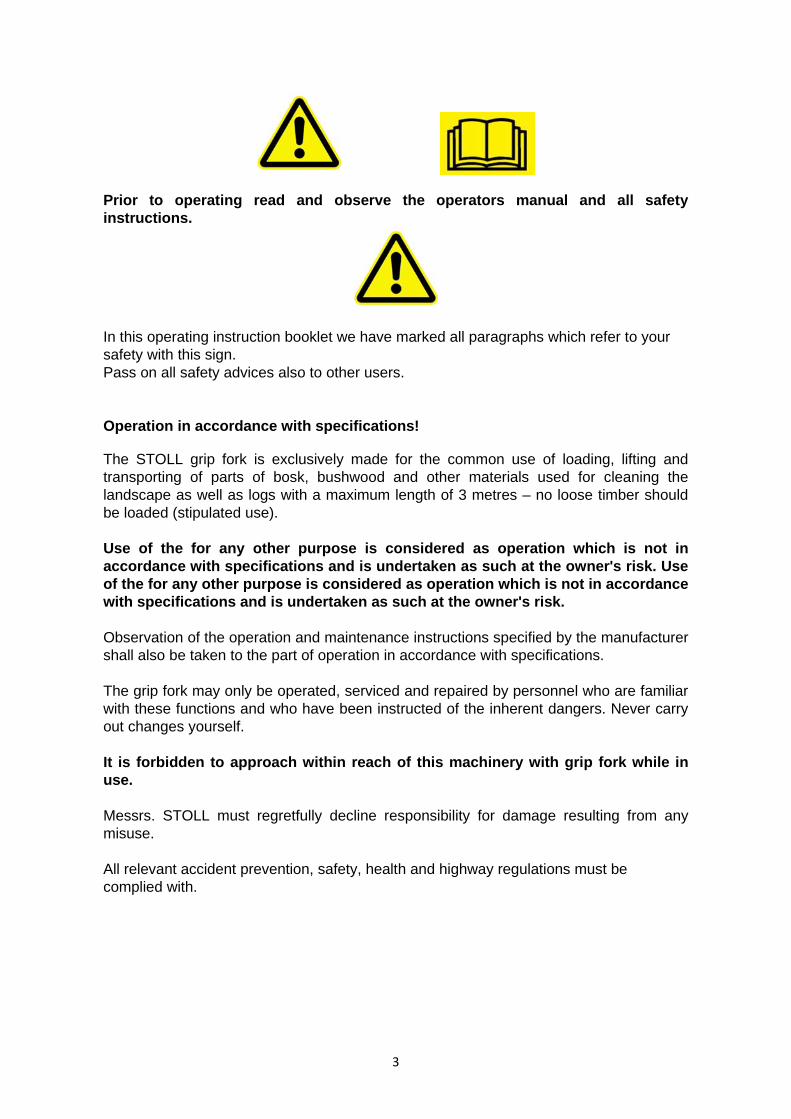
Prior to operating read and observe the operators manual and all safety instructions.
In this operating instruction booklet we have marked all paragraphs which refer to your safety with this sign. Pass on all safety advices also to other users. Operation in accordance with specifications!
The STOLL grip fork is exclusively made for the common use of loading, lifting and transporting of parts of bosk, bushwood and other materials used for cleaning the landscape as well as logs with a maximum length of 3 metres – no loose timber should be loaded (stipulated use). Use of the for any other purpose is considered as operation which is not in accordance with specifications and is undertaken as such at the owner's risk. Use of the for any other purpose is considered as operation which is not in accordance with specifications and is undertaken as such at the owner's risk. Observation of the operation and maintenance instructions specified by the manufacturer shall also be taken to the part of operation in accordance with specifications. The grip fork may only be operated, serviced and repaired by personnel who are familiar with these functions and who have been instructed of the inherent dangers. Never carry out changes yourself. It is forbidden to approach within reach of this machinery with grip fork while in use. Messrs. STOLL must regretfully decline responsibility for damage resulting from any misuse. All relevant accident prevention, safety, health and highway regulations must be complied with.
4
Safety and prevention of accidents Most accidents which occur in agricultural enterprises are the result of safety rules being disregarded by personnel.
1. Aquaint yourself with all equipments and control elements just as their function before work start. During work it is too late for that.
2. Before any operation of the grip fork put the hydr. control unit to its neutral position.
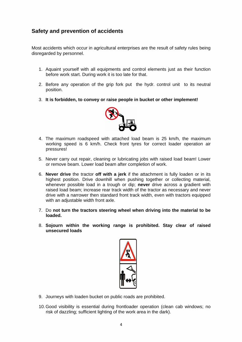
3. It is forbidden, to convey or raise people in bucket or other implement!
4. The maximum roadspeed with attached load beam is 25 km/h, the maximum working speed is 6 km/h. Check front tyres for correct loader operation air pressures!
5. Never carry out repair, cleaning or lubricating jobs with raised load beam! Lower or remove beam. Lower load beam after completion of work.
6. Never drive the tractor off with a jerk if the attachment is fully loaden or in its highest position. Drive downhill when pushing together or collecting material, whenever possible load in a trough or dip; never drive across a gradient with raised load beam; increase rear track width of the tractor as necessary and never drive with a narrower then standard front track width, even with tractors equipped with an adjustable width front axle.
7. Do not turn the tractors steering wheel when driving into the material to be loaded.
8. Sojourn within the working range is prohibited. Stay clear of raised unsecured loads
9. Journeys with loaden bucket on public roads are prohibited.
10. Good visibility is essential during frontloader operation (clean cab windows; no risk of dazzling; sufficient lighting of the work area in the dark).

5
11. Ensure that the front loader is a safe distance away from overhead power lines. Danger to life in case of contact.
12. Liquids leaking under high pressure (Diesel fuel, hydraulic oil) can penetrate the skin and cause severe injury. When injured see a doctor immediately! Danger of infection!
13. Before the first use of the bucket with grab and then at least once a year all hoses must be checked by an expert worker for their operational safety and replaced if required. The time of use of the hoses should not exceed six years including a maximum storage time of two years. The replacement hoses and pipings must meet with the implement manufacturer's technical standards.
14. When searching for leaks appropriate aids should be used because of the danger of injury.
15. Moreover, the accident prevention rules of agricultural trade associations and application requirements for protective devices according to the machinery protection act and the rules of trafic act have to be observed.

6
Description
The STOLL grip fork consists of a fork, hydraulic connections for the quick-fit frame and a double-acting hydraulic cylinder which operates the upper grip of the implement.
For the operation of the double-acting hydraulic cylinder of the tines of the upper grip, the tractor – respectively the loader – needs to be equipped with a 3rd oil circuit or a double-acting additional control valve.
The STOLL grip fork will be used mainly for loading of timber, bushwood and other materials used for cleaning the landscape. Even loading of logs with a maximum length of 3 metres is possible. You may not use the grip fork for loading of loose timber as the loose parts may clamp between the tines and could result in bending the complete fork.
By means of the long tines of the upper grab, you may easily load and transport big volumes of bushwood and unload it well-dosed.
Before the first operating
The STOLL grip fork is readily mounted factory-side. You only need to connect the two hydraulic connections of the cylinder which are closed with plastic caps. Corresponding tubes are included in a separate bag. Connect all parts correspondingly before the first operation.
First, the two plastic caps need to be removed at the hydraulic cylinder and the screw-in fitting will be fixed tightly. After this, the 2 hydraulic tubes (shown on the picture) need to be fixed with the screw-in fitting and will be connected on the other side with the coupling muff. The coupling muff which supplies the lower side of the cylinder, gets the red closing cap and the other side the black one .Finally, we recommend bundling the individual tubes by means of a cable clip.
7
Setting to work
1. Attachment to the frontloader beam − Please go with the quick-fit frame under the plates of the implement and tilt and lift
the quick-fit frame slightly. Then swing the locking hook of the quick-fit frame into the openings of the implement. ATTENTION: Locking lever needs to be moved to the final catch to ensure a full interlocking (see manual of the loader).
2. Hydraulic connection
− Connect the hydraulic hoses with the couplings to the connections of the 3rd control circuit.
3. The tines of the upper gripper may not be bent in order to ensure proper work.
Replace or align immediately tines which might be bent. 4. Operation
− With the grip fork in horizontal position, fully open the top grab. − Grip fork with opened tines upper grab needs to be pierced into the material. − Please swing down the upper grab as far as possible – using middle-size speed
drive .You need to pay attention to the fact that the tines of the upper grab could go deeper than the lower part of the fork tines. This may result in damages of the ground or similar. To prevent this, please lift the implement slightly before closing the upper tines.
− After lifting of the loading goods with the loader, the tines of the upper grab need to be closed again to ensure that loose material will be fixed for the transport. ATTENTION. Drive carefully!
Parking of implements
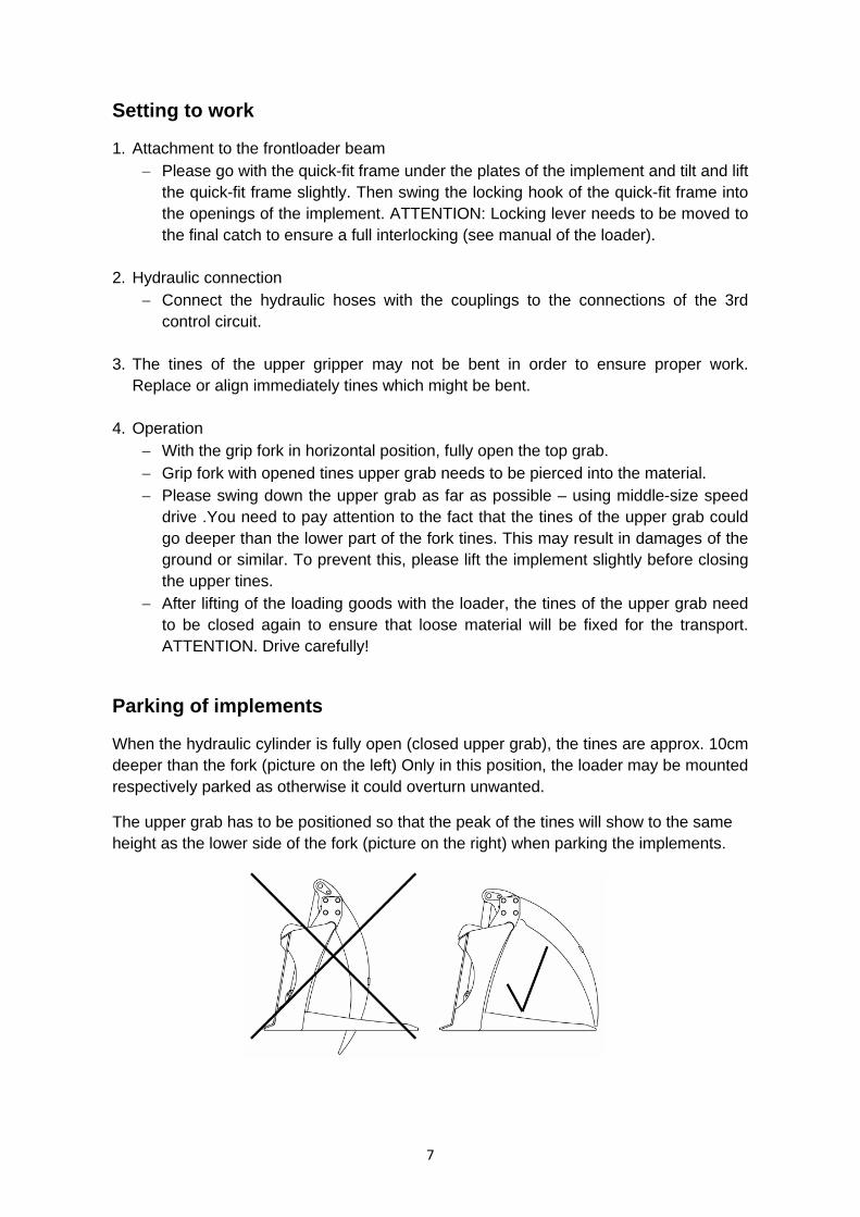
When the hydraulic cylinder is fully open (closed upper grab), the tines are approx. 10cm deeper than the fork (picture on the left) Only in this position, the loader may be mounted respectively parked as otherwise it could overturn unwanted.
The upper grab has to be positioned so that the peak of the tines will show to the same height as the lower side of the fork (picture on the right) when parking the implements.

8
Care and maintenance
The instructions and guidelines published by the tractor manufacturers apply to the service and maintenance of the hydraulic system.
Grease bearings and swivel parts of the grip fork all 10 operating hours.
Swivel bearing of the movable top grab 2 lubrcation points Hydrocylinder-bearing 2 lubrication points
For frontloader operation it is recommendable to use a ballast weight at the rear hydraulic linkage at tractors with 4-wheel drive.
Tighten all screwed joints periodical! Use only original STOLL-spare parts!
9
Terms of Warranty
When taking delivery of the STOLL grip fork check immediately that all items ordered have been included. Have any claim confirmed by the forwarding agent on the delivery note and inform the supplier within 14 days about the deficiency (for the extent of supply refer to the “list of items supplied”).
We substitute any material which proves to be defective, within the warranty period (six months starting on the day of delivery), provided that the liability to pay assumed at the moment of delivery is met at the terms fixed.
Warranty involves at the supplier’s discretion either the repair of the defective component or its replacement (carriage ex works or stock). Any claims which go beyond the replacement of parts (e.g. loss or operational failure) are rejected explicitly.
Warranty becomes null and void if the implement was modified by installation of foreign components without our knowledge and agreement, especially if improper modifications have been carried out.
Warranty becomes likewise null and void if an ascertained defect has not been repaired immediately in a proper way. Repairs of defects caused by operational influences suppose our previous agreement if the total or partial restitution of expenses is claimed.
No warranty is granted for any damage to the grip fork caused by the non-observance of the permissible working capacity or transport speed. Wear and tear and damage caused by negligent or improper use of the implement as well as defects resulting from storage and corrosion are not subject to warranty.
Components not manufactured by Stoll (hydraulics) are subject to the terms of warranty laid down by the respective manufacturers.
Bucket components which a warranty claim is raised for, have immediately to be sent to our works (Broistedt station) or one of our stocks for material test or ascertainment of damage. Components which are substituted by new ones, become our property.
Furthermore, the standard terms of warranty are applicable for the STOLL grip fork.

10
Notice
11
Wilhelm STOLL Maschinenfabrik GmbH
Postfach 11 81 D-38266 Lengede Bahnhofstr. 21 D-38268 Lengede Telefon: +49 / (0) 53 44 / 20 0 Telefax: +49 / (0) 53 44 / 20 182 E-Mail: [email protected] Internet: www.stoll-jf.de
P1524_EN11RE01.PDF
Dealer address


![2015 / 16...Southampton FC Stoke City FC Sunderland AFC Swansea City AFC Tottenham Hotspur FC [London ] Watford FC West Bromwich Albion FC West Ham United FC [London ] …](https://static.documents.pub/doc/80x56/6147d88ca830d0442101b33e/2015-16-southampton-fc-stoke-city-fc-sunderland-afc-swansea-city-afc-tottenham.jpg)

