40
OPERATING INSTRUCTIONS
OPERATING INSTRUCTIONS
BOSCH– 2 –ST–VS/PMV
Table of Contents
OPERATING INSTRUCTIONS Bosch Videosystem ViStar 2.04.998.142.245 A1
Introduction and safety instructions 3. . . . . . . . . . . . . . . . . . .
Main screen 4. . . . . . . . . . . . . . . . . . . . . . . . . . . . . . . . . . . . . . . . . Logging on / logging off the system 4Standby screen 6Main menu 7
Message processing 10. . . . . . . . . . . . . . . . . . . . . . . . . . . . . . . . Incoming messages and their processing 10
Navigation 13. . . . . . . . . . . . . . . . . . . . . . . . . . . . . . . . . . . . . . . . . . Graphical navigation 13Address and location overviews 18
Image recall 19. . . . . . . . . . . . . . . . . . . . . . . . . . . . . . . . . . . . . . . . Requesting archive images 19Requesting camera images 21
Image archive viewer for swapped–out images 22. . . . . . . .
Image archive backup viewer 23. . . . . . . . . . . . . . . . . . . . . . . .
Logging 24. . . . . . . . . . . . . . . . . . . . . . . . . . . . . . . . . . . . . . . . . . . . Statistics 24
Faults and alarms 25. . . . . . . . . . . . . . . . . . . . . . . . . . . . . . . . . . . System messages 25
Image data backup on a medium 27. . . . . . . . . . . . . . . . . . . . . Swapping out images 27
Hard disk transport for systems with removable disks. 28General 28Access to image data 29
Central user workstation: access to subsystem 30. . . . . . . Change of the subsystem 30
Define operating times 31Time programs 31
Send e–mail and SMS to a target person 35
Appendix: CD–ROM 36. . . . . . . . . . . . . . . . . . . . . . . . . . . . . . . . . Formatting a CD–R and copying data 36
BOSCH– 3 –ST–VS/PMV
Introduction and safety instructions
The device may only be operated by trained persons. For securityreasons and in order to avoid faulty operation, any authorizationcode required for operation should only be communicated tothese persons.
What do these operating instructions tell you?In these instructions you will find information that you need for theoperation of the video system. Please see also the detailed onlinehelp.
What don’t these operating instructions tell you?These operating instructions provide no information about generalor specific security–technical knowledge. Therefore, please make sure that you are familiar with all security–technical procedures and regulations in your area (e.g. deploymentplans, occupation plans, etc.).
When cleaning the surface, especially the operating and displayunit, please ensure that no caustic or scrubbing cleansers are usedand that no liquid can penetrate the insides of the device.Also follow the individual manufacturer’s instructions.
Central service station
TelephoneStatus: October 2002
BOSCH– 4 –ST–VS/PMV
Main screen
Logging on / logging off the system
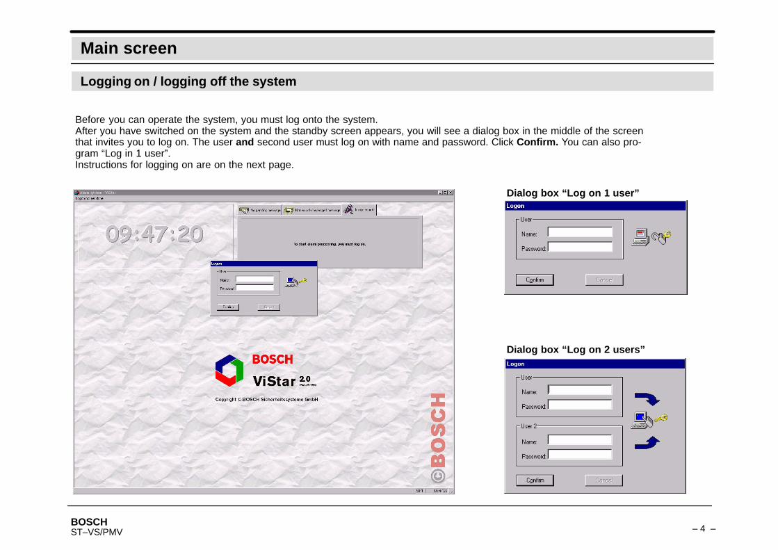
Before you can operate the system, you must log onto the system.After you have switched on the system and the standby screen appears, you will see a dialog box in the middle of the screenthat invites you to log on. The user and second user must log on with name and password. Click Confirm. You can also pro-gram “Log in 1 user”.Instructions for logging on are on the next page.
Dialog box “Log on 2 users”
Dialog box “Log on 1 user”

BOSCH– 5 –ST–VS/PMV
Main screen
Logging on / logging off the system
Logging on with name and passwordThe principle of dual control applies; that is, no user, not even an administrator or technician, but only certain people can log in alone.Regardless of the authorization level,the first user must first log on correctly, then a second user must log on. This second login will only be permitted if– the second user has the same authorization level and– he is not the same as the first user.– Optionally, he must belong to another user group.Both logins are logged. For further operational actions, however, the first user counts as logged on; the second has only activated him.If “Log on 1 user” is programmed, then “Name and Password” are sufficient.
Validity periodThe validity period of the user can be set. If it has expired, you must reprogram the data for the user.The validity period of passwords can be set.If the validity period for the (correctly entered) password has expired on login, the user will be required to enter a new password twice (thispassword must be different than the old one). This password is newly programmed for the same time period.
Loggingoff
PasswordPasswords must be at least 8 characters long (lower–case and capital letters, numbers, and representable special characters).
From the main menu, select System and click Log off user.
Note:You can only log off if all messages have been acknowledged.
BOSCH– 6 –ST–VS/PMV
Main screen
Standby screen
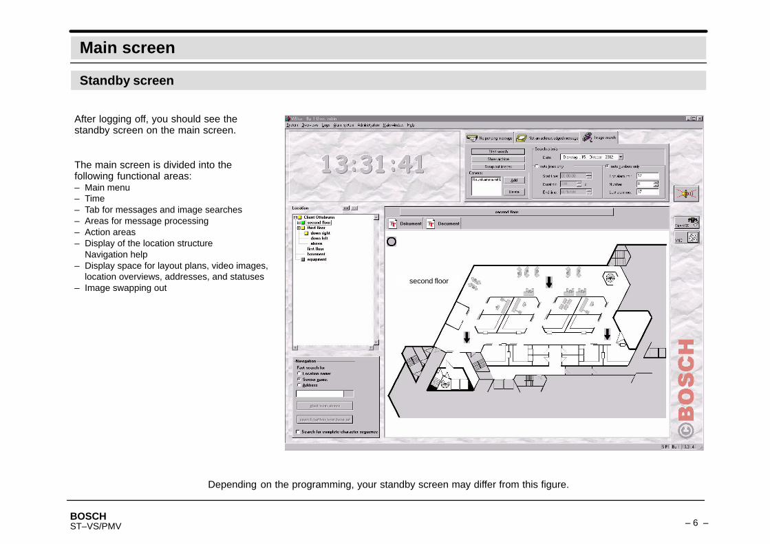
Depending on the programming, your standby screen may differ from this figure.
After logging off, you should see thestandby screen on the main screen.
The main screen is divided into thefollowing functional areas:– Main menu– Time– Tab for messages and image searches– Areas for message processing– Action areas– Display of the location structure
Navigation help– Display space for layout plans, video images,
location overviews, addresses, and statuses– Image swapping out
second floor
BOSCH– 7 –ST–VS/PMV
Main screen
Main menu
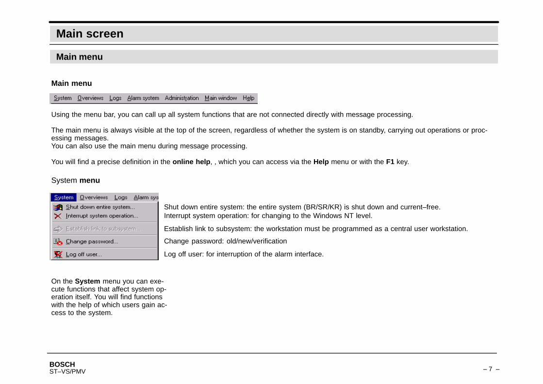
Using the menu bar, you can call up all system functions that are not connected directly with message processing.
The main menu is always visible at the top of the screen, regardless of whether the system is on standby, carrying out operations or proc-essing messages.You can also use the main menu during message processing.
You will find a precise definition in the online help, , which you can access via the Help menu or with the F1 key.
Main menu
System menu
On the System menu you can exe-cute functions that affect system op-eration itself. You will find functionswith the help of which users gain ac-cess to the system.
Change password: old/new/verification
Log off user: for interruption of the alarm interface.
Shut down entire system: the entire system (BR/SR/KR) is shut down and current–free.Interrupt system operation: for changing to the Windows NT level.
Establish link to subsystem: the workstation must be programmed as a central user workstation.
BOSCH– 8 –ST–VS/PMV
Main screen
Main menu
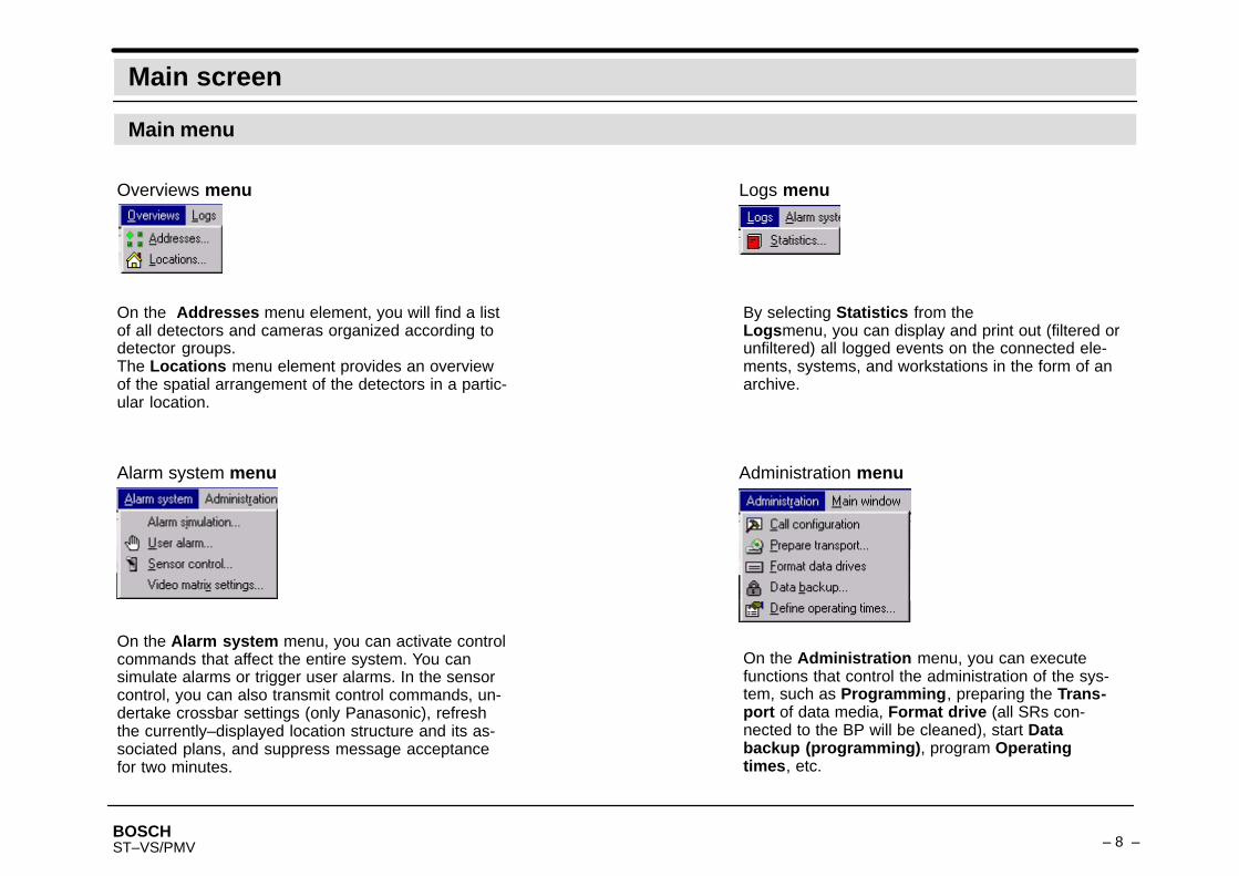
Overviews menu
On the Addresses menu element, you will find a listof all detectors and cameras organized according todetector groups.The Locations menu element provides an overviewof the spatial arrangement of the detectors in a partic-ular location.
Logs menu
Alarm system menu Administration menu
By selecting Statistics from theLogsmenu, you can display and print out (filtered orunfiltered) all logged events on the connected ele-ments, systems, and workstations in the form of anarchive.
On the Alarm system menu, you can activate controlcommands that affect the entire system. You cansimulate alarms or trigger user alarms. In the sensorcontrol, you can also transmit control commands, un-dertake crossbar settings (only Panasonic), refreshthe currently–displayed location structure and its as-sociated plans, and suppress message acceptancefor two minutes.
On the Administration menu, you can executefunctions that control the administration of the sys-tem, such as Programming, preparing the Trans-port of data media, Format drive (all SRs con-nected to the BP will be cleaned), start Databackup (programming), program Operatingtimes, etc.
BOSCH– 9 –ST–VS/PMV
Main screen
Main menu
Main window menu Help menu
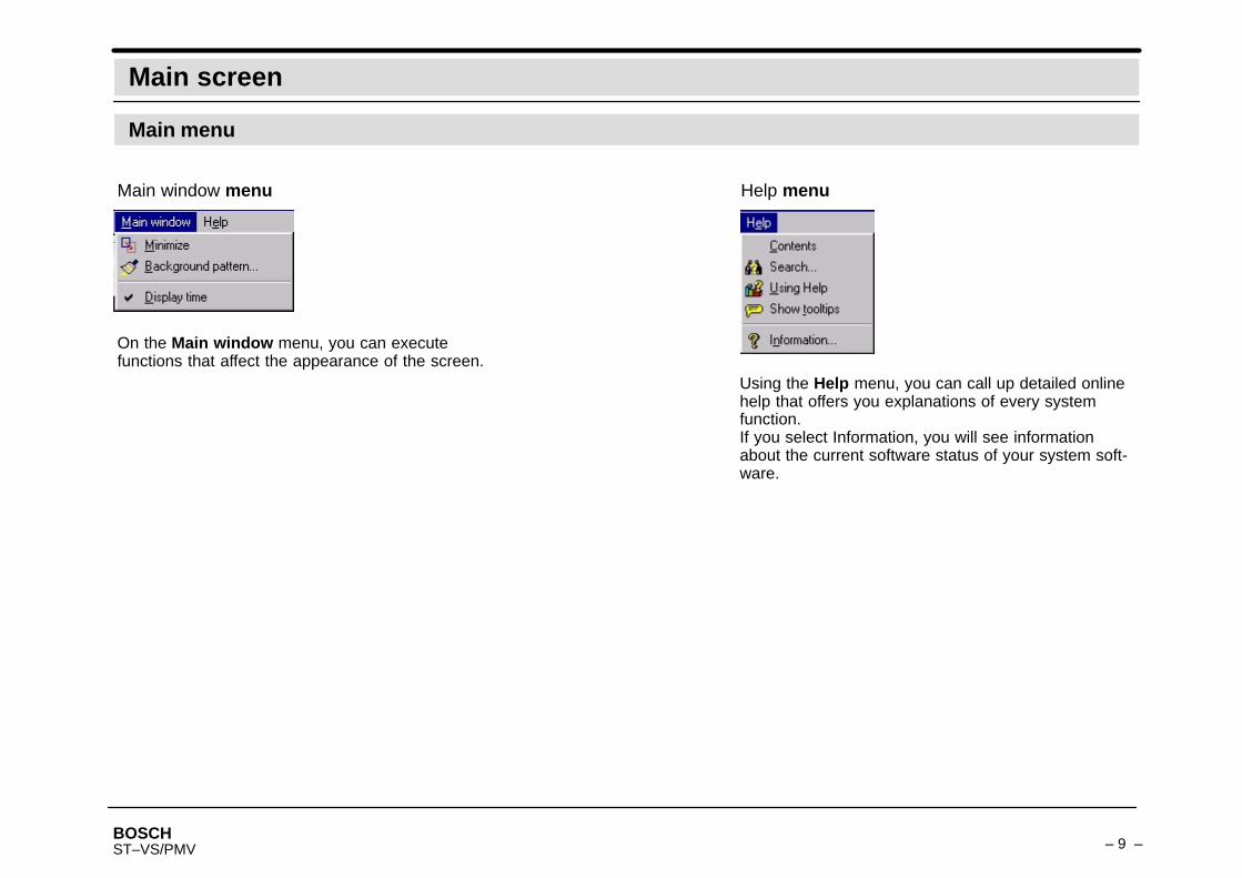
On the Main window menu, you can executefunctions that affect the appearance of the screen.
Using the Help menu, you can call up detailed onlinehelp that offers you explanations of every systemfunction.If you select Information, you will see informationabout the current software status of your system soft-ware.
BOSCH– 10 –ST–VS/PMV
Message processing
Incoming messages and their processing
Typical flow of a message process (movement in the image)
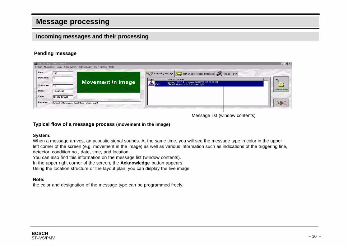
System:When a message arrives, an acoustic signal sounds. At the same time, you will see the message type in color in the upperleft corner of the screen (e.g. movement in the image) as well as various information such as indications of the triggering line,detector, condition no., date, time, and location.You can also find this information on the message list (window contents).In the upper right corner of the screen, the Acknowledge button appears.Using the location structure or the layout plan, you can display the live image.
Note:the color and designation of the message type can be programmed freely.
Pending message
Message list (window contents)
BOSCH– 11 –ST–VS/PMV
Message processing
Incoming messages and their processing
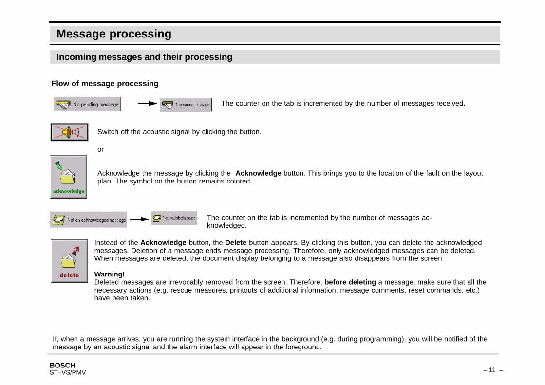
Switch off the acoustic signal by clicking the button.
Acknowledge the message by clicking the Acknowledge button. This brings you to the location of the fault on the layoutplan. The symbol on the button remains colored.
or
Flow of message processing
The counter on the tab is incremented by the number of messages ac-knowledged.
Instead of the Acknowledge button, the Delete button appears. By clicking this button, you can delete the acknowledgedmessages. Deletion of a message ends message processing. Therefore, only acknowledged messages can be deleted.When messages are deleted, the document display belonging to a message also disappears from the screen.
Warning!Deleted messages are irrevocably removed from the screen. Therefore, before deleting a message, make sure that all thenecessary actions (e.g. rescue measures, printouts of additional information, message comments, reset commands, etc.)have been taken.
The counter on the tab is incremented by the number of messages received.
If, when a message arrives, you are running the system interface in the background (e.g. during programming), you will be notified of themessage by an acoustic signal and the alarm interface will appear in the foreground.

BOSCH– 12 –ST–VS/PMV
Message processing
Incoming messages and their processing
Action buttons (optional)
If they are programmed, you will see the Action buttons on the right edge of the screen below this button. Each button isassociated with a command or command sequence. These can be activated with a click of the button. Depending on theprogramming, the buttons may be visible during the entire operation, they may appear only under certain circumstances(e.g. during message processing) or only on the standby screen.
End of message processing
Message processing ends if the tabs for Pending and Acknowledged messageseach show none.
Deleting specific messagesSelect the message that you want to delete from the message list. The message list for acknowledged messages appears on the screen ifyou click on the Acknowledged message tab.
Click the Delete button to delete the selected message.
Inadvertent deletion of messagesIf you inadvertently delete an acknowledged message (e.g. before a specific message document is printed or a measure initiated), this mes-sage can no longer be displayed onscreen.
However, you do have the opportunity to reconstruct information about these messages.– Via its statistics
From the main menu, select Logs and then the Statistics menu element.
BOSCH– 13 –ST–VS/PMV
Navigation
Graphical navigation
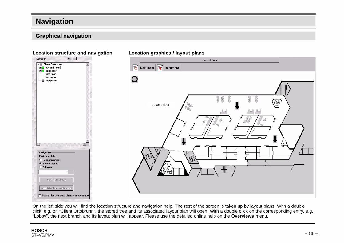
On the left side you will find the location structure and navigation help. The rest of the screen is taken up by layout plans. With a doubleclick, e.g. on “Client Ottobrunn”, the stored tree and its associated layout plan will open. With a double click on the corresponding entry, e.g.“Lobby”, the next branch and its layout plan will appear. Please use the detailed online help on the Overviews menu.
Location structure and navigation Location graphics / layout plans
second floor

BOSCH– 14 –ST–VS/PMV
Navigation
Graphical navigation
Location structure
Using an example, here is an explanation of how to work in the location structure, navigation in layout plans, finding cameras,etc. The starting point of the location structure is “Client Ottobrunn”.
Location structure Associated location graphic
With a double click of the left mouse button on “Client Ottobrunn”, the location structure will open.For each subpoint, e.g. “second floor” that you double click with the left mouse button, you will see the corresponding layout planappear. See next page.
For quick opening and closingof the entire location structure.
BOSCH– 15 –ST–VS/PMV
Navigation
Graphical navigation
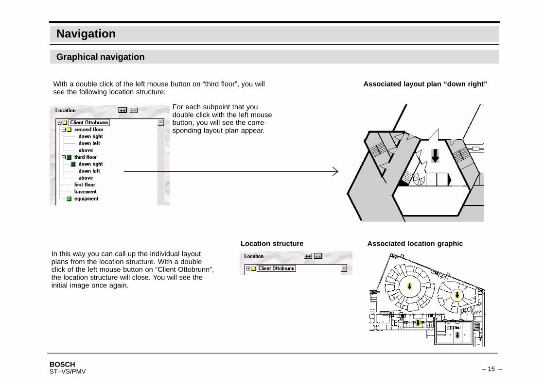
With a double click of the left mouse button on “third floor”, you willsee the following location structure:
For each subpoint that youdouble click with the left mousebutton, you will see the corre-sponding layout plan appear.
Associated layout plan “down right”
In this way you can call up the individual layoutplans from the location structure. With a doubleclick of the left mouse button on “Client Ottobrunn”,the location structure will close. You will see theinitial image once again.
Location structure Associated location graphic
BOSCH– 16 –ST–VS/PMV
Navigation
Graphical navigation
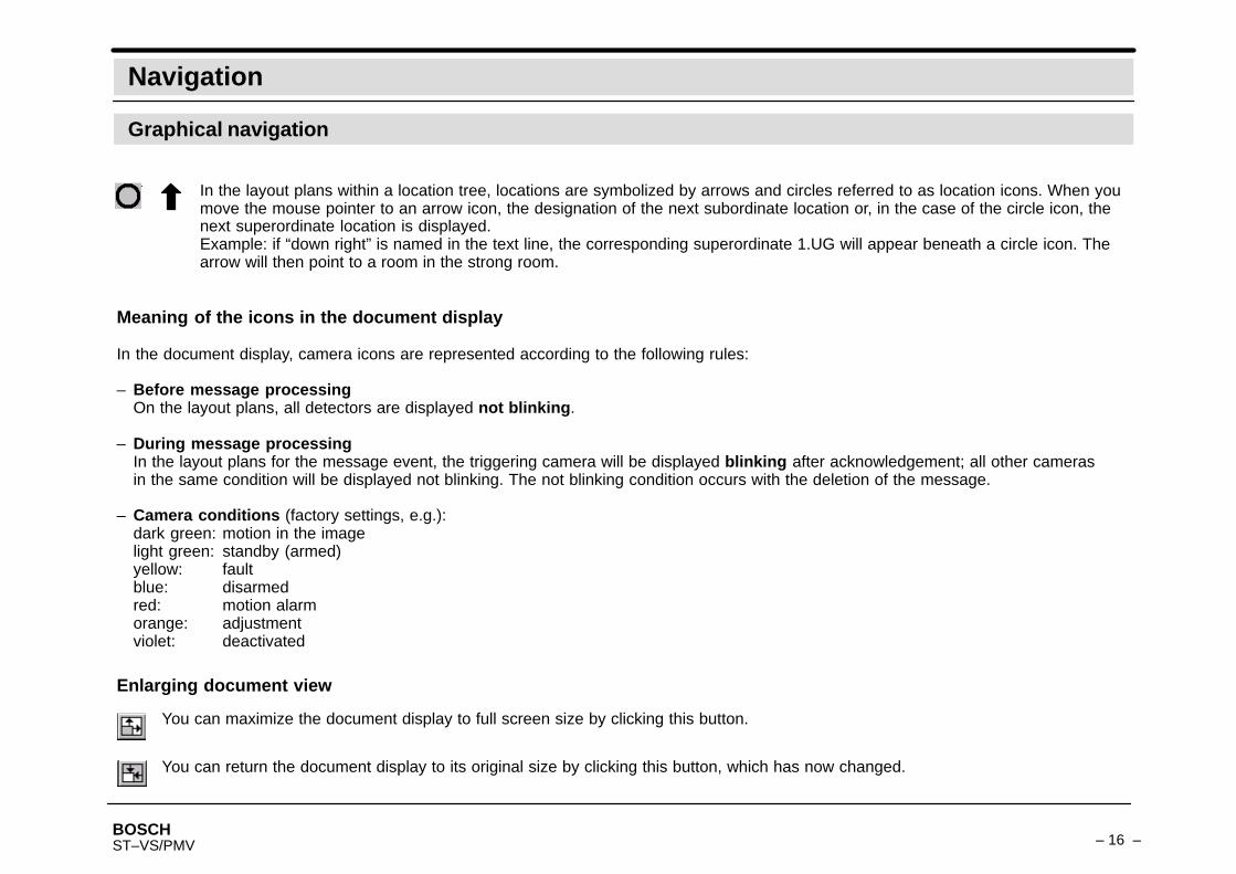
Meaning of the icons in the document display
In the document display, camera icons are represented according to the following rules:
– Before message processingOn the layout plans, all detectors are displayed not blinking.
– During message processingIn the layout plans for the message event, the triggering camera will be displayed blinking after acknowledgement; all other cameras in the same condition will be displayed not blinking. The not blinking condition occurs with the deletion of the message.
– Camera conditions (factory settings, e.g.):dark green: motion in the imagelight green: standby (armed)yellow: faultblue: disarmedred: motion alarmorange: adjustmentviolet: deactivated
In the layout plans within a location tree, locations are symbolized by arrows and circles referred to as location icons. When youmove the mouse pointer to an arrow icon, the designation of the next subordinate location or, in the case of the circle icon, thenext superordinate location is displayed.Example: if “down right” is named in the text line, the corresponding superordinate 1.UG will appear beneath a circle icon. Thearrow will then point to a room in the strong room.
Enlarging document view
You can maximize the document display to full screen size by clicking this button.
You can return the document display to its original size by clicking this button, which has now changed.

BOSCH– 17 –ST–VS/PMV
Navigation
Graphical navigation
In the Navigation dialog box, you can call up layout plans using the location name, sensor name, or cor-responding address. Click the corresponding button, enter the name as the location name (e.g. “down) andclick the Begin from above buttonThe jump from the location structure “Client...” to “down...” is executed immediately. You will see the layoutplan “down right”.If from here you want to search for additional subtitles, click the Search again from here on button. Addi-tional subtitles and the associated layout plans on the topic “down right” will be displayed.This search procedure also applies to sensor names and addresses.
With Video sensor live image, you can make the live image appear. (Only for programmed live imagecameras).Note: the menu contents depend on the programming and your authorization.
With Image on monitor (parallel), you can choose to display the image or standby image on the video moni-tor.With Video sensor sensitivity, you can arm or disarm the cameras after adjustment. (project–specific)With Video sensor condition, you can switch the video sensor on or off.With Camera settings, you can change the camera settings.
Only activate if you want the entire sequence, e.g. down right.
With Add to search, you can add the camera in question to the image search.With New search, the image search will be started.
By clicking a mouse button on a camera drawn in on the location structure, the following menuwill appear.
BOSCH– 18 –ST–VS/PMV
Navigation
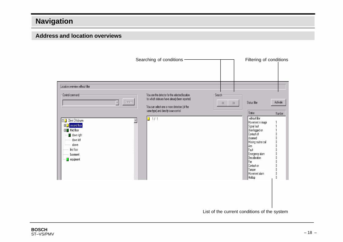
Address and location overviews
Searching of conditions Filtering of conditions
List of the current conditions of the system
BOSCH– 19 –ST–VS/PMV
Image recall
Requesting archive images
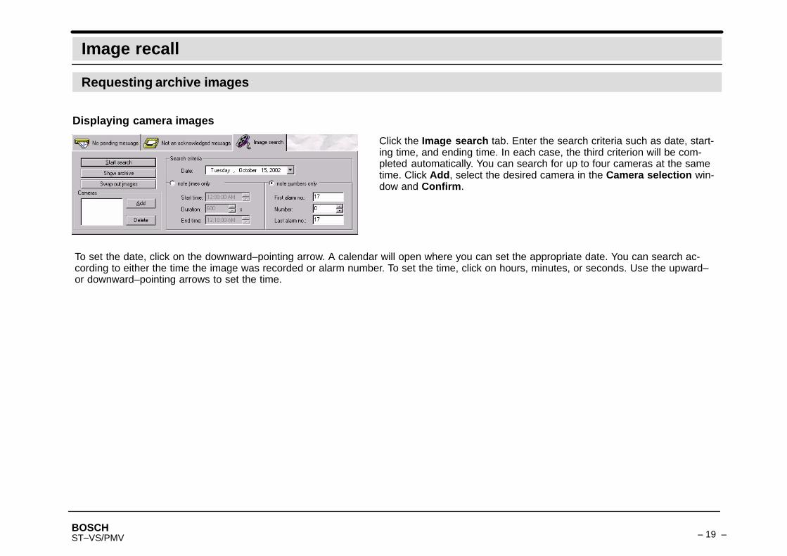
Displaying camera images
Click the Image search tab. Enter the search criteria such as date, start-ing time, and ending time. In each case, the third criterion will be com-pleted automatically. You can search for up to four cameras at the sametime. Click Add, select the desired camera in the Camera selection win-dow and Confirm.
To set the date, click on the downward–pointing arrow. A calendar will open where you can set the appropriate date. You can search ac-cording to either the time the image was recorded or alarm number. To set the time, click on hours, minutes, or seconds. Use the upward–or downward–pointing arrows to set the time.

BOSCH– 20 –ST–VS/PMV
Image recall
Requesting archive images
Example: a camera image
Menu bar
Back to the layout plan
Displaying/hidingthe archive list
With this buttonyou can cancel/force the alignment.
Cutfrom ISDN or networkto an outstation
Operating bar
Image settinglarge/small
Connect

BOSCH– 21 –ST–VS/PMV
Image recall
Requesting camera images
Example: three camera images (max. 8) im-ages
Archive list:thus it is possible toselect an image di-rectly.
Activating the bar/list
Date and timewhen recording ofthis image cluster of30MB began.
Icon bar
Status bar
BOSCH– 22 –ST–VS/PMV
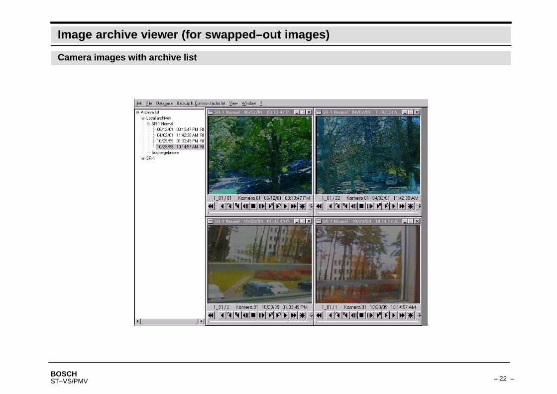
Image archive viewer (for swapped–out images)
Camera images with archive list

BOSCH– 23 –ST–VS/PMV
Image archive backup viewer
Note:You can also zoom individual images. Click the left mouse button on the image and its size will be doubled. You can do this several times.Clicking the right mouse button will switch off the zoom.
If you click Start search , you will see the camera images with the Backup viewer.At the lower edge and on the right side of the requested camera image, you will find buttons. If you hold the mousepointer over the buttons, you will see the associated function.
Film stop
First image
Slowly backwards
Real time backwards
Playback backwards
Previous image
Next image Replay forwards
Real time forwardsSlowly forwards
Last image
Synchronous unspooling of films
Selection of the film; image retained during further search (max. 8).Is otherwise closed.
Example see next page
Save
green light:image is in the search area
red light:image is not in the search area
Image archive / backup viewer

BOSCH– 24 –ST–VS/PMV
Logging
Statistics
All system–related events (if programmed) will be logged in a long–term record (statistics).Network failure will be displayed on the NZ 500 (optional) as “Fault network ” and signaled acoustically (buzzer).
Please use the online help
Every system station records its own Statistics, which depending on settings, are either stored for max. 30 days or max.12 months.After the set time has been exceeded, the oldest entry (a day/month) will be deleted for new entries.You can filter, display, and print out the statistical data according to any criteria.By double clicking on an individual entry or clicking “Show details ” you can call up additional information.
Individual entry
Statistics
BOSCH– 25 –ST–VS/PMV
Faults and alarms
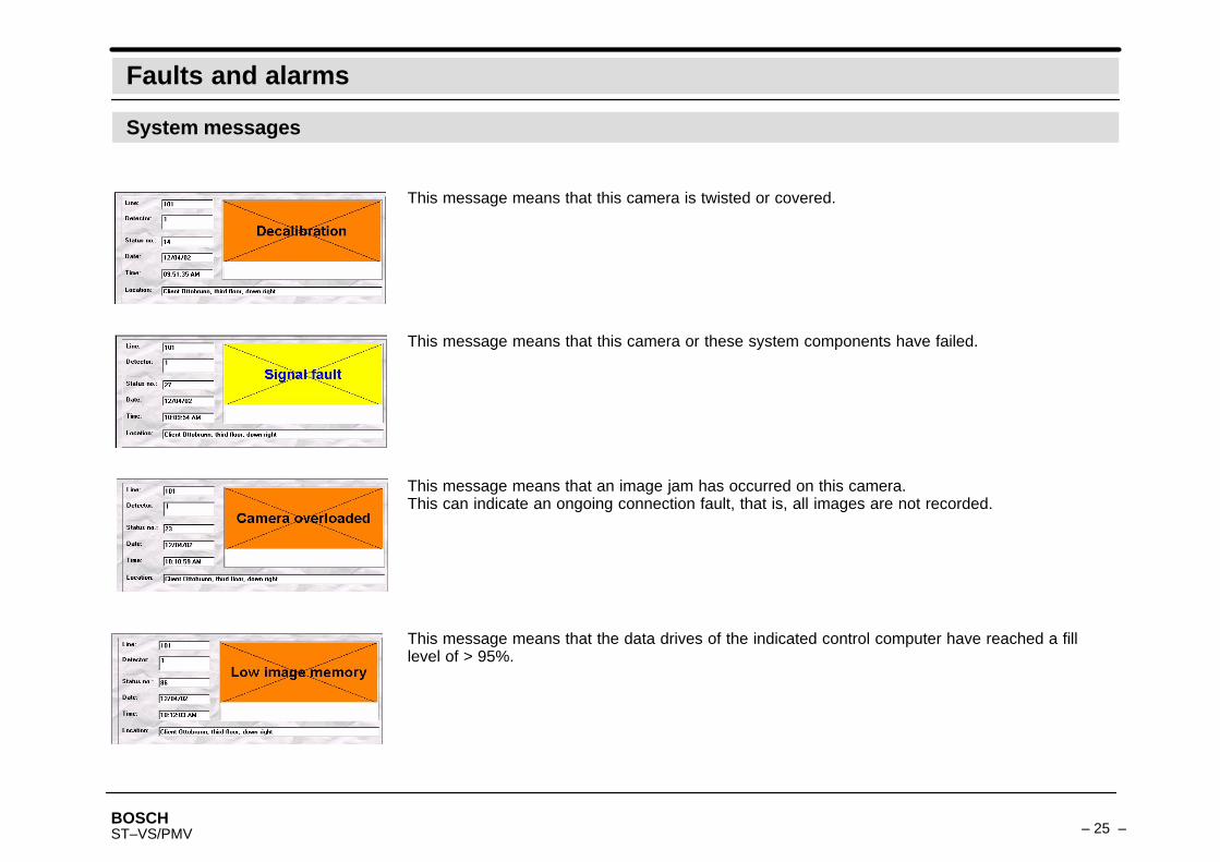
System messages
This message means that this camera is twisted or covered.
This message means that this camera or these system components have failed.
This message means that an image jam has occurred on this camera.This can indicate an ongoing connection fault, that is, all images are not recorded.
This message means that the data drives of the indicated control computer have reached a filllevel of > 95%.

BOSCH– 26 –ST–VS/PMV
Faults and alarms
System messages
For individually–selected video sensors with exterior sensors, this message appears upon thedetection of directional motion in the image. A live image and action text can be programmed(optional).
BOSCH– 27 –ST–VS/PMV
Image data backup on a medium
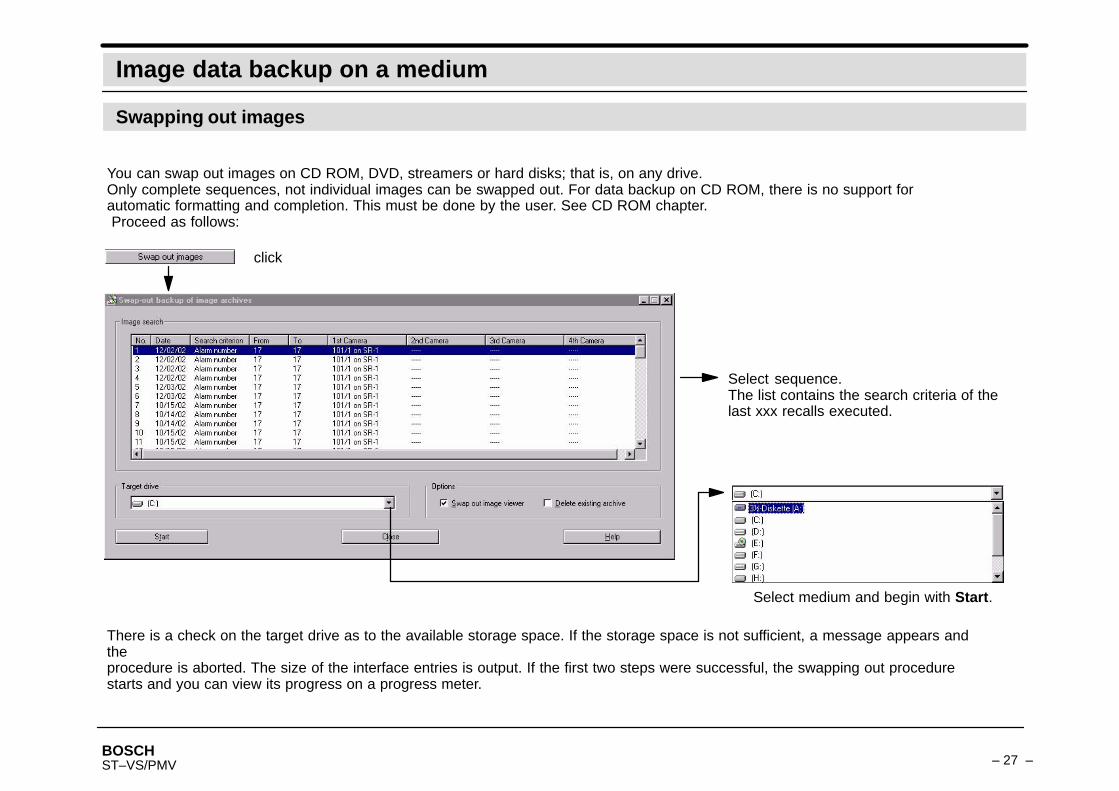
Swapping out images
You can swap out images on CD ROM, DVD, streamers or hard disks; that is, on any drive.Only complete sequences, not individual images can be swapped out. For data backup on CD ROM, there is no support forautomatic formatting and completion. This must be done by the user. See CD ROM chapter. Proceed as follows:
click
Select medium and begin with Start.
Select sequence.The list contains the search criteria of thelast xxx recalls executed.
There is a check on the target drive as to the available storage space. If the storage space is not sufficient, a message appears andtheprocedure is aborted. The size of the interface entries is output. If the first two steps were successful, the swapping out procedurestarts and you can view its progress on a progress meter.
BOSCH– 28 –ST–VS/PMV
Hard disk transport for systems with removable hard disk drives
General
Recording system
Evaluation systemShut off the evaluation system and connect the transported disks. Switch on the central connection with the “Systemstart” key and place theCD in the drive during the booting process. Only the CD entitles you to access to the external data media.Note:Please do not forget to delete the archive completely after you are finished searching on the evaluation system or central system. Onlyupon deletion of the last image is the data medium’s CD–related block cancelled. After you have finished recalling, you must format.
If a hard disk should be transported, a CD ROM with a key is created without which you cannot see the contents of thehard disk.Place a formatted CD in the CD burner.You can prepare the transport of external data media on the main menu under Administration. Click on the Prepare transport subele-ment.At the end of the fully–automatic transport preparation, this CD is ejected and the entire system with the exception of the HSR1 (maincontrol computer) that controls the shutdown and startup of the system and its external hard disk is shut off. Now shut off the externalhard drives of the HSR1 (switch at the rear of the corresponding slot). Please remove the external data media and exchange these forempty data media. Shut off the HSR1. First switch on the hard disk carrier and then the HSR1. The system will come up independently.
Note on formatting: in the chapter Appendix: CD–ROM
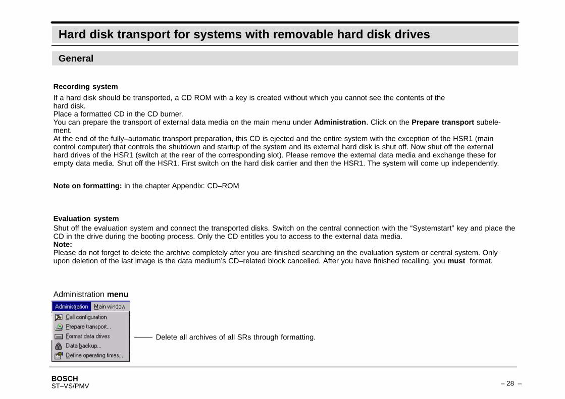
Administration menu
Delete all archives of all SRs through formatting.
BOSCH– 29 –ST–VS/PMV
Hard disk transport for systems with removable hard disk drives
Access to image data
Note:Please pay attention to the numbers of the hard disks on the front side. Insert the hard disks into their slots in ascending numerical order.Example: assigned to the SR1 1/1 to 1/X, assigned to the SR2 2/1 to 2/X, etc.To remove the data media from their brackets you must unlock the hard disk.
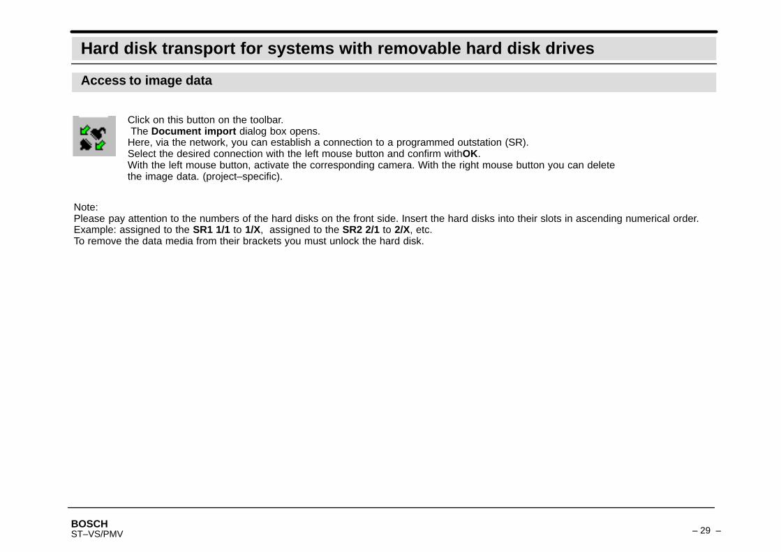
Click on this button on the toolbar. The Document import dialog box opens.Here, via the network, you can establish a connection to a programmed outstation (SR).Select the desired connection with the left mouse button and confirm withOK.With the left mouse button, activate the corresponding camera. With the right mouse button you can deletethe image data. (project–specific).

BOSCH– 30 –ST–VS/PMV
Central user workstation: access to subsystem
Change of the subsystem
If the ViStar interface is started on a central user workstation, the following dialog box appears. All configured subsystems areoffered here.
Change of the subsystem
Via this element you can select from another subsystem duringongoing operation.

BOSCH– 31 –ST–VS/PMV
Define operating times
Time programs
In the morning, the system turns itself on automatically once the system time has come. To turn it on early, press the “System start” key inthe electrical closet (optional). You then have 5 minutes’ time to create a program at the workstation that defines the current date as a holi-day and that will receive the operating times for this day from you.
Proceed as follows:
From the Administration menu, select Define operating times. The Program icons dialog box opens.
1.
BOSCH– 32 –ST–VS/PMV
Define operating times
Time programs
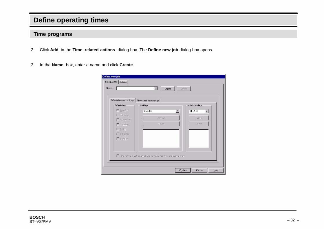
Click Add in the Time–related actions dialog box. The Define new job dialog box opens.2.
In the Name box, enter a name and click Create.3.

BOSCH– 33 –ST–VS/PMV
Define operating times
Time programs
Activate accordingly: weekdays/holidays/individual days and click Accept.4.
BOSCH– 34 –ST–VS/PMV
Define operating times
Time programs
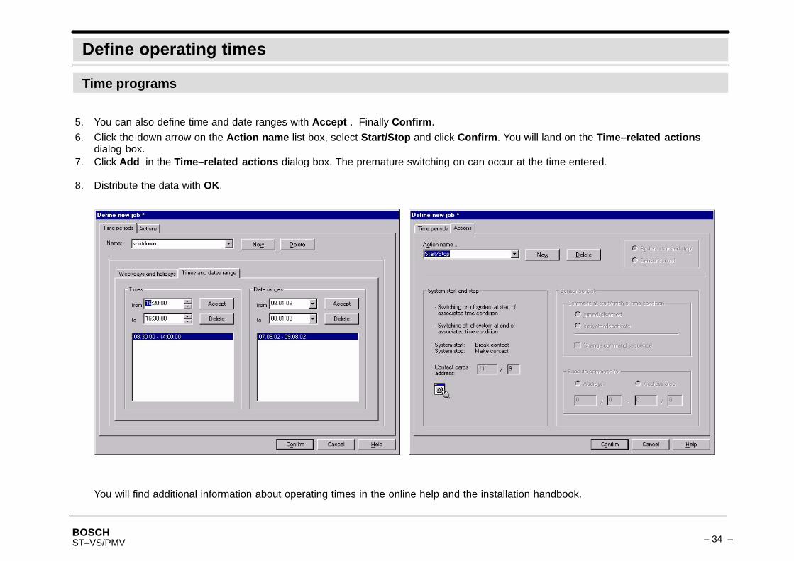
You can also define time and date ranges with Accept . Finally Confirm.5.
6. Click the down arrow on the Action name list box, select Start/Stop and click Confirm. You will land on the Time–related actionsdialog box.Click Add in the Time–related actions dialog box. The premature switching on can occur at the time entered.7.
8. Distribute the data with OK.
You will find additional information about operating times in the online help and the installation handbook.

BOSCH– 35 –ST–VS/PMV
Send e–mail and SMS to a target person
E–mail SMS
E–mail and SMS messages are sent by the ViStar system:– Automatically due to alarm or faults.– Manually from the user to the target person (technician/security guard) by clicking an action button.
The message–specific action text or camera–dependent image gives detailed information for further interventions.
BOSCH– 36 –ST–VS/PMV
Appendix: CD–ROM
All the procedures described here should be executed exclusively with single–use writeable CD ROMs. For data swapping out on CDROM, there is no support for automatic formatting and completion. This must be done by the user.
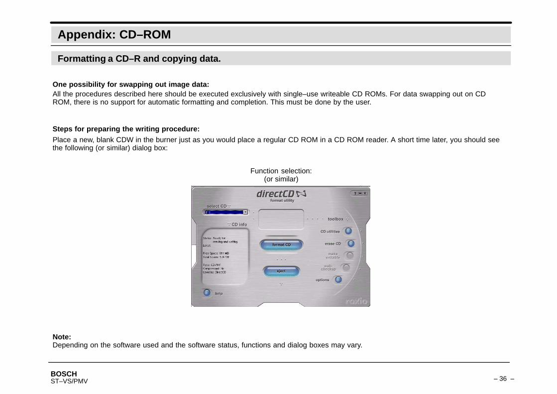
Steps for preparing the writing procedure:Place a new, blank CDW in the burner just as you would place a regular CD ROM in a CD ROM reader. A short time later, you should seethe following (or similar) dialog box:
One possibility for swapping out image data:
Function selection:(or similar)
Note:Depending on the software used and the software status, functions and dialog boxes may vary.
Formatting a CD–R and copying data.

BOSCH– 37 –ST–VS/PMV
Appendix: CD–ROM
Formatting a CD–R and copying data.
Note:the Format CD button is not available for CD–Rs that are already formatted.
To format a CD–R:– On the DirectCD window, select the desired recorder from the Select CD list.
– Click Format CD. The “Format” dialog box appears.
– Enter the name of the CD into the Identifier box.
– Click Start format. A dialog box is opened.After formatting is complete, the “CD ready” dialog box appears.
– Click ”OK”. Now you can copy files to the CD.
Before you can copy files onto a CD–R, you must format the CD–R.

BOSCH– 38 –ST–VS/PMV
Appendix: CD–ROM
Formatting a CD–R and copying data.
Copying methods:– In Explorer, you can use drag & drop to copy files to the CD recorder’s drive letter.
– From the File menu, select Save as and the recorder’s drive letter.
– In Explorer, click the right mouse button on a file and select Send to from the menu that appears.On the dialog box, select the drive letter of the CD recorder.
BOSCH– 39 –ST–VS/PMV
Notes
Sicherheitssysteme GmbH, Robert–Koch–Strasse 100,D–85521 Ottobrunn, (Postfach 1270, D–85504 Ottobrunn)Telefon (089) 6290–0, Fax (089) 6290–1020
614–4.998.142.245Edition: 1Status: May 03


