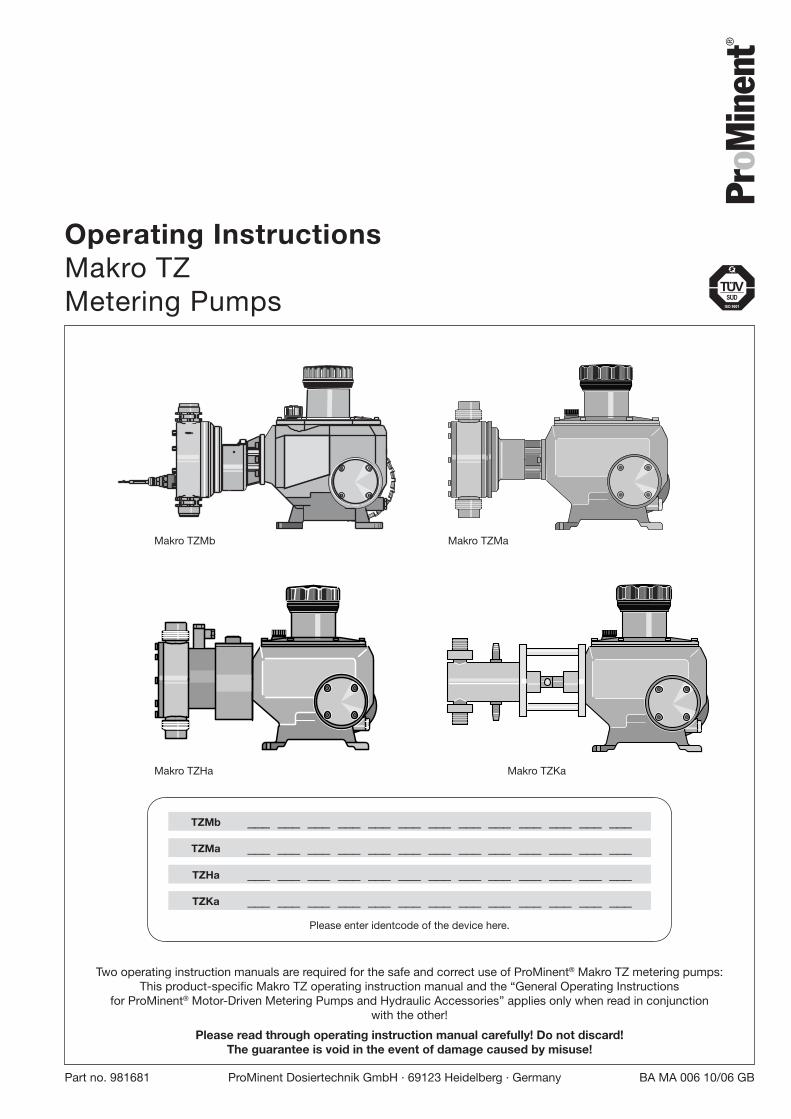
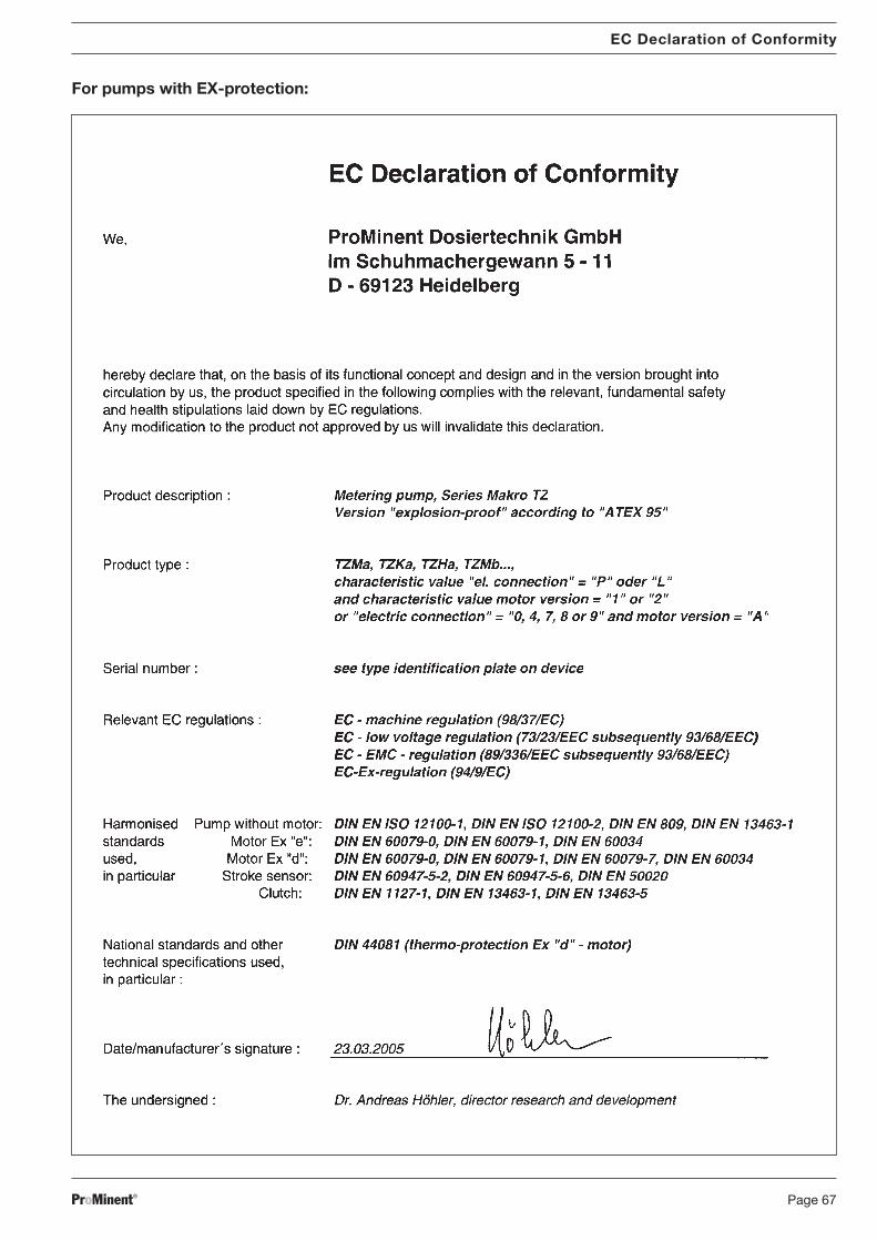
Part no. 981681 ProMinent Dosiertechnik GmbH · 69123 Heidelberg · Germany BA MA 006 10/06 GB Operating Instructions Makro TZ Metering Pumps Two operating instruction manuals are required for the safe and correct use of ProMinent ® Makro TZ metering pumps: This product-specific Makro TZ operating instruction manual and the “General Operating Instructions for ProMinent ® Motor-Driven Metering Pumps and Hydraulic Accessories” applies only when read in conjunction with the other! Please read through operating instruction manual carefully! Do not discard! The guarantee is void in the event of damage caused by misuse! Pr o Minent ® Makro TZMa Makro TZKa Makro TZHa Makro TZMb TZHa ___ ___ ___ ___ ___ ___ ___ ___ ___ ___ ___ ___ ___ TZMa ___ ___ ___ ___ ___ ___ ___ ___ ___ ___ ___ ___ ___ TZKa ___ ___ ___ ___ ___ ___ ___ ___ ___ ___ ___ ___ ___ Please enter identcode of the device here. TZMb ___ ___ ___ ___ ___ ___ ___ ___ ___ ___ ___ ___ ___
Transcript
ProMinent® Page 1Part no. 981681 ProMinent Dosiertechnik GmbH · 69123 Heidelberg · Germany BA MA 006 10/06 GB
Operating InstructionsMakro TZMetering Pumps
Two operating instruction manuals are required for the safe and correct use of ProMinent® Makro TZ metering pumps:This product-specific Makro TZ operating instruction manual and the “General Operating Instructions
for ProMinent® Motor-Driven Metering Pumps and Hydraulic Accessories” applies only when read in conjunctionwith the other!
Please read through operating instruction manual carefully! Do not discard!The guarantee is void in the event of damage caused by misuse!
13 Decommissioning and disposal ..................................... 44
14 Technical data ..................................................................... 45
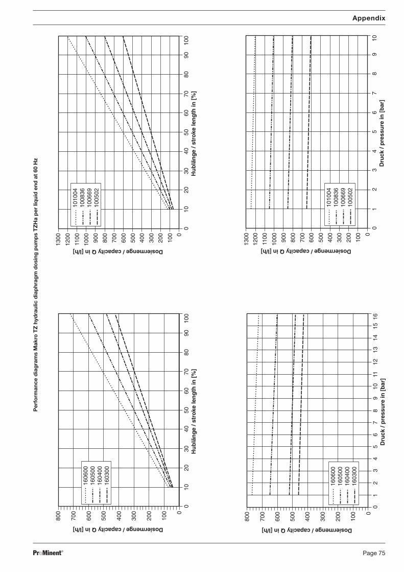
Appendix
Contents
BA_MA_TZ_006_10_06_GB.p65 05.02.2007, 13:41 Uhr3
ProMinent®Page 4
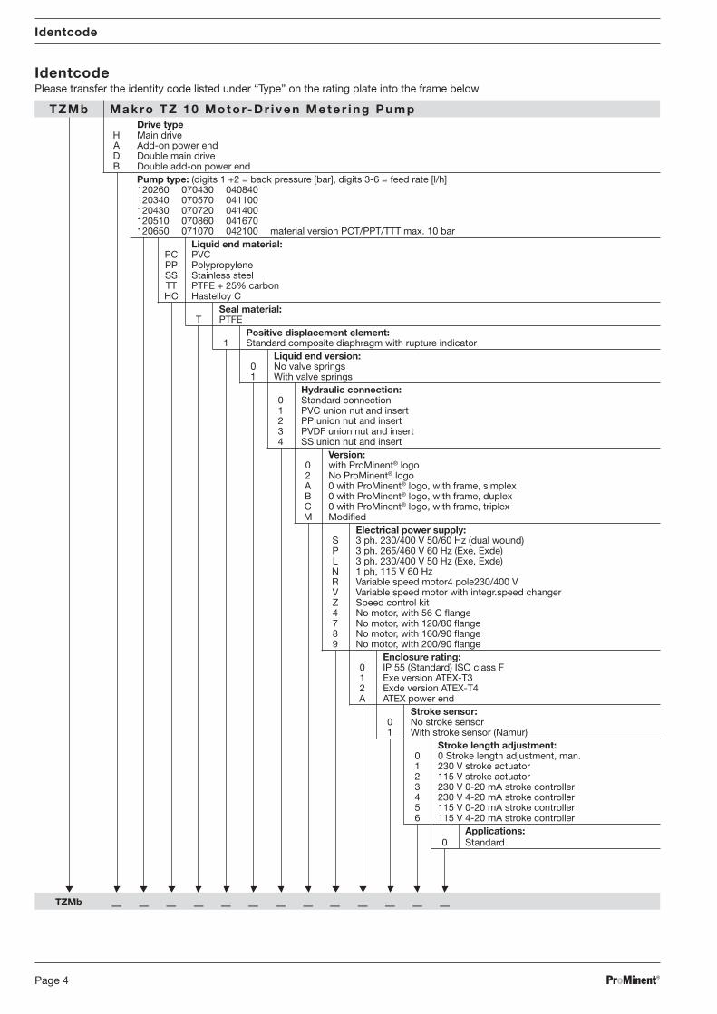
Identcode
IdentcodePlease transfer the identity code listed under “Type” on the rating plate into the frame below
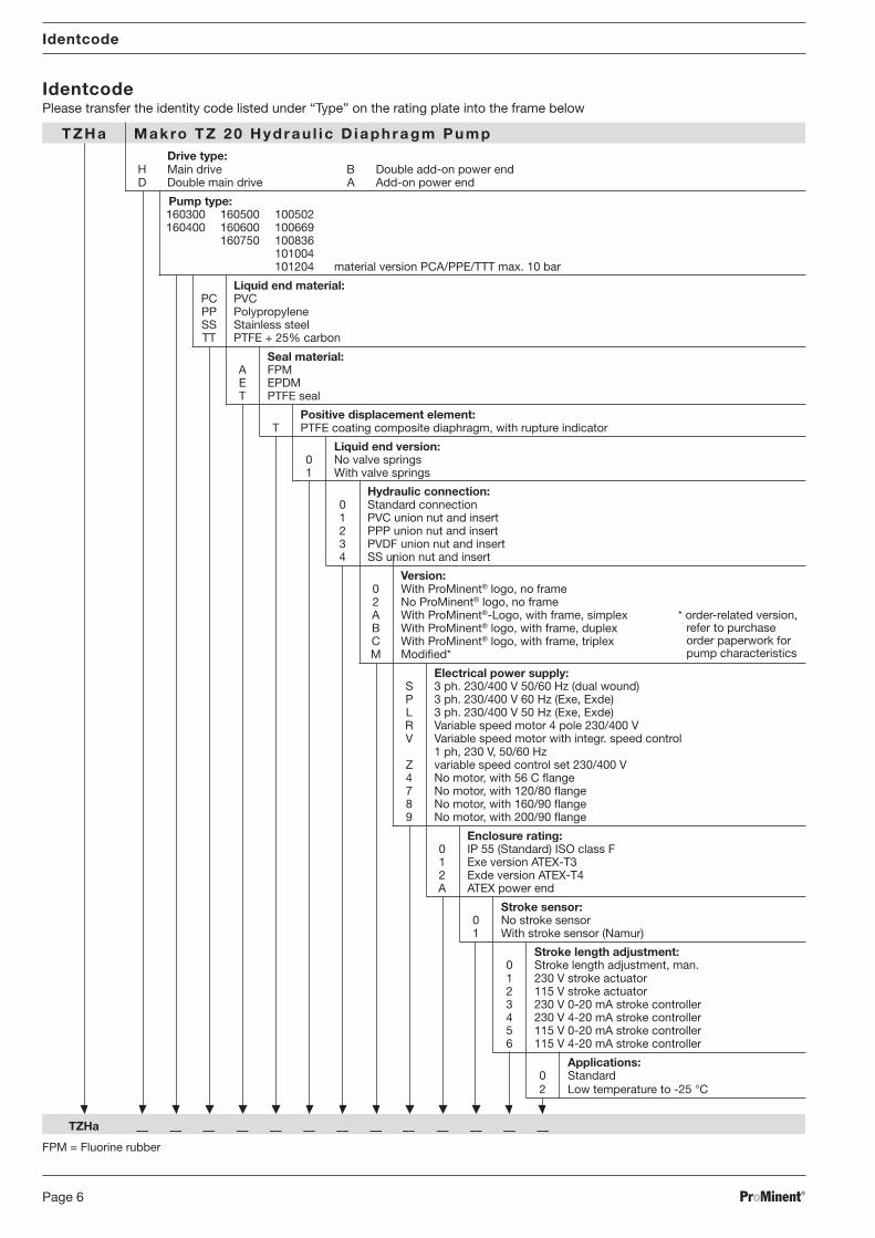
TZMb Makro TZ 10 Motor-Dr i ven Mete r ing PumpDrive type
H Main driveA Add-on power endD Double main driveB Double add-on power end
Pump type: (digits 1 +2 = back pressure [bar], digits 3-6 = feed rate [l/h]120260 070430 040840120340 070570 041100120430 070720 041400120510 070860 041670120650 071070 042100 material version PCT/PPT/TTT max. 10 bar
Liquid end material:PC PVCPP PolypropyleneSS Stainless steelTT PTFE + 25% carbonHC Hastelloy C
Seal material:T PTFE
Positive displacement element:1 Standard composite diaphragm with rupture indicator
Liquid end version:0 No valve springs1 With valve springs
Hydraulic connection:0 Standard connection1 PVC union nut and insert2 PP union nut and insert3 PVDF union nut and insert4 SS union nut and insert
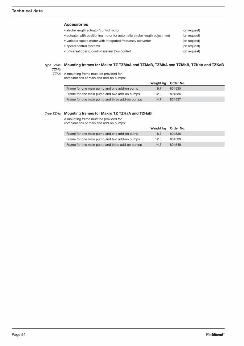
Version:0 with ProMinent® logo2 No ProMinent® logoA 0 with ProMinent® logo, with frame, simplexB 0 with ProMinent® logo, with frame, duplexC 0 with ProMinent® logo, with frame, triplexM Modified
Electrical power supply:S 3 ph. 230/400 V 50/60 Hz (dual wound)P 3 ph. 265/460 V 60 Hz (Exe, Exde)L 3 ph. 230/400 V 50 Hz (Exe, Exde)N 1 ph, 115 V 60 HzR Variable speed motor4 pole230/400 VV Variable speed motor with integr.speed changerZ Speed control kit4 No motor, with 56 C flange7 No motor, with 120/80 flange8 No motor, with 160/90 flange9 No motor, with 200/90 flange
Enclosure rating:0 IP 55 (Standard) ISO class F1 Exe version ATEX-T32 Exde version ATEX-T4A ATEX power end
Stroke sensor:0 No stroke sensor1 With stroke sensor (Namur)
Stroke length adjustment:0 0 Stroke length adjustment, man.1 230 V stroke actuator2 115 V stroke actuator3 230 V 0-20 mA stroke controller4 230 V 4-20 mA stroke controller5 115 V 0-20 mA stroke controller6 115 V 4-20 mA stroke controller
Applications:0 Standard
TZMb –– –– –– –– –– –– –– –– –– –– –– –– ––
BA_MA_TZ_006_10_06_GB.p65 05.02.2007, 13:41 Uhr4
ProMinent® Page 5
Identcode
IdentcodePlease transfer the identity code listed under “Type” on the rating plate into the frame below
* order-related version,refer to purchaseorder paperwork forpump characteristics
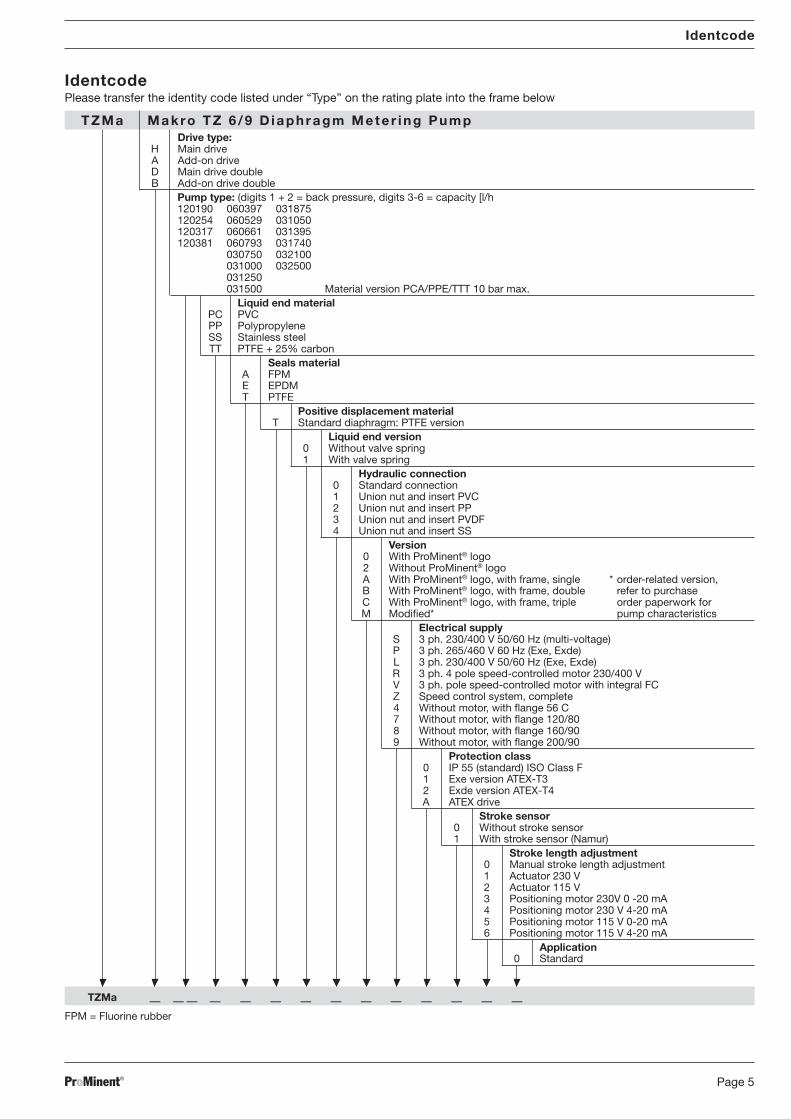
TZMa Makro TZ 6 /9 D iaphragm Mete r ing PumpDrive type:
H Main driveA Add-on driveD Main drive doubleB Add-on drive double
Positive displacement materialT Standard diaphragm: PTFE version
Liquid end version0 Without valve spring1 With valve spring
Hydraulic connection0 Standard connection1 Union nut and insert PVC2 Union nut and insert PP3 Union nut and insert PVDF4 Union nut and insert SS
Version0 With ProMinent® logo2 Without ProMinent® logoA With ProMinent® logo, with frame, singleB With ProMinent® logo, with frame, doubleC With ProMinent® logo, with frame, tripleM Modified*
Electrical supplyS 3 ph. 230/400 V 50/60 Hz (multi-voltage)P 3 ph. 265/460 V 60 Hz (Exe, Exde)L 3 ph. 230/400 V 50/60 Hz (Exe, Exde)R 3 ph. 4 pole speed-controlled motor 230/400 VV 3 ph. pole speed-controlled motor with integral FCZ Speed control system, complete4 Without motor, with flange 56 C7 Without motor, with flange 120/808 Without motor, with flange 160/909 Without motor, with flange 200/90
Protection class0 IP 55 (standard) ISO Class F1 Exe version ATEX-T32 Exde version ATEX-T4A ATEX drive
Stroke sensor0 Without stroke sensor1 With stroke sensor (Namur)
Stroke length adjustment0 Manual stroke length adjustment1 Actuator 230 V2 Actuator 115 V3 Positioning motor 230V 0 -20 mA4 Positioning motor 230 V 4-20 mA5 Positioning motor 115 V 0-20 mA6 Positioning motor 115 V 4-20 mA
Positive displacement element:T PTFE coating composite diaphragm, with rupture indicator
Liquid end version:0 No valve springs1 With valve springs
Hydraulic connection:0 Standard connection1 PVC union nut and insert2 PPP union nut and insert3 PVDF union nut and insert4 SS union nut and insert
Version:0 With ProMinent® logo, no frame2 No ProMinent® logo, no frameA With ProMinent®-Logo, with frame, simplexB With ProMinent® logo, with frame, duplexC With ProMinent® logo, with frame, triplexM Modified*
Electrical power supply:S 3 ph. 230/400 V 50/60 Hz (dual wound)P 3 ph. 230/400 V 60 Hz (Exe, Exde)L 3 ph. 230/400 V 50 Hz (Exe, Exde)R Variable speed motor 4 pole 230/400 VV Variable speed motor with integr. speed control
1 ph, 230 V, 50/60 HzZ variable speed control set 230/400 V4 No motor, with 56 C flange7 No motor, with 120/80 flange8 No motor, with 160/90 flange9 No motor, with 200/90 flange
Enclosure rating:0 IP 55 (Standard) ISO class F1 Exe version ATEX-T32 Exde version ATEX-T4A ATEX power end
Stroke sensor:0 No stroke sensor1 With stroke sensor (Namur)
Stroke length adjustment:0 Stroke length adjustment, man.1 230 V stroke actuator2 115 V stroke actuator3 230 V 0-20 mA stroke controller4 230 V 4-20 mA stroke controller5 115 V 0-20 mA stroke controller6 115 V 4-20 mA stroke controller
Applications:0 Standard2 Low temperature to -25 °C
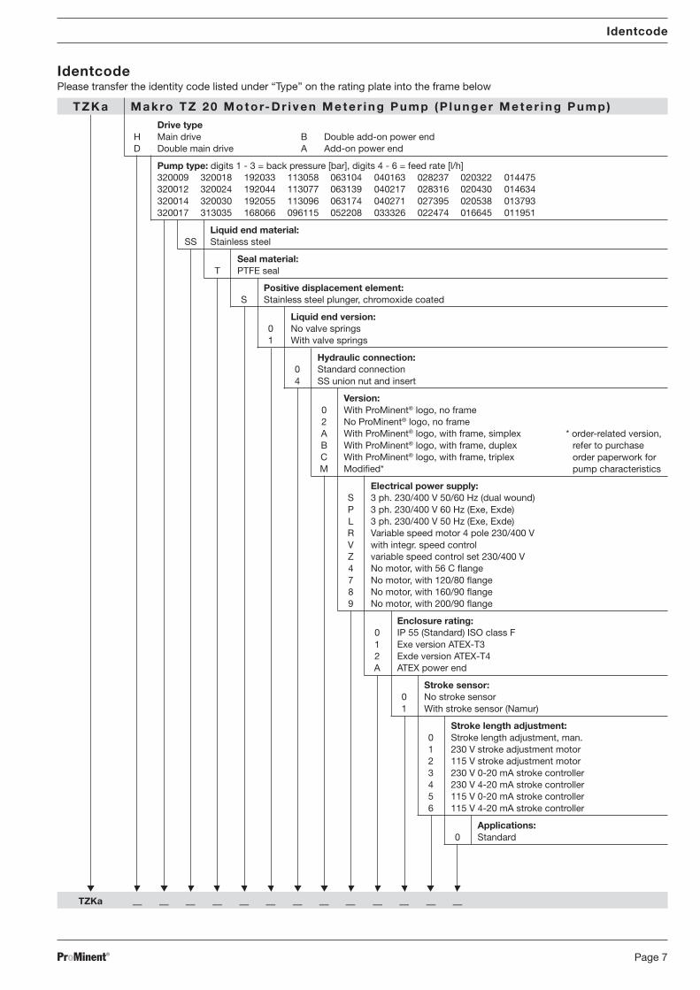
Liquid end version:0 No valve springs1 With valve springs
Hydraulic connection:0 Standard connection4 SS union nut and insert
Version:0 With ProMinent® logo, no frame2 No ProMinent® logo, no frameA With ProMinent® logo, with frame, simplexB With ProMinent® logo, with frame, duplexC With ProMinent® logo, with frame, triplexM Modified*
Electrical power supply:S 3 ph. 230/400 V 50/60 Hz (dual wound)P 3 ph. 230/400 V 60 Hz (Exe, Exde)L 3 ph. 230/400 V 50 Hz (Exe, Exde)R Variable speed motor 4 pole 230/400 VV with integr. speed controlZ variable speed control set 230/400 V4 No motor, with 56 C flange7 No motor, with 120/80 flange8 No motor, with 160/90 flange9 No motor, with 200/90 flange
Enclosure rating:0 IP 55 (Standard) ISO class F1 Exe version ATEX-T32 Exde version ATEX-T4A ATEX power end
Stroke sensor:0 No stroke sensor1 With stroke sensor (Namur)
Stroke length adjustment:0 Stroke length adjustment, man.1 230 V stroke adjustment motor2 115 V stroke adjustment motor3 230 V 0-20 mA stroke controller4 230 V 4-20 mA stroke controller5 115 V 0-20 mA stroke controller6 115 V 4-20 mA stroke controller
Applications:0 Standard
TZKa –– –– –– –– –– –– –– –– –– –– –– –– ––
BA_MA_TZ_006_10_06_GB.p65 05.02.2007, 13:41 Uhr7
ProMinent®Page 8
General user instructions
Please read through the following user instructions carefully! They will help you get the best useout of the operating instruction manual.
The following are highlighted in the text:
• Enumerated points
Instructions
Operating guidelines:
IMPORTANT
Notices are intended to make your work easier.
and safety guidelines:
WARNING
Describes a potentially dangerous situation. If not avoided, could cause fatal or serousinjury.
CAUTION
Describes a potentially dangerous situation. If not avoided, could cause slight or minorinjury or damage to property.
NOTICE
Describes a potentially damaging situation. If not avoided, could cause damage to property.
Please also note the guidelines in “General Operating Instruction Manual for ProMinent® Motor-Driven Metering Pumps and Hydraulic Accessories”!
The nameplates affixed to the title page are identical to those on the pump supplied to enable aclear allocation of the correct operating instruction manual to the pump.
Nur EX-Pumpe: Please give the order number and the serial number, which you will find on the nameplates of thepump itself, in the event of any query or spare part order. This facilitates identification of thepump.
General user instructions
BA_MA_TZ_006_10_06_GB.p65 05.02.2007, 13:41 Uhr8
ProMinent® Page 9
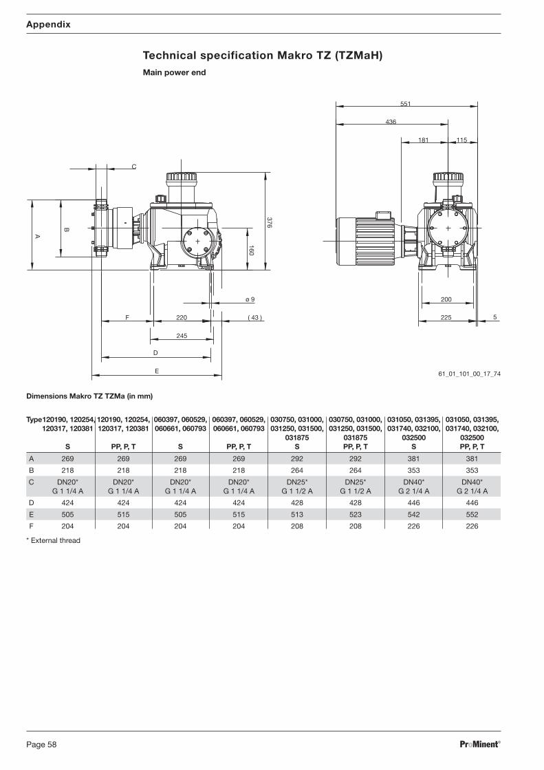
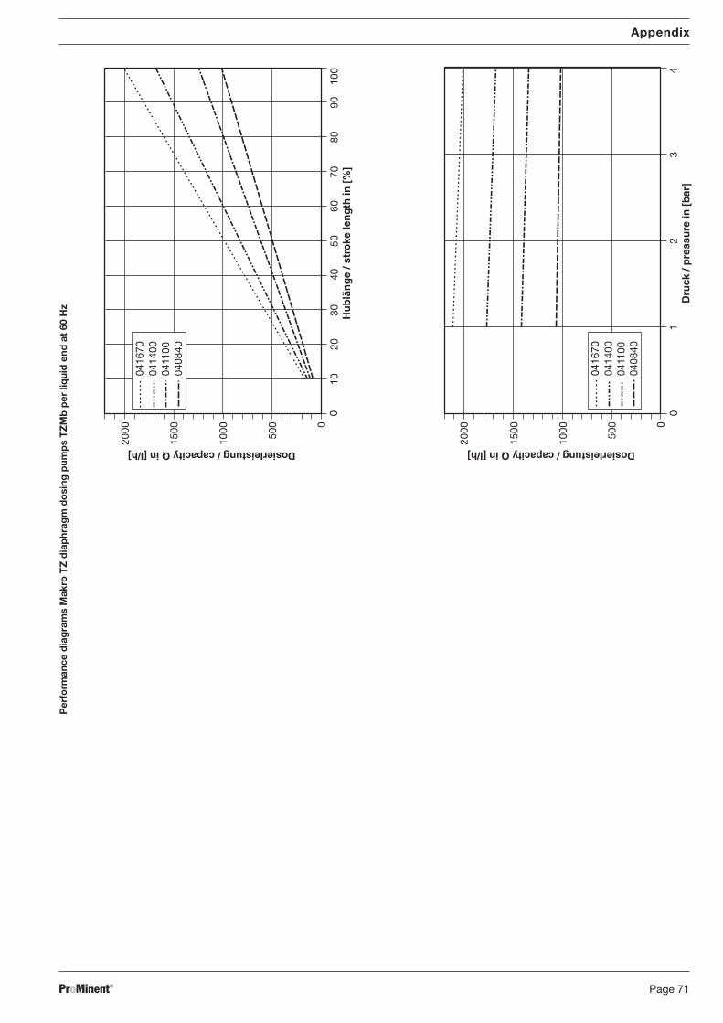
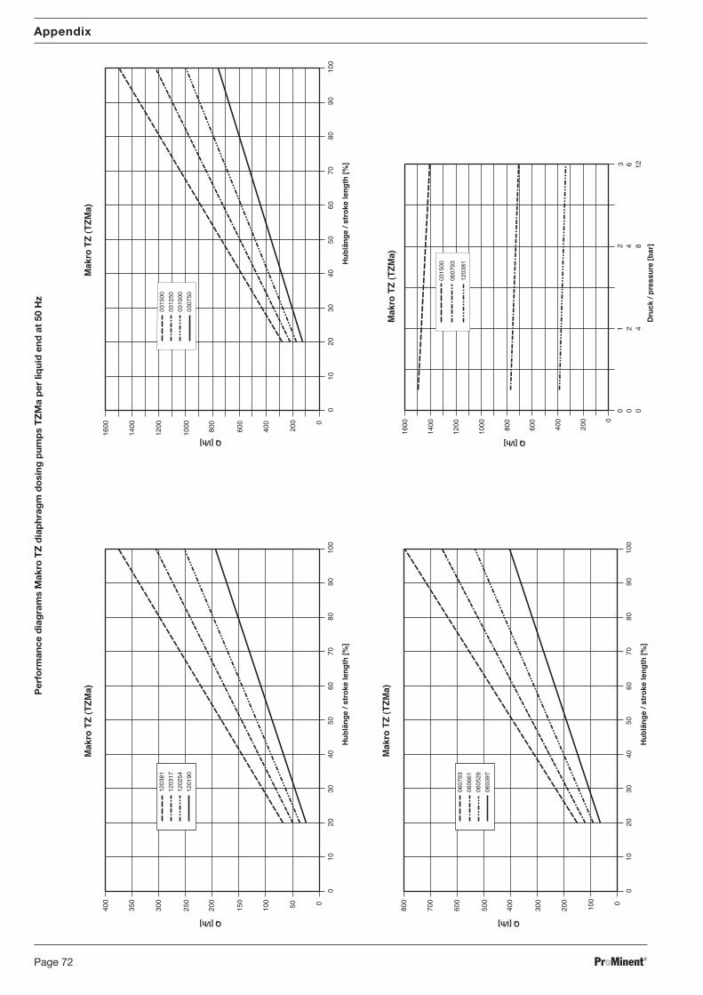
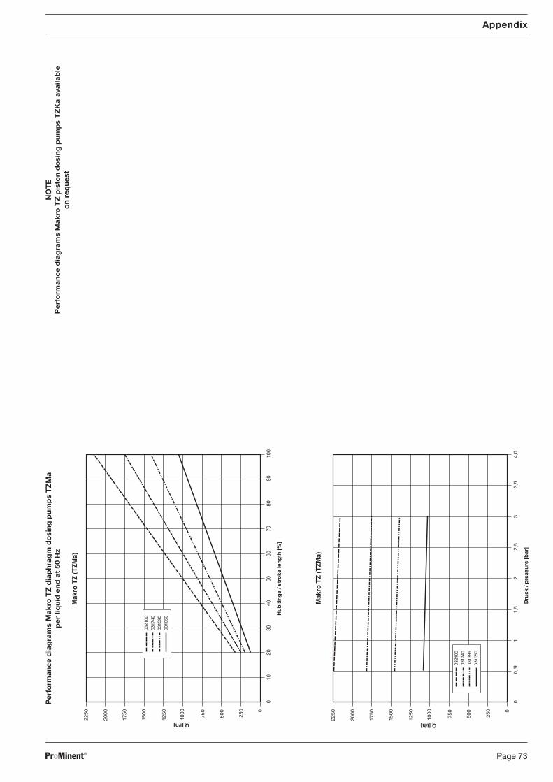
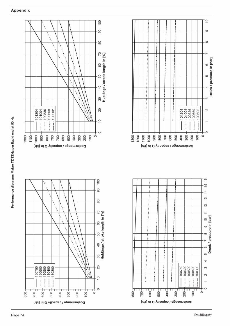
1 About this pumpProMinent® Makro TZ dosing pumps are supplied with a 1.5 kW multi-voltage three-phase motoras standard (TZMb, TZMa: 0.75 kW). The stroke length can be adjusted between 0...20 mm(TZMb: 0...10 mm, TZMa: 0...6/9 mm). The acrylic resin coated cast housing can be combinedwith up to 16 liquid ends and 5 reduction ratios. Liquid ends are available in different materialcombinations to suit the particular dosing media. The Makro TZMb is fitted with a compositediaphragm with diaphragm rupture indicator as standard. Under defined conditions and withcorrect installation, the reproducibility of the dosing with the TZKa is better than ± 0.5 % in thestroke length range from 10 %- 100 % and better than ± 1 % for the TZHa (TZMb, TZMa: ± 2 %between 30 % - 100 %).
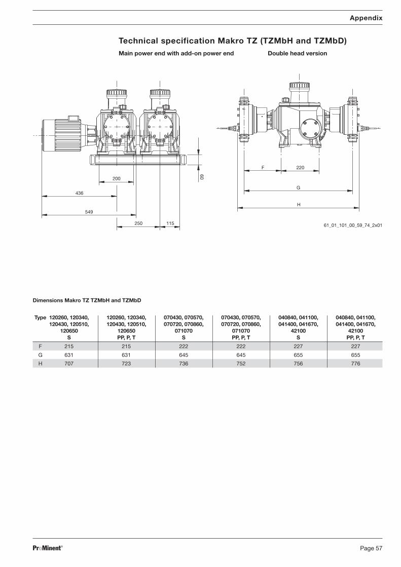
Add-on pumps The ProMinent® Makro TZ add-on metering pump can be combined with the Makro TZ mainpower end to produce a duplex/multiplex pump. A main power end can be combined with up tofour add-on power ends. One power end can be used as both a single and a double head version.
Double-head version The double head versions are fitted with a second liquid end which operates in counter cycle(Boxer principle).
2 SafetyCorrect use
of equipment Use • The pump may be used for metering liquid media only!
• The pump can be operated with the appropriate motor (TZMb, TZMa, TZHa, TZKa) and theappropriate float switch and cable on the diaphragm rupture indicator (TZHa) in areas withpotentially explosive atmospheres in Zone 1, device category II 2G of explosion group II C inaccordance with the European Directives. In this case, the pumps must have the appropriateidentifications in accordance with ATEX Directive 94/9/EC. The explosion group, category andprotection class on the identification must correspond with or be better than the givenconditions in the envisaged application.
• All other applications and modifications are prohibited!
• Pumps without the appropriate rating plate and the appropriate EC Declaration of Conformityfor areas with potentially explosive atmospheres must never be operated in areas withpotentially explosive atmospheres.
• The pumps with piston liquid ends are not suitable for metering life-threatening liquids.
• The pump is not suitable for metering gaseous media or solids.
• The pump may be used only within the stated pressure range.
• Please observe general limitations with regard to viscosity limits, chemical resistance anddensity and the stated ambient conditions.
• It is essential that you read this operating instruction manual together with the “GeneralOperating Instructions for ProMinent® Metering Pumps and Hydraulic Accessories”concerning assembly, installation and maintenance!
• The pump is to be operated by appropriately trained personnel only.
Safety instructions
WARNING
• EX pump only: Always observe the “Important supplements for dosing pumps in EXareas” section of the “General Operating Instruction for ProMinent® Motor-DrivenMetering Pumps and Hydraulic Accessories”!
• The pump starts to operate as soon as it is connected to the mains.
Ensure that hazardous media cannot leak out.
• The pump has no on/off switch.
In the event of an electrical fault, unplug the mains cable or switch off the system at theemergency off-switch.
• Unplug the cable from the mains before working on the pump!
• Always depressurise the liquid end before working on the pump!
• Before working on the pump, empty the liquid end and rinse out if it has been used withhazardous or unknown chemicals.
• Always wear suitable protective equipment when working on a liquid end which hasbeen used with hazardous or unknown chemicals.
• Pumps must be accessible at all times for operation and maintenance.Access should never be impeded or blocked.
About this pump / Safety
BA_MA_TZ_006_10_06_GB.p65 05.02.2007, 13:41 Uhr9
ProMinent®Page 10
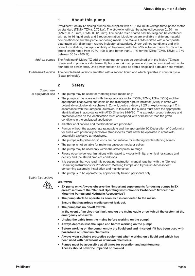
Safety
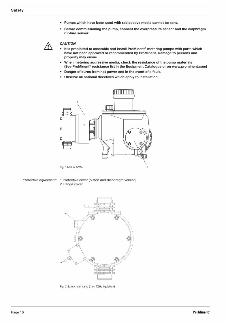
• Pumps which have been used with radioactive media cannot be sent.
• Before commissioning the pump, connect the overpressure sensor and the diaphragmrupture sensor.
CAUTION
• It is prohibited to assemble and install ProMinent® metering pumps with parts whichhave not been approved or recommended by ProMinent. Damage to persons andproperty may ensue.
• When metering aggressive media, check the resistance of the pump materials(See ProMinent® resistance list in the Equipment Catalogue or on www.prominent.com)
• Danger of burns from hot power end in the event of a fault.
• Observe all national directives which apply to installation!
Sound intensity level The sound intensity level is < 70 dB (A)at max. strokes, max stroke rate, max back pressure (water) in accordance with:DIN EN 12639 (Noise measurement, fluid pumps)
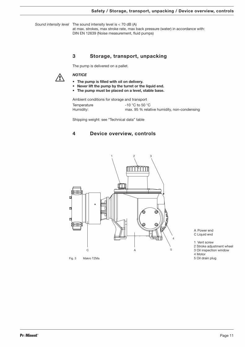
3 Storage, transport, unpacking
The pump is delivered on a pallet.
NOTICE
• The pump is filled with oil on delivery.• Never lift the pump by the turret or the liquid end.• The pump must be placed on a level, stable base.
Ambient conditions for storage and transport
Temperature -10 °C to 50 °CHumidity: max. 95 % relative humidity, non-condensing
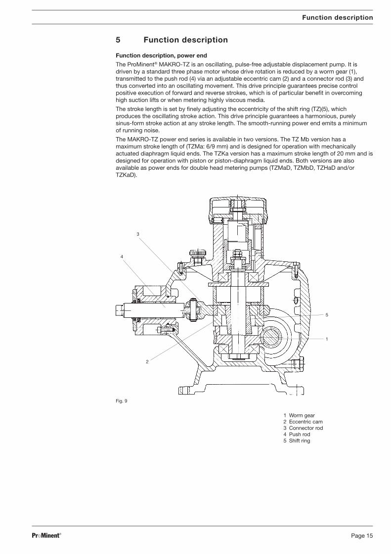
The ProMinent® MAKRO-TZ is an oscillating, pulse-free adjustable displacement pump. It isdriven by a standard three phase motor whose drive rotation is reduced by a worm gear (1),transmitted to the push rod (4) via an adjustable eccentric cam (2) and a connector rod (3) andthus converted into an oscillating movement. This drive principle guarantees precise controlpositive execution of forward and reverse strokes, which is of particular benefit in overcominghigh suction lifts or when metering highly viscous media.
The stroke length is set by finely adjusting the eccentricity of the shift ring (TZ)(5), whichproduces the oscillating stroke action. This drive principle guarantees a harmonious, purelysinus-form stroke action at any stroke length. The smooth-running power end emits a minimumof running noise.
The MAKRO-TZ power end series is available in two versions. The TZ Mb version has amaximum stroke length of (TZMa: 6/9 mm) and is designed for operation with mechanicallyactuated diaphragm liquid ends. The TZKa version has a maximum stroke length of 20 mm and isdesigned for operation with piston or piston-diaphragm liquid ends. Both versions are alsoavailable as power ends for double head metering pumps (TZMaD, TZMbD, TZHaD and/orTZKaD).
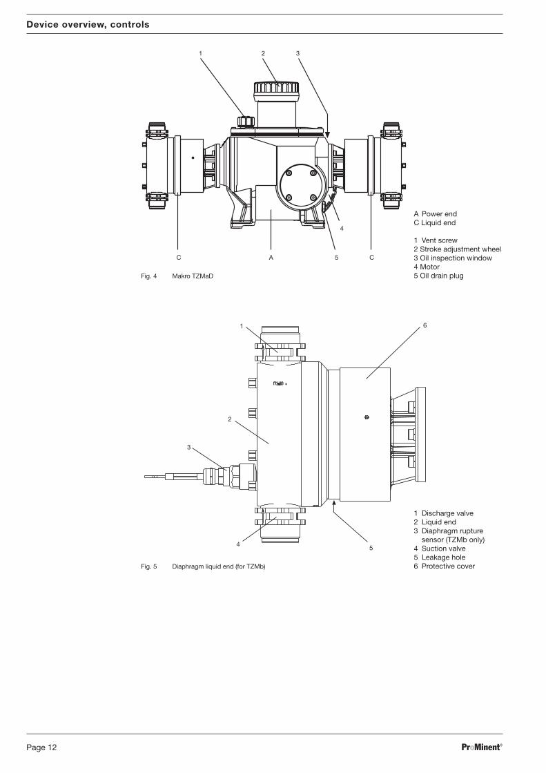
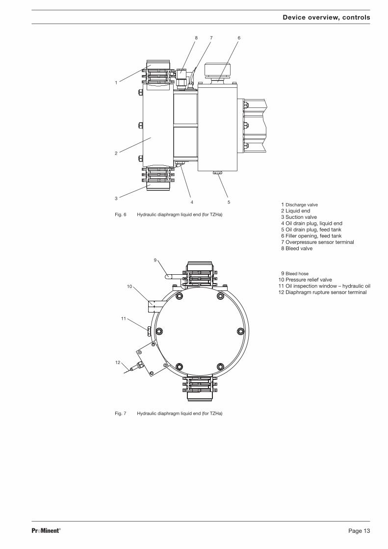
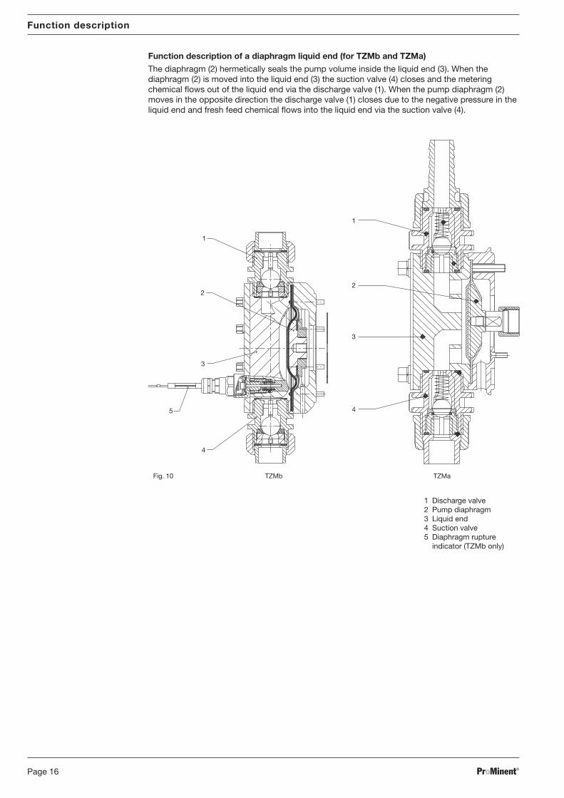
Function description of a diaphragm liquid end (for TZMb and TZMa)
The diaphragm (2) hermetically seals the pump volume inside the liquid end (3). When thediaphragm (2) is moved into the liquid end (3) the suction valve (4) closes and the meteringchemical flows out of the liquid end via the discharge valve (1). When the pump diaphragm (2)moves in the opposite direction the discharge valve (1) closes due to the negative pressure in theliquid end and fresh feed chemical flows into the liquid end via the suction valve (4).
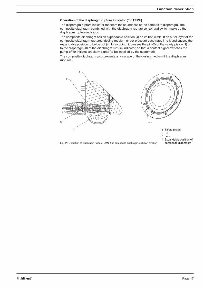
Fig. 11: Operation of diaphragm rupture TZMb (the composite diaphragm is shown smaller)
Operation of the diaphragm rupture indicator (for TZMb)
The diaphragm rupture indicator monitors the soundness of the composite diaphragm. Thecomposite diaphragm combined with the diaphragm rupture sensor and switch make up thediaphragm rupture indicator.
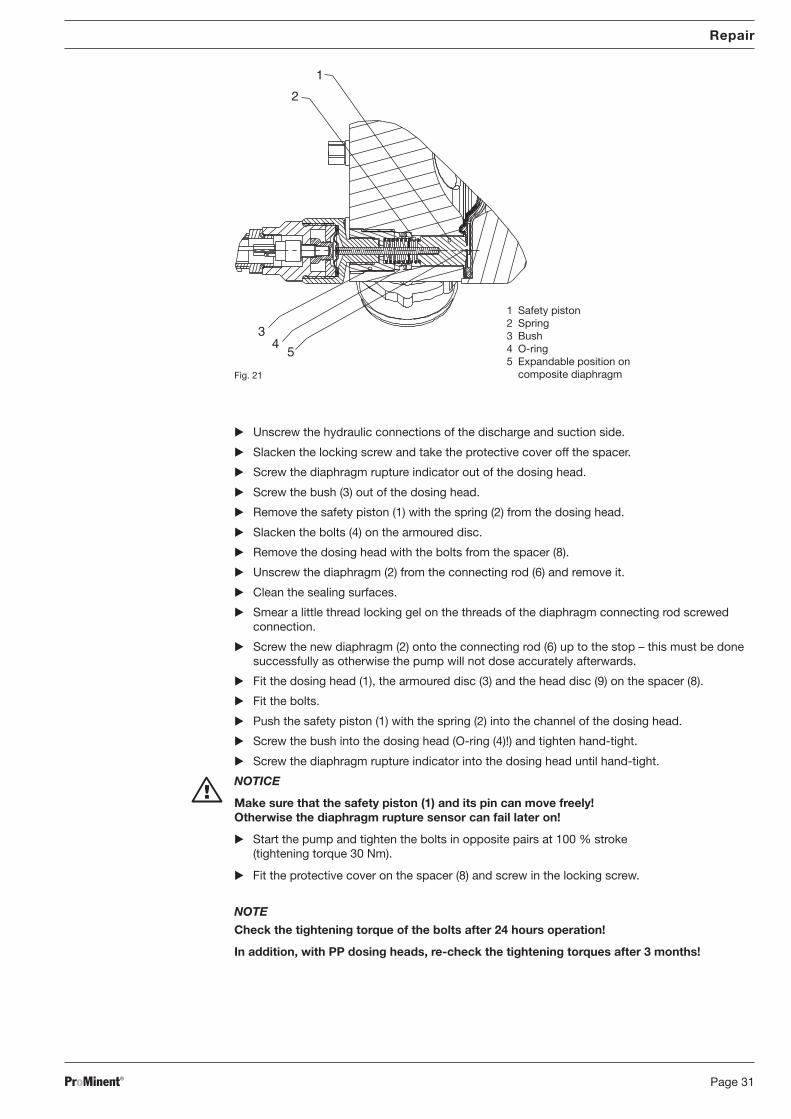
The composite diaphragm has an expandable position (4) on its bolt circle. If an outer layer of thecomposite diaphragm ruptures, dosing medium under pressure penetrates into it and causes theexpandable position to bulge out (4). In so doing, it presses the pin (2) of the safety piston (1) onto the diaphragm (3) of the diaphragm rupture indicator, so that a contact signal switches thepump off or initiates an alarm signal (to be installed by the customer!).
The composite diaphragm also prevents any escape of the dosing medium if the diaphragmruptures.
Function description
1
2
3
4
4
1 Safety piston2 Pin3 Lens4 Expandable position of
composite diaphragm
BA_MA_TZ_006_10_06_GB.p65 05.02.2007, 13:41 Uhr17
ProMinent®Page 18
Function description
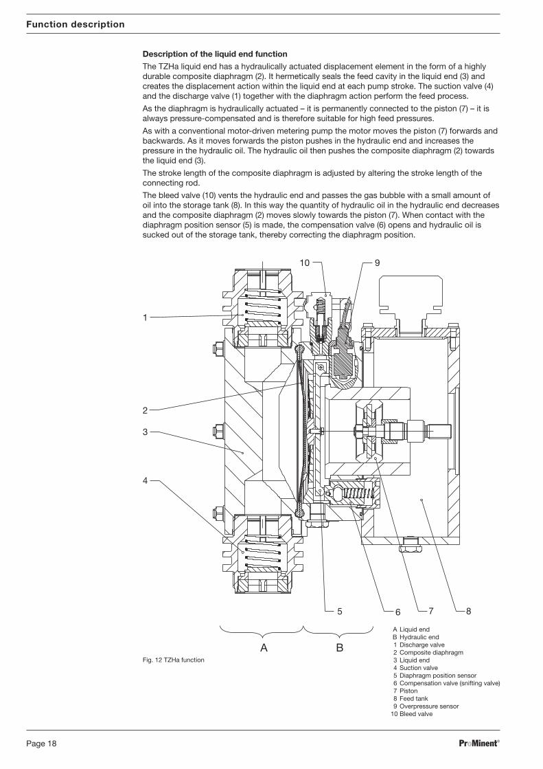
Description of the liquid end function
The TZHa liquid end has a hydraulically actuated displacement element in the form of a highlydurable composite diaphragm (2). It hermetically seals the feed cavity in the liquid end (3) andcreates the displacement action within the liquid end at each pump stroke. The suction valve (4)and the discharge valve (1) together with the diaphragm action perform the feed process.
As the diaphragm is hydraulically actuated – it is permanently connected to the piston (7) – it isalways pressure-compensated and is therefore suitable for high feed pressures.
As with a conventional motor-driven metering pump the motor moves the piston (7) forwards andbackwards. As it moves forwards the piston pushes in the hydraulic end and increases thepressure in the hydraulic oil. The hydraulic oil then pushes the composite diaphragm (2) towardsthe liquid end (3).
The stroke length of the composite diaphragm is adjusted by altering the stroke length of theconnecting rod.
The bleed valve (10) vents the hydraulic end and passes the gas bubble with a small amount ofoil into the storage tank (8). In this way the quantity of hydraulic oil in the hydraulic end decreasesand the composite diaphragm (2) moves slowly towards the piston (7). When contact with thediaphragm position sensor (5) is made, the compensation valve (6) opens and hydraulic oil issucked out of the storage tank, thereby correcting the diaphragm position.
The pump has a fixed setting pressure control valve (see Fig. 12) in the hydraulic end. Thepressure control valve protects the pump (not the system! ) together with the overpressure sensor(9) and switches off the pump when the feed pressure is too high (=overpressure fuse). If thedischarge side of the liquid end is blocked, the pressure control valve opens at the preset pressureand allows the hydraulic oil to flow back into the storage tank (8). The overpressure sensor (9)behind the pressure regulating valve then opens and its contact signal switches off the pumpimmediately (to be carried out by the customer! ). Once the system is running within the correctpressure range the hydraulic end is refilled after a few strokes via the compensation valve (6).
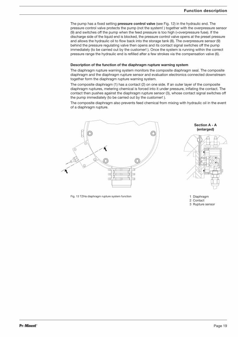
Description of the function of the diaphragm rupture warning system
The diaphragm rupture warning system monitors the composite diaphragm seal. The compositediaphragm and the diaphragm rupture sensor and evaluation electronics connected downstreamtogether form the diaphragm rupture warning system.
The composite diaphragm (1) has a contact (2) on one side. If an outer layer of the compositediaphragm ruptures, metering chemical is forced into it under pressure, inflating the contact. Thecontact then pushes against the diaphragm rupture sensor (3), whose contact signal switches offthe pump immediately (to be carried out by the customer! ).
The composite diaphragm also prevents feed chemical from mixing with hydraulic oil in the eventof a diaphragm rupture.
Function description
Fig. 13 TZHa diaphragm rupture system function 1 Diaphragm2 Contact3 Rupture sensor
BA_MA_TZ_006_10_06_GB.p65 05.02.2007, 13:41 Uhr19
ProMinent®Page 20
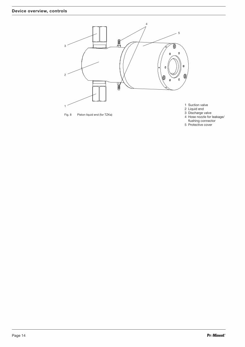
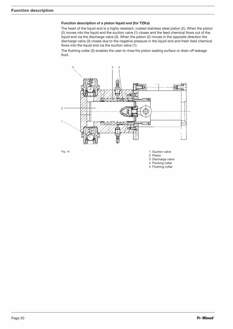
Function description of a piston liquid end (for TZKa)
The heart of the liquid end is a highly resistant, coated stainless steel piston (2). When the piston(2) moves into the liquid end the suction valve (1) closes and the feed chemical flows out of theliquid end via the discharge valve (3). When the piston (2) moves in the opposite direction thedischarge valve (3) closes due to the negative pressure in the liquid end and fresh feed chemicalflows into the liquid end via the suction valve (1).
The flushing collar (5) enables the user to rinse the piston sealing surface or drain off leakagefluid.
The pump must be bolted to an even, stable base. The base must be capable of permanentlybearing the weight of the pump. Bolt the pump with the four bolts (M8) through the four boreholes in the frame into the pump feet or base if applicable.
When fixed, the pump must not vibrate.
NOTICE
Contact ProMinent® if retrofitting an add-on pump.
7 InstallationWARNING
EX pump only: Always observe the “Important supplements for dosing pumps in EX areas”section of the “General Operating Instruction for ProMinent® Motor-Driven Metering Pumpsand Hydraulic Accessories”!
NOTICE
Also note “General Operating Instruction Manual for ProMinent® Motor-Driven Meteringpumps and Hydraulic Accessories”!
7.1 Installation, hydraulic
Liquid end
WARNING
• The liquid ends may still contain traces of water from the factory tests! If using withmedia which must not come into contact with water, ensure that the liquid ends aredried before installation. Dry with compressed air. Then rinse out by inserting a suitablerinse aid through the suction connection.
• The discharge line should be arranged to ensure that the maximum admissible pumpand system operating pressures are not exceeded during the discharge stroke.
NOTICE
• It is necessary to install a filter in the suction line for the piston liquid end if using withmedia with particle sizes greater than 0.3 mm.
• Accurate metering is possible only at a constant back pressure above 1 bar.If metering at atmospheric pressure, use a back pressure valve to generate a backpressure of approx. 1.5 bar.
Priming pressure: Maximum permissible priming pressure (suction side): 1 bar
Viscosity The liquid ends are designed for a maximum viscosity of: 200 mPa s valves without valve springs
500 mPa s valves with valve springs 1000 mPa s correspondingly designed installation
> 1000 mPa s correspondingly designed installation and after consultation with ProMinent
Leakage discharge (TZMb, TZMa and TZKa only)
Leakage fluid is drained off via the flushing collar and a hose nozzle. No other liquid end partscome into contact with the fluid.
Connect a hose to the lower hose nozzle
Feed the hose into a leakage fluid bund.
Assembly / Installation
BA_MA_TZ_006_10_06_GB.p65 05.02.2007, 13:41 Uhr21
ProMinent®Page 22
Installation
NOTICE
Ensure that dust and foreign bodies cannot penetrate through the upper hose nozzle.
The liquid end may otherwise be damaged.
Connection of flushing collar (TZKa only)
NOTICE
• The flushing medium pressure may not exceed 0.5 bar.
• The rinse aid must be suitable for the feed chemical and the liquid end materials.
• It is essential to fit a flushing assembly if using very aggressive and poisonous media,or media with low lubrication properties.
Connect the flushing assembly to the hose nozzles via two hoses.
7.2 Installation, electrical
WARNING
• EX pump only: Always observe the “Important supplements for dosing pumps inEX areas” section of the “General Operating Instruction for ProMinent® Motor-DrivenMetering Pumps and Hydraulic Accessories”!
NOTICE
• Observe the relevant directives for electrical installation.
• Observe applicable national directives.
• The device must be electrically installed by a trained and qualified person withcorresponding certification.
• Take suitable interference precautions when connecting ohmic/inductive loads.
• The motor must stop immediately if the overpressure sensor is triggered,the liquid end may otherwise be seriously damaged.
• The diaphragm rupture sensor must be connected electrically!The customer must install suitable evaluation electronics for the diaphragm rupturesignal and it must be ensured that the dosing pump is switched off after a diaphragmrupture signal!
• When the drive motor has been stopped by the diaphragm rupture sensor or theoverpressure sensor, it must not restart automatically!
• For safety reason only protective low voltages may be connected to the diaphragmrupture sensor and the overpressure sensor (SELV according to EN 60335-1).
Motor The nameplate contains important motor data.
The wiring diagram is in the terminal box.
External fan Notes on electrical connection of the motor, of the external fan in the case of variable speedmotors with external fan and the temperature monitor can be found in the “General OperatingInstruction Manual for ProMinent® Motor Driven Metering Pumps and Hydraulic Accessories”!
Stroke sensor (optional)intrinsically safe 5 -25 V DC, in accordance with Namur and/or DIN 19234 zero volts design.
Voltage rating: 8 V DC (Ri ~1 KΩ)
Power consumption:active surface uncovered >3 mAactive surface covered <1 mA
Nominal switch interval: 1.5 mm
The evaluation/power supply unit must be able to evaluate current changes in order to signal adiaphragm rupture.
BA_MA_TZ_006_10_06_GB.p65 05.02.2007, 13:41 Uhr22
ProMinent® Page 23
Installation
Cable assignment:
blue -
brown +
Diaphragm rupture sensor Standard: 30 V DC/ 1A, volt-free contact (closed in normal condition).(for TZMb) For safety reasons, the application of a separated extra-low voltage is required
(SELV in accordance with EN 60335-1).Cable assignment: any
Intrinsically safe option: observe the enclosed operating instructions of the sensor(EX pump only)!5 – 25 V DC, in accordance with Namur and DIN 19234, volt-free arrangement.
Nominal voltage: 8 V DC (Ri ~ 1 kΩ)
Current consumption:active surface clear > 3 mAactive surface covered < 1 mA
Nominal contact spacing: 1,5 mm
The evaluation / supply device must be able to evaluate the changes in current in order toindicate a diaphragm rupture.
Cable assignment:
Option
blue -
brown +
IMPORTANT
• The diaphragm rupture sensor must be connected electrically!
The customer must install suitable evaluation electronics for the diaphragm rupturesignal and it must be ensured that the dosing pump is switched off after a diaphragmrupture signal!
Diaphragm rupture sensor(for TZHa) Contact rating: 0.1 A, 250 V AC/DC
• EX pump only: Always observe the “Important supplements for dosing pumps inEX areas” section of the “General operating instructions for ProMinent dosing pumpsand hydraulic accessories”!
CAUTION
• Danger of burns from hot power end motor in the event of a fault!
NOTICE
• The pump is designed to meter liquid media within the stated capacity limits.
• Note the limitations regarding high viscosity or density of the medium.
• No life-threatening metering chemicals to be used with piston liquid end. Because oftheir manufacturing method, piston liquid ends are never hermetically sealed!
• Ensure that the liquid end materials are resistant to the feed chemical. (See ProMinent®
resistance list in the Product Catalogue or on www.prominent.com)
• The pump must be operated in accordance with the operating conditions stated in the“Technical data” section.
• It is necessary to install a filter in the suction line for the piston liquid end if using withmedia with particle sizes greater than 0.3 mm.
• Only TZHa: If no hydraulic oil flows through the hose to the bleed valve, switch off thepump immediately and contact customer service.
• Before commissioning the pump, connect the overpressure sensor and the diaphragmrupture sensor.
• The pressure control valve (TZHa) is designed to protect only the motor and the gearboxagainst inadmissible overpressure caused by the pump.
• The pressure control valve (TZHa) must not be used to bypass metering stoppages whilethe pump is running. It is a safety element.
• Do not use the pressure regulating valve (TZHa) to protect the system. It cannot protectthe system.
Setting stroke length The stroke length can be adjusted via the stroke adjustment wheel or an actuator (optional).
IMPORTANT
• It is possible to adjust the stroke length when the pump is at rest only when the liquidends have been depressurised.
• If the diaphragm rupture warning system signals a diaphragm rupture, you may continuemetering for a short period at your own risk. However, metering reproducibility isimpaired.
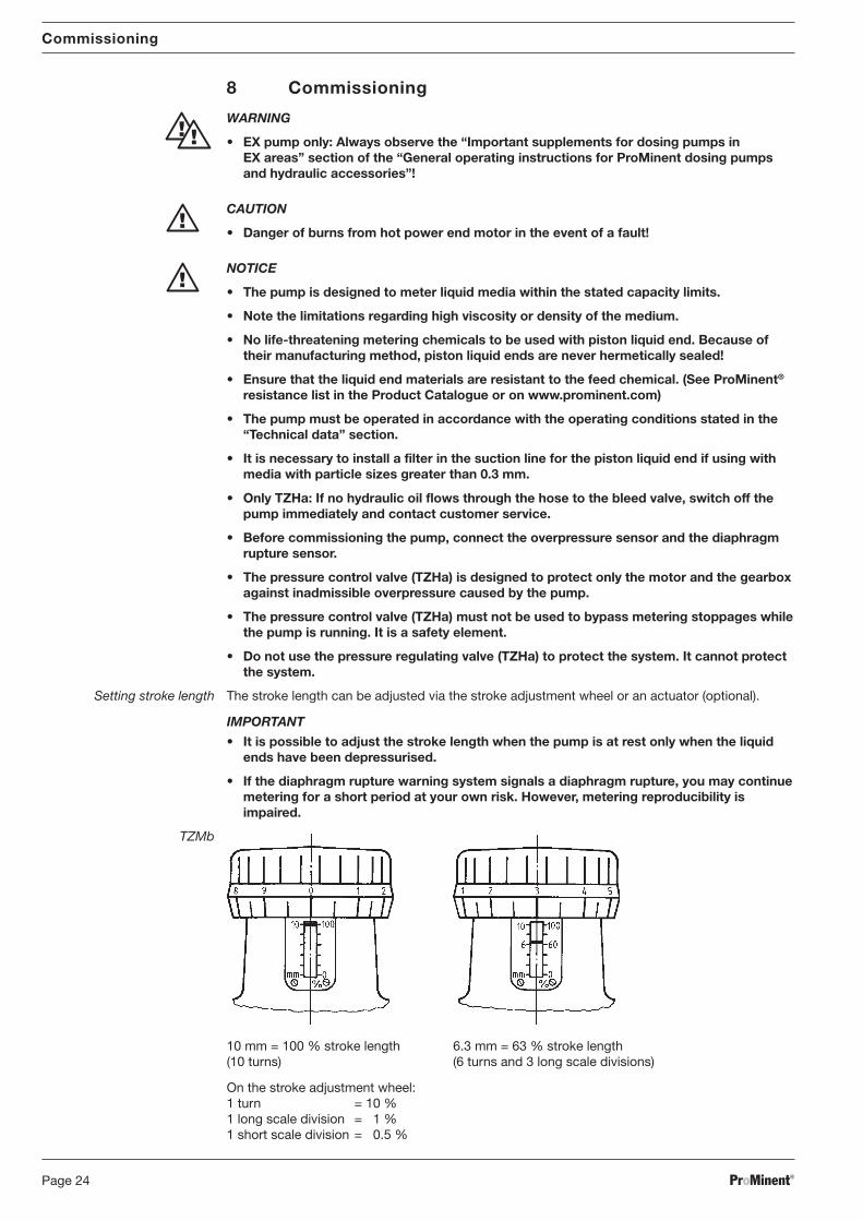
TZMb
10 mm = 100 % stroke length 6.3 mm = 63 % stroke length(10 turns) (6 turns and 3 long scale divisions)
On the stroke adjustment wheel:1 turn = 10 %1 long scale division = 1 %1 short scale division = 0.5 %
Commissioning
BA_MA_TZ_006_10_06_GB.p65 05.02.2007, 13:41 Uhr24
ProMinent® Page 25
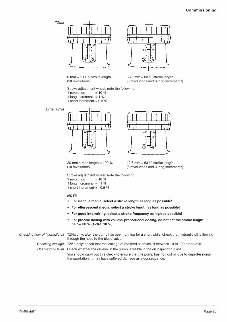
TZMa
6 mm = 100 % stroke length 3.78 mm = 63 % stroke length(10 revolutions) (6 revolutions and 3 long increments)
Stroke adjustment wheel: note the following:1 revolution = 10 %1 long increment = 1 %1 short increment = 0.5 %
TZKa, TZHa
20 mm stroke length = 100 % 12.6 mm = 63 % stroke length(10 revolutions) (6 revolutions and 3 long increments)
Stroke adjustment wheel: note the following:1 revolution = 10 %1 long increment = 1 %1 short increment = 0.5 %
NOTE
• For viscous media, select a stroke length as long as possible!
• For effervescent media, select a stroke length as long as possible!
• For good intermixing, select a stroke frequency as high as possible!
• For precise dosing with volume-proportional dosing, do not set the stroke lengthbelow 30 % (TZKa: 10 %)!
Checking flow of hydraulic oil TZHa only: after the pump has been running for a short while, check that hydraulic oil is flowingthrough the hose to the bleed valve.
Checking leakage TZKa only: check that the leakage of the feed chemical is between 10 to 120 drops/min.
Checking oil level Check whether the oil level in the pump is visible in the oil inspection glass.
You should carry out this check to ensure that the pump has not lost oil due to unprofessionaltransportation. It may have suffered damage as a consequence.
Commissioning
BA_MA_TZ_006_10_06_GB.p65 05.02.2007, 13:41 Uhr25
ProMinent®Page 26
Commissioning / Operation / Maintenance
IMPORTANT with regard to ball valve installation (single ball valve with Teflon ball seat only)
If experiencing priming problems during installation:
Ensure that there are no foreign bodies in the valve
Place valve on a stable surface
Tap the ball seat lightly with an approx. 300 g hammer and a brass rod
Allow valves to prime while wet. The pump is now ready for operation.
approx. 300 g
Brass rod
Fig. 15
The pump is now ready for operation.
9 Operation
WARNING
EX pump only: Always observe the “Important supplements for dosing pumps in EX areas”section of the “General Operating Instruction for ProMinent® Motor-Driven Metering Pumpsand Hydraulic Accessories”!
NOTICE
• Note the instructions in the “Commissioning” section and in the operating manuals forthe other machine components.
• HMH only: If hydraulic oil is not flowing through the hose to the bleed valve, stop thepump immediately and contact customer service.The liquid end may otherwise be seriously damaged.
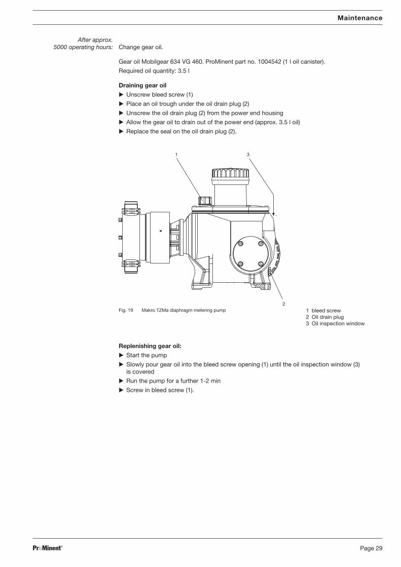
10 Maintenance
WARNING
• EX pump only: Always observe the “Important supplements for dosing pumps inEX areas” section of the “General Operating Instruction for ProMinent® Motor-DrivenMetering Pumps and Hydraulic Accessories”!
• Always depressurise the suction and discharge lines before working on the pump!
• Always empty and rinse the liquid end before maintenance or repair work if the pumphas been used with unknown or hazardous media.
BA_MA_TZ_006_10_06_GB.p65 05.02.2007, 13:41 Uhr26
ProMinent® Page 27
• Always wear suitable protective clothing to work on the liquid end when the pump hasbeen used with hazardous or unknown media.
• Metering pumps and their periphery must be maintained by qualified or authorisedpersonnel.
• Read the safety guidelines in the operating instruction manual before working on themotor.
• Always disconnect external fans, stroke positioning motor or auxiliary equipment wherepresent.
Check that the power is disconnected.
• Ensure that the pump cannot be switched on by unauthorized personnel whilemaintenance or repair work is being carried out.
IMPORTANT
Always stock spare parts kits for maintenance work.(Order numbers in “Technical data” under “Spare parts kits”! )
Services
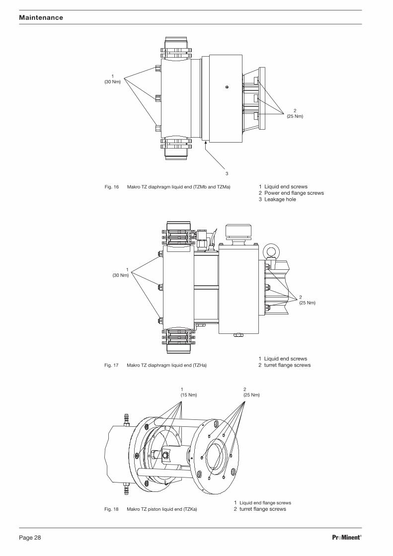
Every 3 months: • On diaphragm liquid ends (TZMb and TZMa) (see Fig. 16):check the tightening torque of the dosing head bolts (1) (30 Nm) and the drive flange bolts (2)(25 Nm)
• On hydraulic diaphragm liquid ends (TZHa) (see Fig. 17):check the tightening torque of the dosing head bolts (1) (30 Nm) and the spacer flange bolts(2) (25 Nm)
• On piston liquid ends (TZKa) (see Fig. 18):check the tightening torque of the dosing head flange bolts (1) (15 Nm) and the spacer flangebolts (2) (25 Nm)
• Check that the discharge valve and the suction valve are firmly seated
• Check that the diaphragm rupture sensor is firmly seated
• Check that the dosing lines (suction and discharge sides) are firmly seated
• Check the oil level
• Check that the pump is pumping correctly (let it run at high power for a short period but bearin mind the max. permissible operating pressure!)
• On diaphragm liquid ends (TZMb and TZMa), check whether any moisture is evident at theleakage hole (3) (if moisture is present, there is probably a diaphragm rupture).
• On piston liquid ends (TZKa), check whether the leakage rate is acceptable (10 to 12 drops/min).
• EX pump only: Always observe the “Important supplements for dosing pumps in EXareas” section of the “General Operating Instruction for ProMinent® Motor-DrivenMetering Pumps and Hydraulic Accessories”!
• Protect yourself against hazardous feed chemicals.
• Always depressurise the suction and discharge lines before working on the pump!
• Always empty the liquid end and rinse before starting maintenance and repair work ifusing dangerous or unknown media.
• Always wear suitable protective equipment to work on the liquid end when the pump hasbeen used with hazardous or unknown media.
• Isolate the supply before working on the motor and secure it against unauthorisedreconnection!
If an external fan, speed control or diaphragm rupture sensor are provided, isolate theseas well!
Check that no voltage is present!
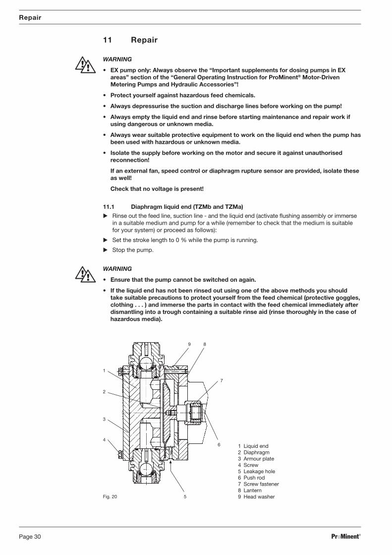
11.1 Diaphragm liquid end (TZMb and TZMa)
Rinse out the feed line, suction line - and the liquid end (activate flushing assembly or immersein a suitable medium and pump for a while (remember to check that the medium is suitablefor your system) or proceed as follows):
Set the stroke length to 0 % while the pump is running.
Stop the pump.
WARNING
• Ensure that the pump cannot be switched on again.
• If the liquid end has not been rinsed out using one of the above methods you shouldtake suitable precautions to protect yourself from the feed chemical (protective goggles,clothing . . . ) and immerse the parts in contact with the feed chemical immediately afterdismantling into a trough containing a suitable rinse aid (rinse thoroughly in the case ofhazardous media).
Unscrew the hydraulic connections of the discharge and suction side.
Slacken the locking screw and take the protective cover off the spacer.
Screw the diaphragm rupture indicator out of the dosing head.
Screw the bush (3) out of the dosing head.
Remove the safety piston (1) with the spring (2) from the dosing head.
Slacken the bolts (4) on the armoured disc.
Remove the dosing head with the bolts from the spacer (8).
Unscrew the diaphragm (2) from the connecting rod (6) and remove it.
Clean the sealing surfaces.
Smear a little thread locking gel on the threads of the diaphragm connecting rod screwedconnection.
Screw the new diaphragm (2) onto the connecting rod (6) up to the stop – this must be donesuccessfully as otherwise the pump will not dose accurately afterwards.
Fit the dosing head (1), the armoured disc (3) and the head disc (9) on the spacer (8).
Fit the bolts.
Push the safety piston (1) with the spring (2) into the channel of the dosing head.
Screw the bush into the dosing head (O-ring (4)!) and tighten hand-tight.
Screw the diaphragm rupture indicator into the dosing head until hand-tight.
NOTICE
Make sure that the safety piston (1) and its pin can move freely!Otherwise the diaphragm rupture sensor can fail later on!
Start the pump and tighten the bolts in opposite pairs at 100 % stroke(tightening torque 30 Nm).
Fit the protective cover on the spacer (8) and screw in the locking screw.
NOTE
Check the tightening torque of the bolts after 24 hours operation!
In addition, with PP dosing heads, re-check the tightening torques after 3 months!
Repair
Fig. 21
1 Safety piston2 Spring3 Bush4 O-ring5 Expandable position on
composite diaphragm
1
2
34
5
BA_MA_TZ_006_10_06_GB.p65 05.02.2007, 13:41 Uhr31
ProMinent®Page 32
Repair
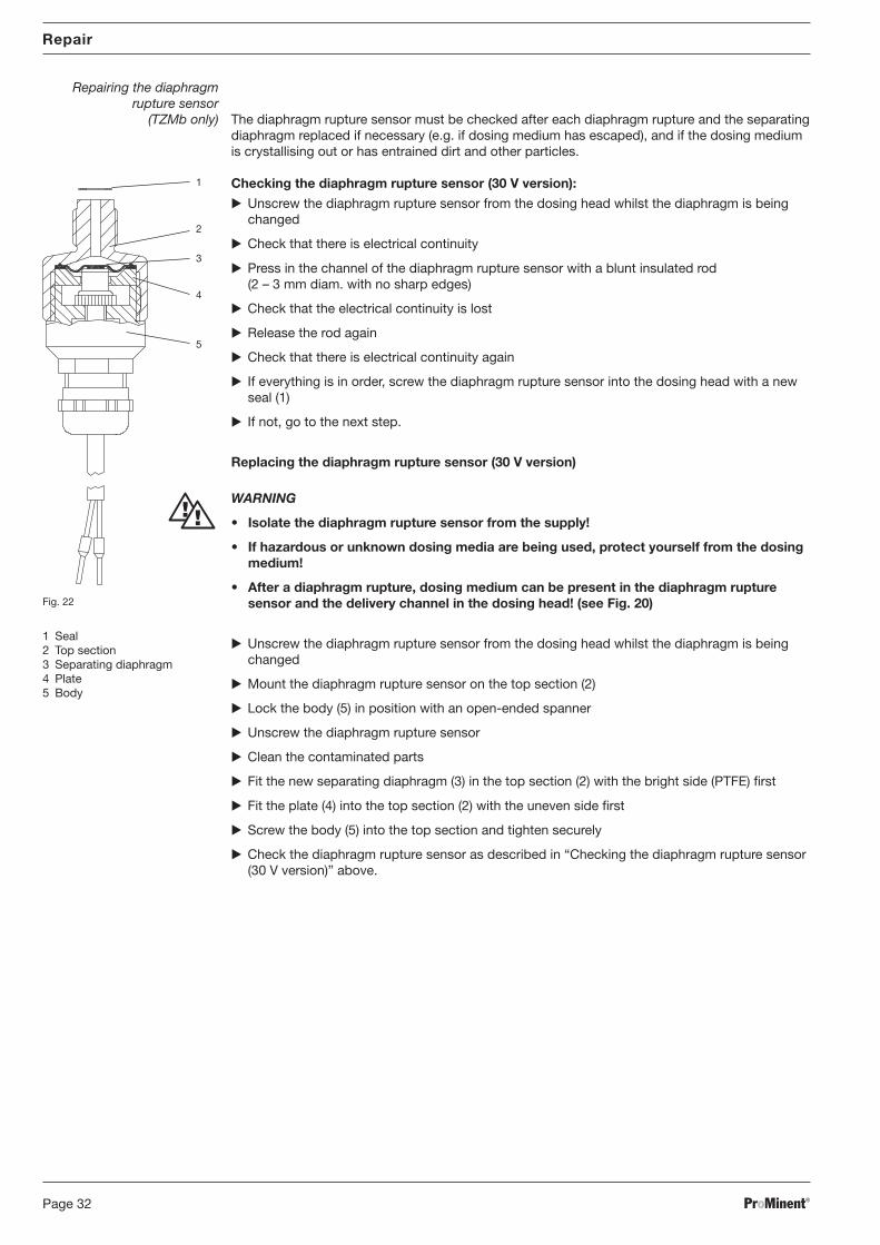
Repairing the diaphragmrupture sensor
(TZMb only) The diaphragm rupture sensor must be checked after each diaphragm rupture and the separatingdiaphragm replaced if necessary (e.g. if dosing medium has escaped), and if the dosing mediumis crystallising out or has entrained dirt and other particles.
Checking the diaphragm rupture sensor (30 V version):
Unscrew the diaphragm rupture sensor from the dosing head whilst the diaphragm is beingchanged
Check that there is electrical continuity
Press in the channel of the diaphragm rupture sensor with a blunt insulated rod(2 – 3 mm diam. with no sharp edges)
Check that the electrical continuity is lost
Release the rod again
Check that there is electrical continuity again
If everything is in order, screw the diaphragm rupture sensor into the dosing head with a newseal (1)
If not, go to the next step.
Replacing the diaphragm rupture sensor (30 V version)
WARNING
• Isolate the diaphragm rupture sensor from the supply!
• If hazardous or unknown dosing media are being used, protect yourself from the dosingmedium!
• After a diaphragm rupture, dosing medium can be present in the diaphragm rupturesensor and the delivery channel in the dosing head! (see Fig. 20)
Unscrew the diaphragm rupture sensor from the dosing head whilst the diaphragm is beingchanged
Mount the diaphragm rupture sensor on the top section (2)
Lock the body (5) in position with an open-ended spanner
Unscrew the diaphragm rupture sensor
Clean the contaminated parts
Fit the new separating diaphragm (3) in the top section (2) with the bright side (PTFE) first
Fit the plate (4) into the top section (2) with the uneven side first
Screw the body (5) into the top section and tighten securely
Check the diaphragm rupture sensor as described in “Checking the diaphragm rupture sensor(30 V version)” above.
1 Seal2 Top section3 Separating diaphragm4 Plate5 Body
Fig. 22
2
4
3
1
5
BA_MA_TZ_006_10_06_GB.p65 05.02.2007, 13:41 Uhr32
ProMinent® Page 33
Repair
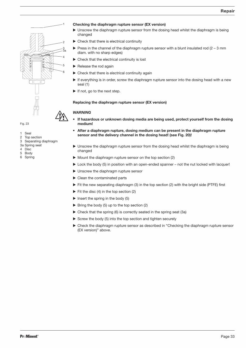
Checking the diaphragm rupture sensor (EX version)
Unscrew the diaphragm rupture sensor from the dosing head whilst the diaphragm is beingchanged
Check that there is electrical continuity
Press in the channel of the diaphragm rupture sensor with a blunt insulated rod (2 – 3 mmdiam. with no sharp edges)
Check that the electrical continuity is lost
Release the rod again
Check that there is electrical continuity again
If everything is in order, screw the diaphragm rupture sensor into the dosing head with a newseal (1)
If not, go to the next step.
Replacing the diaphragm rupture sensor (EX version)
WARNING
• If hazardous or unknown dosing media are being used, protect yourself from the dosingmedium!
• After a diaphragm rupture, dosing medium can be present in the diaphragm rupturesensor and the delivery channel in the dosing head! (see Fig. 20)!
Unscrew the diaphragm rupture sensor from the dosing head whilst the diaphragm is beingchanged
Mount the diaphragm rupture sensor on the top section (2)
Lock the body (5) in position with an open-ended spanner – not the nut locked with lacquer!
Unscrew the diaphragm rupture sensor
Clean the contaminated parts
Fit the new separating diaphragm (3) in the top section (2) with the bright side (PTFE) first
Fit the disc (4) in the top section (2)
Insert the spring in the body (5)
Bring the body (5) up to the top section (2)
Check that the spring (6) is correctly seated in the spring seat (3a)
Screw the body (5) into the top section and tighten securely
Check the diaphragm rupture sensor as described in “Checking the diaphragm rupture sensor(EX version)” above.
1
2
3a
6
3
5
4
1 Seal2 Top section3 Separating diaphragm3a Spring seat4 Disc5 Body6 Spring
Fig. 23
BA_MA_TZ_006_10_06_GB.p65 05.02.2007, 13:41 Uhr33
ProMinent®Page 34
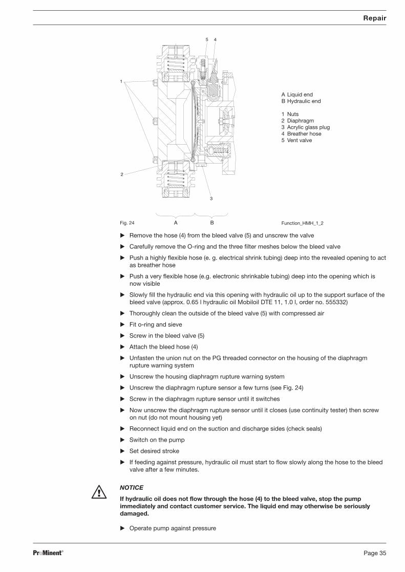
11.2 Hydraulic diaphragm liquid end (TZHa)
Set stroke adjustment knob to 0 %
Unfasten union nuts and/or flange on valves and detach lines
Empty liquid end and rinse is necessary
Place an oil trough underneath the liquid end and hydraulic end
Drain out the hydraulic oil from the hydraulic end via the acrylic glass stopper (3) (see Fig.)
Lightly screw in the acrylic glass stopper (3)
Unscrew the orange cover from the diaphragm rupture warning system (see Fig.)
Untighten the 6 nuts (1) on the liquid end (oil trough?)
Carefully remove the liquid end from the stud bolts
NOTICE
Contaminants must never be allowed to enter the hydraulic end.
Remove the diaphragm (3) (oil trough?)
Clean the sealing surfaces on the liquid end and the hydraulic end (using a suitable cleaningagent if necessary)
Place the new diaphragm (3) with the light grey coating facing outwards onto the hydraulicend
Tighten the orange cover for the diaphragm rupture warning system until the diaphragm isloosely held in position
push the liquid end over the stud bolts onto the hydraulic end (is the cut-out on the side ofthe liquid end located on the side of the diaphragm rupture warning system?)
Check that the diaphragm contact is resting easily in the diaphragm rupture warning systemhousing
Tighten the 6 nuts (1) on the liquid end to 30 Nm (torque wrench! )
Screw the orange cover onto the diaphragm rupture warning system
Repair
BA_MA_TZ_006_10_06_GB.p65 05.02.2007, 13:41 Uhr34
ProMinent® Page 35
Remove the hose (4) from the bleed valve (5) and unscrew the valve
Carefully remove the O-ring and the three filter meshes below the bleed valve
Push a highly flexible hose (e. g. electrical shrink tubing) deep into the revealed opening to actas breather hose
Push a very flexible hose (e.g. electronic shrinkable tubing) deep into the opening which isnow visible
Slowly fill the hydraulic end via this opening with hydraulic oil up to the support surface of thebleed valve (approx. 0.65 l hydraulic oil Mobiloil DTE 11, 1.0 l, order no. 555332)
Thoroughly clean the outside of the bleed valve (5) with compressed air
Fit o-ring and sieve
Screw in the bleed valve (5)
Attach the bleed hose (4)
Unfasten the union nut on the PG threaded connector on the housing of the diaphragmrupture warning system
Unscrew the housing diaphragm rupture warning system
Unscrew the diaphragm rupture sensor a few turns (see Fig. 24)
Screw in the diaphragm rupture sensor until it switches
Now unscrew the diaphragm rupture sensor until it closes (use continuity tester) then screwon nut (do not mount housing yet)
Reconnect liquid end on the suction and discharge sides (check seals)
Switch on the pump
Set desired stroke
If feeding against pressure, hydraulic oil must start to flow slowly along the hose to the bleedvalve after a few minutes.
NOTICE
If hydraulic oil does not flow through the hose (4) to the bleed valve, stop the pumpimmediately and contact customer service. The liquid end may otherwise be seriouslydamaged.
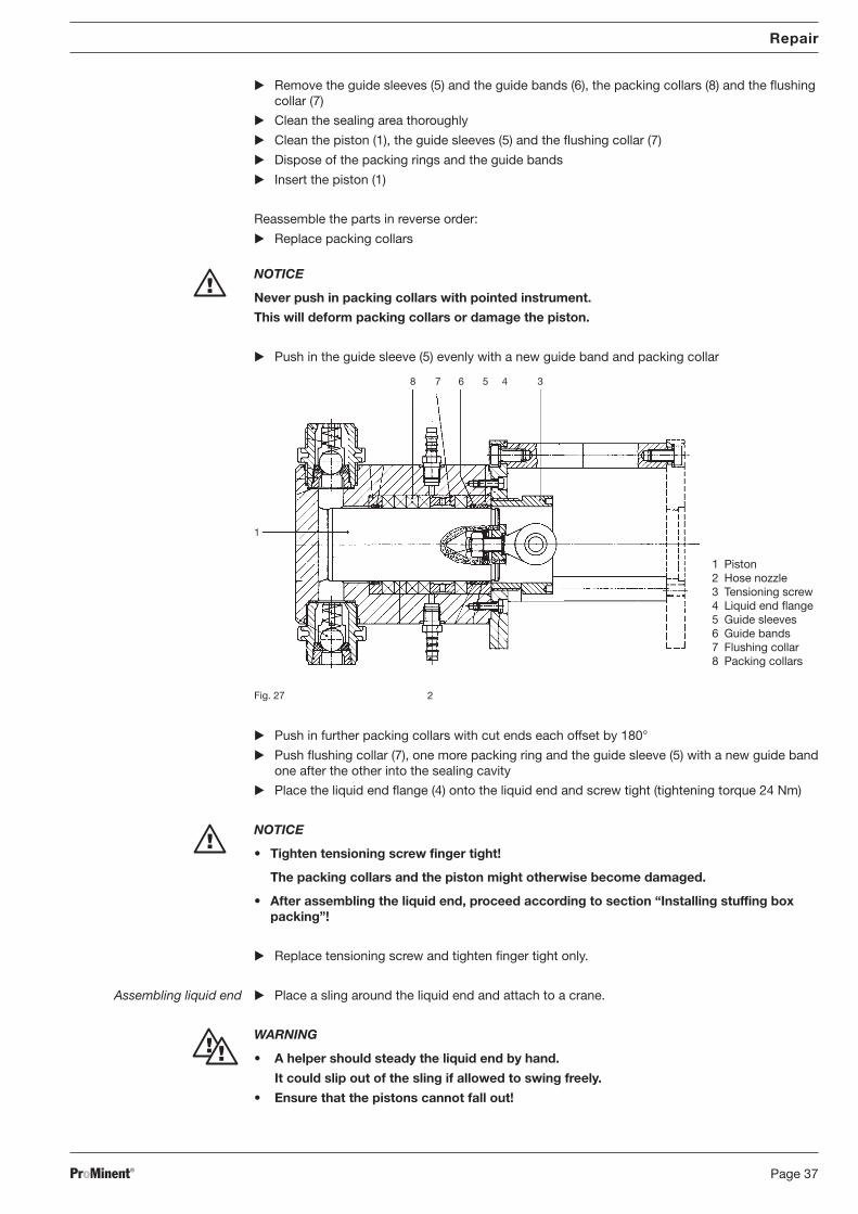
Allow pump to run for the first 10–15 min with a leakage of 50–200 drops/min.Then:1. Stop the pump2. Remove protective cover3. Carefully tighten tensioning screw4. Clamp the protective cover over the turret bolt5. Start the pump6. Check the leakageRepeat steps 1-6 until the minimum leakage is achieved (10 and 120 drops/min.).(Depends on the feed chemical, the pressure of the chemical, the temperature and the pistonspeed.)
NOTICE
Do not over-tighten the tensioning screw.If it is too tight, the system might run dry which would cause damage to the piston and thepacking collars.
Result of over-tightened tensioning screw:
The feed chemical can no longer penetrate through the packing collars – the liquid lubrication issuppressed. The piston is not lubricated. The packing collars will burn and the piston will bedamaged. Leakage will increase sharply.
Repair
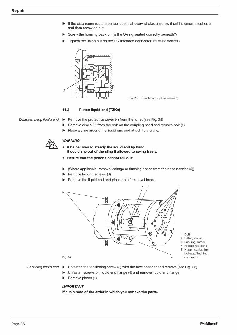
Positioning liquid end Place the liquid end onto the power end flange and screw in place (tightening torque 25 Nm) Grease the front end surfaces of the jointed head and the fork head
Line up the holes of the coupling head and the fork head (see Fig. 22)
Push bolt through the holes and insert safety collar into the bolt
Clamp the protective cover above the turret bolt
(Where applicable: attach leakage or flushing hoses to the hose nozzles)
Commissioning packingcollars Packing collars should not prevent feed chemical from leaking. Leakage is necessary to reduce
friction and to draw off the heat produced by friction.
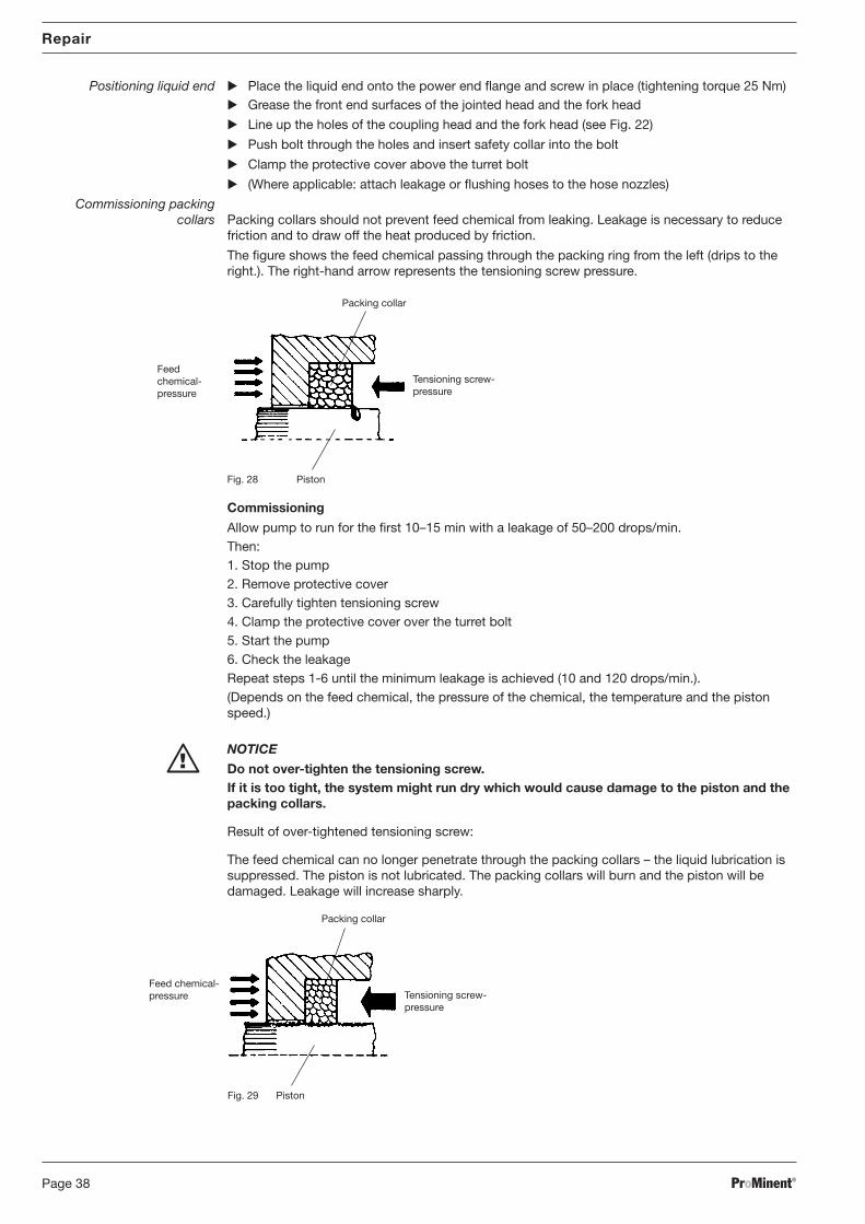
The figure shows the feed chemical passing through the packing ring from the left (drips to theright.). The right-hand arrow represents the tensioning screw pressure.
Packing collar
Tensioning screw-pressure
Piston
Feedchemical-pressure
Fig. 28
Packing collar
PistonFig. 29
Tensioning screw-pressure
Feed chemical-pressure
BA_MA_TZ_006_10_06_GB.p65 05.02.2007, 13:41 Uhr38
ProMinent® Page 39
Repair
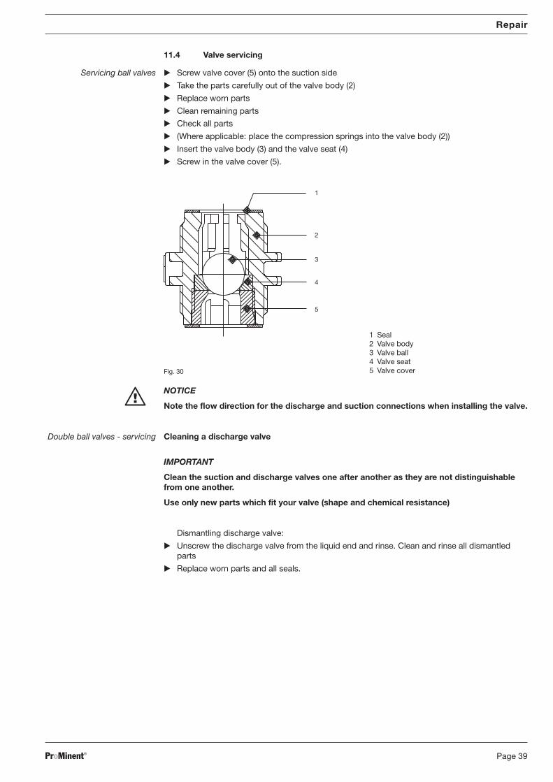
11.4 Valve servicing
Servicing ball valves Screw valve cover (5) onto the suction side
Take the parts carefully out of the valve body (2)
Replace worn parts
Clean remaining parts
Check all parts
(Where applicable: place the compression springs into the valve body (2))
Note the flow direction for the discharge and suction connections when installing the valve.
Double ball valves - servicing Cleaning a discharge valve
IMPORTANT
Clean the suction and discharge valves one after another as they are not distinguishablefrom one another.
Use only new parts which fit your valve (shape and chemical resistance)
Dismantling discharge valve:
Unscrew the discharge valve from the liquid end and rinse. Clean and rinse all dismantledparts
Replace worn parts and all seals.
BA_MA_TZ_006_10_06_GB.p65 05.02.2007, 13:41 Uhr39
ProMinent®Page 40
Repair
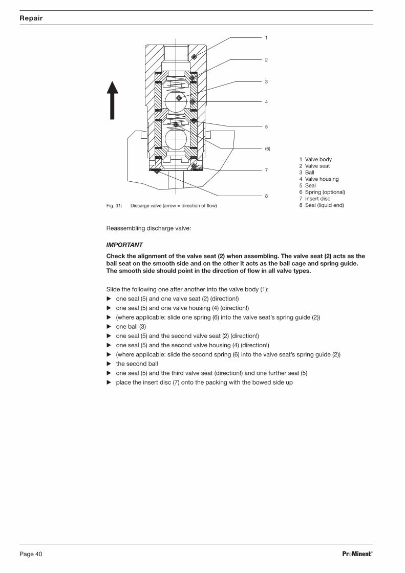
Reassembling discharge valve:
IMPORTANT
Check the alignment of the valve seat (2) when assembling. The valve seat (2) acts as theball seat on the smooth side and on the other it acts as the ball cage and spring guide.The smooth side should point in the direction of flow in all valve types.
Slide the following one after another into the valve body (1):
one seal (5) and one valve seat (2) (direction!)
one seal (5) and one valve housing (4) (direction!)
(where applicable: slide one spring (6) into the valve seat’s spring guide (2))
one ball (3)
one seal (5) and the second valve seat (2) (direction!)
one seal (5) and the second valve housing (4) (direction!)
(where applicable: slide the second spring (6) into the valve seat’s spring guide (2))
the second ball
one seal (5) and the third valve seat (direction!) and one further seal (5)
place the insert disc (7) onto the packing with the bowed side up
2
1
3
8
(6)
5
7
4
Fig. 31: Discarge valve (arrow = direction of flow)
1 Valve body2 Valve seat3 Ball4 Valve housing5 Seal6 Spring (optional)7 Insert disc8 Seal (liquid end)
BA_MA_TZ_006_10_06_GB.p65 05.02.2007, 13:41 Uhr40
ProMinent® Page 41
IMPORTANT
The distance between the edge of the ball body and the insert disc depends on the design.
Lay the large seal (8) between the insert disc (7) and the liquid end
Screw the valve up to the stop.
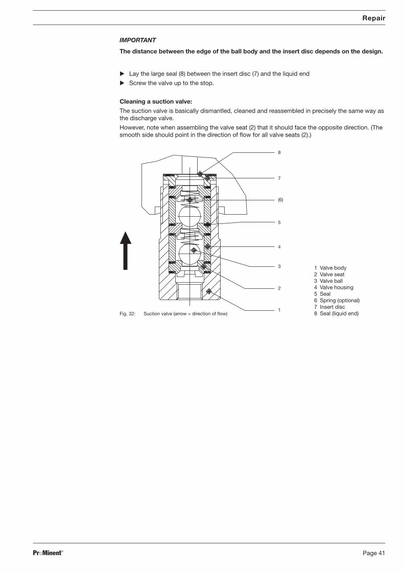
Cleaning a suction valve:
The suction valve is basically dismantled, cleaned and reassembled in precisely the same way asthe discharge valve.
However, note when assembling the valve seat (2) that it should face the opposite direction. (Thesmooth side should point in the direction of flow for all valve seats (2).)
Repair
7
8
(6)
1
3
4
2
5
Fig. 32: Suction valve (arrow = direction of flow)
1 Valve body2 Valve seat3 Valve ball4 Valve housing5 Seal6 Spring (optional)7 Insert disc8 Seal (liquid end)
BA_MA_TZ_006_10_06_GB.p65 05.02.2007, 13:41 Uhr41
ProMinent®Page 42
Repair
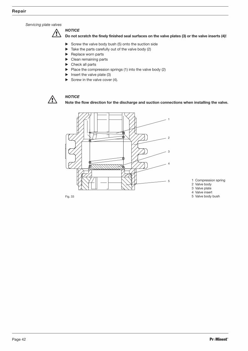
Servicing plate valves
NOTICE
Do not scratch the finely finished seal surfaces on the valve plates (3) or the valve inserts (4)!
Screw the valve body bush (5) onto the suction side Take the parts carefully out of the valve body (2) Replace worn parts Clean remaining parts Check all parts Place the compression springs (1) into the valve body (2) Insert the valve plate (3) Screw in the valve cover (4).
NOTICE
Note the flow direction for the discharge and suction connections when installing the valve.
2
1
3
4
Fig. 33
1 Compression spring2 Valve body3 Valve plate4 Valve insert5 Valve body bush
5
BA_MA_TZ_006_10_06_GB.p65 05.02.2007, 13:41 Uhr42
ProMinent® Page 43
Troubleshooting
12 Troubleshooting
WARNING
• EX pump only: Always observe the “Important supplements for dosing pumps inEX areas” section of the “General Operating Instruction for ProMinent® Motor-DrivenMetering Pumps and Hydraulic Accessories”!
• Metering pumps and their peripherals must be maintained and repaired by qualified orauthorised personnel.
• For all dosing pumps for dosing flammable media, the following applies: start up anddraining only under specialist supervision.
• Always depressurise the suction and discharge lines before working on the pump!
• Always empty and rinse the liquid end before maintenance or repair work if the pumphas been used with unknown or hazardous media.
• Always wear suitable protective equipment to work on the liquid end when the pump hasbeen used with hazardous or unknown media.
• Ensure that the pump cannot be switched on by unauthorized personnel before workingon the motor.
The pump does not prime despite full stroke action and bleeding
Cause: Valve dirty/worn
Remedy: Service valve (see “Repair” section)
Pump does not reach high pressure
Cause: Valve dirty/worn
Remedy: Service valve (see “Repair” section)
Cause: Motor connected incorrectly
Remedy: 1. Check voltage and frequency2. Reconnect motor correctly
Cause: Power supply failure
Remedy: Remedy cause
Cause: Composite diaphragm ruptured without initiating alarmRemedy: 1. Replace composite diaphragm without delay (see “Changing the diaphragm” in the
“Maintenance” section.)2. TZMb only: change the separating diaphragm of the diaphragm rupture sensor ifnecessary (see “Renewing the diaphragm rupture sensor separating diaphragm” in the“Repair” section.)
Diaphragm rupture indicator gives alarm
Cause: Composite diaphragm ruptured
Remedy: 1. Replace composite diaphragm without delay (see “Changing the diaphragm” in the“Maintenance” section.)2. TZMb only: change the separating diaphragm of the diaphragm rupture sensor ifnecessary (see “Renewing the diaphragm rupture sensor separating diaphragm” in the“Repair” section.)
TZHa only: No hydraulic oil is flowing through the hose on the vent valve
Cause: ---
Remedy: Shut the pump down immediately and inform customer service!
Drive motor very hot
Cause: Discharge line severely constricted
Remedy: Remove restriction from discharge line
BA_MA_TZ_006_10_06_GB.p65 05.02.2007, 13:41 Uhr43
ProMinent®Page 44
13 Decommissioning and disposal
Decommissioning
WARNING
• EX pump only: Always observe the “Important supplements for dosing pumps inEX areas” section of the “General Operating Instruction for ProMinent® Motor-DrivenMetering Pumps and Hydraulic Accessories”!
• Metering pumps and their peripherals must be decommissioned by qualified orauthorised personnel.
• For all dosing pumps for dosing flammable media, the following applies: start up anddraining only under specialist supervision.
• When the pump is taken out of service, the pump housing and especially the liquid endmust be thoroughly cleansed of chemicals and dirt!
• Always depressurise the discharge and suction line first before working on the pump!
• When hazardous or unknown media are used, suitable protective equipment must beworn when working on the liquid end.
• Isolate the supply before working on the motor!
• If an external fan, speed control or diaphragm rupture sensor are provided, isolate theseas well!
Check that no voltage is present!
• Always secure the supply against unauthorised reconnection during work on the pump!
Final decommissioning Disconnect pump from mains
Rinse out the liquid end with a suitable rinse aid, rinse thoroughly if used with hazardousmaterials
Drain out gear oil
TZHa: drain out hydraulic oil (2 drain plugs!)
Temporary decommissioning also:
Attach caps to valves
Place hose nozzle caps on hose nozzles
Ideally place the pump on a pallet
Cover the pump with a tarpaulin (allow ventilation from the back!).
Store pump in a dry, closed warehouse at
storage temperature -10 °C to 50 °Chumidity max. 95 % rel. humidity, non-condensing
Disposal
NOTICE
Observe all currently applicable local directives!(particularly with regard to oils)
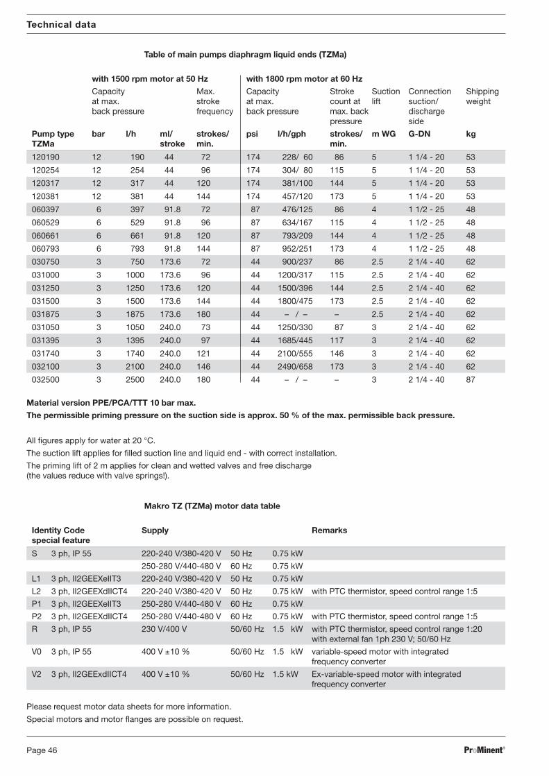
P2 3 ph, II2GEEXdIICT4 250-280 V/440-480 V 60 Hz 0.75 kW with PTC thermistor, speed control range 1:5
R 3 ph, IP 55 230 V/400 V 50/60 Hz 1.5 kW with PTC thermistor, speed control range 1:20with external fan 1ph 230 V; 50/60 Hz
V0 3 ph, IP 55 400 V ±10 % 50/60 Hz 1.5 kW variable-speed motor with integratedfrequency converter
V2 3 ph, II2GEExdIICT4 400 V ±10 % 50/60 Hz 1.5 kW Ex-variable-speed motor with integratedfrequency converter
Please request motor data sheets for more information.Special motors and motor flanges are possible on request.
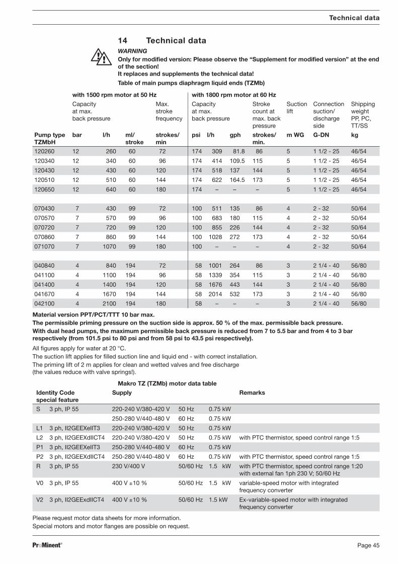
14 Technical dataWARNINGOnly for modified version: Please observe the “Supplement for modified version” at the endof the section!It replaces and supplements the technical data!
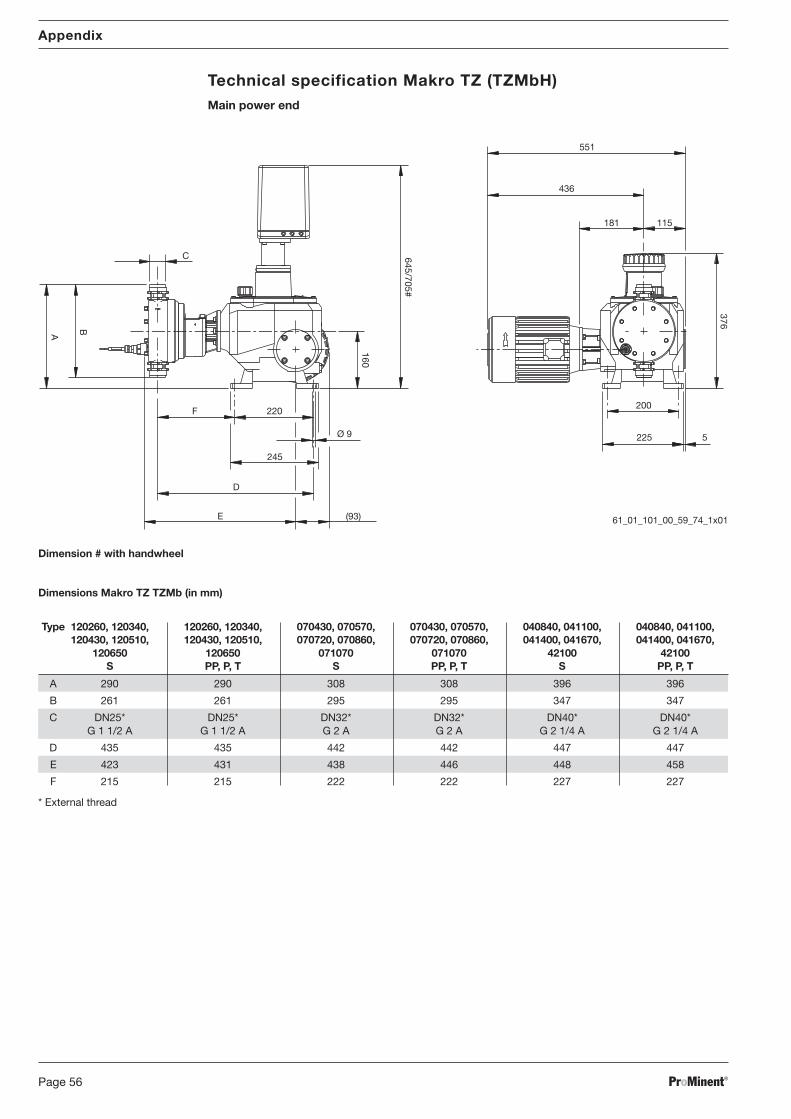
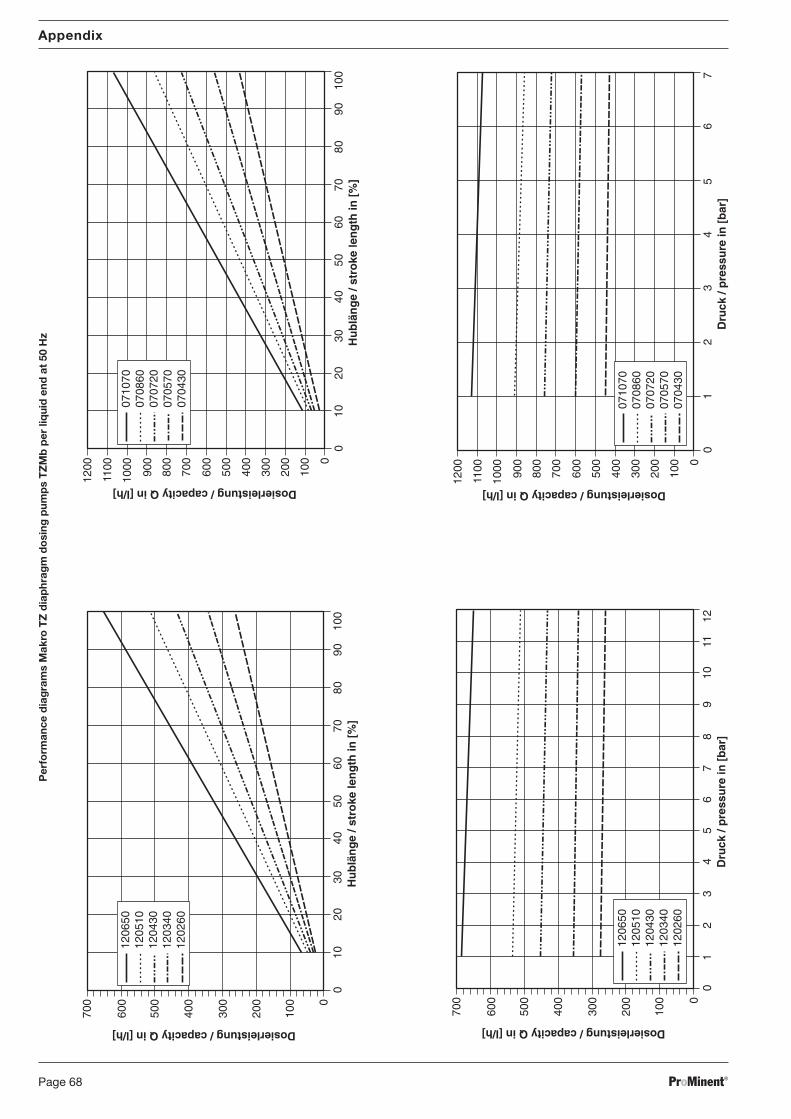
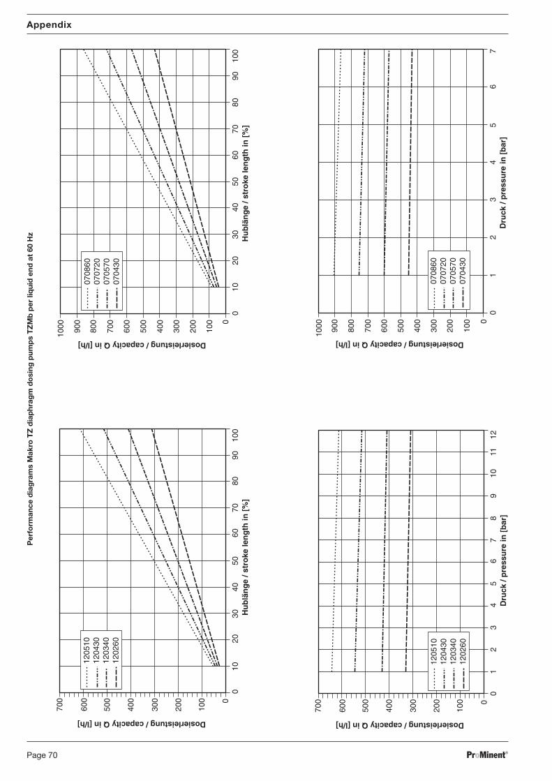
Table of main pumps diaphragm liquid ends (TZMb)
with 1500 rpm motor at 50 Hz with 1800 rpm motor at 60 Hz
Capacity Max. Capacity Stroke Suction Connection Shippingat max. stroke at max. count at lift suction/ weightback pressure frequency back pressure max. back discharge PP, PC,
pressure side TT/SS
Pump type bar l/h ml/ strokes/ psi l/h gph strokes/ m WG G-DN kgTZMbH stroke min min.
Material version PPT/PCT/TTT 10 bar max.The permissible priming pressure on the suction side is approx. 50 % of the max. permissible back pressure.With dual head pumps, the maximum permissible back pressure is reduced from 7 to 5.5 bar and from 4 to 3 barrespectively (from 101.5 psi to 80 psi and from 58 psi to 43.5 psi respectively).
All figures apply for water at 20 °C.The suction lift applies for filled suction line and liquid end - with correct installation.The priming lift of 2 m applies for clean and wetted valves and free discharge(the values reduce with valve springs!).
P2 3 ph, II2GEEXdIICT4 250-280 V/440-480 V 60 Hz 0.75 kW with PTC thermistor, speed control range 1:5
R 3 ph, IP 55 230 V/400 V 50/60 Hz 1.5 kW with PTC thermistor, speed control range 1:20with external fan 1ph 230 V; 50/60 Hz
V0 3 ph, IP 55 400 V ±10 % 50/60 Hz 1.5 kW variable-speed motor with integratedfrequency converter
V2 3 ph, II2GEExdIICT4 400 V ±10 % 50/60 Hz 1.5 kW Ex-variable-speed motor with integratedfrequency converter
Please request motor data sheets for more information.
Special motors and motor flanges are possible on request.
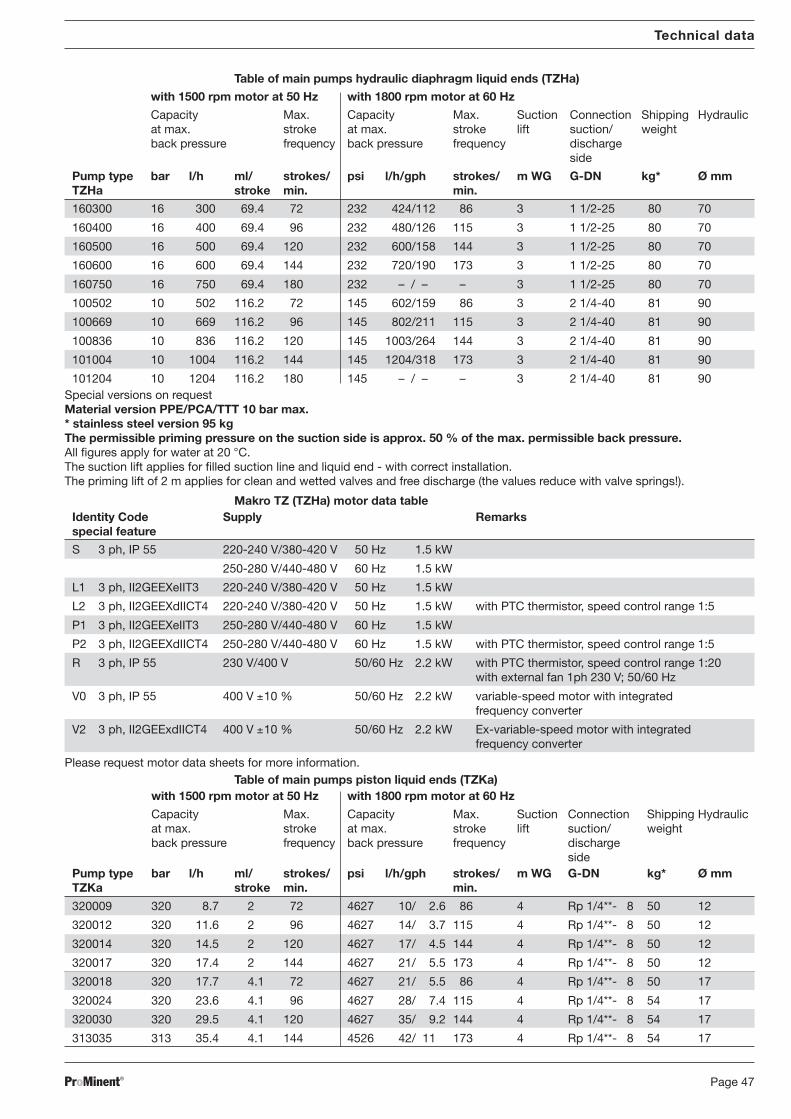
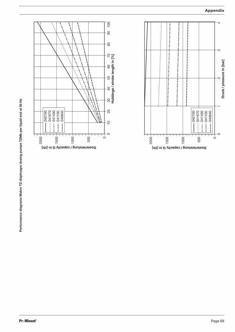
Table of main pumps diaphragm liquid ends (TZMa)
with 1500 rpm motor at 50 Hz with 1800 rpm motor at 60 Hz
Capacity Max. Capacity Stroke Suction Connection Shippingat max. stroke at max. count at lift suction/ weightback pressure frequency back pressure max. back discharge
pressure side
Pump type bar l/h ml/ strokes/ psi l/h/gph strokes/ m WG G-DN kgTZMa stroke min. min.
101204 10 1204 116.2 180 145 – / – – 3 2 1/4-40 81 90Special versions on requestMaterial version PPE/PCA/TTT 10 bar max.* stainless steel version 95 kgThe permissible priming pressure on the suction side is approx. 50 % of the max. permissible back pressure.All figures apply for water at 20 °C.The suction lift applies for filled suction line and liquid end - with correct installation.The priming lift of 2 m applies for clean and wetted valves and free discharge (the values reduce with valve springs!).
Makro TZ (TZHa) motor data tableIdentity Code Supply Remarksspecial feature
011951 11 951.1 110 144 160 1141/301 173 4 2 1/4- 40 68 85** The Rp 1/4 and Rp 3/8 suction and discharge side connections have female threaded connections and are constructed as
double ball valves.The permissible priming pressure on the suction side is approx. 50 % of the max. permissible back pressure.ll figures apply for water at 20 °C.The suction lift applies for filled suction line and liquid end - with correct installation.The priming lift of 2 m applies for clean and wetted valves and free discharge(the values reduce with valve springs!).
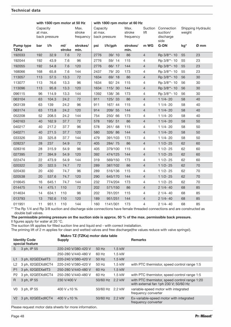
with 1500 rpm motor at 50 Hz with 1800 rpm motor at 60 Hz
Capacity Max. Capacity Max. Suction Connection Shipping Hydraulicat max. stroke at max. stroke lift suction/ weightback pressure frequency back pressure frequency discharge
sidePump type bar l/h ml/ strokes/ psi l/h/gph strokes/ m WG G-DN kg* Ø mmTZKa stroke min. min.
Makro TZ (TZKa) motor data tableIdentity Code Supply Remarksspecial featureS 3 ph, IP 55 220-240 V/380-420 V 50 Hz 1.5 kW
P2 3 ph, II2GEEXdIICT4 250-280 V/440-480 V 60 Hz 1.5 kW with PTC thermistor, speed control range 1:5
R 3 ph, IP 55 230 V/400 V 50/60 Hz 2.2 kW with PTC thermistor, speed control range 1:20with external fan 1ph 230 V; 50/60 Hz
V0 3 ph, IP 55 400 V ±10 % 50/60 Hz 2.2 kW variable-speed motor with integratedfrequency converter
V2 3 ph, II2GEExdIICT4 400 V ±10 % 50/60 Hz 2.2 kW Ex-variable-speed motor with integratedfrequency converter
Please request motor data sheets for more information.
BA_MA_TZ_006_10_06_GB.p65 05.02.2007, 13:41 Uhr48
ProMinent® Page 49
Technical data
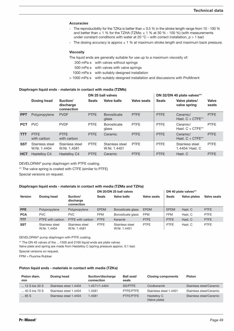
Accuracies
- The reproducibility for the TZKa is better than ± 0.5 % in the stroke length range from 10 - 100 %and better than ± 1 % for the TZHA (TZMa: ± 1 % at 30 % - 100 %) (with measurementsunder constant conditions with water at 20 °C – with correct installation, p > 1 bar)
- The dosing accuracy is approx ± 1 % at maximum stroke length and maximum back pressure.
Viscosity
The liquid ends are generally suitable for use up to a maximum viscosity of: 200 mPa s with valves without springs 500 mPa s with valves with valve springs1000 mPa s with suitably designed installation
> 1000 mPa s with suitably designed installation and discussions with ProMinent
Diaphragm liquid ends - materials in contact with media (TZMb)
DN 25 ball valves DN 32/DN 40 plate valves**
Dosing head Suction/ Seals Valve balls Valve seats Seals Valve plates/ Valvedischarge valve spring seatsconnection
** The DN 40 valves of the …1500 and 2100 liquid ends are plate valves.Valve plate and spring are made from Hastelloy C (spring pressure approx. 0.1 bar)
Special versions on request.
FPM = Fluorine Rubber
BA_MA_TZ_006_10_06_GB.p65 05.02.2007, 13:41 Uhr49
ProMinent®Page 50
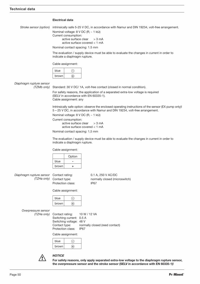
Electrical data
Stroke sensor (option) intrinsically safe 5-25 V DC, in accordance with Namur and DIN 19234, volt-free arrangement.
Nominal voltage: 8 V DC (Ri ~ 1 kΩ)Current consumption:
active surface clear > 3 mAactive surface covered < 1 mA
Nominal contact spacing: 1.5 mm
The evaluation / supply device must be able to evaluate the changes in current in order toindicate a diaphragm rupture.
Cable assignment:
blue -
brown +
Diaphragm rupture sensor(TZMb only) Standard: 30 V DC/ 1A, volt-free contact (closed in normal condition).
For safety reasons, the application of a separated extra-low voltage is required(SELV in accordance with EN 60335-1).Cable assignment: any
Intrinsically safe option: observe the enclosed operating instructions of the sensor (EX pump only)!5 – 25 V DC, in accordance with Namur and DIN 19234, volt-free arrangement.
Nominal voltage: 8 V DC (Ri ~ 1 kΩ)
Current consumption:active surface clear > 3 mAactive surface covered < 1 mA
Nominal contact spacing: 1,5 mm
The evaluation / supply device must be able to evaluate the changes in current in order toindicate a diaphragm rupture.
Cable assignment:
Option
blue -
brown +
Diaphragm rupture sensor Contact rating: 0.1 A, 250 V AC/DC(TZHa only) Contact type: normally closed (microswitch)
Protection class: IP67
Cable assignment:
blue -
brown +
Overpressure sensor(TZHa only) Contact rating: 10 W / 12 VA
For safety reasons, only apply separated extra-low voltage to the diaphragm rupture sensor,the overpressure sensor and the stroke sensor (SELV in accordance with EN 60335-1)!
Technical data
on).
e is required
ns of the sensor
arrangement.
es in current in order to
lly!
r the diaphragm rupturehed off after a diaphragm
BA_MA_TZ_006_10_06_GB.p65 05.02.2007, 13:41 Uhr50
ProMinent® Page 51
Piston liquid ends Material long term at max. back pressure(TZKa)
Stainless steel 150 °C
Technical data
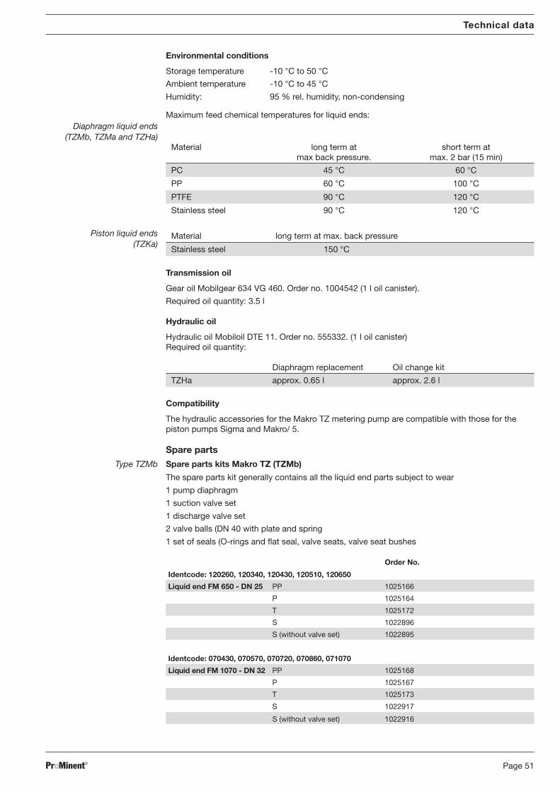
Environmental conditions
Storage temperature -10 °C to 50 °C
Ambient temperature -10 °C to 45 °C
Humidity: 95 % rel. humidity, non-condensing
Maximum feed chemical temperatures for liquid ends:Diaphragm liquid ends
(TZMb, TZMa and TZHa)Material long term at short term at
max back pressure. max. 2 bar (15 min)
PC 45 °C 60 °C
PP 60 °C 100 °C
PTFE 90 °C 120 °C
Stainless steel 90 °C 120 °C
Transmission oil
Gear oil Mobilgear 634 VG 460. Order no. 1004542 (1 l oil canister).
Required oil quantity: 3.5 l
Hydraulic oil
Hydraulic oil Mobiloil DTE 11. Order no. 555332. (1 l oil canister)Required oil quantity:
Diaphragm replacement Oil change kit
TZHa approx. 0.65 l approx. 2.6 l
Compatibility
The hydraulic accessories for the Makro TZ metering pump are compatible with those for thepiston pumps Sigma and Makro/ 5.
Spare partsType TZMb Spare parts kits Makro TZ (TZMb)
The spare parts kit generally contains all the liquid end parts subject to wear
1 pump diaphragm
1 suction valve set
1 discharge valve set
2 valve balls (DN 40 with plate and spring
1 set of seals (O-rings and flat seal, valve seats, valve seat bushes
Order No.
Identcode: 120260, 120340, 120430, 120510, 120650
Liquid end FM 650 - DN 25 PP 1025166
P 1025164
T 1025172
S 1022896
S (without valve set) 1022895
Identcode: 070430, 070570, 070720, 070860, 071070
Liquid end FM 1070 - DN 32 PP 1025168
P 1025167
T 1025173
S 1022917
S (without valve set) 1022916
BA_MA_TZ_006_10_06_GB.p65 05.02.2007, 13:41 Uhr51
ProMinent®Page 52
Technical data
Identcode: 040840, 041100, 041400, 041670, 042100
Liquid end FM 2100 - DN 40 PP 1025170
Fördereinheit P 1025169
T 1025174
S 1022930
S (without valve set) 1022929
PTFE compos i te pump d iaphragm fo r TZMbProMinent® DEVELOPAN® pump diaphragm made from EPDM with a woven inlay, generous integrally vulcanisedsteel core and PTFE Teflon coating on the surface in contact with the medium.
Description for pump type Order No.
Identcode: 120260, 120340, 120430, 120510, 120650Makro TZ FM 650 1022887
Identcode: 070430, 070570, 070720, 070860, 071070Makro TZ FM 1070 1022900
PTFE pump d iaphragmProMinent® DEVELOPAN® pump diaphragm made from EPDM with a woven inlay, generous integrally vulcanisedsteel core and PTFE Teflon coating on the surface in contact with the medium.
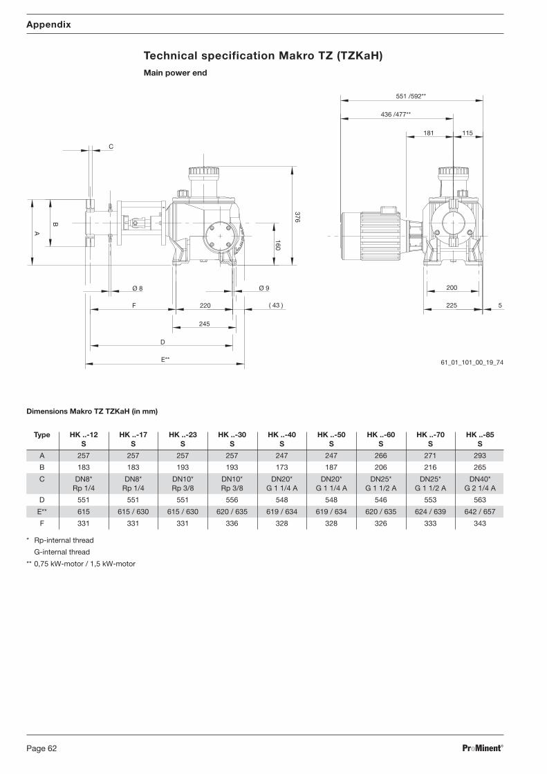
Technical specification Makro TZ (TZKaH)Main power end
61_01_101_00_19_74
Ø 8
F
D
E**
220
245
Ø 9
( 43 )
A
B
C
160
376
551 /592**
436 /477**
181 115
200
225 5
BA_MA_TZ_006_10_06_GB.p65 05.02.2007, 13:41 Uhr62
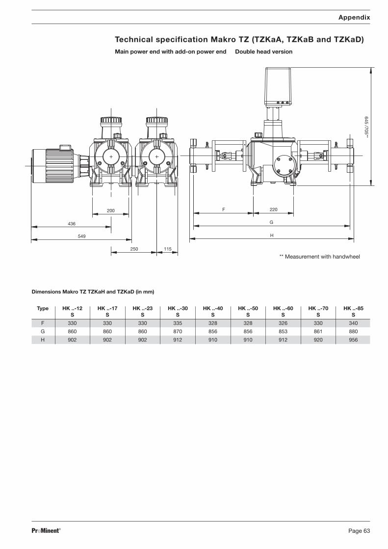
ProMinent® Page 63
Dimensions Makro TZ TZKaH and TZKaD (in mm)
Type HK ..-12 HK ..-17 HK ..-23 HK ..-30 HK ..-40 HK ..-50 HK ..-60 HK ..-70 HK ..-85S S S S S S S S S
F 330 330 330 335 328 328 326 330 340
G 860 860 860 870 856 856 853 861 880
H 902 902 902 912 910 910 912 920 956
Appendix
Technical specification Makro TZ (TZKaA, TZKaB and TZKaD)Main power end with add-on power end Double head version
** Measurement with handwheel
436
549
200
250 115
G
F 220
H
645 /705**
BA_MA_TZ_006_10_06_GB.p65 05.02.2007, 13:41 Uhr63
ProMinent®Page 64
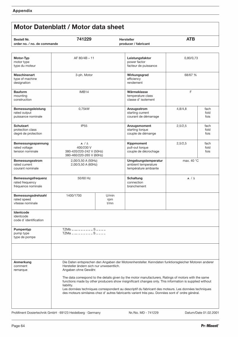
Appendix
Motor Datenblatt / Motor data sheet
Bestell Nr. 741229 Hersteller ATBorder no. / no. de commande producer / fabricant
Motor-Typ AF 80/4B – 11 Leistungsfaktor 0,80/0,73motor type power factortype du moteur facteur de puissance
Maschinenart 3-ph. Motor Wirkungsgrad 68/67 %type of machine efficiencydesignation rendement
Bauform IMB14 Wärmeklasse Fmounting temperature classconstruction classe d’ isolement
Bemessungsleistung 0,75kW Anzugsstrom 4,8/4,8 fachrated output starting current foldpuissance nominale courant de démarrage fois
Schutzart IP55 Anzugsmoment 2,5/2,5 fachprotection class starting torque folddegré de protection couple de démarrge fois
Bemessungsspannung / ∆ Kippmoment 2,5/2,5 fachrated voltage 400/230 V pull-out torque foldtension nominale 380-420/220-242 V (50Hz) couple de décrochage fois
380-460/220-265 V (60Hz)
Bemessungsstrom 2,00/3,50 A (50Hz) Umgebungstemperatur max. 40 °Crated current 2,00/3,50 A (60Hz) ambient temperaturecourant nominale température ambiante
Bemessungsfrequenz 50/60 Hz Schaltung / ∆rated frequency connectionfréquence nominale branchement
Pumpentyp TZMb – –– – – – – – – S – – – –pump type TZMa – –– – – – – – – S – – – –type de pompe
Anmerkung Die Daten entsprechen den Angaben der Motorenhersteller. Kenndaten funktionsgleicher Motoren anderercomment Hersteller ändern sich nur unwesentlich.remarque Angaben ohne Gewähr.
The data correspond to the details given by the motor manufacturers. Ratings of motors with the samefunctions made by other producers show insignificant changes only. This information is supplied withoutliability.Les données techniques correspondent au descriptif du fabricant des moteurs. Les données techniquesdes moteurs similaires chez d’ autres fabricants varient très peu. Données sont d’ ordre général.
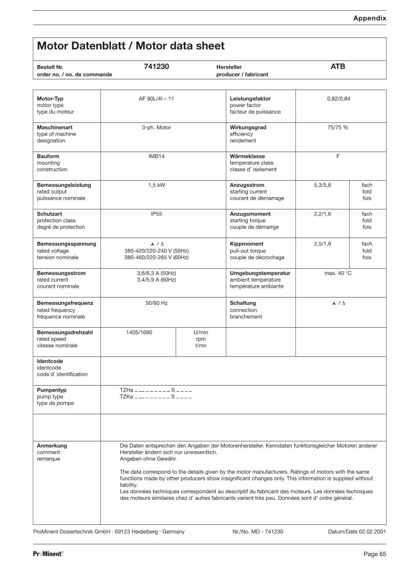
Bestell Nr. 741230 Hersteller ATBorder no. / no. de commande producer / fabricant
Motor-Typ AF 90L/4I – 11 Leistungsfaktor 0,82/0,84motor type power factortype du moteur facteur de puissance
Maschinenart 3-ph. Motor Wirkungsgrad 75/75 %type of machine efficiencydesignation rendement
Bauform IMB14 Wärmeklasse Fmounting temperature classconstruction classe d’ isolement
Bemessungsleistung 1,5 kW Anzugsstrom 5,3/5,8 fachrated output starting current foldpuissance nominale courant de démarrage fois
Schutzart IP55 Anzugsmoment 2,2/1,6 fachprotection class starting torque folddegré de protection couple de démarrge fois
Bemessungsspannung / ∆ Kippmoment 2,5/1,9 fachrated voltage 380-420/220-240 V (50Hz) pull-out torque foldtension nominale 380-460/220-265 V (60Hz) couple de décrochage fois
Bemessungsstrom 3,6/6,3 A (50Hz) Umgebungstemperatur max. 40 °Crated current 3,4/5,9 A (60Hz) ambient temperaturecourant nominale température ambiante
Bemessungsfrequenz 50/60 Hz Schaltung / ∆rated frequency connectionfréquence nominale branchement
Pumpentyp TZHa – –– – – – – – – S – – – –pump type TZKa – –– – – – – – – S – – – –type de pompe
Anmerkung Die Daten entsprechen den Angaben der Motorenhersteller. Kenndaten funktionsgleicher Motoren anderercomment Hersteller ändern sich nur unwesentlich.remarque Angaben ohne Gewähr.
The data correspond to the details given by the motor manufacturers. Ratings of motors with the samefunctions made by other producers show insignificant changes only. This information is supplied withoutliability.Les données techniques correspondent au descriptif du fabricant des moteurs. Les données techniquesdes moteurs similaires chez d’ autres fabricants varient très peu. Données sont d’ ordre général.
Vertretungen weltweit / Distributors WorldwideArgentina · Bahrain · Bolivia · Botswana · Chile · Columbia · Costa Rica · Croatia · Cuba · Cyprus · Denmark · Egypt · El Salvador · Guatemala · Hong Kong ·Indonesia · Iceland · Iran · Ireland · Israel · Jordan · Kenya · Kuwait · Macedonia · Malta · Namibia · New Zealand · Nigeria · Norway · Oman · Pakistan · Panama ·Paraguay · Peru · Philippines · Qatar · Romania · Russia-Ural Region · Saudi Arabia · Senegal · Serbia/Montenegro · Slovenia · Sudan · Syria · Tanzania · Tunisia ·Turkey · Turkmenistan · Uganda · Uruguay · United Arab Emirates · Venezuela · Vietnam · White Russia · Zimbabwe
Anschriftennachweise erhalten Sie durch: / Addresses of distributors are available from: ProMinent Dosiertechnik GmbH, Germany