Operating instructions Date: 20.02.06 Ident. no.: Serial no.: Contents 0. Brief instructions 1. General Application 2. Safety 3. Transportation and temporary storage Preservation 4. Description Structural design 5. Planning the system Pipes, safety equipment 6. Installing the pump Safety measures 7. Start-up / shut-down 8. Maintenance 9. Servicing, disassembly, reassembly Spare parts, standby pumps 10. Faults; causes and correction 11. Associated documents 12. Pump identification This pump may only be installed and brought into service by trained personnel, who must precisely follow these operating instructions and the applicable legal requirements. If these operating instructions are not followed: you may be putting yourself or your colleagues at risk, the pump or the pump unit may be damaged, and the manufacturer will not be liable for any resulting damage! When working on the pump or pump unit, please remember that you are responsible for the safety of your colleagues! These operating instructions conform to the provisions of EN292 part 2, sub-section 5.5 and the safety regulation EN809. SRZS...W Shaft sealing: G11/G12/G13 Material code: 32
This pump may only be installed and brought intoservice by trained personnel, who must precisely follow theseoperating instructions and the applicable legal requirements.If these operating instructions are not followed:you may be putting yourself or your colleagues at risk,the pump or the pump unit may be damaged,and the manufacturer will not be liable for any resultingdamage!When working on the pump or pump unit, please rememberthat you are responsible for the safety of your colleagues!
These operating instructions conform to theprovisions of EN292 part 2, sub-section 5.5 and the safetyregulation EN809.
0. Brief instructions on starting up a pump unit supplied complete� The pumped liquids must not have a tendency to crystallise out and must contain no potentially abrasive solids
(see section 1.1 Application).
� Remove the protective caps from the pipe sockets before connecting the pipes.
� If the pump has been preserved, drain off the preservative agent (dispose of correctly) and clean the pump.
� Align the pump or pump unit on the foundation and fix in place.
� Clean the pipes.� Note the directions of flow and rotation (see arrows on the pump).
� Fill the pump with liquid (the pump must have been thoroughly vented).
� Open all the shut-off devices in the inlet and discharge pipes.� Check that the coupling guard is fitted and all the safety equipment is ready for operation.
� Fit a motor circuit-breaker. The electrical connection work may only be carried out by a qualified electrician.Check the voltage, speed and direction of rotation.
� Turn the unit manually and ensure that it is running smoothly and evenly.
� Switch on the motor.� Once it has run up to operational speed, check the operating pressure on the manometer and set the operating
point by restricting the pressure on the discharge side, if necessary.
� Do not allow the flow to fall below the minimum value.
� The pump must be constantly supplied with fluid. It must never be allowed to run dry.
� Never touch a pump while it is running - it may be hot/cold.
� The power consumption increases as the pump head rises and the amount of liquid pumped decreases.
� The pump must never be started up or operated when the inlet and/or discharge pipe is closed.� During assembly or operation, the pipes must not transmit stresses to the pump.
The safety instructions specified under point 2-ff must be followed.
k01v0001.ENG
02.10.95
1. General
1.1 ApplicationThis is a self-priming side channel pump. It is suitable for pumpingpure, cloudy and gaseous liquids containing no abrasives (size notlarger than 0,1 mm).In design, it corresponds to a multistage ring section pump. The useof standardised components for several pump series and sizesmakes it economical to keep a stock of standby parts and topurchase spare parts. The pump is driven by an electric motor.The pump should be used only under the operating conditionsspecified by the customer and confirmed by the supplier. The correctand intended application is specified in the data sheet supplied withthe pump, a copy of which is shown in the appendix.
The pump must only be used for the applicationspecified in the data sheet. Otherwise, it may endanger bothpeople and the environment.Do not allow the specific gravity to fall below or exceed thevalue specified in the data sheet, since this could result indamage to the pump.
Systems in which a failure or malfunction could leadto injury or damage should be fitted with alarm systems and/orstandby units and should be checked at regular intervals toensure that they are in good working order.Units which are directly or indirectly linked to drinking watersupplies should be thoroughly cleaned before installation andstart-up to remove all impurities.
Never touch a pump while it is in use - it may be hot.The data relating to speed, pressure and temperature contained inthe data sheet are values at which correct functioning of the pump isguaranteed. It is essential to adhere to these values.
If the outlet side of a pump is closed while the pumpis running, the temperature of the liquid in the pump may rise toa dangerous degree. Dangers may arise from overpressure andsubsequent failure of part of the pump or pipework. Particulardangers arise if the liquid being pumped is flammable, as it willbe more easily ignited at increased temperatures. Explosionsmay occur if the liquid is chemically unstable when overheated.These dangers are commonly prevented by providing a liquidreturn loop incorporating a pressure relief valve.It is also important not to fall below the specified inlet pressures(system pressures). If the order confirmation does not specify anypressures and/or temperatures, then the limit pressures andtemperatures specified in the brochure apply, provided that no furtherrestrictions are imposed by the type of shaft seal used.
1.2 TestingAll our pumps undergo extensive testing on the test bench beforethey leave the factory.Only pumps which are running perfectly and achieve the promisedperformance levels, taking account of the specified tolerances, areallowed to leave the factory. If these operating instructions arefollowed, we guarantee fault-free operation and full pumping capacity.
Test pressure = 1.5 x pump operating pressure
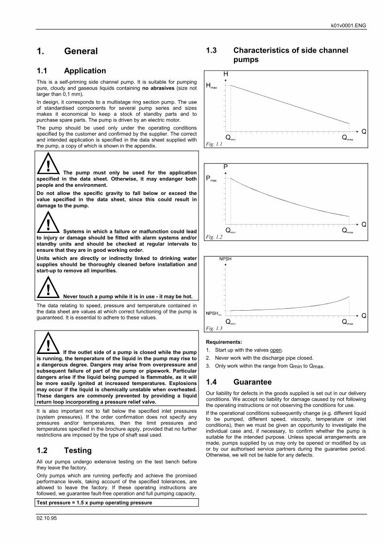
1.3 Characteristics of side channelpumps
Requirements:1. Start up with the valves open.2. Never work with the discharge pipe closed.3. Only work within the range from Qmin to Qmax.
1.4 GuaranteeOur liability for defects in the goods supplied is set out in our deliveryconditions. We accept no liability for damage caused by not followingthe operating instructions or not observing the conditions for use.If the operational conditions subsequently change (e.g. different liquidto be pumped, different speed, viscosity, temperature or inletconditions), then we must be given an opportunity to investigate theindividual case and, if necessary, to confirm whether the pump issuitable for the intended purpose. Unless special arrangements aremade, pumps supplied by us may only be opened or modified by usor by our authorised service partners during the guarantee period.Otherwise, we will not be liable for any defects.
Fig. 1.1
Fig. 1.2
Fig. 1.3
k01v0001.ENG
02.10.95
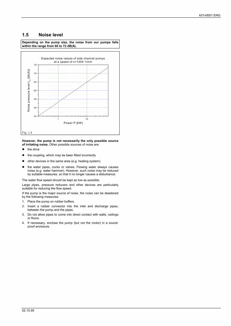
1.5 Noise levelDepending on the pump size, the noise from our pumps fallswithin the range from 60 to 72 dB(A).
However, the pump is not necessarily the only possible sourceof irritating noise. Other possible sources of noise are:� the drive
� the coupling, which may be been fitted incorrectly
� other devices in the same area (e.g. heating system)
� the water pipes, cocks or valves. Flowing water always causesnoise (e.g. water hammer). However, such noise may be reducedby suitable measures, so that it no longer causes a disturbance.
The water flow speed should be kept as low as possible.Large pipes, pressure reducers and other devices are particularlysuitable for reducing the flow speed.If the pump is the major source of noise, the noise can be deadenedby the following measures:1. Place the pump on rubber buffers.2. Insert a rubber connector into the inlet and discharge pipes,
between the pump and the pipes.3. Do not allow pipes to come into direct contact with walls, ceilings
or floors.4. If necessary, enclose the pump (but not the motor) in a sound-
proof enclosure.
1 1045
50
55
60
65
70
75
Expected noise values of side channel pumpsat a speed of n=1450 1/min
Noi
se p
ress
ure
leve
l LA [d
b(A
)]
Power P [kW]
Fig. 1.4
k02v0001.ENG
02.10.95
2. SafetyThese operating instructions contain fundamental information whichmust be followed during installation, operation and maintenance.Consequently, before assembly and start-up, these operatinginstructions must be read by the mechanic and the competenttechnical personnel / operators, and must be available at all times inthe vicinity of the machine / system.In addition to the safety instructions given in this section, the otherspecial safety instructions (e.g. for private use) given in othersections must also be followed. Local safety regulations will not besuperseded by these operating instructions.
2.1 Identification of instructions inthese operating instructions
If certain safety instructions in these operating instructions are notfollowed, there could be a risk to personal safety. These instructionsare identified by the general hazard symbol:
Safety symbol according to ISO 3864-B.3.1
In the case of warnings about electrical voltage, the safetyinstructions are identified by:
Safety symbol according to ISO 3864-B.3.6
For safety instructions which, if they are not followed, could endangerthe machine and its functioning, the word
WARNINGis inserted. Instructions attached to the machine, such as thedirection of rotation arrows or liquid connection markers, must befollowed and must be fully legible at all times.
2.2 Personnel qualifications andtraining
The operating, maintenance, inspection and assembly personnelmust have the appropriate qualifications for this work. The area ofresponsibility, competence and staff supervision must be preciselystipulated by the owner. If none of the personnel has the necessaryexperience or knowledge, then they must be given training andinstruction. If necessary, this can be provided by themanufacturer/supplier at the machine owner’s request. The machineowner should also ensure that the content of the operatinginstructions is fully understood by his employees.
2.3 Risks if the safety instructions arenot observed
Failure to observe the safety instructions can endanger people, theenvironment and the machine. Any claims for damages may beinvalidated if the safety instructions are not followed. Failuire toobserve the safety instructions can, for example, lead to thefollowing risks:� Failure of important machine/system functions
� Failure of prescribed maintenance and repair methods
� Lives may be put at risk by electrical, mechanical and chemicalhazards.
� Risk to the environment caused by the leaking of hazardousmaterials.
2.4 Safe working practicesThe safety instructions given in these operating instructions, theapplicable national accident prevention regulations and the owner’sinternal working, operational and safety regulations should befollowed.
2.5 Safety instructions for the owner /operator
� If hot or cold machine parts represent a potential risk, these partsmust be protected on site against accidental contact.
� Protective devices on moving parts to prevent accidental contact(e.g. coupling guard) must not be removed while the machine isin use.
� Leaks (e.g. from the shaft seal) of hazardous (e.g. explosive,poisonous, hot) liquids must be eliminated so that they do notendanger life or the environment. The legal regulations must beobserved.
� Measures should be taken to prevent the risk of electric shock(for further information on this subject, see the VDE regulationsand those of the local electricity company, for example).
2.6 Safety instructions formaintenance, inspection andassembly work
The owner must ensure that all maintenance, inspection andassembly work is carried out by authorised and qualified technicalstaff who have read and understood the operating instructions.Work must only be carried out when the machine is shut down. Theprocedure for shutting down the machine described in the operatinginstructions MUST be followed.Pumps or pump units containing media which are a potential hazardto health must be decontaminated. Pumps sent to us for repairshould be cleaned beforehand so that they do not represent a hazardto the health of our employees. As soon as the work has ended, allsafety and protective devices must be replaced or brought intoservice once more. Sections 7.1, 7.3 and 7.4.2 must be followedbefore starting up the machine again.
2.7 Conversion and production ofspare parts by the owner
The machine may not be converted or modified without themanufacturer’s prior approval. The use of original spare parts andaccessories authorised by the manufacturer ensure operationalsafety. The use of other parts may invalidate our liability for anyresulting damage.
2.8 Inadmissible operating methodsThe operational safety of the machine can only be guaranteed if it isused in the manner intended, as described in Section 1 General ofthese operating instructions. The limit values specified in the datasheet must not be exceeded under any circumstances.
K03V0002.ENG
02.10.95
3. Transportation and temporarystorage
3.1 Safety measures
Never stand beneath a suspended load.Always keep a safe distance from the load while it is beingmoved.Only use the prescribed lifting tools and ensure that they are inperfect condition.Adjust the length of the lifting devices so that the pump or unitis suspended horizontally.Do not remove any documents that are attached to the pump.Always handle the pump with care.
3.2 PackagingThe symbols on the packaging should be observed. The inlet anddischarge sides of the pump must be closed off with caps duringtransportation and storage. When installing the pump unit, the flangecaps should be removed.
3.3 UnpackingBefore unpacking, carry out a visual inspection of the packaging. Ifany damage has occurred during transportation, note the extent ofthe damage on the receipt or delivery note. Any claims should bemade immediately to the carrier company or carriage insurancecompany.
3.4 Temporary storageIf the pump or unit is not installed immediately upon delivery, themachine must be stored frost-free in a dry and vibration-free area.
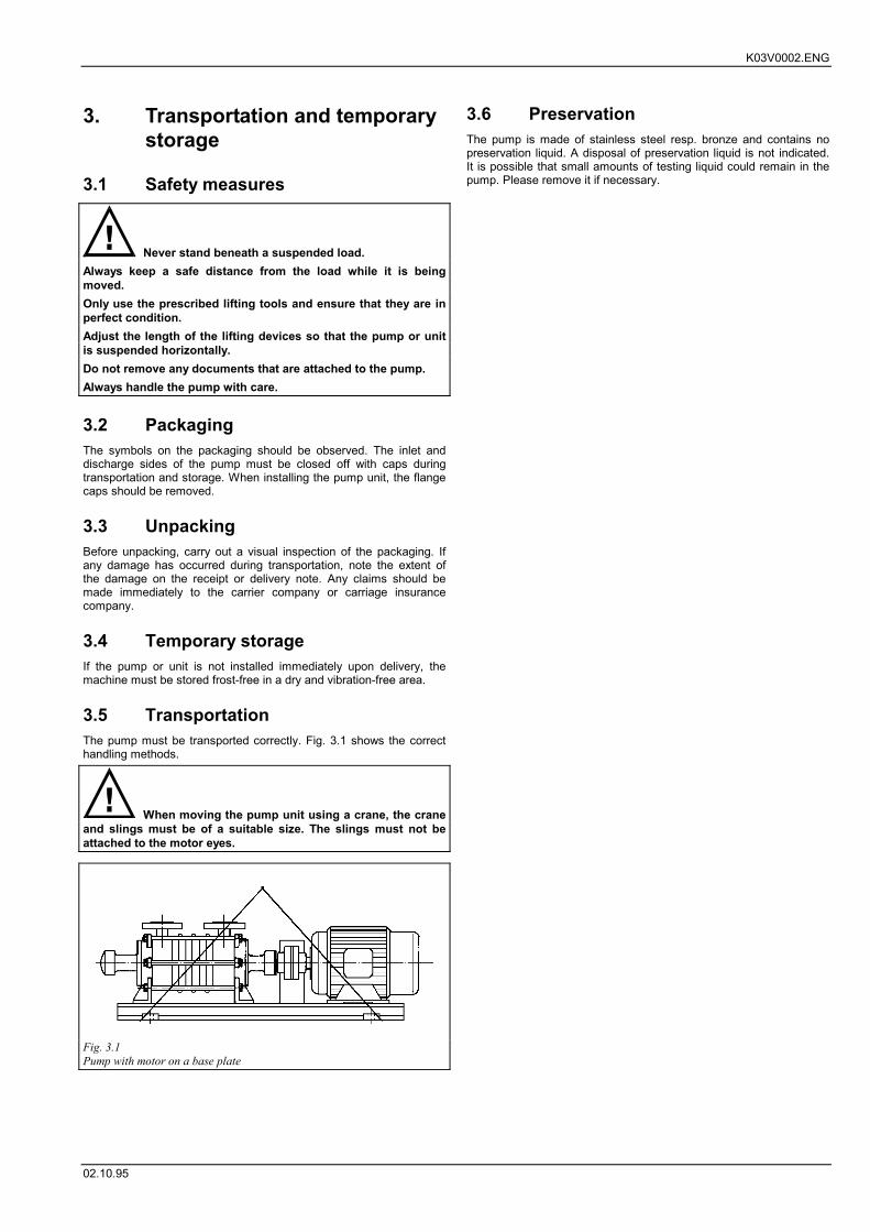
3.5 TransportationThe pump must be transported correctly. Fig. 3.1 shows the correcthandling methods.
When moving the pump unit using a crane, the craneand slings must be of a suitable size. The slings must not beattached to the motor eyes.
3.6 PreservationThe pump is made of stainless steel resp. bronze and contains nopreservation liquid. A disposal of preservation liquid is not indicated.It is possible that small amounts of testing liquid could remain in thepump. Please remove it if necessary.
Fig. 3.1Pump with motor on a base plate
K04V0002.eng
02.10.95
4. Description
4.1 Structural designSelf-priming ring section pump which acts as a side channel pump.The capacity of the side channel pump is dependent, in particular, onthe gap between the impeller and stage casing (0.15 to 0.17 mm).Given the narrow clearances, the pump is not suitable forpumping media containing solids (in certain cases, a filter shouldbe provided on the inlet side).
4.2 CasingThe joints between the casing and sides on the inlet and dischargesides run transversely. The casing and casing parts are sealed withrespect to one another by means of gaskets.
4.3 Pipe sockets / flanges / dimensionsSee data sheet.
4.4 Connecting auxiliariesIn the discharge casing, the pumps contain:� 1 screw-in plug for connecting a manometer.
� 1 screw-in plug for draining off the liquid.
In the inlet casing, the pumps contain:� 1 screw-in plug for connecting a mano / vacuummeter.
4.5 ImpellersThese are open, star-shaped wheels which compensate for axialthrust by means of relief holes.
4.6 ShaftThe pump is equipped with a particularly rigid shaft, which ensuresfault-free operation under all load phases.
4.7 Bearings and sealsSee data sheet.
4.8 DriveThe pumps are driven by an electric motor. In most cases the motorsused are fan-cooled three-phase AC squirrel cage motors, model B3or B14, type of protection IP55 to IEC standards, ISO F, motorwinding for 230/400 V or 400/690 V, 50 or 60 Hz. Explosion-proofmotors and other design versions may also be used.
4.9 Coupling and protective devices toprevent accidental contact
For our pumps, we use a flexible elastic coupling made by Flender,type N-Eupex, model B.
In order to prevent accidents, the coupling must besecured with a protective device in accordance with DIN 31001to prevent accidental contact. When pumping explosivematerials, the protective device must be made from a materialwhich does not produce sparks (e.g.: brass).
4.10 AccessoriesA list of the accessories supplied with the pump is given in the datasheet. The associated operating and installation instructions are alsogiven in the appendix.If you wish to fit other accessories to the pump or pump unit, pleasenotify the manufacturer of the accessories you plan to use.
k05v0001.ENG
18.09.03
5. Planning the system
5.1 Piping system
Note the flow arrows on the pump’s pipesockets.Select the nominal diameters of the pipes so that theycorrespond to the nominal diameters of the pipe sockets (seedata sheet).Do not forget to clean the pipes before they are installed.Support the pipes to ensure that no stresses are transferred tothe pump (which could result in broken pump components).Avoid sudden changes in cross-section and direction.Compensate for differences in nominal diameter using eccentrictransitions, thus preventing air pockets forming in the pipe.Upstream of the pump’s inlet pipe socket, install a calmingsection with the same diameter as the nominal diameter of theinlet socket and ten times as long as the inlet socket diameter.This will prevent cavitation.The flow speed in the inlet and feed pipes should not exceed 1m/sec.
5.1.1 Nominal diameterThe size of the pipes must guarantee perfect flow conditions in thepump and thus have no detrimental effect on the functioning of thepump. Every effort should be made to ensure that the flow speed inthe inlet and discharge pipes does not exceed 1 m/sec.Particular attention should be paid to the air-tightness of the inlet pipeand observing the NPSH values.
5.1.2 Changes in cross-section anddirection
The flow direction through the body of the pump is indicated byarrows on the pump casing.Sudden changes in cross-section and direction and excessively sharpbends should be avoided.
5.1.3 Supporting elements and flangedconnections
Ensure that all pipes sockets are stress-free. The pipes should besupported in the vicinity of the pump and screwed loosely in place toprevent distortion. After loosening the screws, the flanges should notstand at an angle or spring back and should not be under pressure onboth sides. Any thermal stresses on the pipe should be kept awayfrom the pump by suitable measures, for example by fittingcompensators. Hydraulic forces should also be absorbed by suitablepipe fasteners upstream and downstream of the pump. The pumphas to be decoupled from the system and environment in respect tovibrations.
5.1.4 Cleaning the pipe beforeinstallation
It is important to ensure that the pipes arecompletely clean when they are brought into service. They mustbe free of weld beads, burrs, rust, etc. Flange seals must notproject inwards. The sockets should be checked to ensure thatthey are air-tight (see Section 3.6 Preservation).
Do not dispose of corrosion protection agents in thesewage system.
5.2 Inlet pipeIn order to guarantee cavitation-free operation, the instructions inSection 5.4 Inlet conditions must be followed. The inlet pipe can belaid in any form. It may pass over the pump since the liquid can alsobe sucked over the top. The cross-section of the inlet pipe must notbe smaller than the pump’s suction pipe socket. Every effort shouldbe made to achieve a flow speed of 1 m/sec in the suction pipe.Under particularly difficult pumping conditions, we also recommendproviding a calming section on the suction side, upstream of the entryto the pump. The length of this calming section should be 10 x thepipe diameter. In suction mode, the suction strainer should be atleast 0.2 m below the lowest level of the liquid (see fig. 5.1).
In order to maintain its self-primingcapacity, the pump must always be filled with the liquid to bepumped.The side channel pump is able to carry air or gases and to evacuatea suction pipe. The pumps must be filled with liquid. The suctioncapacity is restricted to a vacuumetric suction lift of approximately 7m (for water at 20° C) and decreases as the wear increases. Thepriming time should be limited to 1 minute at most, since the primingstagnates when the medium in the pump heats up. A non-returnvalve should be fitted in order to avoid having to lift out the pumpafter switching off (see fig. 5.1).For inlet operation, ensure that the liquid level remains at least 0.5 mabove the pipe socket. For supplying liquid from a tank undervacuum, we recommend installing a compensation line (CL) (see Fig.5.2).
5.3 Discharge pipeA constant cross-section of the pipes is also desirable on thedischarge side. For a large pump head and long discharge pipes, it issensible to fit a gently closing non-return element on the dischargeside (non-return valve) (see fig. 5.1 + 5.2).
5.4 Supply conditions (NPSH)In order to guarantee fault-free continuous operation, the inlet andsuction conditions of the system should be matched to the pumpingdemand (NPSH).The operating conditions are fulfilled if the system NPSH value(NPSHavail) is greater than the pump NPSH value (NPSHreq.).
NPSHavail. > NPSHreq.
The (NPSHreq.) for each type of pump is given in the characteristiccurves.Upon request, we can send you a special leaflet on calculating theNPSH values.During inlet operation, it is important to ensure that the geodeticsuction lift of 7 m (for water at 20° C) is not exceeded. Please notethat, with media with low vaporisation pressures or water at atemperature greater than 20° C, the suction lift of the pump willdecrease accordingly.
When pumping liquids at close to boilingpoint, watch the NPSH value and the inlet height since this couldlead to cavitation in the pump, which will damage the hydraulicsystem.
5.5 Notes on planning andconstructing boiler installations
1. Design the feed pump with an appropriate reserve in accordancewith TRD 401.
2. If there are two possible types of pump, the best option is alwaysto use the pump with the better NPSH value.
3. The length of the inlet and discharge pipes of the boiler feedpump should be kept as short as possible, and the number ofelbows and bends kept to a minimum.
4. The inlet pipe should be a nominal diameter size larger than thesocket on the inlet casing. Do not make sudden reductions in thepipe diameter.
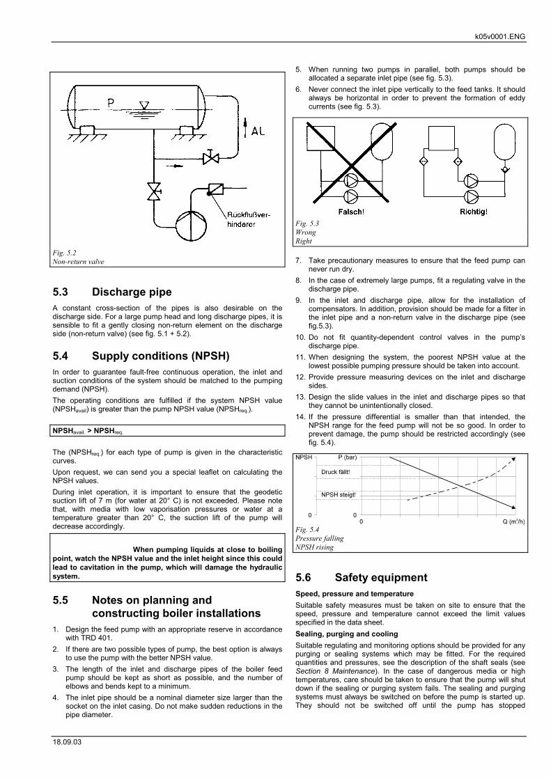
5. When running two pumps in parallel, both pumps should beallocated a separate inlet pipe (see fig. 5.3).
6. Never connect the inlet pipe vertically to the feed tanks. It shouldalways be horizontal in order to prevent the formation of eddycurrents (see fig. 5.3).
7. Take precautionary measures to ensure that the feed pump cannever run dry.
8. In the case of extremely large pumps, fit a regulating valve in thedischarge pipe.
9. In the inlet and discharge pipe, allow for the installation ofcompensators. In addition, provision should be made for a filter inthe inlet pipe and a non-return valve in the discharge pipe (seefig.5.3).
10. Do not fit quantity-dependent control valves in the pump’sdischarge pipe.
11. When designing the system, the poorest NPSH value at thelowest possible pumping pressure should be taken into account.
12. Provide pressure measuring devices on the inlet and dischargesides.
13. Design the slide values in the inlet and discharge pipes so thatthey cannot be unintentionally closed.
14. If the pressure differential is smaller than that intended, theNPSH range for the feed pump will not be so good. In order toprevent damage, the pump should be restricted accordingly (seefig. 5.4).
5.6 Safety equipmentSpeed, pressure and temperatureSuitable safety measures must be taken on site to ensure that thespeed, pressure and temperature cannot exceed the limit valuesspecified in the data sheet.Sealing, purging and coolingSuitable regulating and monitoring options should be provided for anypurging or sealing systems which may be fitted. For the requiredquantities and pressures, see the description of the shaft seals (seeSection 8 Maintenance). In the case of dangerous media or hightemperatures, care should be taken to ensure that the pump will shutdown if the sealing or purging system fails. The sealing and purgingsystems must always be switched on before the pump is started up.They should not be switched off until the pump has stopped
Fig. 5.2Non-return valve
Fig. 5.3WrongRight
Fig. 5.4Pressure fallingNPSH rising
k05v0001.ENG
18.09.03
completely, if this is permitted by the type of operation (see Section 7Start-up and shut-down).Minimum quantities, working rangeThe working range specified in the characteristic curve sheets shouldbe used and the pump should not exceed or fall below this rangeduring operation. The left-hand limit on the characteristic curverepresents the minimum quantity for the pump.Suitable measures, such as freewheel non-return valves or a by-passline, should be provided on site in order to guarantee the minimumquantity for the pump under all operating conditions. Ensure that thetransfer capacity is not exceeded.If required, we will be pleased to help you with the design of thefreewheel non-return valves or by-pass line.The inlet and discharge sides of the pump should each be equippedwith a mano/vacuummeter or manometer. In order to be able tomaintain the pump head precisely (see rating plate), a regulatingvalve should be provided on the discharge side. For larger pumpheads (> 20 m), long pipes, parallel operation and system counter-pressure, a non-return valve (R) should be installed on the dischargeside in order to prevent back-flow through the pump when the unit isswitched off (see fig. 5.1 + 5.2).
5.7 Electrical connections
The power supply cable for the driving motor shouldbe connected by a qualified electrician in accordance with themotor manufacturer’s circuit diagram. The applicable VDEregulations and the regulations of the local electricity companyshould be observed. All risks of electric shock should beeliminated.
5.8 InspectionOnce installation is complete, all the pipes and sockets should betested to ensure they are airtight. The unit should be tested to ensurethat it is free of blockages (It should be possible to turn the shaftassembly by hand).
The operational safety of the installation (electricalconnections, coupling guards, etc.) should be checked withreference to the applicable accident prevention regulations.
5.9 Hydrostatic pressure testWhen carrying out a hydrostatic pressure test on the piping systems,the pump should be excluded from the test.If the pipes cannot be pressure tested without the pump, care shouldbe taken to ensure that no foreign bodies enter the pump.The maximum pressure that may be applied to the pump during thetest is 1.3 times the design pressure of the pump. The designpressure is given in the data sheet in the appendix.In the case of pumps with a gland, the packing should be replacedafter the pressure test (since it will be compressed too much and willno longer be suitable for use). When emptying the pipe after thepressure test, a preservative agent should be applied to the pump (toavoid rusting and problems during start-up). The pipes must beconnected to the pump so that the reaction forces which occur on thepipes never exceed the maximum admissible forces and torques atthe pipe sockets.Before start-up, the piping system and installed fittings, devices, etcmust be cleaned of impurities such as weld beads, scale, etc.
k06v0001.ENG
Updated: 25.04.05
6. Installing the pump
6.1 Safety measures
Carefully connect the pipes in order to prevent themedium used leaking out during pumping and endangering theoperators.Ensure that the inlet and feed pipes and the discharge pipe areclosed off.
Ensure that all the electrical connections areswitched off in order to prevent potentially fatal electric shocks.
6.2 Assembly toolsNo special tools are required for setting up and installation.
6.3 Initial installation
6.3.1 Ambient conditionsThe ambient temperature may be between -20° C and +40° C. Theair humidity should be as low as possible in order to preventcorrosion.
6.3.2 Sub-floor and foundationThe pump must stand on a flat, vibration-free floor or foundation. Incases of doubt, vibration-damping feet should be used.
6.3.3 Spatial requirementsThe spatial requirements of the pump unit are given in the table ofdimensions. Ensure that there are no obstructions to prevent accessto the shut-off and control valves and to the measuring devices.
Sufficient space should be provided formaintenance and repair work, particularly for replacing the drivemotor or entire pump unit.
6.3.4 Pre-installation checksBefore incorporating the pump into the system, the following pointsshould be checked:� Has the drive motor been switched off?
� Have the inlet, feed and discharge pipes been drained and closedoff?
� Can the pump be easily turned by hand (by turning the impelleron the motor)?
� Have all the internal company regulations been followed?
6.3.5 Installing the pump andincorporating it into the pipingsystem
Align the pump with the pipes. The pipes should be supported sothat, when the pump is connected, no twisting can occur. Whentightening the screws, follow the sequence given below:1. Tighten the flanged connections. Remove the protective caps
from the connectors before connecting the pipe.
2. Tighten the pump feet and motor feet. The feet should only behand tight.
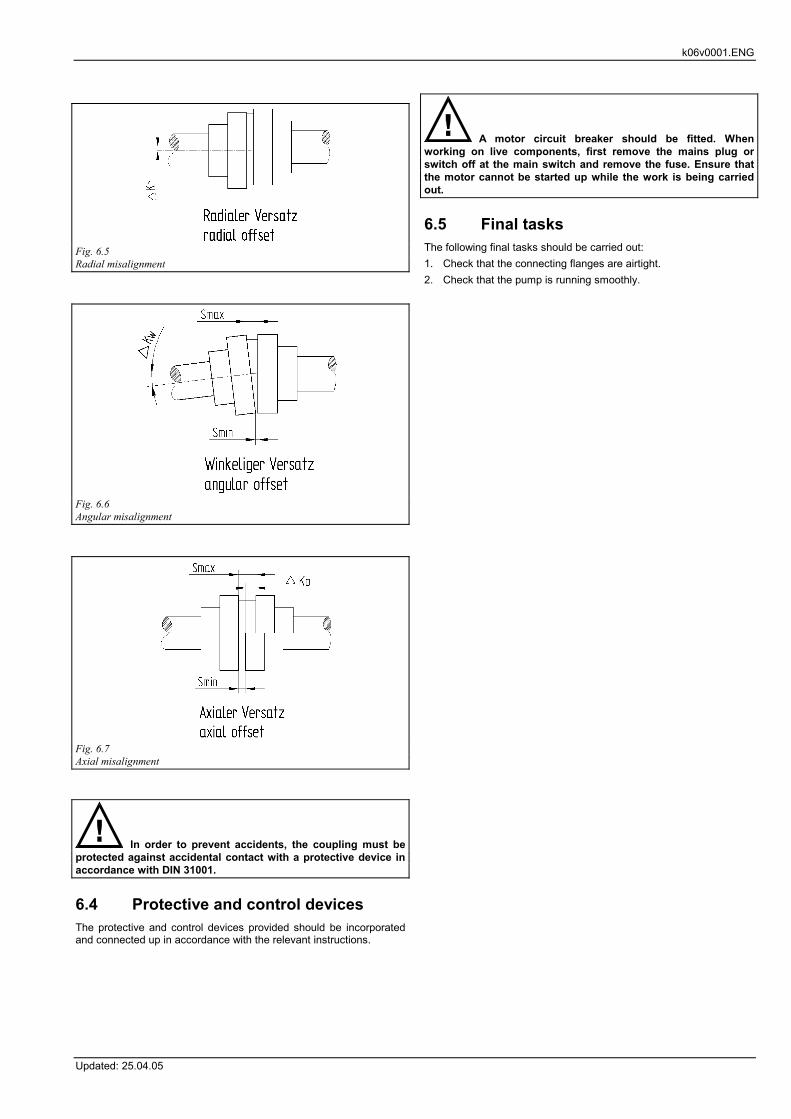
6.3.6 Checking the flexible couplingAfter connecting the pipes, the alignment of the coupling must bechecked, and adjusted if necessary.
Admissible misalignment for flexible couplings (only applies tooriginal couplings supplied by us):
In order to prevent accidents, the coupling must beprotected against accidental contact with a protective device inaccordance with DIN 31001.
6.4 Protective and control devicesThe protective and control devices provided should be incorporatedand connected up in accordance with the relevant instructions.
A motor circuit breaker should be fitted. Whenworking on live components, first remove the mains plug orswitch off at the main switch and remove the fuse. Ensure thatthe motor cannot be started up while the work is being carriedout.
6.5 Final tasksThe following final tasks should be carried out:1. Check that the connecting flanges are airtight.2. Check that the pump is running smoothly.
Fig. 6.5Radial misalignment
Fig. 6.6Angular misalignment
Fig. 6.7Axial misalignment
K07V0003.eng
02.10.95
7. Start-up and Shut-down
7.1 Safety measures
Electrical connections must be made in accordancewith the regulations of the local electricity company and theELexV specifications. The German Chemistry Society’s guidelinefor hazardous locations must also be observed. This work mustonly be carried out by authorised personnel.
Fill the pump in accordance with the instructions, inorder to avoid any risk of damage.When using hot media, fill the pump slowly in order to preventdistortion or thermal shocks.When using explosive, poisonous, hot or caustic media, ensurethat they cannot endanger life or the environment.Adjust the flow at a constant pump speed and only on thedischarge side. The control device on the inlet or supply sidemust always be fully open during operation.
7.2 Preparations for start-up
7.2.1 Filling the pumpCompletely fill the pump with the medium to be pumped. Ventthe pump at the flanges via the connection auxiliaries. This onlyneeds doing once and, if necessary, can be carried out before thepipe is connected. The next time the pump is started up, it will primeitself automatically.Check the pump shaft to ensure that it is running smoothly. Checkthat all the connection auxiliaries are ready for operation. Open allthe shut-off devices in the inlet and discharge pipes. Whenpumping media at temperatures > 100° C, the pump (body of thepump) should be warmed before start-up, ideally by filling it with thehot medium and allowing this to flow through until the body of thepump reaches roughly the same temperature as the medium (at least10 minutes).
Under no circumstances must the pumpbe allowed to run dry, since overheating could damage thepump components.
7.2.2 Driving motor
The electrical connection work must be carried out bya qualified electrician, following the VDE and local regulations,particularly the protective measures. Check the operatingvoltage and speed of the motor. At 50 Hz, the speed should be1450 rpm and at 60 Hz, it should be 1750 rpm. A motor circuit-breaker should be fitted.
7.2.3 BearingsThe bearings are adequately greased at the factory and are ready foroperation.
7.2.4 Checking the direction of rotationThe direction of rotation of the motor must be the same as therotation arrow on the pump. These arrows are marked on the pump.
The motor may be switched on briefly in order to check the directionof rotation. If the direction of rotation is incorrect, the pump may bedamaged.
Never allow the pump to run against theprescribed direction of rotation. Only check the direction ofrotation when the pump is full.
7.3 Start-up
7.3.1 Switching onSwitch on the motor.
Never (even briefly) start or operate thepump when the discharge side is closed. Do not switch thepump on until the shut-off device is open. The slide valves in theinlet pipe must also be open.If a bypass pipe is fitted, it must be closed during inlet operation.During supply operation, it may remain open. After running the unit upto the nominal speed (see rating plate), adjust the pump head byslowly closing the valve on the discharge side.The priming time depends on the length of the inlet pipe and it willtake a few seconds the first time the pump is used. If a foot valve ornon-return valve is used in the inlet pipe, the pump will start to workas soon as it is switched on.
7.3.2 Setting the pumping capacityvalues
Once normal pumping has started, the flow can be adjusted. Theoperational data for the pump is given on the rating plate and in thedata sheet. The pump head required should be monitored on themanometer display and, if it is not correct, it should be adjusted onthe discharge side. Never run the pump with the discharge sideclosed, even during operation.
If there is a possibility that the pressure inthe pump’s cross-section at the discharge side could rise to aninadmissible level due to a malfunction during operation,suitable safety measures (e.g. fitting a safety valve) should beincorporated into the system.
7.3.3 Maintaining a minimum flowIn order to prevent damage to the pump, never run it against a closedshut-off valve in the discharge pipe.Safety measures (e.g. an overflow valve) should be incorporated intothe system to ensure that the working pressure is not exceededduring operation on account of a malfunction.
The minimum flow is shown on thepump’s output curve (smallest proven Q value).
7.3.4 TemperatureSudden changes in temperature (thermal shocks) should be avoided.
7.3.5 Liquids with a high specific gravityIf the specific gravity of the liquid pumped is greater than thatspecified in the order data (i.e. greater than the specific gravity onwhich the design of the pump was based), the performance of thepump will decrease, while the power consumption will increase.Ensure that the motor is not overloaded.
K07V0003.eng
02.10.95
7.3.6 Higher flow rates
If the flow is greater than that specified inthe order and design data, ensure that the available inlet heightis still sufficient (Condition: NPSHavail > NPSHreq); otherwise,cavitation could occur, with damaging consequences.If the pump is used as a boiler feed pump, ensure that the pump isnot used at a lower working pressure than the intended pressure. Ifthe feed boiler is occasionally run at a lower working pressure, thenthe pump must be restricted to the normal working pressure of theboiler by means of a manual shut-off valve on the discharge side anda manometer connected to the discharge socket on the pump casing.
7.3.7 Switching frequencyThe pump must not be switched on and off more than 10 times perhour.
7.4 Shut-down and restart
7.4.1 Switching offThe valves on the discharge and inlet sides must not be closedbefore the pump is stopped. Switch off the motor.Ensure that the pump runs down evenly. If non-return valves havebeen fitted, the shut-off devices may not close.For long stoppages and in the event of excess (feed) pressure on theinlet side, the shut-off valve on the inlet side should be closed. Theauxiliary devices (sealing liquid, etc.) should be switched off.In the case of pumps in which the liquid is under vacuum, it isimportant to check before starting up again whether there is stillenough liquid in the pump. The pump should be topped up ifnecessary.If the pump remains pressurised and hot, even when shut down, allthe available sealing pipes should be opened. The sealing devicesmust remain switched on if there is a risk of taking in air (when thepump is supplied from vacuum installations or if pumps are operatedin parallel with a common intake pipe). If there is a risk of frost,completely empty the pump and pipes.
7.4.2 RestartCheck that the pump shaft has stopped. If the non-return valve in thedischarge pipe is not airtight, backflow of the pumped liquid maycause the pump shaft to rotate backwards. The pump must not beswitched on if the pump shaft is rotating backwards, since this couldresult in damage to the pump.
7.5 Precautions in the event of longstoppages
If pumps are stored for long periods before installation, they shouldbe protected against moisture and dirt (e.g. by wrapping them in oiledpaper or plastic film).If the pumps are stored, the inlet and discharge pipe sockets and allother intake and outlet sockets must immediately be closed off withblanking flanges or plugs.During storage, the pump should be rotated at least once a month(do not switch on since it will be running dry). The position of partssuch as the shaft and ball bearings should be moved each time. Ifnecessary, they can be released by lightly tapping the shaft in theaxial direction. They must be replaced after no more than 4 years,since the grease will be unusable on account of ageing.
K08V0003.ENG
02.10.95
8. Maintenance
8.1 Safety measures
When carrying out maintenance and repair work, theinformation given in Section 2. Safety must be followed. Theservice life will be prolonged if monitoring and maintenancework is carried out regularly on the pump and drive.
8.2 General monitoring� The pump must never be operated dry or with an interruption in
the flow. Check the liquid level in the inlet and feed tanks.
� Never allow the flow to fall below the minimum or exceed themaximum level.
� Monitor the speed and pump head.
� Do not overload the drive motor.
� The pumps and units should always run quietly and withoutvibration. All valves, filters, etc, on the inlet side should be keptcompletely open.
� Check the pressure and temperature monitoring devices and theflow measuring devices.
� Any standby pumps fitted should be brought into service once aweek by switching on and off again.
8.3 Maintenance of components
8.3.1 Bearings and lubricationThe external roller bearings are greased for life. There is no need tolubricate the closed bearings. The temperature of the bearings mustnot exceed 80 °C. If the pump is operating correctly, the bearingsshould be replaced after approximately 10,000 operating hours. Theinternal carbon sliding bearings should also be replaced afterthis period of operation. If excess temperatures are identified, thisindicates damage to the bearings, and the deep-groove ball bearingsshould be replaced as soon as possible (see Section 9. Servicing).
8.3.2 Flexible couplingThe condition of the flexible elements in the coupling should bechecked at regular intervals. Note: Replace any worn flexibleelements. The distance between the two halves of the couplingshould be checked for the first time after approximately 1,000operating hours (see Section 6.3.6 Checking the flexible coupling).The rubber coupling blocks in the jaw clutch couplings should bechecked. If there is significant wear, it must be assumed that themotor is not flush with the pump or that the distance between the twohalves of the coupling has changed. This will result in damage to thepump’s bearings.
8.3.3 DriveSee the operating instructions provided by the drive manufacturer.
8.3.4 Mechanical sealsMechanical seals require no maintenance, but will only remain leak-free if looked after. During operation, ensure that the mechanicalseals never run dry and the conditions of use are within the limits foruse of the selected mechanical seal. A leak of approximately 2.5 cm³per hour is admissible.
If leaks occur at the mechanical seal, the seal cannot be tightened.We recommend dismantling and checking the mechanical seal, theshaft and the adjacent sealing elements. Since the service life ofmechanical seals cannot normally be estimated, we recommendkeeping a stock of spare seals.
K09v0014.eng
02.10.95
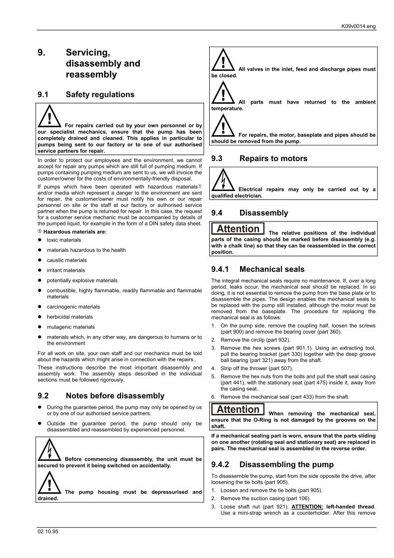
9. Servicing,disassembly andreassembly
9.1 Safety regulations
For repairs carried out by your own personnel or byour specialist mechanics, ensure that the pump has beencompletely drained and cleaned. This applies in particular topumps being sent to our factory or to one of our authorisedservice partners for repair.In order to protect our employees and the environment, we cannotaccept for repair any pumps which are still full of pumping medium. Ifpumps containing pumping medium are sent to us, we will invoice thecustomer/owner for the costs of environmentally-friendly disposal.If pumps which have been operated with hazardous materials�and/or media which represent a danger to the environment are sentfor repair, the customer/owner must notify his own or our repairpersonnel on site or the staff at our factory or authorised servicepartner when the pump is returned for repair. In this case, the requestfor a customer service mechanic must be accompanied by details ofthe pumped liquid, for example in the form of a DIN safety data sheet.� Hazardous materials are:� toxic materials
� materials hazardous to the health
� caustic materials
� irritant materials
� potentially explosive materials
� combustible, highly flammable, readily flammable and flammablematerials
� carcinogenic materials
� herbicidal materials
� mutagenic materials
� materials which, in any other way, are dangerous to humans or tothe environment
For all work on site, your own staff and our mechanics must be toldabout the hazards which might arise in connection with the repairs..These instructions describe the most important disassembly andassembly work. The assembly steps described in the individualsections must be followed rigorously.
9.2 Notes before disassembly� During the guarantee period, the pump may only be opened by us
or by one of our authorised service partners.
� Outside the guarantee period, the pump should only bedisassembled and reassembled by experienced personnel.
Before commencing disassembly, the unit must besecured to prevent it being switched on accidentally.
The pump housing must be depressurised anddrained.
All valves in the inlet, feed and discharge pipes mustbe closed.
All parts must have returned to the ambienttemperature.
For repairs, the motor, baseplate and pipes should beshould be removed from the pump.
9.3 Repairs to motors
Electrical repairs may only be carried out by aqualified electrician.
9.4 Disassembly
The relative positions of the individualparts of the casing should be marked before disassembly (e.g.with a chalk line) so that they can be reassembled in the correctposition.
9.4.1 Mechanical sealsThe integral mechanical seals require no maintenance. If, over a longperiod, leaks occur, the mechanical seal should be replaced. In sodoing, it is not essential to remove the pump from the base plate or todisassemble the pipes. The design enables the mechanical seals tobe replaced with the pump still installed, although the motor must beremoved from the baseplate. The procedure for replacing themechanical seal is as follows:1. On the pump side, remove the coupling half, loosen the screws
(part 900) and remove the bearing cover (part 360).2. Remove the circlip (part 932).3. Remove the hex screws (part 901.1). Using an extracting tool,
pull the bearing bracket (part 330) together with the deep grooveball bearing (part 321) away from the shaft.
4. Strip off the thrower (part 507).5. Remove the hex nuts from the bolts and pull the shaft seal casing
(part 441), with the stationary seat (part 475) inside it, away fromthe casing seat.
6. Remove the mechanical seal (part 433) from the shaft.
When removing the mechanical seal,ensure that the O-Ring is not damaged by the grooves on theshaft.If a mechanical sealing part is worn, ensure that the parts slidingon one another (rotating seal and stationary seat) are replaced inpairs. The mechanical seal is assembled in the reverse order.
9.4.2 Disassembling the pumpTo disassemble the pump, start from the side opposite the drive, afterloosening the tie bolts (part 905).1. Loosen and remove the tie bolts (part 905).2. Remove the suction casing (part 106).3. Loose shaft nut (part 921): ATTENTION: left-handed thread.
Use a mini-strap wrench as a counterholder. After this remove
K09v0014.eng
02.10.95
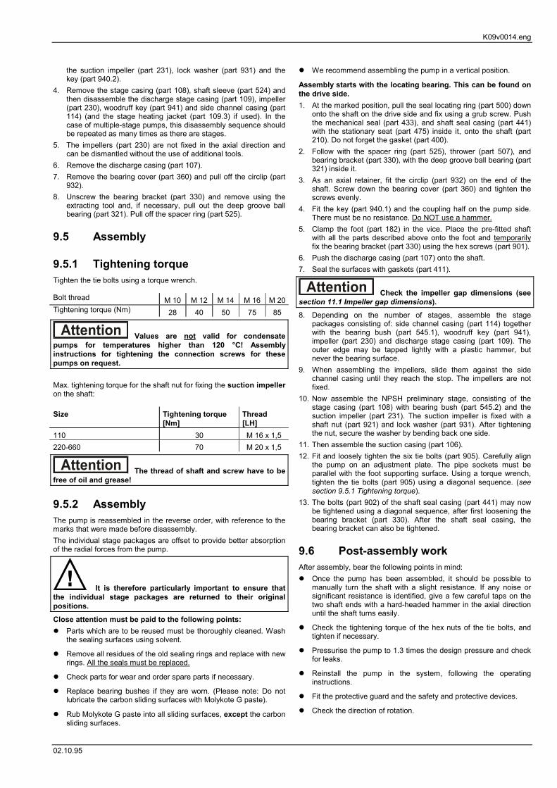
the suction impeller (part 231), lock washer (part 931) and thekey (part 940.2).
4. Remove the stage casing (part 108), shaft sleeve (part 524) andthen disassemble the discharge stage casing (part 109), impeller(part 230), woodruff key (part 941) and side channel casing (part114) (and the stage heating jacket (part 109.3) if used). In thecase of multiple-stage pumps, this disassembly sequence shouldbe repeated as many times as there are stages.
5. The impellers (part 230) are not fixed in the axial direction andcan be dismantled without the use of additional tools.
6. Remove the discharge casing (part 107).7. Remove the bearing cover (part 360) and pull off the circlip (part
932).8. Unscrew the bearing bracket (part 330) and remove using the
extracting tool and, if necessary, pull out the deep groove ballbearing (part 321). Pull off the spacer ring (part 525).
9.5 Assembly
9.5.1 Tightening torqueTighten the tie bolts using a torque wrench.
Bolt thread M 10 M 12 M 14 M 16 M 20Tightening torque (Nm) 28 40 50 75 85
Values are not valid for condensatepumps for temperatures higher than 120 °C! Assemblyinstructions for tightening the connection screws for thesepumps on request.
Max. tightening torque for the shaft nut for fixing the suction impelleron the shaft:
Size Tightening torque[Nm]
Thread[LH]
110 30 M 16 x 1,5220-660 70 M 20 x 1,5
The thread of shaft and screw have to befree of oil and grease!
9.5.2 AssemblyThe pump is reassembled in the reverse order, with reference to themarks that were made before disassembly.The individual stage packages are offset to provide better absorptionof the radial forces from the pump.
It is therefore particularly important to ensure thatthe individual stage packages are returned to their originalpositions.Close attention must be paid to the following points:� Parts which are to be reused must be thoroughly cleaned. Wash
the sealing surfaces using solvent.
� Remove all residues of the old sealing rings and replace with newrings. All the seals must be replaced.
� Check parts for wear and order spare parts if necessary.
� Replace bearing bushes if they are worn. (Please note: Do notlubricate the carbon sliding surfaces with Molykote G paste).
� Rub Molykote G paste into all sliding surfaces, except the carbonsliding surfaces.
� We recommend assembling the pump in a vertical position.
Assembly starts with the locating bearing. This can be found onthe drive side.1. At the marked position, pull the seal locating ring (part 500) down
onto the shaft on the drive side and fix using a grub screw. Pushthe mechanical seal (part 433), and shaft seal casing (part 441)with the stationary seat (part 475) inside it, onto the shaft (part210). Do not forget the gasket (part 400).
2. Follow with the spacer ring (part 525), thrower (part 507), andbearing bracket (part 330), with the deep groove ball bearing (part321) inside it.
3. As an axial retainer, fit the circlip (part 932) on the end of theshaft. Screw down the bearing cover (part 360) and tighten thescrews evenly.
4. Fit the key (part 940.1) and the coupling half on the pump side.There must be no resistance. Do NOT use a hammer.
5. Clamp the foot (part 182) in the vice. Place the pre-fitted shaftwith all the parts described above onto the foot and temporarilyfix the bearing bracket (part 330) using the hex screws (part 901).
6. Push the discharge casing (part 107) onto the shaft.7. Seal the surfaces with gaskets (part 411).
Check the impeller gap dimensions (seesection 11.1 Impeller gap dimensions).8. Depending on the number of stages, assemble the stage
packages consisting of: side channel casing (part 114) togetherwith the bearing bush (part 545.1), woodruff key (part 941),impeller (part 230) and discharge stage casing (part 109). Theouter edge may be tapped lightly with a plastic hammer, butnever the bearing surface.
9. When assembling the impellers, slide them against the sidechannel casing until they reach the stop. The impellers are notfixed.
10. Now assemble the NPSH preliminary stage, consisting of thestage casing (part 108) with bearing bush (part 545.2) and thesuction impeller (part 231). The suction impeller is fixed with ashaft nut (part 921) and lock washer (part 931). After tighteningthe nut, secure the washer by bending back one side.
11. Then assemble the suction casing (part 106).12. Fit and loosely tighten the six tie bolts (part 905). Carefully align
the pump on an adjustment plate. The pipe sockets must beparallel with the foot supporting surface. Using a torque wrench,tighten the tie bolts (part 905) using a diagonal sequence. (seesection 9.5.1 Tightening torque).
13. The bolts (part 902) of the shaft seal casing (part 441) may nowbe tightened using a diagonal sequence, after first loosening thebearing bracket (part 330). After the shaft seal casing, thebearing bracket can also be tightened.
9.6 Post-assembly workAfter assembly, bear the following points in mind:� Once the pump has been assembled, it should be possible to
manually turn the shaft with a slight resistance. If any noise orsignificant resistance is identified, give a few careful taps on thetwo shaft ends with a hard-headed hammer in the axial directionuntil the shaft turns easily.
� Check the tightening torque of the hex nuts of the tie bolts, andtighten if necessary.
� Pressurise the pump to 1.3 times the design pressure and checkfor leaks.
� Reinstall the pump in the system, following the operatinginstructions.
� Fit the protective guard and the safety and protective devices.
� Check the direction of rotation.
K09v0014.eng
02.10.95
� Before starting up again, note the points listed in Section 7 Start-up.
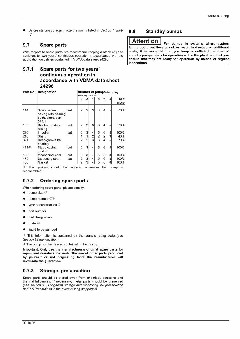
9.7 Spare partsWith respect to spare parts, we recommend keeping a stock of partssufficient for two years’ continuous operation in accordance with theapplication guidelines contained in VDMA data sheet 24296.
9.7.1 Spare parts for two years’continuous operation inaccordance with VDMA data sheet24296
Part No. Designation Number of pumps (includingstandby pumps)
2 3 4 5 6 8 10 +more
114 Side channelcasing with bearingbush, short, part545.1
� This information is contained on the pump’s rating plate (seeSection 12 Identification).� The pump number is also contained in the casing.Important: Only use the manufacturer’s original spare parts forrepair and maintenance work. The use of other parts producedby yourself or not originating from the manufacturer willinvalidate the guarantee.
9.7.3 Storage, preservationSpare parts should be stored away from chemical, corrosive andthermal influences. If necessary, metal parts should be preserved(see section 3.7 Long-term storage and monitoring the preservationand 7.5 Precautions in the event of long stoppages).
9.8 Standby pumps
For pumps in systems where systemfailure could put lives at risk or result in damage or additionalcosts, it is essential that you keep a sufficient number ofstandby pumps ready for operation within the plant, and that youensure that they are ready for operation by means of regularinspections.
K10V0003.ENG
02.10.95
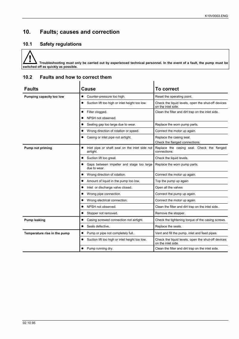
10. Faults; causes and correction
10.1 Safety regulations
Troubleshooting must only be carried out by experienced technical personnel. In the event of a fault, the pump must beswitched off as quickly as possible.
10.2 Faults and how to correct them
Faults Cause To correctPumping capacity too low � Counter-pressure too high. Reset the operating point.
� Suction lift too high or inlet height too low. Check the liquid levels, open the shut-off deviceson the inlet side.
� Filter clogged.
� NPSH not observed.
Clean the filter and dirt trap on the inlet side.
� Sealing gap too large due to wear. Replace the worn pump parts.
� Wrong direction of rotation or speed. Connect the motor up again.
� Casing or inlet pipe not airtight. Replace the casing seal.Check the flanged connections.
Pump not priming � Inlet pipe or shaft seal on the inlet side notairtight.
Replace the casing seal. Check the flangedconnections.
� Suction lift too great. Check the liquid levels.
� Gaps between impeller and stage too largedue to wear.
Replace the worn pump parts.
� Wrong direction of rotation. Connect the motor up again.
� Amount of liquid in the pump too low. Top the pump up again
� Inlet or discharge valve closed. Open all the valves
� Wrong pipe connection. Connect the pump up again.
� Wrong electrical connection. Connect the motor up again.
� NPSH not observed. Clean the filter and dirt trap on the inlet side.
� Stopper not removed. Remove the stopper.
Pump leaking � Casing screwed connection not airtight. Check the tightening torque of the casing screws.
� Seals defective. Replace the seals.
Temperature rise in the pump � Pump or pipe not completely full. Vent and fill the pump, inlet and feed pipes.
� Suction lift too high or inlet height too low. Check the liquid levels, open the shut-off deviceson the inlet side.
� Pump running dry. Clean the filter and dirt trap on the inlet side.
K10V0003.ENG
02.10.95
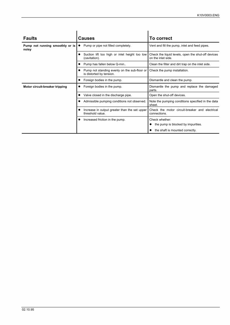
Faults Causes To correctPump not running smoothly or isnoisy
� Pump or pipe not filled completely. Vent and fill the pump, inlet and feed pipes.
� Suction lift too high or inlet height too low(cavitation).
Check the liquid levels, open the shut-off deviceson the inlet side.
� Pump has fallen below Q-min.. Clean the filter and dirt trap on the inlet side.
� Pump not standing evenly on the sub-floor oris distorted by tension.
Check the pump installation.
� Foreign bodies in the pump. Dismantle and clean the pump.
Motor circuit-breaker tripping � Foreign bodies in the pump. Dismantle the pump and replace the damagedparts.
� Valve closed in the discharge pipe. Open the shut-off devices.
� Admissible pumping conditions not observed. Note the pumping conditions specified in the datasheet.
� Increase in output greater than the set upperthreshold value.
Check the motor circuit-breaker and electricalconnections.
� Increased friction in the pump. Check whether:� the pump is blocked by impurities.
� the shaft is mounted correctly.
k11v0003.ENG
02.10.95
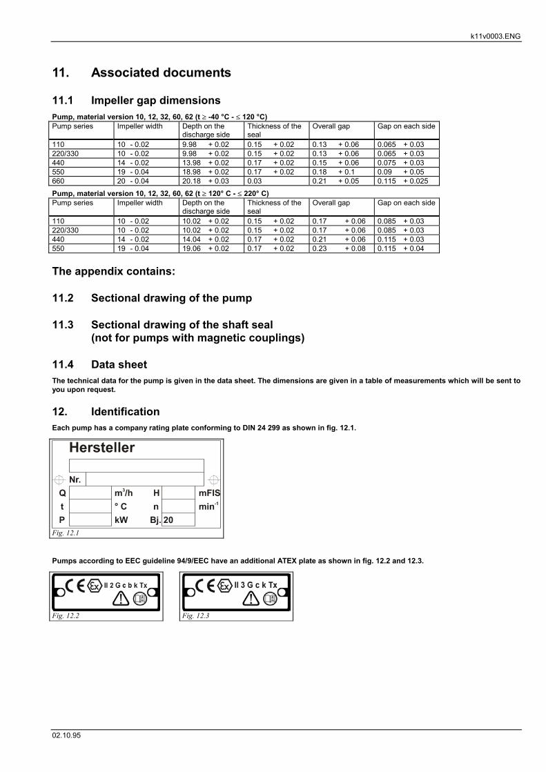
11. Associated documents
11.1 Impeller gap dimensionsPump, material version 10, 12, 32, 60, 62 (t � -40 °C - � 120 °C)Pump series Impeller width Depth on the
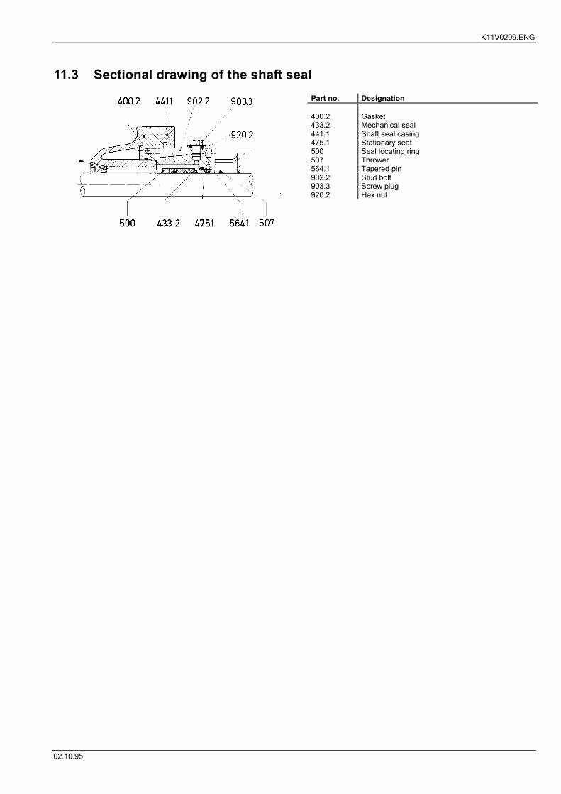
11.3 Sectional drawing of the shaft seal(not for pumps with magnetic couplings)
11.4 Data sheetThe technical data for the pump is given in the data sheet. The dimensions are given in a table of measurements which will be sent toyou upon request.
12. IdentificationEach pump has a company rating plate conforming to DIN 24 299 as shown in fig. 12.1.
Pumps according to EEC guideline 94/9/EEC have an additional ATEX plate as shown in fig. 12.2 and 12.3.
Fig. 12.1
Fig. 12.2 Fig. 12.3
K11v0110.eng
02.10.95
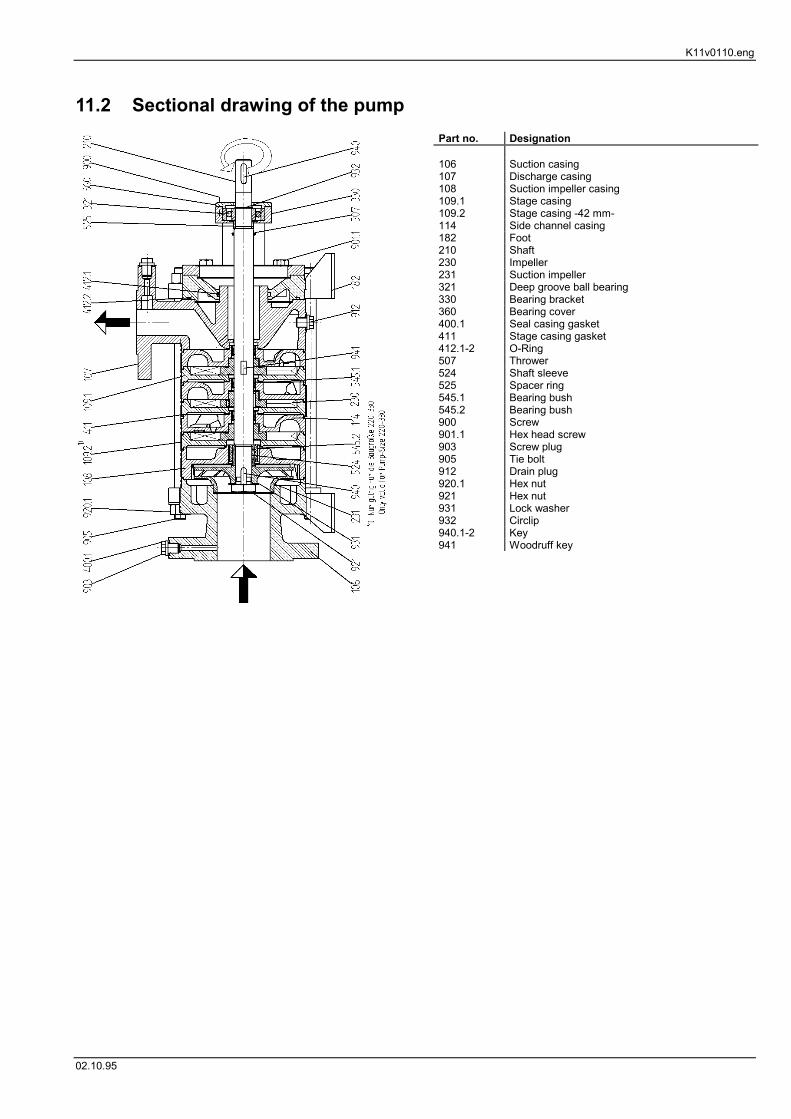
11.2 Sectional drawing of the pumpPart no. Designation
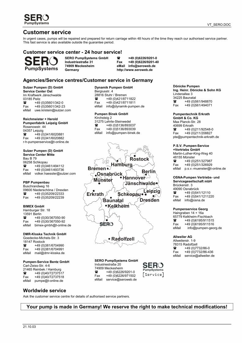
Customer serviceIn urgent cases, pumps will be repaired and prepared for return carriage within 48 hours of the time they reach our authorised service partner.This fast service is also available outside the guarantee period.
Customer service center - 24 hour service!SERO PumpSystems GmbHIndustriestraße 3174909 MeckesheimGermany